Supplies of the Ship Modeler's Handbook are running out. Get your copy NOW before they are gone! Click on photo to order.
×


Stuntflyer
-
Posts
1,196 -
Joined
-
Last visited
Content Type
Profiles
Forums
Gallery
Events
Everything posted by Stuntflyer
-
 Scott, The knee looks nice! It looks like your trying to cut right on the bulkhead template lines. You could cut the bulkheads a 1/64" or so outside those lines to be safe. A lot easier to remove material than to add it. Mike
 -
Last week I started the process of tick marking and lining off the hull. I used Chuck's templates which proved to be very helpful, though not perfect. My hull is not exactly the same as his, so after lining off the hull some adjustments were made before starting the planking of the first belt. While adding the last plank of the third strake I noticed that there were still a few tick marks that were off a bit. For some peace of mind, I lined off that area of the hull again and adjusted the tick marks accordingly. Though not exactly a fun process, I can definitely see the benefit in lining off. Not doing it could lead to some regrets later on. Mike

- 607 replies
-
- 23
-

-
- winchelsea
- Syren Ship Model Company
- (and 1 more)
-
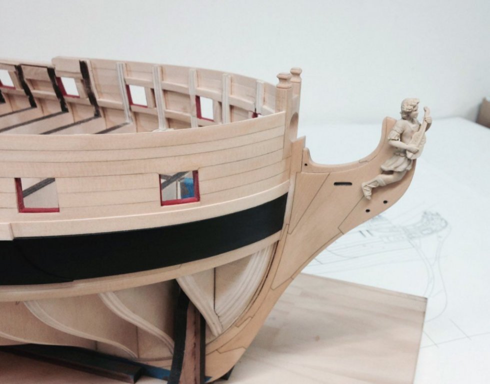
I was driving home from Chuck's on Saturday when I noticed that sunlight coming through the car window exposed a few misses in my initial sanding of the upper planks. So, I was anxious to correct this asap. Once that was taken care of I added the forecastle fairing cap, port side. This was made from boxwood sheet as described in Chuck's Cheerful instructions. Also, I was able to check out Chuck's fancy molding and volutes over the weekend and they are really nice. Turns out that they will completely cover any gaps around the area of the hance fairing caps. Just one more thing I was worried about for nothing. Mike
- 607 replies
-
- 21
-
-
- winchelsea
- Syren Ship Model Company
- (and 1 more)
-
I color corrected the bottom one, hope that's okay?

- 1,784 replies
-
- 4
-
-
- winchelsea
- Syren Ship Model Company
- (and 1 more)
-
I think that the first one which shows both ships is the best, but still not that accurate.
- 1,784 replies
-
- 1
-
-
- winchelsea
- Syren Ship Model Company
- (and 1 more)
-
IPhone photos are a lot more color accurate than the other camera, Chuck Mike
- 1,784 replies
-
- 1
-
-
- winchelsea
- Syren Ship Model Company
- (and 1 more)
-
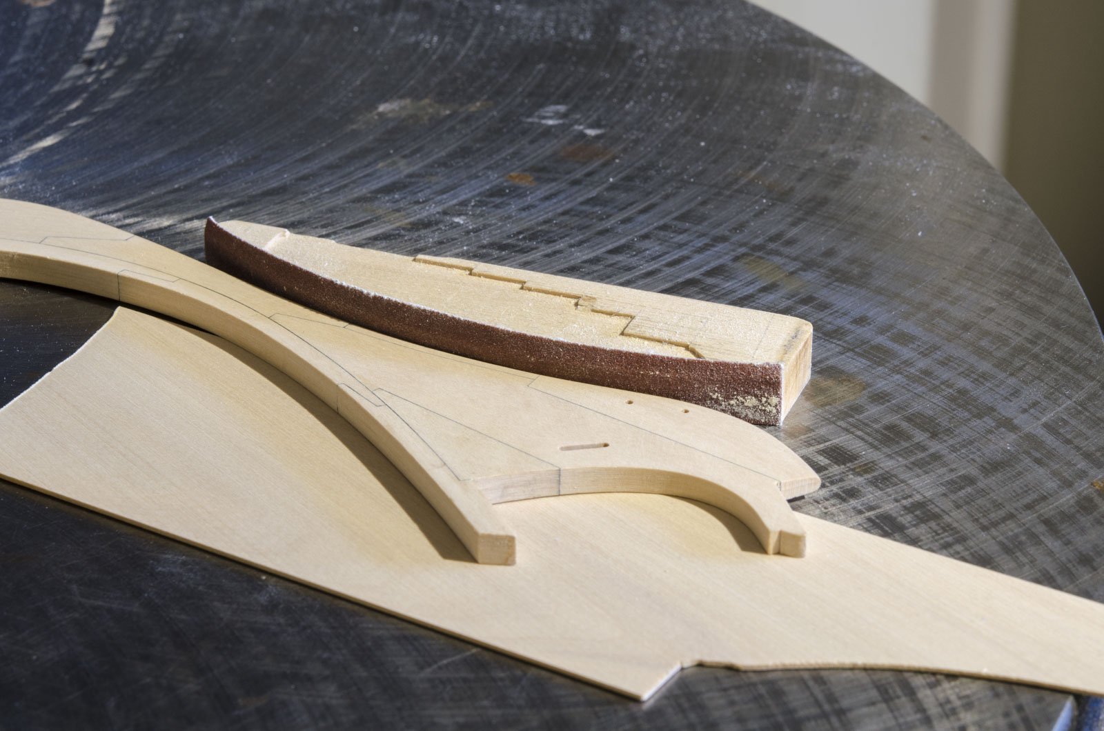
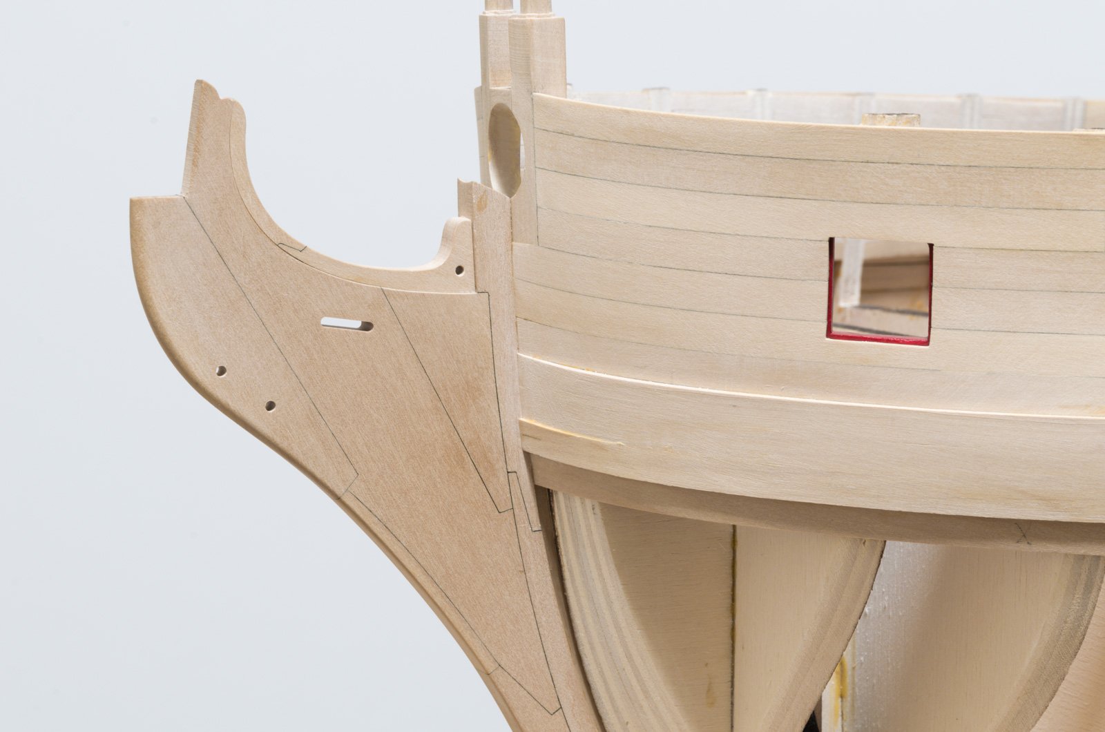
Thanks, Lou, The knee sections are large enough to handle at this scale. Paper templates taken from the plan were glued to the wood parts with school glue. The scroll saw was used to cut the initial shapes by cutting close to the line. Drum sanding along with the disc sander and hand sanding was used to get the parts to the proper shape. Paper templates were then removed. Working on two adjoining parts at a time, the parts were checked for fit by holding them together against a glass window or light box. Light coming thru will show any gaps in the fit. I spent a lot of time finessing these parts for a near perfect fit. Once completed the two parts are glued together and the next part is made to fit to the completed assembly. The three sections along the stem were completed before adding them to the knee. The gammon slot was done on the mill. Something I picked up from druxey describes how he uses various shaped sanding blocks, cut at a 90° angle to get the needed shape. In order to sand the whole edge, simply raise the part of the flat surface with scrap sheet of wood and then run the block over a flat surface and against the part. I know it's a rather short explanation, but I'm hoping that it helps. Mike

- 607 replies
-
- 13
-
-
- winchelsea
- Syren Ship Model Company
- (and 1 more)
-
Hi Mark, What I find most interesting is your making the port stop blocks in such a way that two blocks can be used to handle any port shape and size by using wedges for spreading them. The suggestion that druxey had of using a sanding sealer should definitely help if cleanup is needed. Mike
-
Thank you all for the nice comments and for all the "Likes". Chuck, I will have the poly on the upper planking sometime this week. I've been putting it off for too long. Mike
- 607 replies
-
- 7
-
-
- winchelsea
- Syren Ship Model Company
- (and 1 more)
-
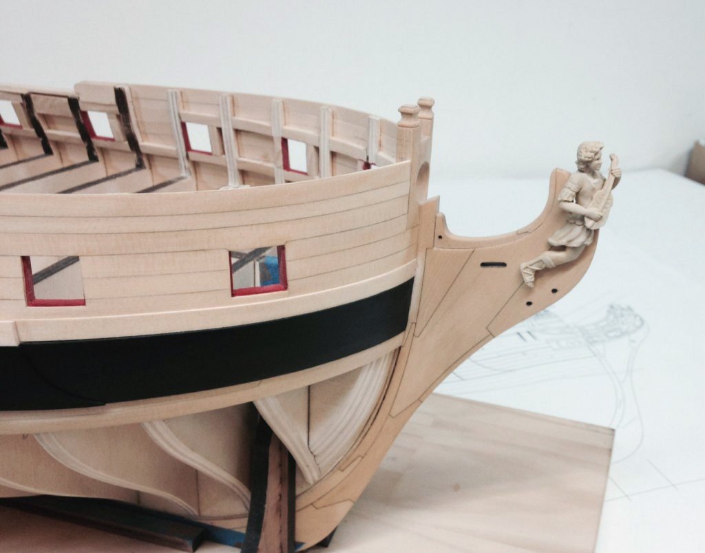
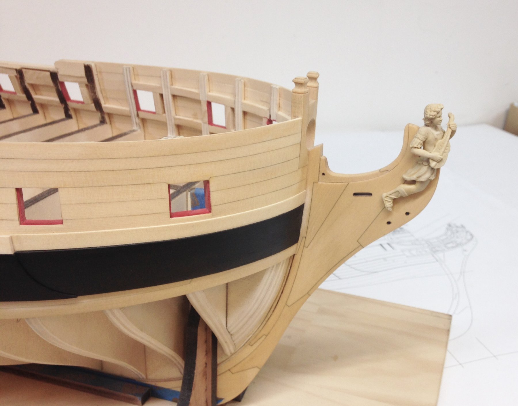
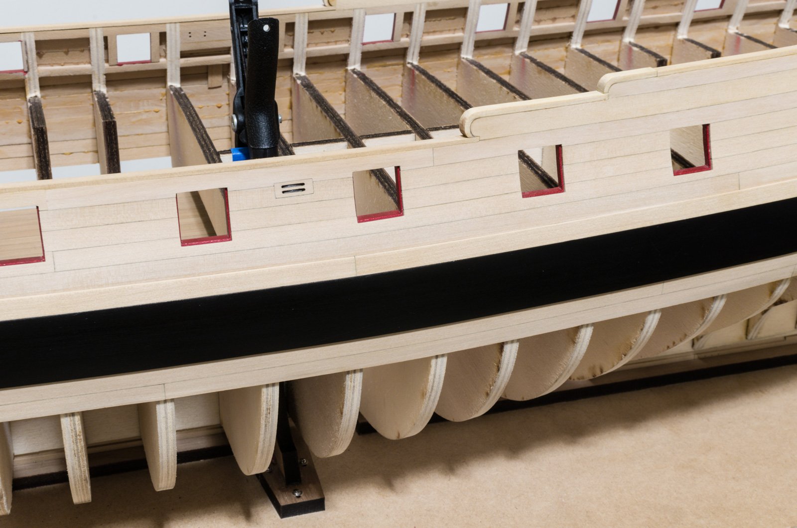
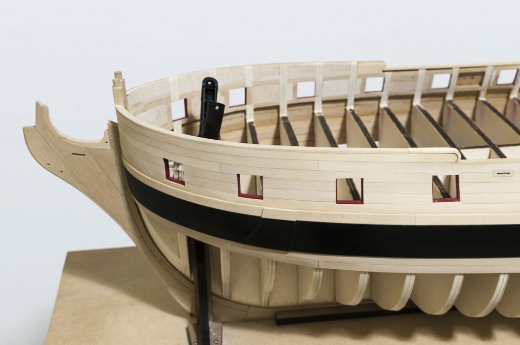
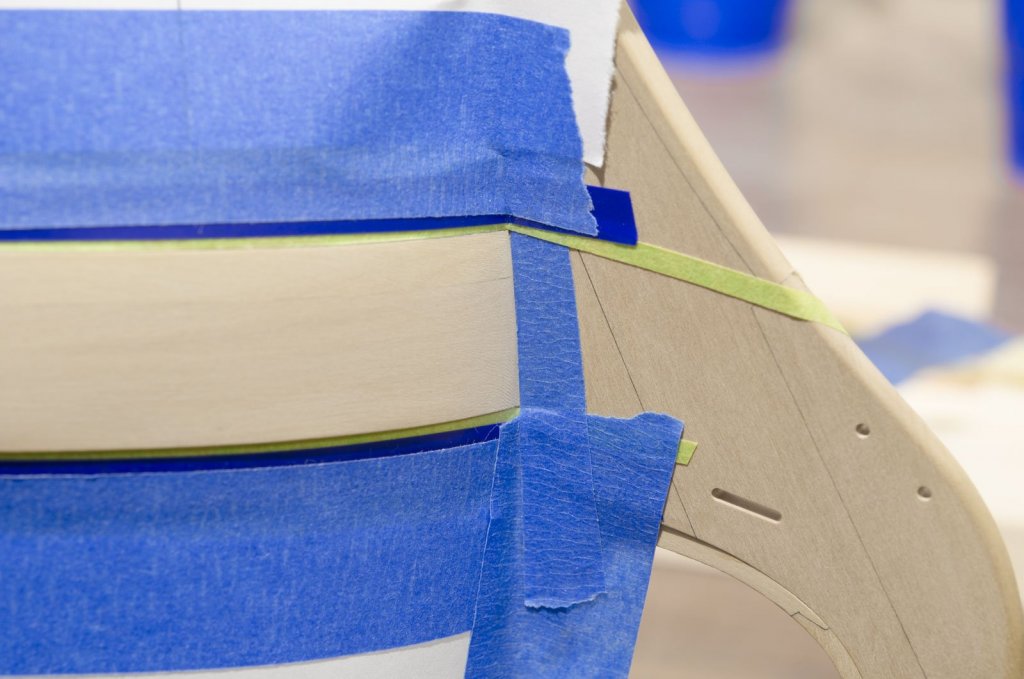
I managed to complete a few things this week. . In preparation for spray painting the wales on the port side I added the section of anchor lining that will be painted black. It was tapered down to 1/64" at the bottom. The hull was then taped off along the wales. After painting was completed, I added the black strake. This was done in four sections. I also added the 3/16" wide fairing caps over the top of the sheer. The ones over the hance pieces were laser cut and the 3/16" x 1/16" strips were cut on the table saw. From what I understand, the final shaping of the hance fairing caps will be done after the fancy molding and volutes are in place. To finish off the anchor lining, I added the clear piece that sits above. Mike

- 607 replies
-
- 27
-
-
- winchelsea
- Syren Ship Model Company
- (and 1 more)
-
Great job as usual, Thomas! Mike
-
I'm using Winsor & Newton acrylic paint. Grumbacher is also a good choice. I prefer to airbrush over hand painting, but that depends on how difficult it is to mask off the area being painted. Mike
-
Hi Mark, It doesn't seem possible to prevent the stain from wicking into the plank ends. Then there is the issue of matching the paint to the stained areas. Have you considered doing everything with just paint? Mike
-
Mark, I did not measure anything on the frames beforehand, though I did consider using a stop block. Since the gunports are not all the same shape, making a stop block for every port was more than I wanted to do. The reveals were all done by eye with the aid of the OptiVISOR. Also, I didn't sand the plank ends by hand. I used the disc sander either powered or by hand rotation depending on how much I needed to finesse the fit. For the joints between the planks, I like to use a number 2b pencil on one plank edge only and not on both edges being joined. Mike
- 607 replies
-
- 12
-
-
- winchelsea
- Syren Ship Model Company
- (and 1 more)
-
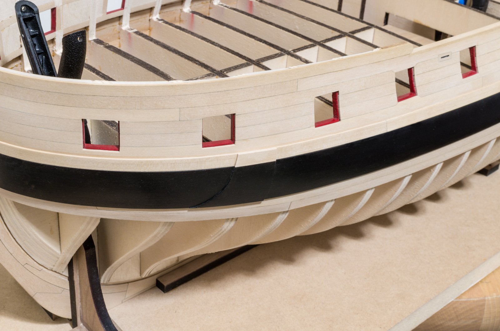
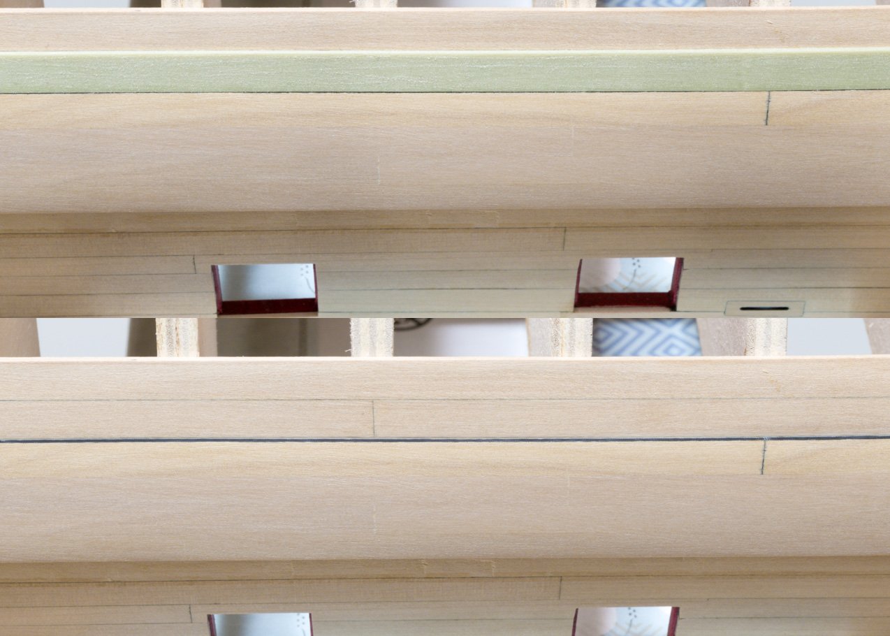
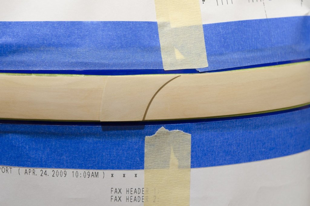
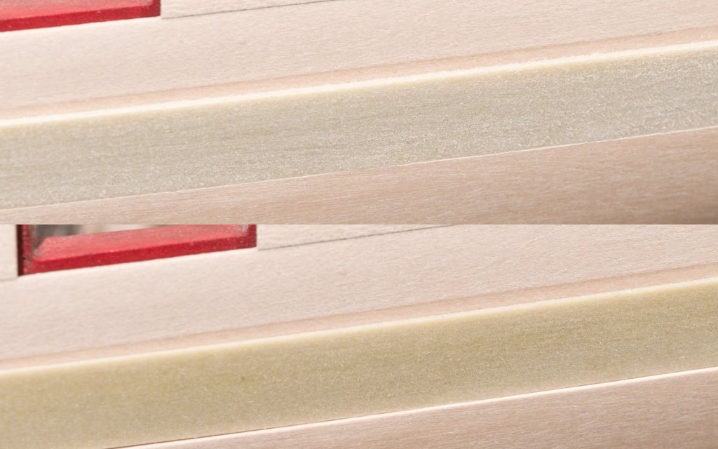
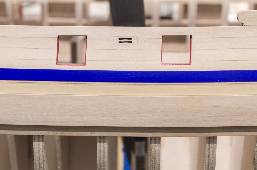
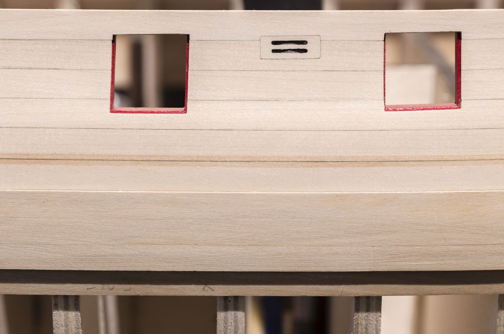
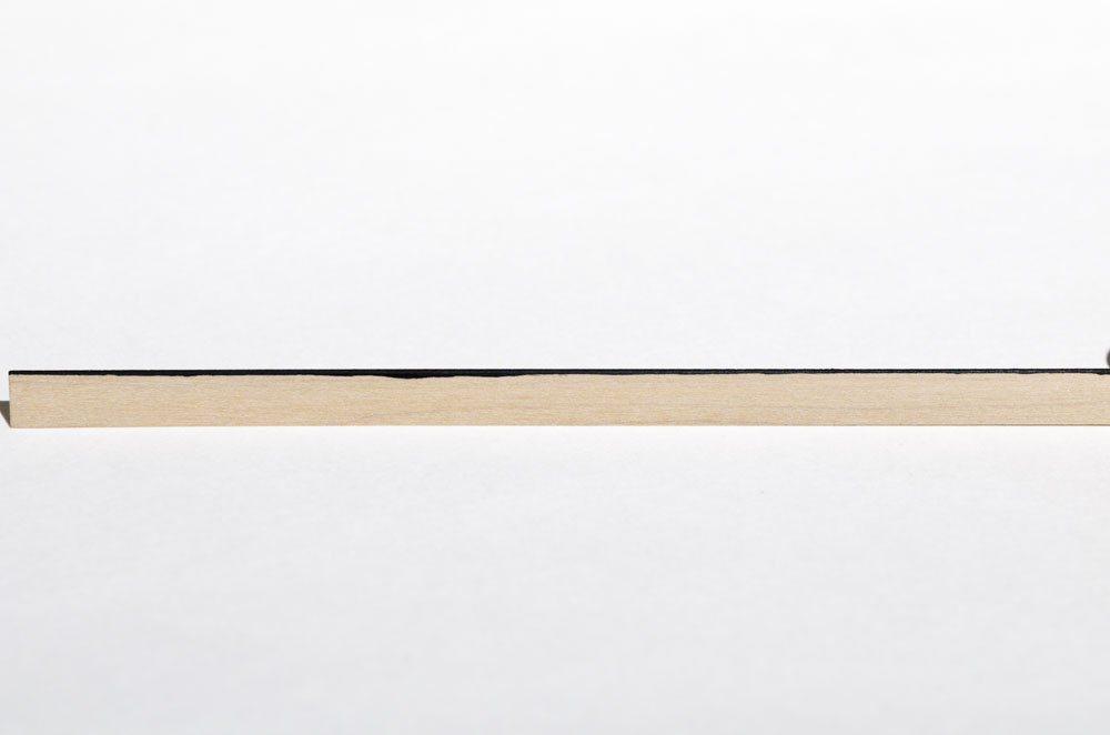
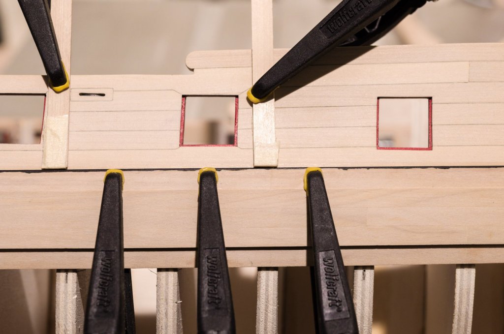
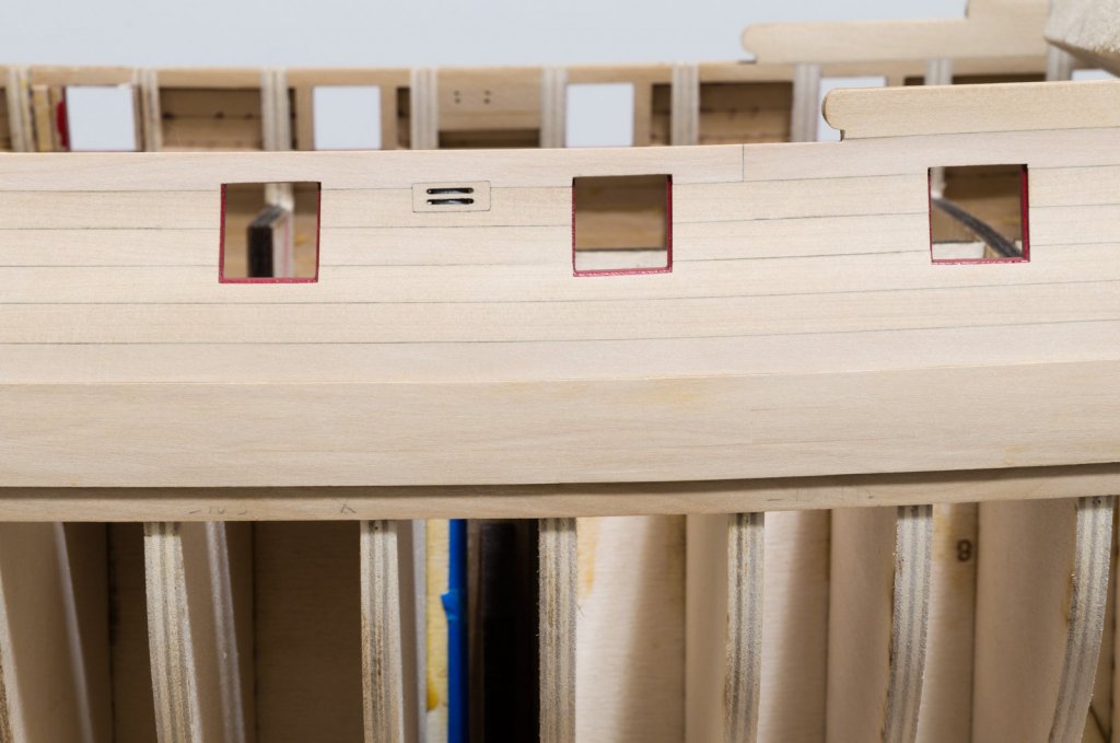
After a lengthy discussion and given the choice to remain with a painted black strake or switch to a natural one, I decided to go with a natural one. I removed the black strakes shown in post #129. They popped off rather easily using a small chisel as a wedge. The new black strakes will be added after the wales are painted. Something I didn't do the first time around was to make sure that the top edge of the wales were of even thickness throughout. To do this, I added nine layers of .005" striping tape to achieve the wale thickness of .045". I was not surprised to see that the thickness does vary a bit which I attribute to the gluing process and not to variation in wood thickness. The upper edge of the wales were sanded down close to the tape surface. Once completed the first three three layers of tape were removed. The remaining 1/32" thickness of tape is equal to the black strake thickness and the 1/64" exposed edge can now be tapered and softened. The photo below shows the before and after. The drop plank was made from 3/64" boxwood sheet and installed before the last 2nd layer wale strake was added. The two rows of planks that follow the drop plank were also completed. Some creative clamping was used in order to hold things down The last wale strake was painted black on one edge and glued into place. Once done, the striping tape used in the previous step was placed below it. The bottom edge of the wale is tapered down to approx 1/32". The photo below shows the before and after. Now onto the other side before painting the wales. Mike


- 607 replies
-
- 30
-
-
- winchelsea
- Syren Ship Model Company
- (and 1 more)
-
I forgot about that, Chuck. Thanks for the reminder. Mike
- 607 replies
-
- 4
-
-
- winchelsea
- Syren Ship Model Company
- (and 1 more)
-
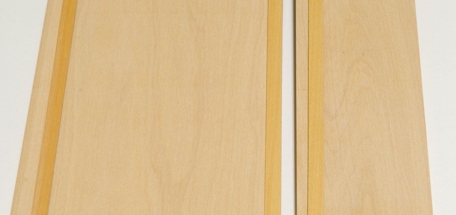
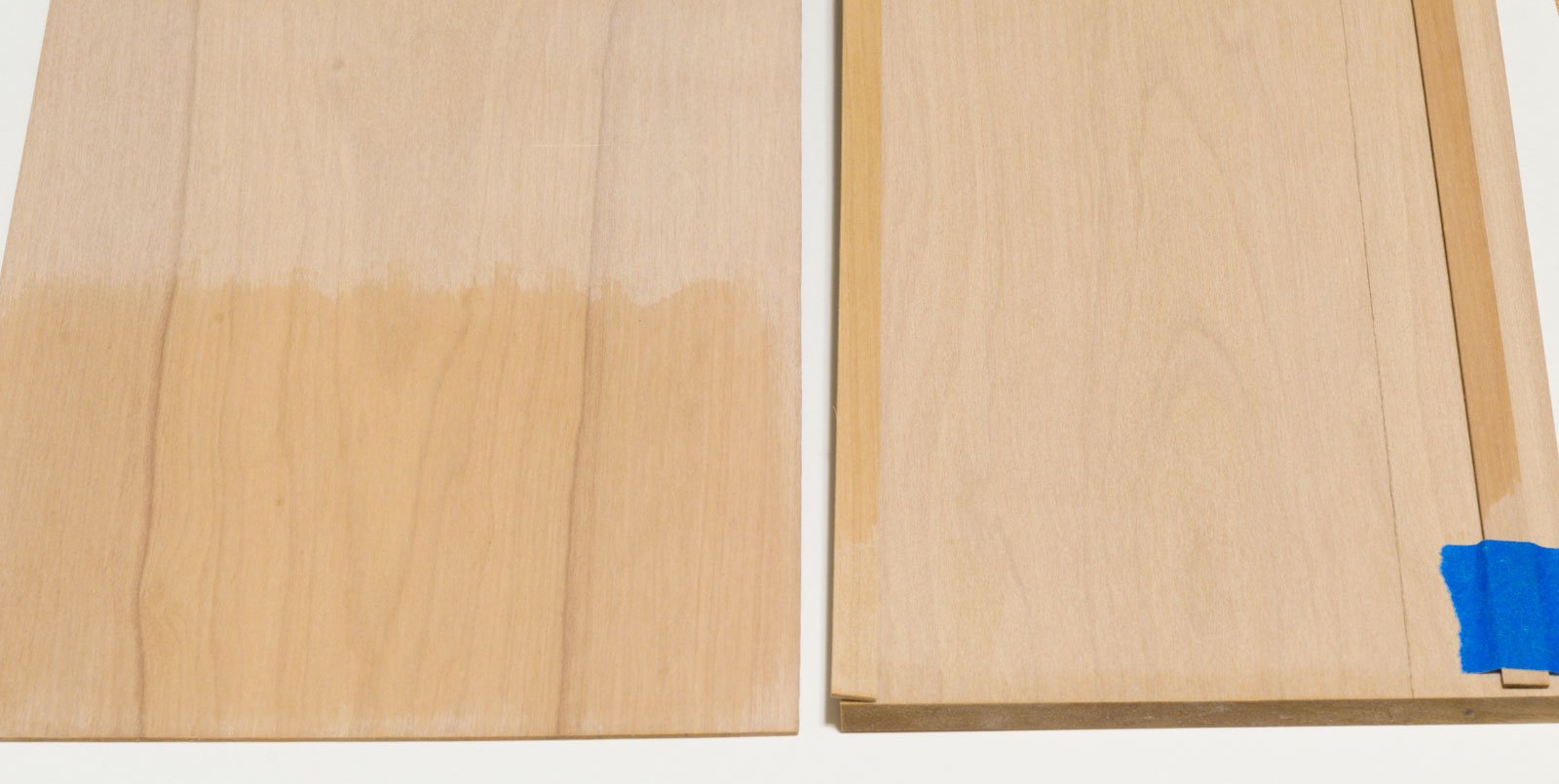
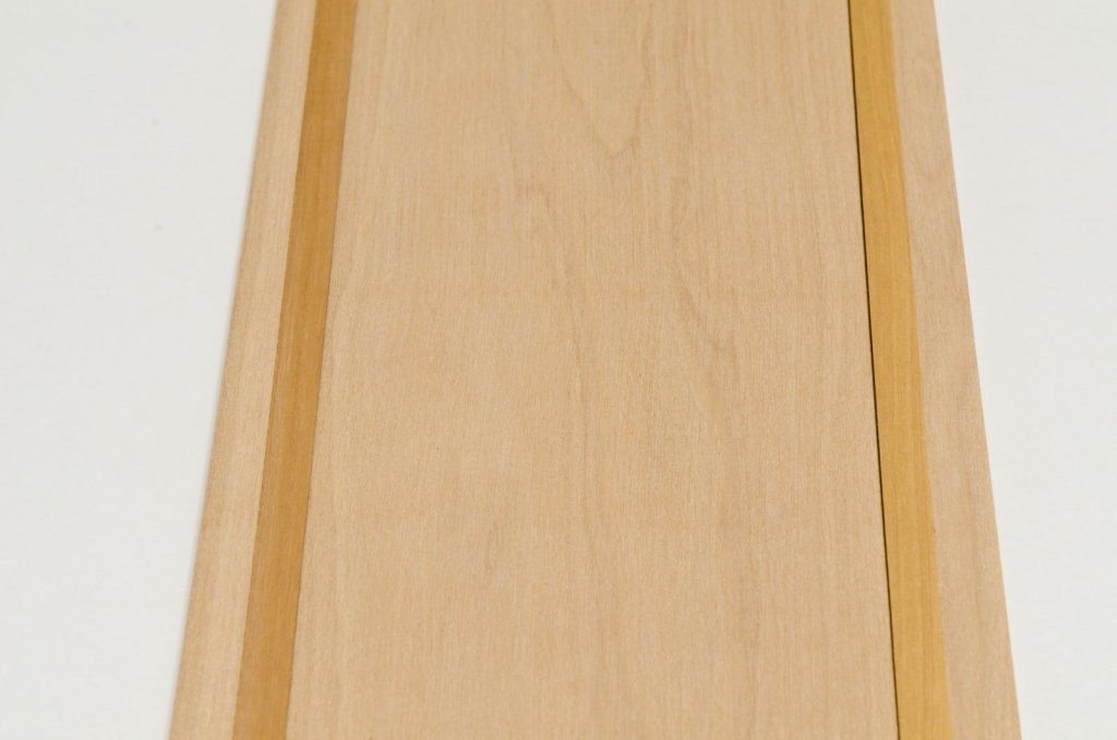
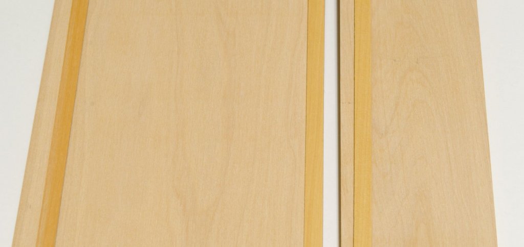
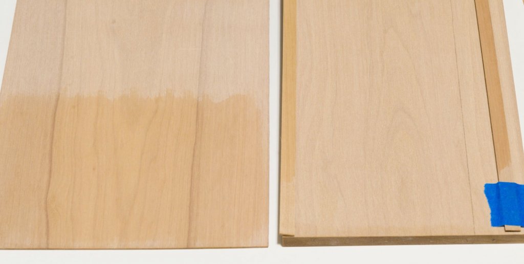
Its been a while, but before proceeding further I have decided to wait for Chuck to catch up to me. Design changes to the prototype build are inevitable and as much as I wanted to move ahead, I think it's best to wait. Meanwhile, I bought some 5" x 15" boxwood sheets from Chuck's supply that I thought would be a good match for the planking above the wales. I ripped a strip off each side and applied a coat of W-O-P to each strip. As you can see, the color can vary quite a bit from one side to the other. The darker grain in the sheet on the left side is harder to see than the photo would suggest. Here is the same sheet compared to the sheet I used for the upper hull planking which shows a good match on one side. The drop plank has to be made from 3/64" sheet due to its being so wide. Here again the W-O-P tells all. Using the outer area of the sheet should yield a reasonable match. It's a shame to have to discard some of this rather expensive wood, but I want to keep things as uniform as possible. Mike
- 607 replies
-
- 9
-
-
- winchelsea
- Syren Ship Model Company
- (and 1 more)
-
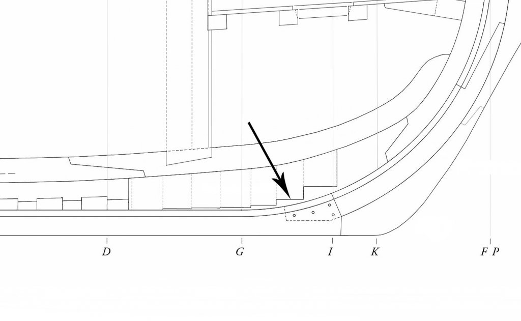
That's correct, Griphos. The deadwood is reduced from 15" to 12" at stepping line. That would be 1.5" or 1/32" "actual" removed from each side. Mike
-
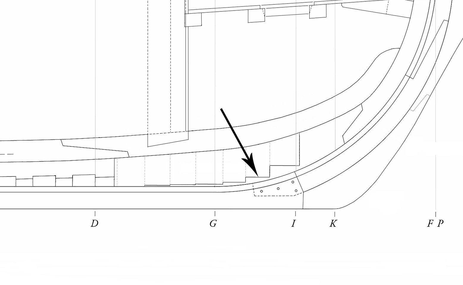
Shawn, Look again on plan sheet #1. Looks like this. . Mike
-
Tony, Right now things are on hold while I work on the Winchelsea. Mike
-
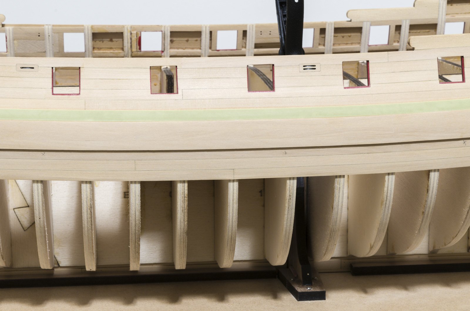
Thank you all for the comments and "Likes"! Here is a small update regarding the black strake installation and my somewhat lengthy method. I say that because I will do whatever I can to avoid having to paint the top edge of the strake where it overlaps the hull planking after it is glued down. Even if the area where masked off, I would question my ability to get a clean edge. The hull has to be prepared for any glue seepage that might occur. To do that I taped off a small area below and above where the top edge of the black strake is located. I applied a coat of W-O-P between the taped edges. I used some old striping tape that I had lying around. The top edge of the these planks are beveled and painted with Windsor and Newton "Mars Black" which has been thinned down considerably. Two coats is all that was needed. Once dry the remaining unpainted wood was masked off on both sides. A thin coat of Testors "Dullcote" was applied to the black paint which will protect the paint if glue seepage needs to be wiped off later. With the prep work completed, the planks can be glued onto the hull. I used a 1/8" flat paint brush trimmed very short to place a small bead of glue down the middle of the underlying hull planking. To avoid creating a mess each plank was glued its entire length in one shot. The end result is a clean edge where the black strake overlaps the hull planking. So far, with one side completed, there has been no glue seepage at all. There is no point in my painting the entire strake now since there are a number of steps that have to be completed before final painting. 1. Bevel the top edge of the wales 2. Install at least one strake below the wales which includes the drop plank. 3. Taper the wales towards its bottom edge for a pleasing transition into the strake below. Mike
- 607 replies
-
- 31
-
-
- winchelsea
- Syren Ship Model Company
- (and 1 more)
-
Mark, The cannons look really nice! Keep up the great work. Mike
-
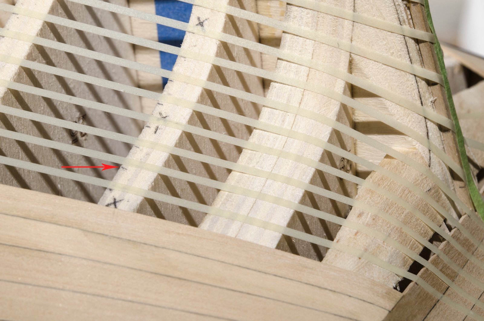
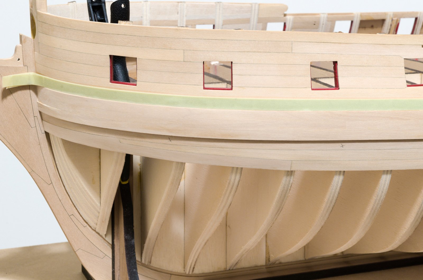
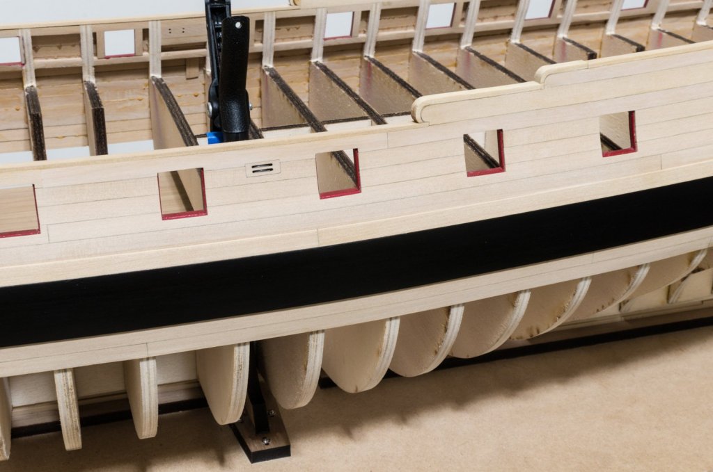
It seems like forever since I started on the second wale layer. Anyway, 3 of the 4 strakes are in. Each strake was made from 5 or 6 planks. I could do the last strake now, but I think it would be better to wait until at least one strake below the wale is in. This strake would include the drop plank at the fore end of the ship. Adding it now would give me a better visual for getting a good joint to the underlying wale layer and make it easier to sand it afterwards. I remember this issue coming up on the Cheerful build where I regretted not doing it this way. I could add the black strake now after doing a bit more sanding above it. The wale is tapered down to less that 1/64th at the stem from 3/4"-1" out. This was mostly done with a miniature chisel from Veritas. https://www.fine-tools.com/miniature-chisels.html I left one layer untouched, so you can better see this. Mike

- 607 replies
-
- 32
-
-
- winchelsea
- Syren Ship Model Company
- (and 1 more)
-
Very nicely done, Mark! Mike