HOLIDAY DONATION DRIVE - SUPPORT MSW - DO YOUR PART TO KEEP THIS GREAT FORUM GOING!
×


Stuntflyer
-
Posts
1,197 -
Joined
-
Last visited
Content Type
Profiles
Forums
Gallery
Events
Everything posted by Stuntflyer
-
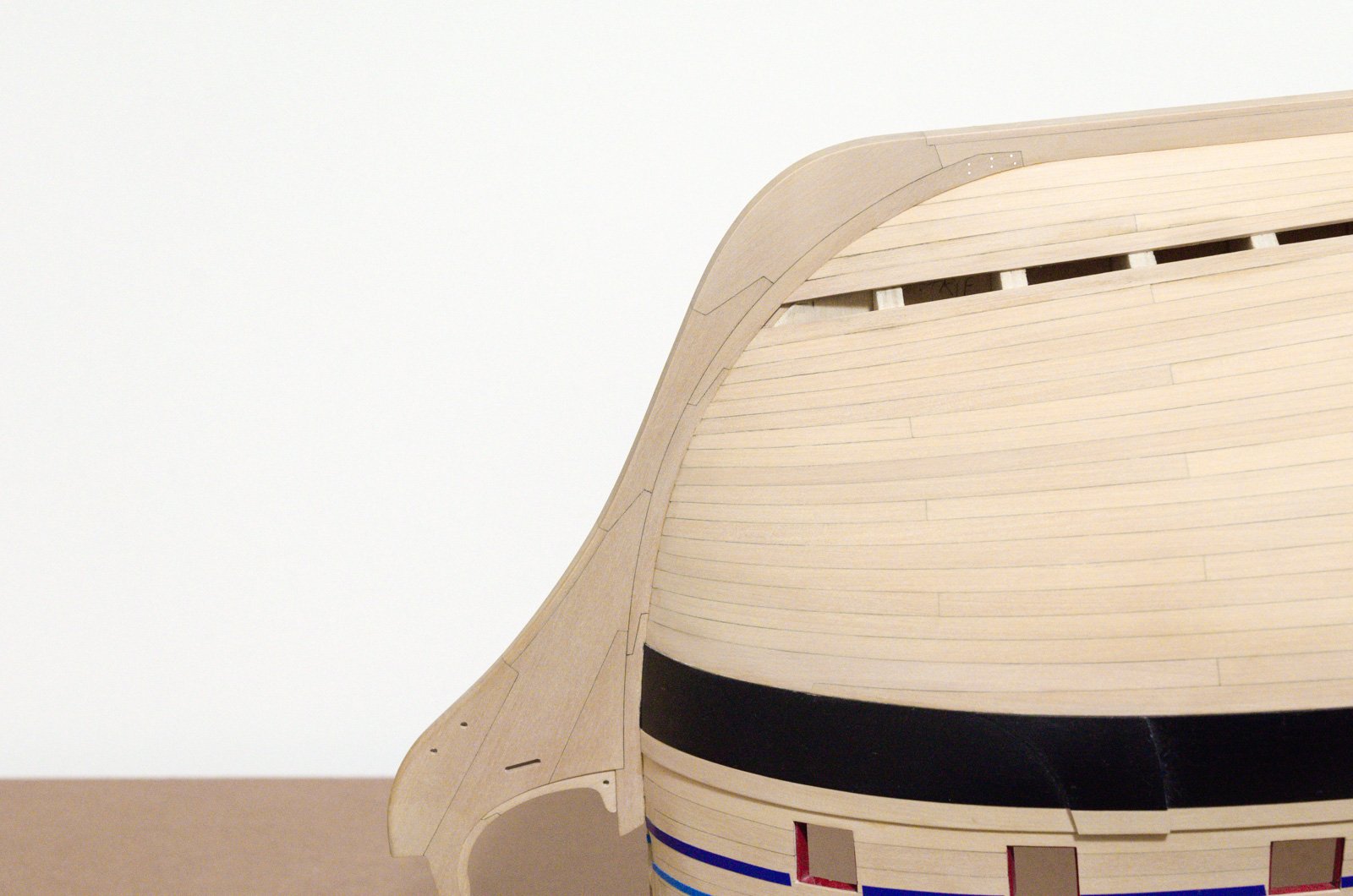
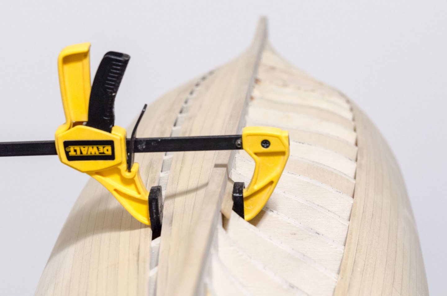
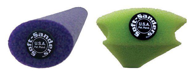
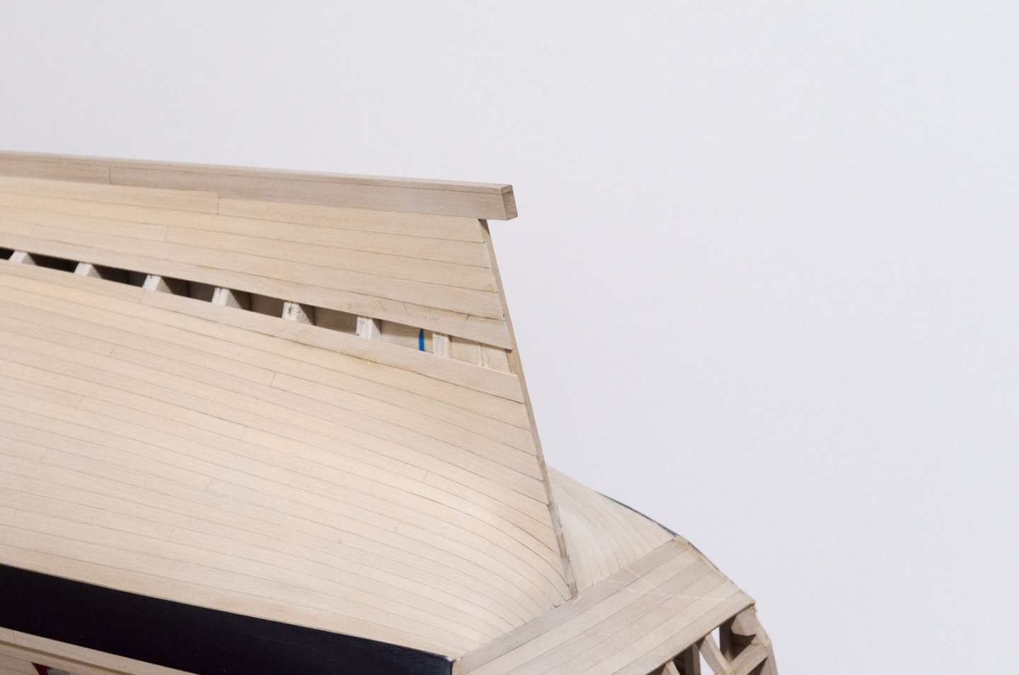
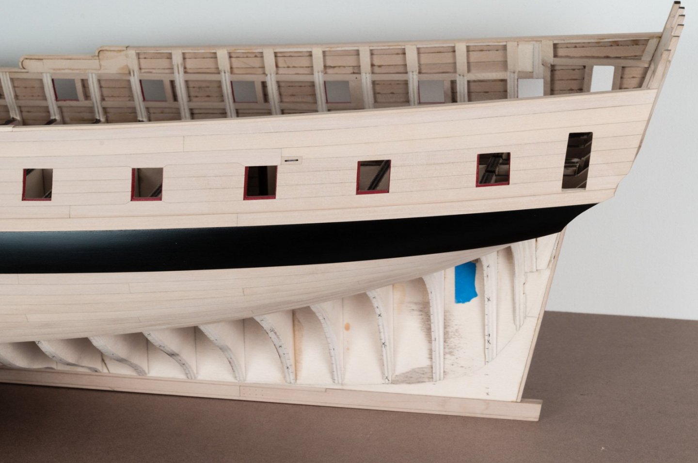
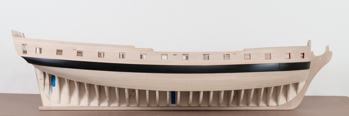
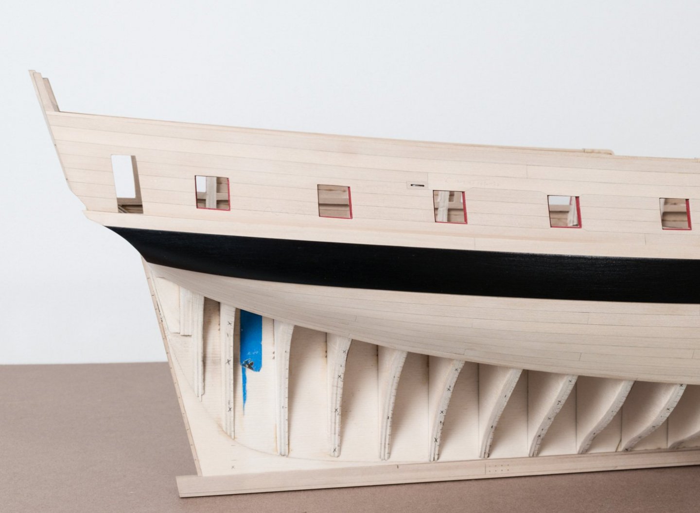
 Hello and a Happy New year to everyone! I've been making some progress on the hull planking. The last two belts on the starboard side minus one strake are done. As tempting as it was to add the last strake I knew that I would still need a clamping area to adhere to when I start again on the port side. Clamping against the keel doesn't work since the angle of the clamp would pull the plank up and away from the bulkhead. Moving the clamp down five strakes changes the angle of the clamp just enough to hold the plank tight against the bulkhead. I've added a few photos showing the planking detail both fore and aft. All of the sanding so far has been done with Soft Sanders. They are hard foam shapes that you wrap with adhesive backed sandpaper which is supplied by the company. The sandpaper lasts forever it seems. I am using 180 and 320 grit. http://www.softsanders.com/products/wood. I find that these two shapes work well. I cut them into 3" to 5" lengths. They conform to the hull shape allowing for a smooth transition when sanding. Mike
- 607 replies
-
- 22
-

-
- winchelsea
- Syren Ship Model Company
- (and 1 more)
-
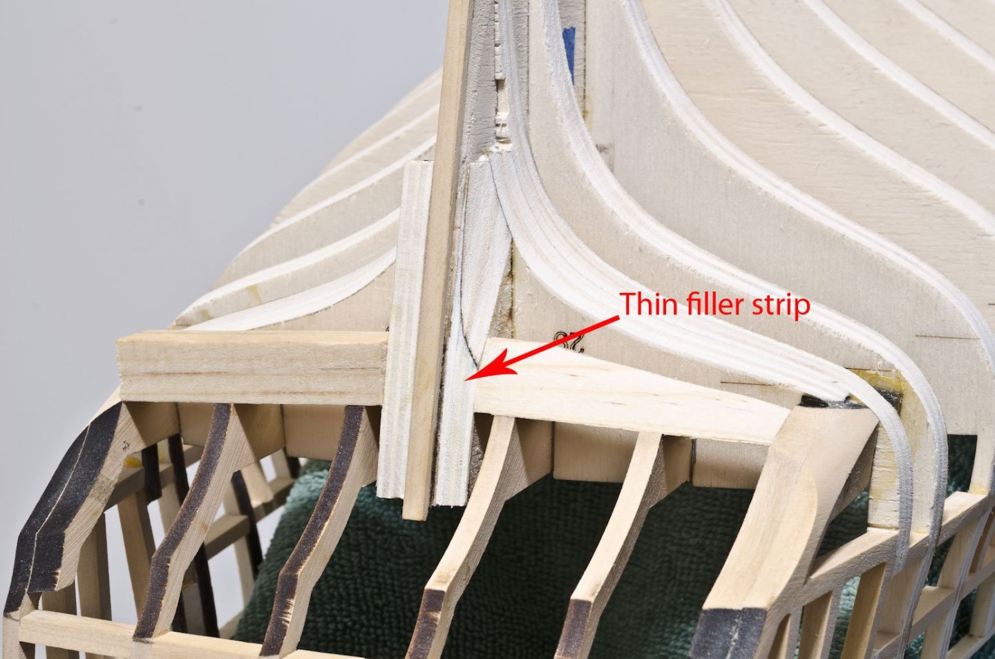
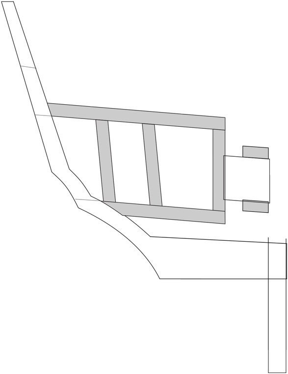
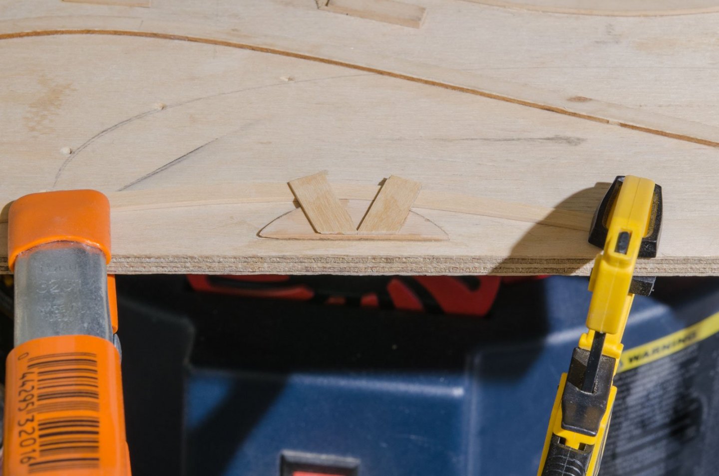
Regarding the two stern filler pieces, here are mine installed. Hope this helps. Mike
-
Nice work, Chuck! I know you're still undecided, but I'm leaning now towards the blue-gray slate roof rather than natural. Mike
- 1,784 replies
-
- 4
-
-
- winchelsea
- Syren Ship Model Company
- (and 1 more)
-
Chuck, you're doing a great job on the QGalleries. Very methodical and neatly done. Did you manage to straighten out the frieze with the name? How is the tissue paper working out? Mike
- 1,784 replies
-
- 1
-
-
- winchelsea
- Syren Ship Model Company
- (and 1 more)
-
Love it, Chuck! Could the moldings be added after the frieze is in place in order to hide frieze edge? Mike
- 1,784 replies
-
- 1
-
-
- winchelsea
- Syren Ship Model Company
- (and 1 more)
-
Yes, the molding sits on top of the planking. Mike
- 607 replies
-
- 1
-
-
- winchelsea
- Syren Ship Model Company
- (and 1 more)
-
Rusty, Check the vertical timbers as well. Not sure how much it matters, but 2 of them are parallel to each other. Mike
- 642 replies
-
- 6
-
-
- winchelsea
- Syren Ship Model Company
- (and 1 more)
-
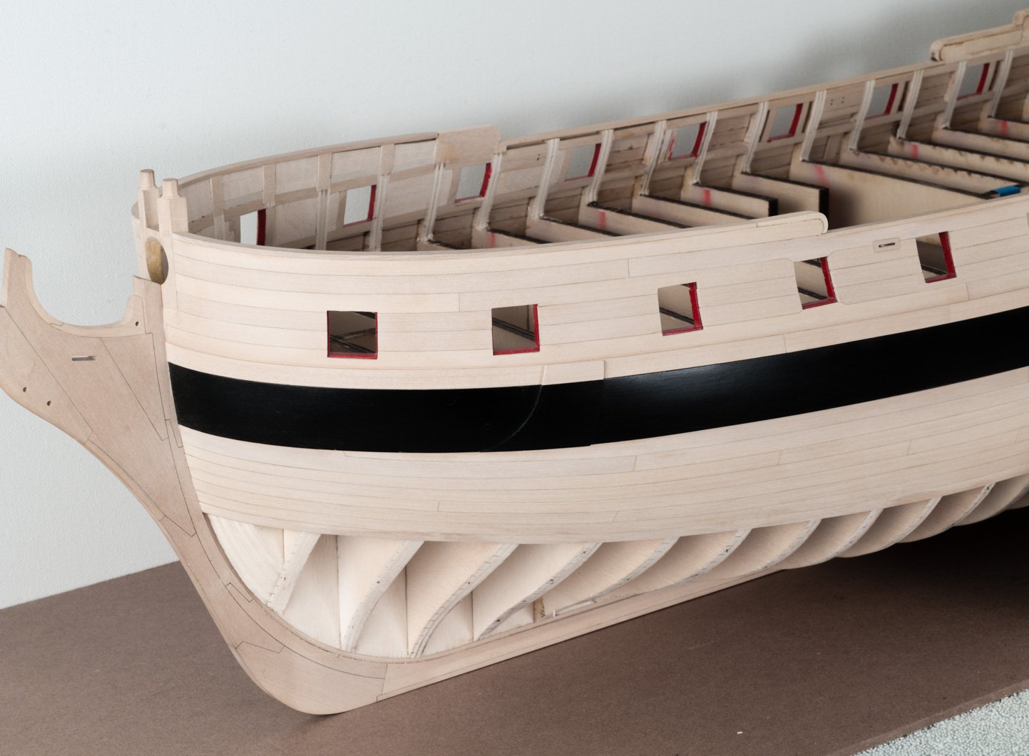
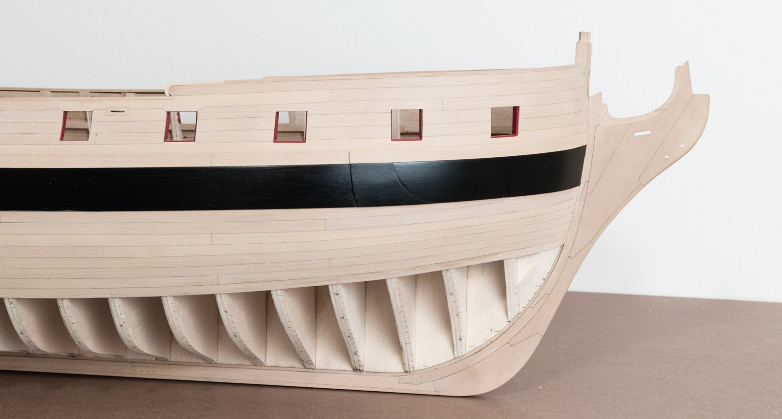
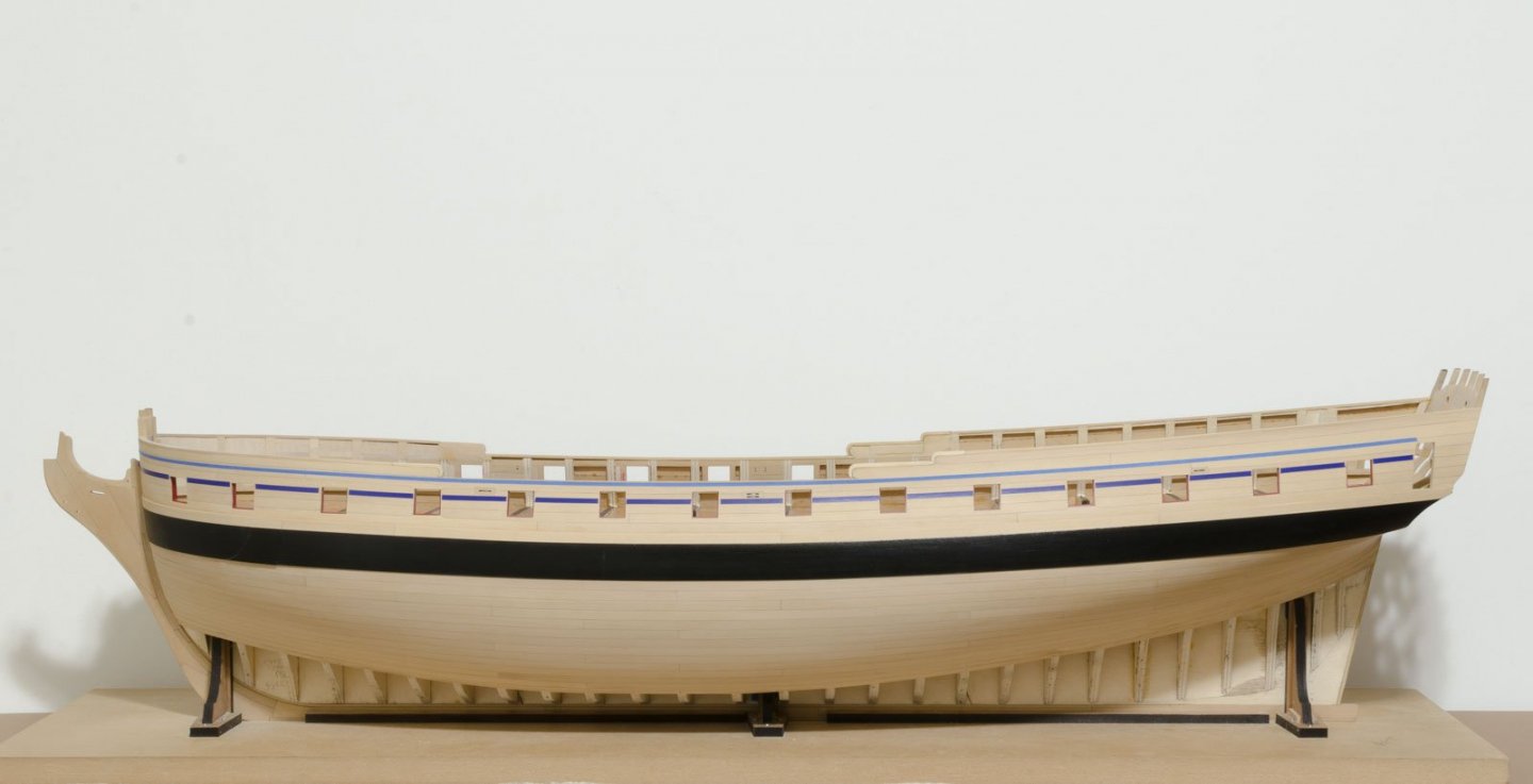
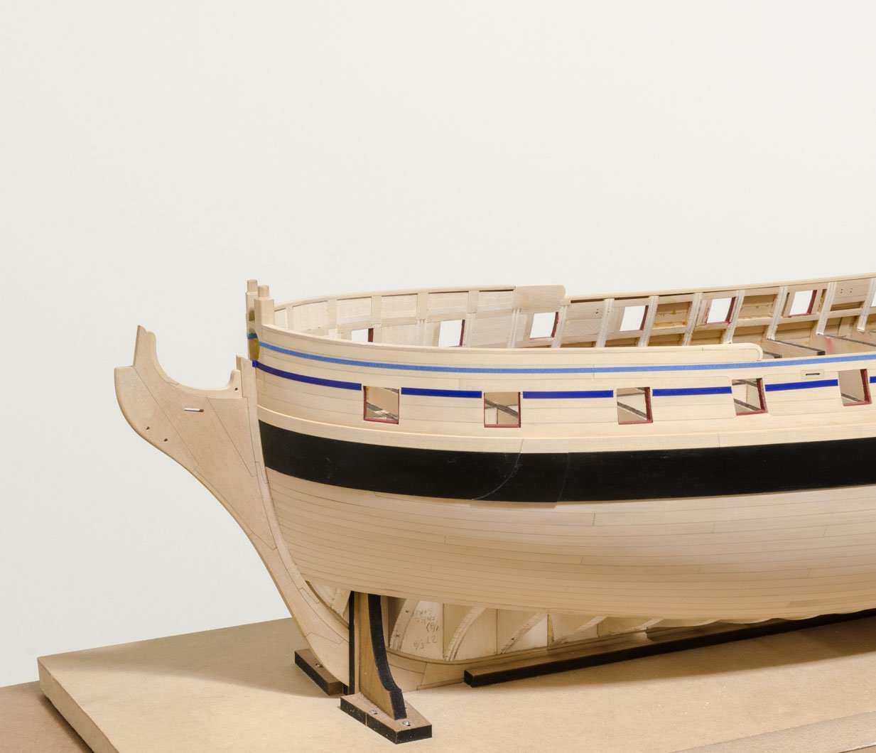
The second planking belt, now completed, has proven to be the most difficult one to do so far. I'm told that the last two belts will be much easier to complete which is good news. After seeing Chuck's taped off molding bands that run both through and above the gun ports, I was very curious as to how this would look on my ship. I wanted to know if the gun ports, fixed blocks and sheer were correct. Using measurements taken off the plan drawing I transferred the lower molding position onto the hull (turns out that the lower molding runs parallel to the wales). 1/8" tape was placed onto the hull to simulate the lower molding that runs through the gun ports. After eyeing the run from several positions I could see that some very slight tweaking was needed in order to establish a smooth run. Once satisfied, I added the simulated 3/32" upper molding which runs parallel to the lower molding. I was happy to see that both sides of the hull are almost identical with regard to gun port placement as well as sheer height and shape. Mike
- 607 replies
-
- 24
-
-
- winchelsea
- Syren Ship Model Company
- (and 1 more)
-
Nicely done, Chuck! Thanks for the heads up on the molding strip widths and using tape to establish a proper run for each. You've peaked my interest in knowing how accurately I have planked that upper section. Mike
- 1,784 replies
-
- 2
-
-
- winchelsea
- Syren Ship Model Company
- (and 1 more)
-
I saw Chuck's Winni last week at the house and it looks even better than the photos. . . Mike
- 1,784 replies
-
- 5
-
-
- winchelsea
- Syren Ship Model Company
- (and 1 more)
-
Joe, here are my findings regarding the planks going into the stem. . 1. Bevel the outside edge that goes into the stem as well as the inside edge. I find that it's the best way to hide the inside edge of the stem, leaving a nice transition between the plank and stem. 2. I have not found it necessary to bend the plank along its length around a "canister cap" or other round shape. I Just edge bend the plank enough so that its edge conforms nicely to the plank below while at the same time hugging the bulkheads that it crosses. Mike
- 1,784 replies
-
- 6
-
-
- winchelsea
- Syren Ship Model Company
- (and 1 more)
-
Chuck, beautiful work as always. I'm a bit behind you on my planking and that's a good thing. Your photos are very helpful, but as always make things seem easier than they really are. Now would be a great time for all those building the Winni to chime in on some of Chuck's expertise in planking techniques. Mike
- 1,784 replies
-
- 5
-
-
- winchelsea
- Syren Ship Model Company
- (and 1 more)
-
Looking very nice, Bob. Something that I almost forgot to do was to check the stern framing angle off the plan. Initially I was relying on how the frames sat in the bulkheads. Mike
-
Yes, Joe, I use a 1 3/8" dowel or hard plastic container to curve the plank along its length. Just dampen, clamp and heat with a hair dryer. The curve can be finessed by hand afterwards. Mike
- 607 replies
-
- 2
-
-
- winchelsea
- Syren Ship Model Company
- (and 1 more)
-
Thank you all for the kind words and "Likes". Very much appreciated as always. Mike
- 607 replies
-
- 3
-
-
- winchelsea
- Syren Ship Model Company
- (and 1 more)
-
Work is now completed on the second belt. Not much to say other than more of the same. Just some cleanup sanding and as always I try to avoid sanding too much of the last few installed strakes. The knee is getting a bit grungy due to excessive handling, though not a problem to clean up later. Mike

- 607 replies
-
- 36
-
-
- winchelsea
- Syren Ship Model Company
- (and 1 more)
-
Dave, You're off to a great start. I suggest that you can cut the inside bulkhead extensions, extension tops and the area of the false deck to the line, being careful that the line shows afterwards. You will take off more material on the inside extensions when you fair the hull inside. The false deck area will be much easier to sand or file now rather than after the bulkheads are glued to the bulkhead former. Mike
-
Looks very familiar, Bob. Glad to see that your up and running. I think you will really enjoy building the Winni. Mike
-
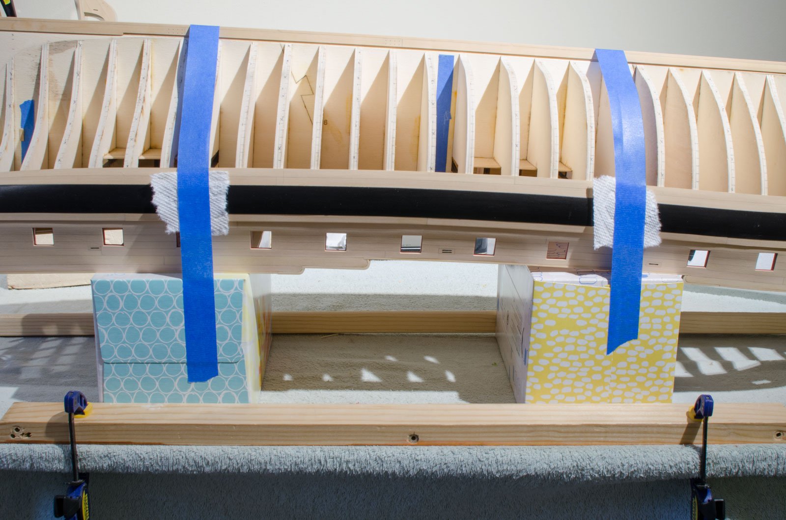
This is how I hold the hull steady while planking below the wales. I can slide the Kleenex boxes left or right depending on what section of the hull I'm working on. The painters tape can be released and reapplied several times before losing adhesion. I've been using this edge bending jig since my 18th Century Longboat build. Recently I adapted this variation on Chuck's center hold down. Mike

- 607 replies
-
- 19
-
-
- winchelsea
- Syren Ship Model Company
- (and 1 more)
-
I glue each plank to the bulkheads and as well as the adjacent planks. Mike
- 607 replies
-
- 1
-
-
- winchelsea
- Syren Ship Model Company
- (and 1 more)
-
Thanks, Rusty! I'm looking forward to seeing your progress on your "new" Winchelsea build. Mike
- 607 replies
-
- 3
-
-
- winchelsea
- Syren Ship Model Company
- (and 1 more)
-
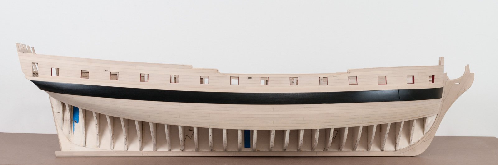
Planking below the wales is one of my favorite parts of the build. I have now completed the first belt on the starboard side. Working with boxwood is great though I have to work slowly if I want to get a nice result. On a good day I can complete one strake. I'm Just taking my time and treating each plank as a project in itself. Edge bending is my new friend and I'm finding, for the most part, it's all that is needed. The exception being where the plank sweeps upwards into the counter. There I use a dowel to form the shape. In all cases I use the hair dryer after wetting the wood for 10-15 seconds. Some preliminary cleanup sanding was done while leaving the last installed strake mostly untouched until more planks are added below it. Mike

- 607 replies
-
- 33
-
-
- winchelsea
- Syren Ship Model Company
- (and 1 more)
-
I don't know about that, Boyd. .5mm seems like a lot to be off by, but perhaps you will be okay. Good luck! Mike
-
Nice fix, Matthias! Mike