Stuntflyer
-
Posts
1,198 -
Joined
-
Last visited
Content Type
Profiles
Forums
Gallery
Events
Everything posted by Stuntflyer
-
 Welcome aboard, Tom. Looks like I'm going to learn a lot of new things from your Winnie build. I'm looking forward to that. Mike
 -
Bill, You should be very proud of what you have accomplished here. Cheerful is not an easy build at all and you did a great job. Well done!! Mike
- 54 replies
-
- 2
-

-
- cheerful
- Syren Ship Model Company
- (and 1 more)
-
Thank you all for the kind words and for all the "Likes". Yes, for sure. Mostly because I was worried about having to ask Chuck to make another one for me. 😟
- 607 replies
-
- 2
-
-
- winchelsea
- Syren Ship Model Company
- (and 1 more)
-
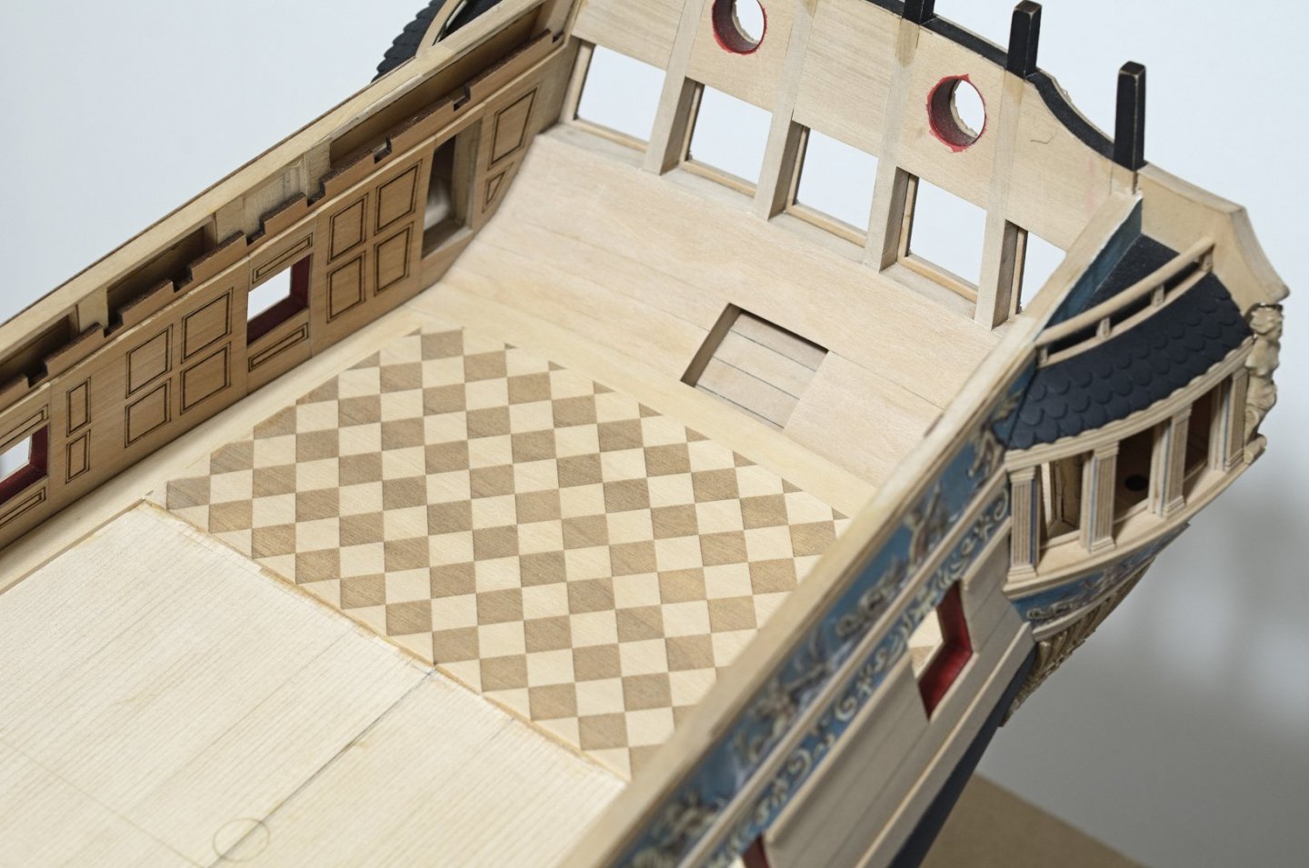
That's a very good idea, though there is one thing that I should mention. The laser char on the checkerboard floor can easily smudge or lighten if not handled properly. I think that it should remain untouched. So, I would use your idea under other circumstances, but would be afraid to use it here. Mike
- 607 replies
-
- 3
-
-
- winchelsea
- Syren Ship Model Company
- (and 1 more)
-
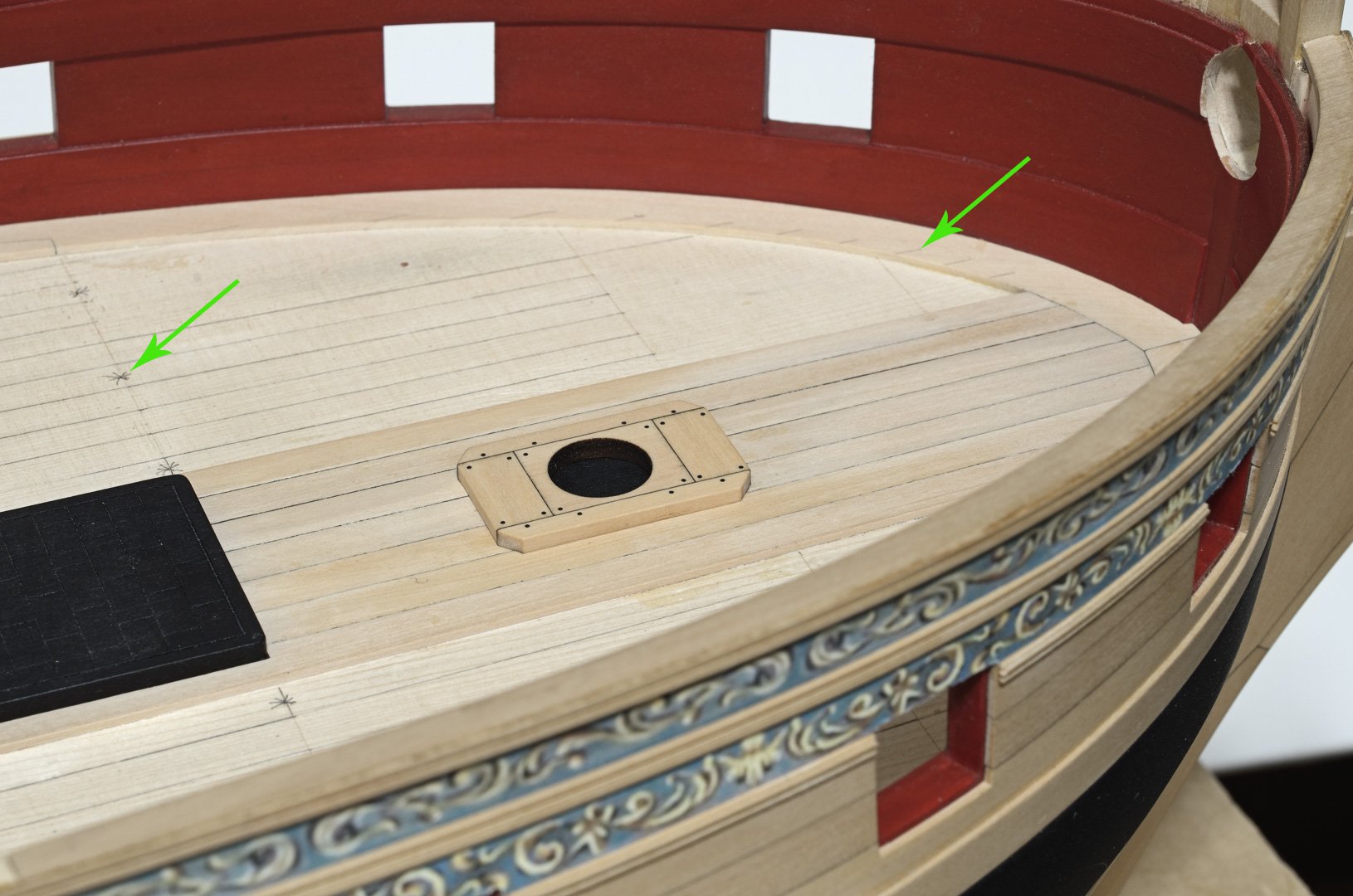
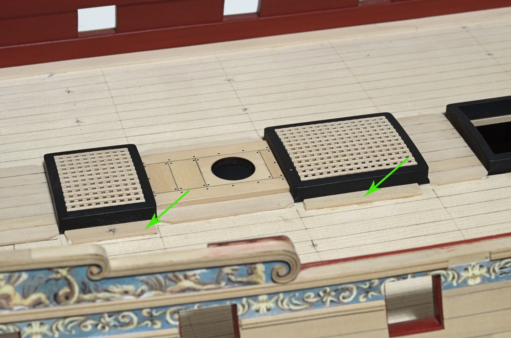
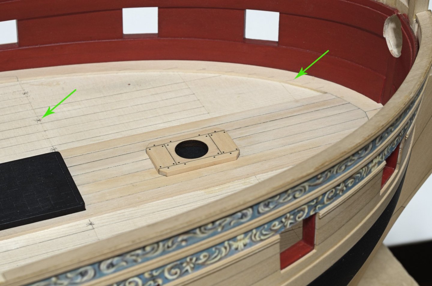
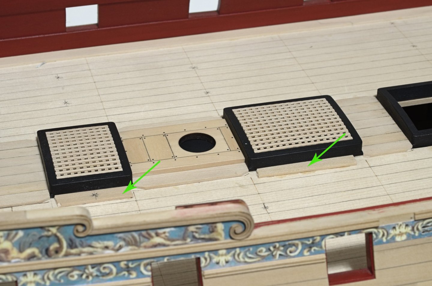
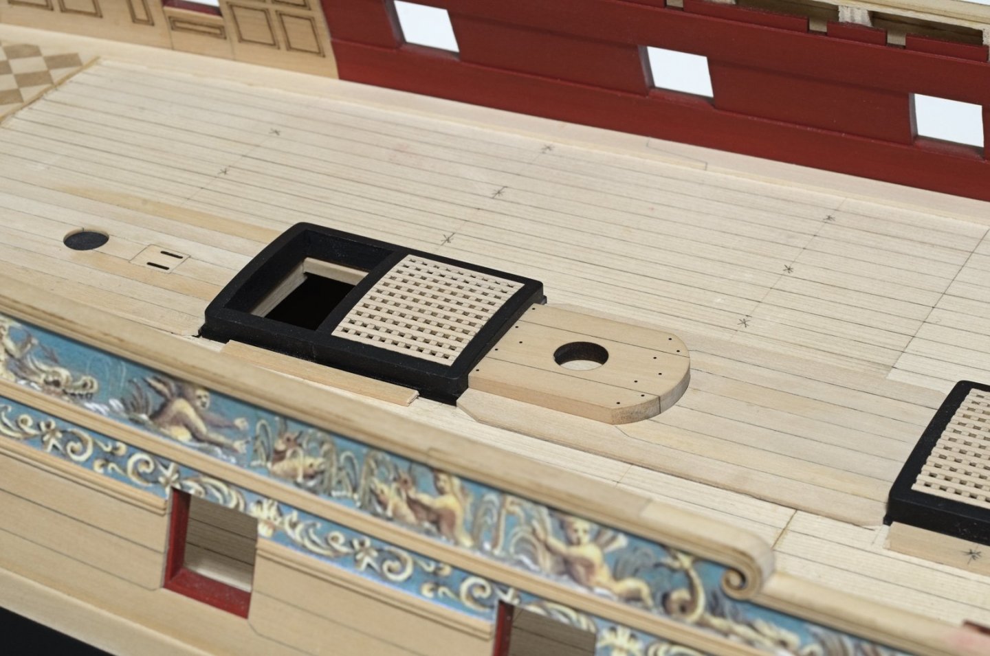
Happy New Year everyone😁 I've started on the deck planking, completing the first belt and the lining off the remaining two belts. The planking remains unsanded and looking dirty and discolored at the moment. The only cleanup was to scrape most of the PVA off the joints after gluing. The final cleanup will come later as I move onto the second belt. There will be more room to sand without the risk of knocking down the outside plank edges. All of the deck fittings are removable as well which will make things a whole lot easier. I extended the line onto the margin plank after lining off and I also marked where the butt joints are located. I glued some short alignment strips to the deck and up against the fixtures to keep them centered on the deck For the mast partner bolts I used some 20lb black monofilament drilled with a #76 bit. No gluing necessary. I almost got into deep trouble when I tried gluing the cabin floor with PVA. It started to warp quickly and being boxwood made it hard to bend back. Luckily I was able to get it into position and down tight to the false deck, albeit with a few sore fingers. Stay with medium CA on this one. Trust me! Mike
- 607 replies
-
- 29
-
-
- winchelsea
- Syren Ship Model Company
- (and 1 more)
-
Very nice, Chuck. You're doing all the hard work while making things super easy for the rest of us. Mike
- 1,784 replies
-
- 2
-
-
- winchelsea
- Syren Ship Model Company
- (and 1 more)
-
Awesome work! Mike
-
Moving along nicely, Matt. Keep up the good work. Mike
-
Looking great, Chuck! Interesting that you did the hinges and straps in two pieces. I guess the Cheerful way, where a strap was wrapped around hinge, would not have worked. Mike
- 1,784 replies
-
- 2
-
-
- winchelsea
- Syren Ship Model Company
- (and 1 more)
-
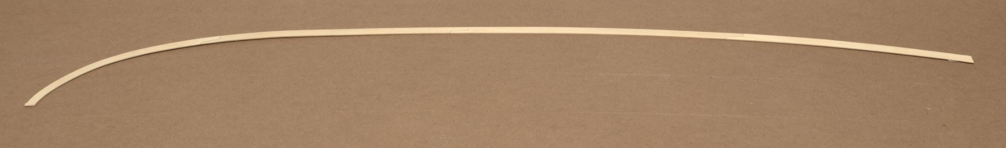
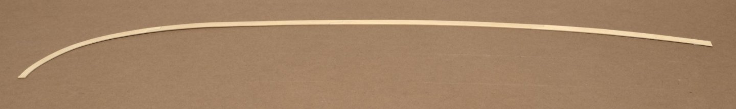
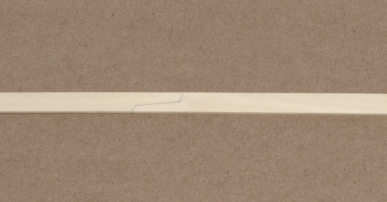
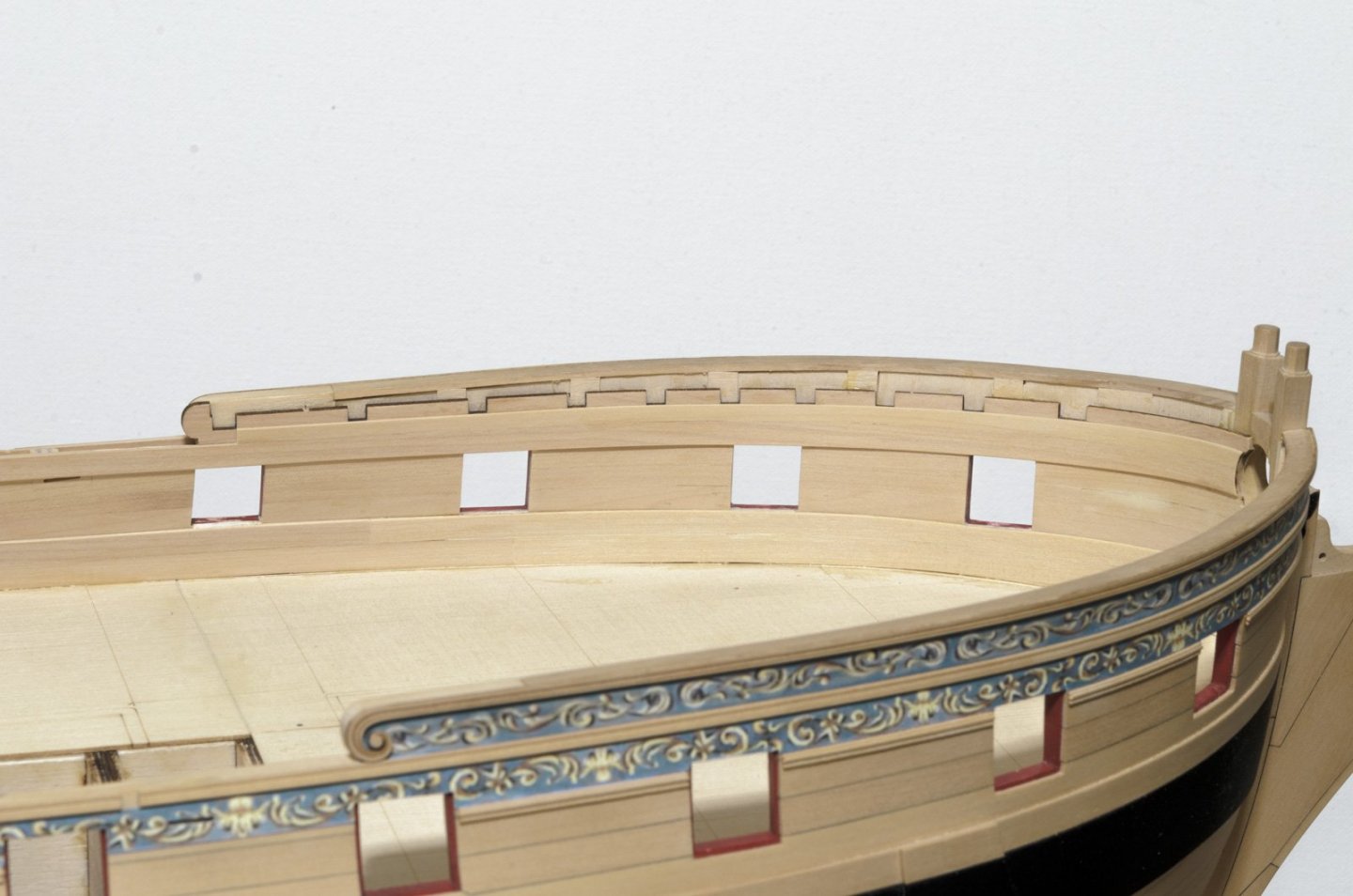
Happy Thanksgiving! 🦃 I've completed work on the starboard side margin planks which are made up of four sections joined by scarf joints. I decided to join all four sections together first, rather than adding them to the ship individually. The idea was to get really tight joints while still being able to maintain the proper shape along the bulwarks. That would mean using a light box or a window in daylight to check the joint fit. All of the sections were cut wider than the provided template to allow for any custom shaping that might be needed. I started with the first section at the bow by shaping the outer edge and making the scarf joint. Once completed, I shaped the next section without making the forward scarf joint. Both sections were placed along the hull and overlapped where the joint was located. I marked the joint shape with a sharp pencil and once satisfied with the fit, joined the two sections together. The same steps were carried out for the next two sections until all four sections were joined together. I used a compass to scribe the inner edge width of the margin plank and drum sanded it to complete the new shape. Lastly, I final sanded the inner edge to a smooth shape and a 90° edge. Everything went smoothly. I just needed to be careful when handling the joined lengths which is over 30". The easiest part was gluing the completed work to the hull. To speed up glue application I used a glue syringe to apply a small bead of PVA glue over its entire length. Mike

- 607 replies
-
- 23
-
-
- winchelsea
- Syren Ship Model Company
- (and 1 more)
-
Check the height of the rail on the plan sheet. That should tell you where you need to be. Mike
-
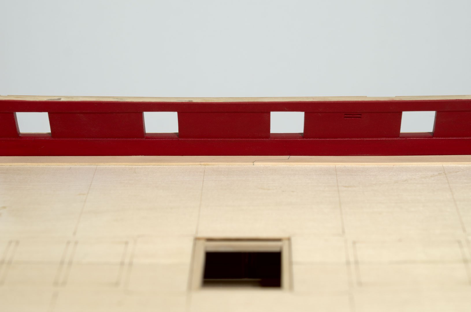
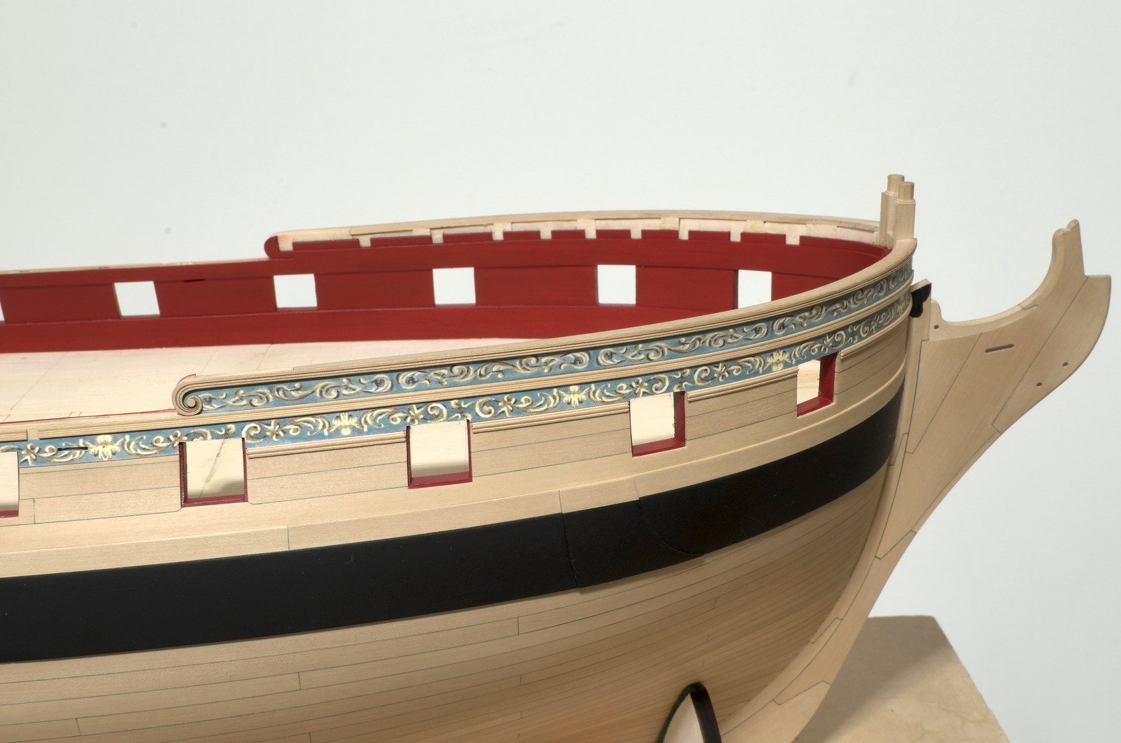
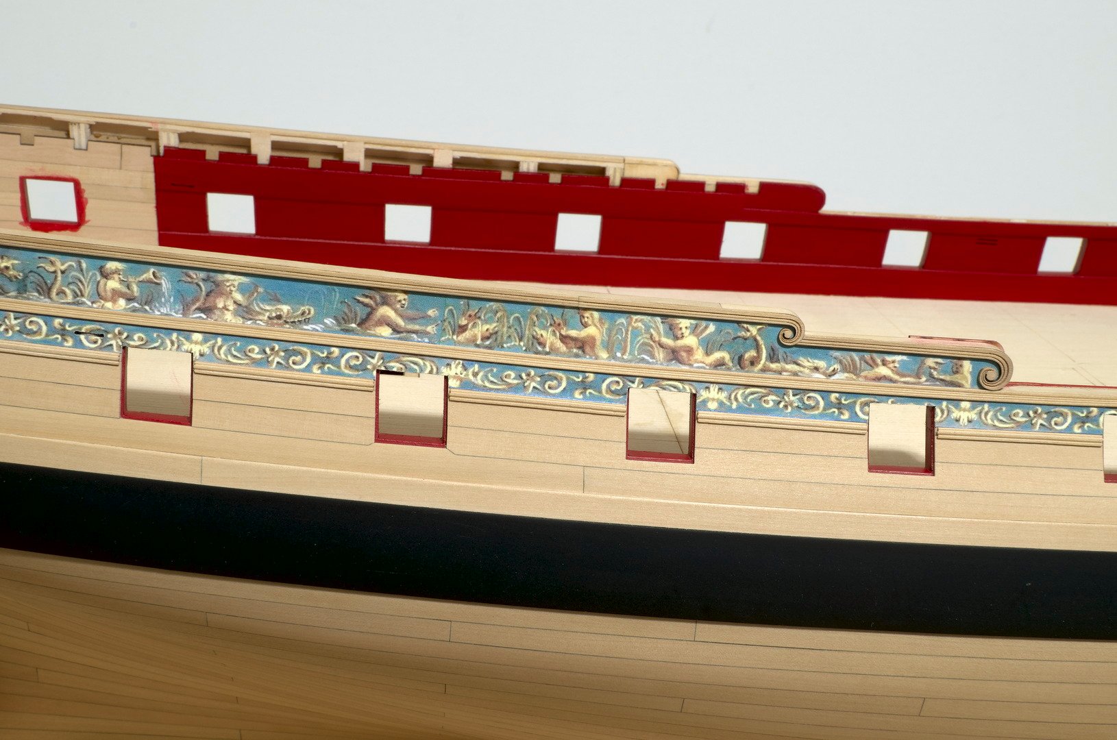
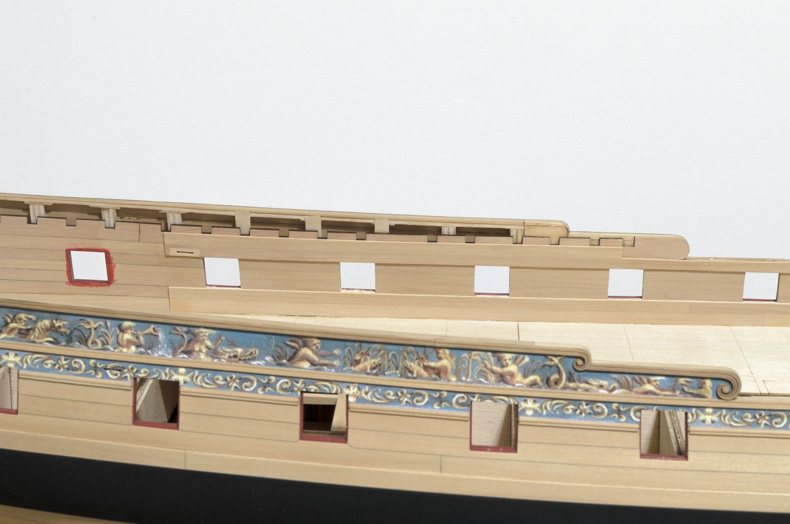
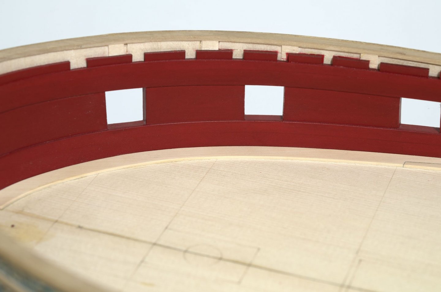
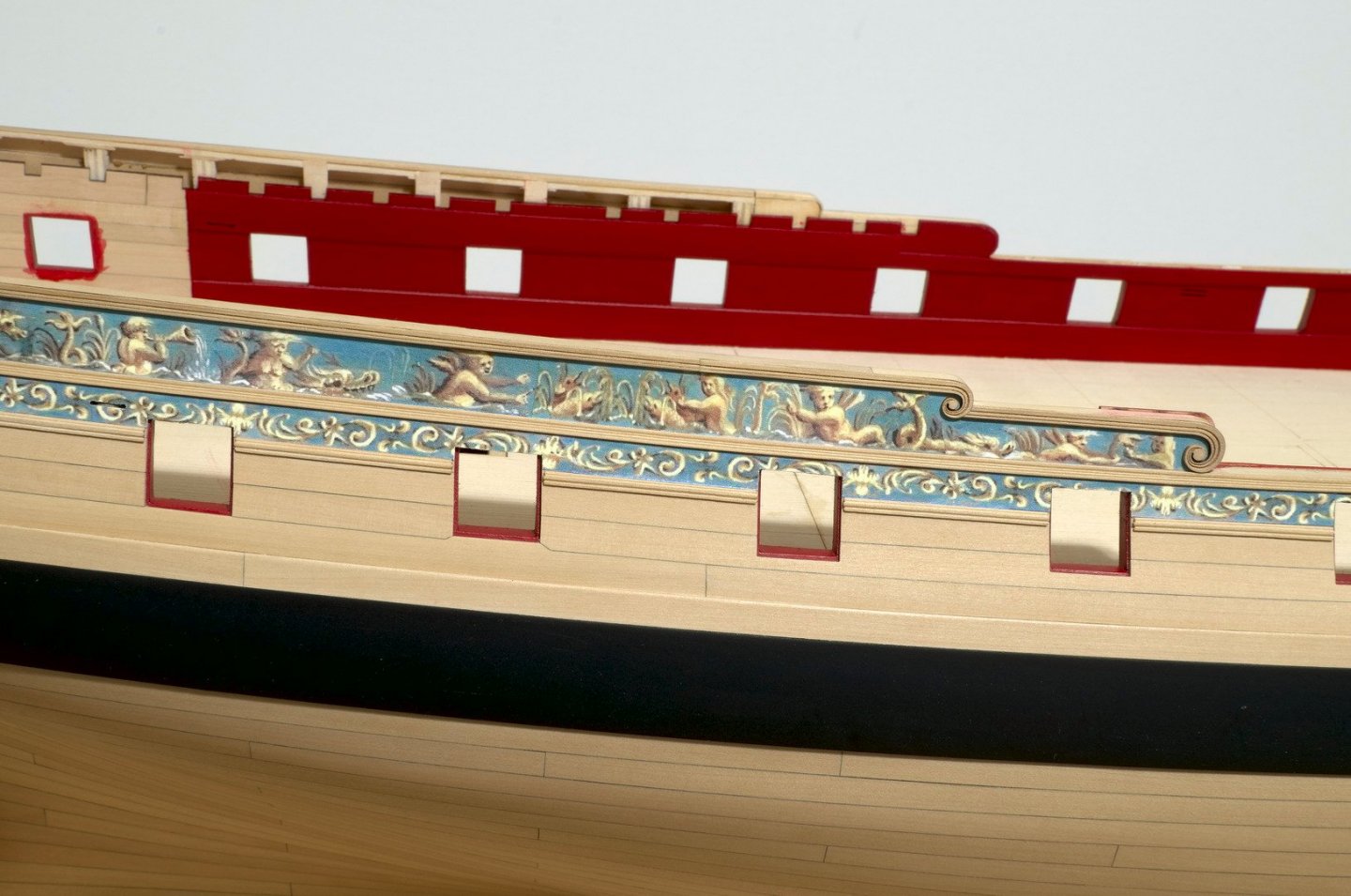
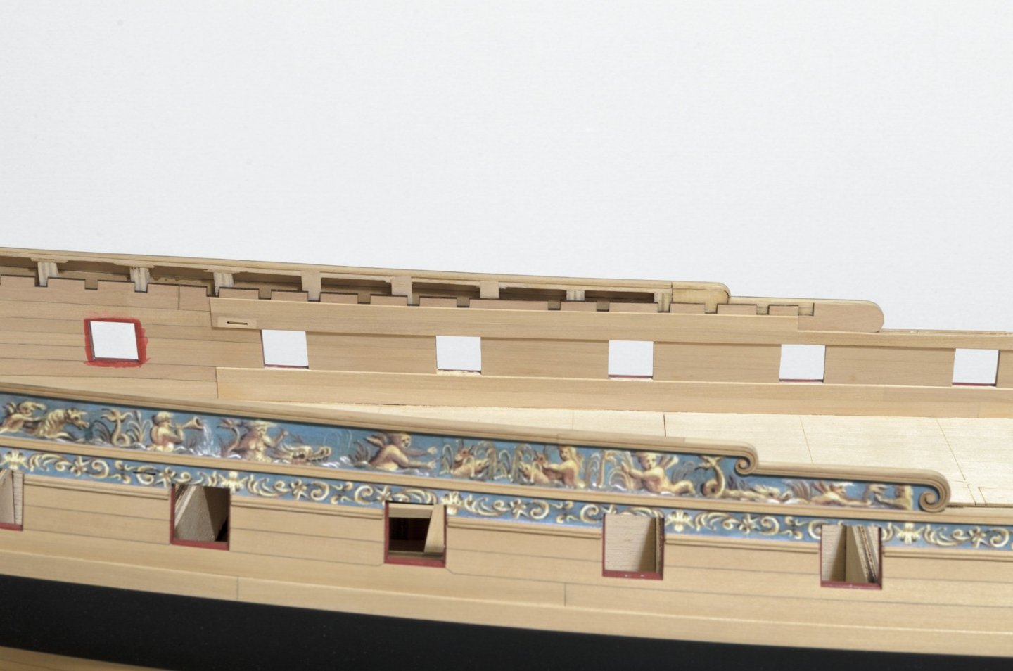
Seems like forever since my last post. After completing the starboard side bulwark planking and spirketting I painted everything red. To prep for the paint work each gun port was sealed on both sides with thin pieces of soft foam cut from weather sealing, typically bundled with window air conditioners. I figured that if I did both sides of each port that it would remove any chance of paint over spray messing things up. Cutting the foam pieces goes quickly with a #26 X-ACTO blade. The most time consuming part was the taping of deck clamps, etc. Once done, the painting goes quickly. I mixed W&N Crimson and Burnt Umber in a ratio of 10 to 1 respectively. I applied 10 thinned brushed coats followed by 7 or 8 spray coats. There was no way of knowing how it would all turn out until all the foam and tape was finally removed. Luckily everything was clean with no touch up needed. Mike

- 607 replies
-
- 33
-
-
- winchelsea
- Syren Ship Model Company
- (and 1 more)
-
Nice progress, Rusty. The poly really brings out those deck colors. I'm curious though if there was a reason for your not painting the QD clamp. Mike
- 642 replies
-
- 2
-
-
- winchelsea
- Syren Ship Model Company
- (and 1 more)
-
Sooner or later you will have to know where you are going to place those gammoning holes. Might be a good idea to figure it out now and commit to doing it while it is easier to accomplish. Mike
-
Wes, I'm Just curious as to why you wouldn't have done the gammoning holes prior to tapering the stem Mike
-
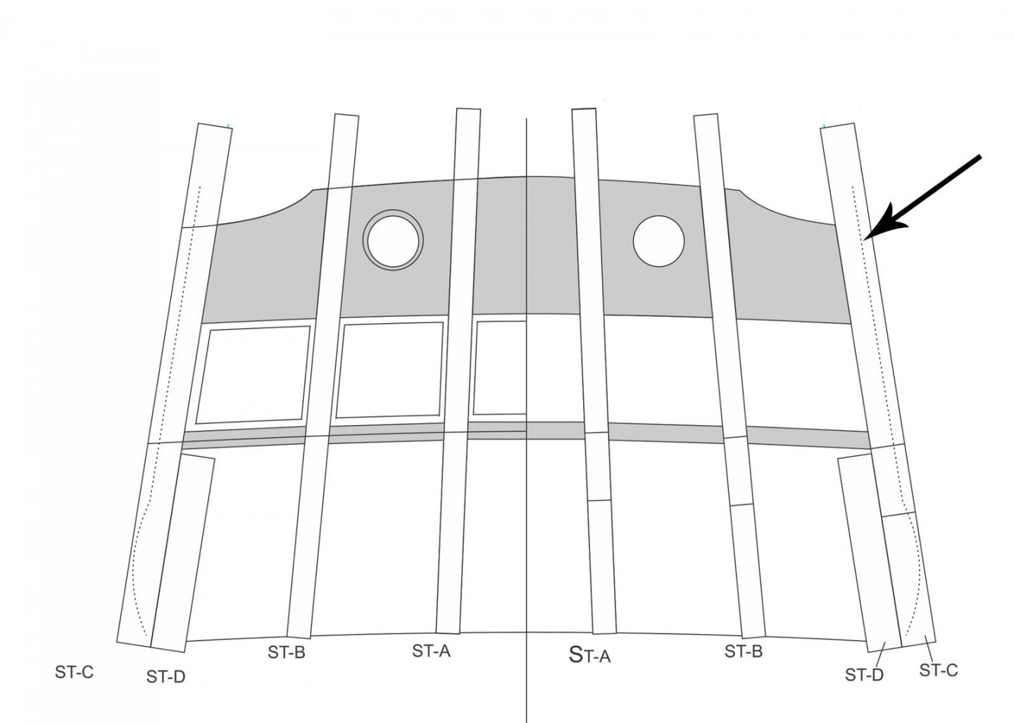
Greg, just a small reminder to fair the outer stern frames as shown here by the dotted lies. Mike
-
Nice fix, Scott. Well worth the effort. Mike
-
There is something I forgot to mention with regard to fairing the inner hull. If you want the bulkhead paneling to sit flush with the stern frames inner edge, then leave room for that. I left about 5/64". The panel height will not go above the height of the window opening. Mike
- 607 replies
-
- 10
-
-
- winchelsea
- Syren Ship Model Company
- (and 1 more)
-
Thank you Thomas for the kind words. Always appreciated! Mike
- 607 replies
-
- 1
-
-
- winchelsea
- Syren Ship Model Company
- (and 1 more)
-
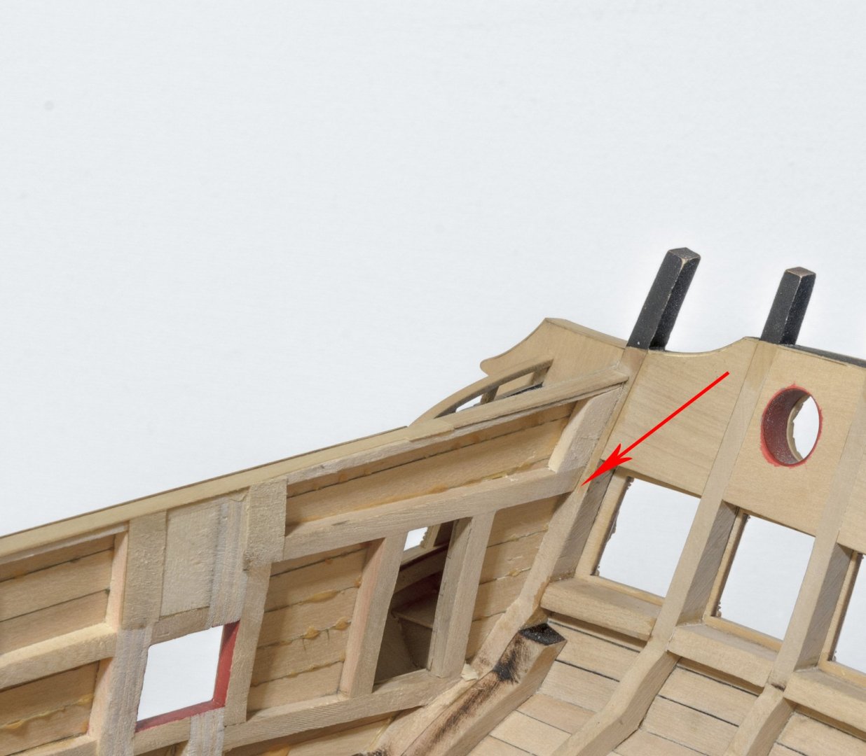
I've been working on chapter four, port side. The filler piece for the hawse hole, bulwark planking, fixed blocks, spirketting and deck clamps are completed. It was my goal to get the overall width at the waste no wider than 9/32" (13.5"). The first task was to finish the inner bulkhead fairing. I opted to sand the bulkheads, gun ports, etc. down to 1/8" all the way to the false deck. Another option would have been to taper everything gradually to 1/8". Chuck would know more about this, I'm sure. Anyway, it worked out okay in the end. After completing the first layer spirketting and bulwark planking the width at the waste was now 1/4" (12") overall. Next, I moved on to the second layer of spirketting strakes that run along the false deck. Before adding the second strake that runs underneath the gun ports I softened the top edge. Next I added the two deck clamps. Once installed, the bottom edge was sanded flush with the bulwark planking while leaving the top edge at full width. The upper spirketting that runs along the waste was then added. Here I used a slightly thinner .028" strip in order to insure that the finished width at the waste would be no wider than 9/32" (13.5"). Lastly, I added a second layer strake above this to each clamp. This strake was tapered from a single strip that filled the area of the clamps to the lower notches. I still have some port painting and cleaning up of the bowsprit hole to do. Taking advice from Bob (Rafine), I will add all of the bulwark paneling after the bulwarks are painted red. Mike
- 607 replies
-
- 19
-
-
- winchelsea
- Syren Ship Model Company
- (and 1 more)
-
I second that Mike
-
Outstanding work as usual, Chuck. From now on we'll have to call you Laserman. .Forget the other kit guys, they won't even come close to this. I have seen the prototypes you were working on and they blew me away. Those tiny tweaks you've been making sure paid off! Mike
- 1,784 replies
-
- 6
-
-
- winchelsea
- Syren Ship Model Company
- (and 1 more)
-
Nicely done! You definitely have a knack for planking. Mike
-
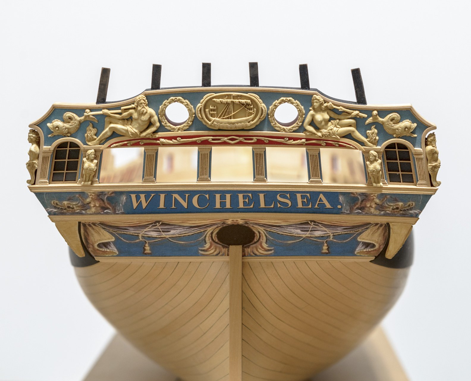
I have finally finished the transom detail. For this kind of work I clamped the hull to the work table with the transom face up above table height. I used the same background paper below the windows as I did above. When fitting the figures that cover areas of molding I decided to notch the figures and leave the molding untouched. Seemed far easier to replace the figures rather than fix misplaced gouges, etc., in the molding. When painting the figures, I lightly rubbed my finger over the high and low areas to achieve a variation in the color depth of the paint. This, along with rounding the back portion of the figures slightly, gives the figures a three dimensional look. Unfortunately, the lighting in the photo makes if difficult to see this. Mike

- 607 replies
-
- 26
-
-
- winchelsea
- Syren Ship Model Company
- (and 1 more)