HOLIDAY DONATION DRIVE - SUPPORT MSW - DO YOUR PART TO KEEP THIS GREAT FORUM GOING! (Only 75 donations so far out of 49,000 members - C'mon guys!)
×


Stuntflyer
-
Posts
1,197 -
Joined
-
Last visited
Content Type
Profiles
Forums
Gallery
Events
Everything posted by Stuntflyer
-
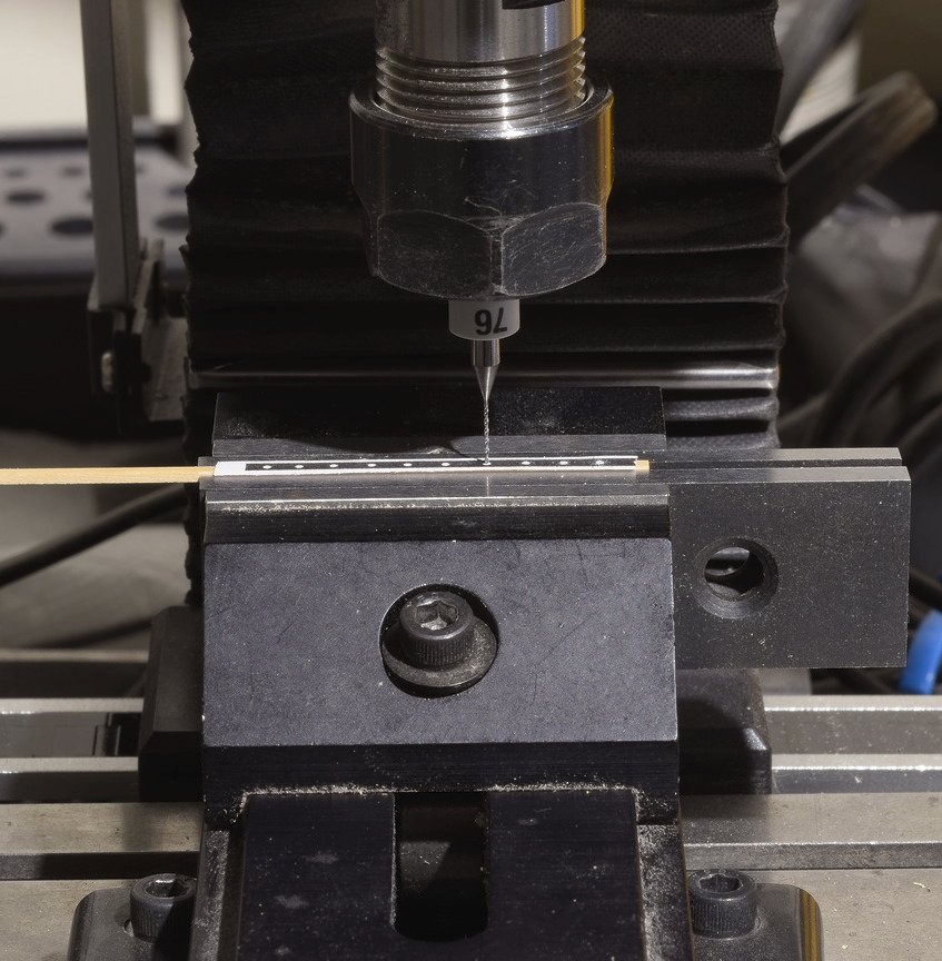
 After adding the two ring bolts to the rudders spectacle plate, I moved onto the the gudgeons and straps. These were made in the same way as I did for the rudder. The mill comes in handy for drilling the strap holes. 7 layers of masking tape give the right thickness to sand the gudgeon and strap down to 1/32" before tapering. The only working hinges are at the top and bottom of the rudder. The other three are faked by gluing the pintles into the gudgeons. Mike
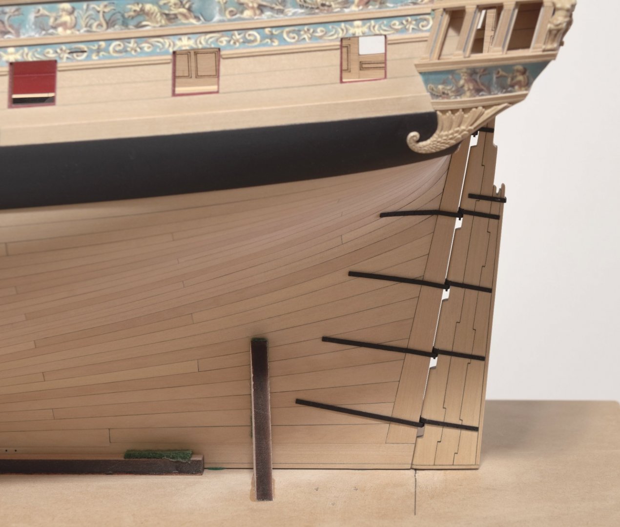
- 607 replies
-
- 29
-

-
- winchelsea
- Syren Ship Model Company
- (and 1 more)
-
Looks really nice, Frank! Mike
-
That looks great, Chuck. I was wondering what that last beam was going to look like. Actually it's much wider than I thought. Will you remove it before you paint the inside of the transom? Mike
- 1,784 replies
-
- 1
-
-
- winchelsea
- Syren Ship Model Company
- (and 1 more)
-
Much to my surprise, Chuck was able to laser cut the rudder from 1/4" boxwood. From what I understand it took some experimentation with the settings in order to achieve a good result. I think that you will agree that he did a great job. The black painted straps were first thinned down to 1/32” and then tapered aft down to 1/64”. The strap bolts were made from 20lb mono and are press fitted deep into the drilled holes, but not bottomed out. No gluing necessary. I added only two hoops at the top of the rudder. These were made from a thick, pliable cardboard type material that I found in a package for a mini miter box. They were wrapped around the rudder in one piece and the ends joined at the leading edge so as not to be seen. The uppermost hoop was omitted as it will be hidden by the rudder trunk. I used a .010 brass strip to help in getting the bolts to stand proud consistently. I drilled an oversize hole in the strip. The hole was placed over the mono and then the mono was flush cut. Before removing the brass strip, I pushed down on the mono with a small dowel to make sure it was flush with the strip. Mike
- 607 replies
-
- 22
-
-
- winchelsea
- Syren Ship Model Company
- (and 1 more)
-
Aha! Do over Mike doesn't feel so bad now. 😆
-
Well, I must say, you certainly have the longboat builds down pat. I've lost count on how many you have completed so far. Nicely done, Thomas! Mike
-
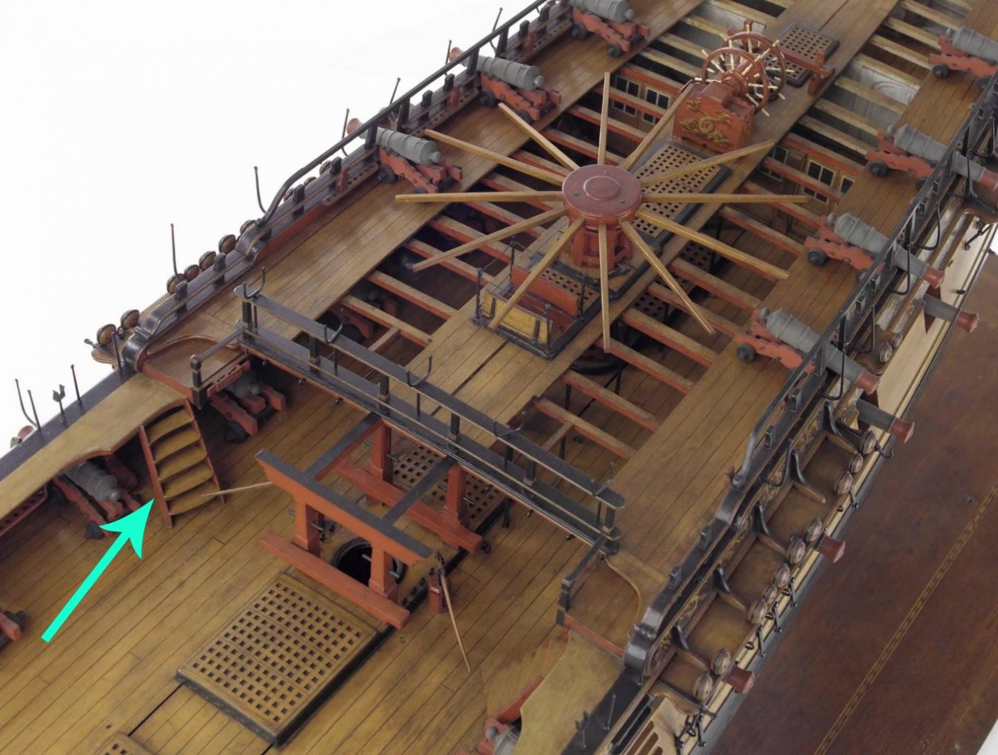
Will the Winnie have a ladder like this one. It looks like it's twisted in order to conform. Mike
- 1,784 replies
-
- 4
-
-
- winchelsea
- Syren Ship Model Company
- (and 1 more)
-
Thanks so much guys for the nice compliments! I wish I could move along a bit faster but, I often find that the hurrier I go, the behinder I get. I guess I'll leave that for the experts. Mike
- 607 replies
-
- 3
-
-
- winchelsea
- Syren Ship Model Company
- (and 1 more)
-
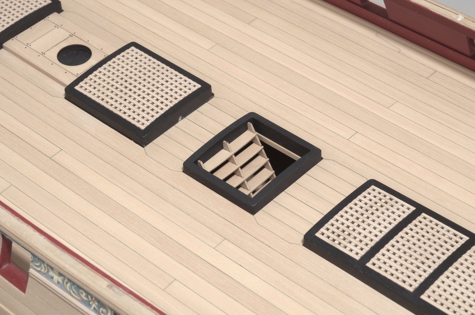
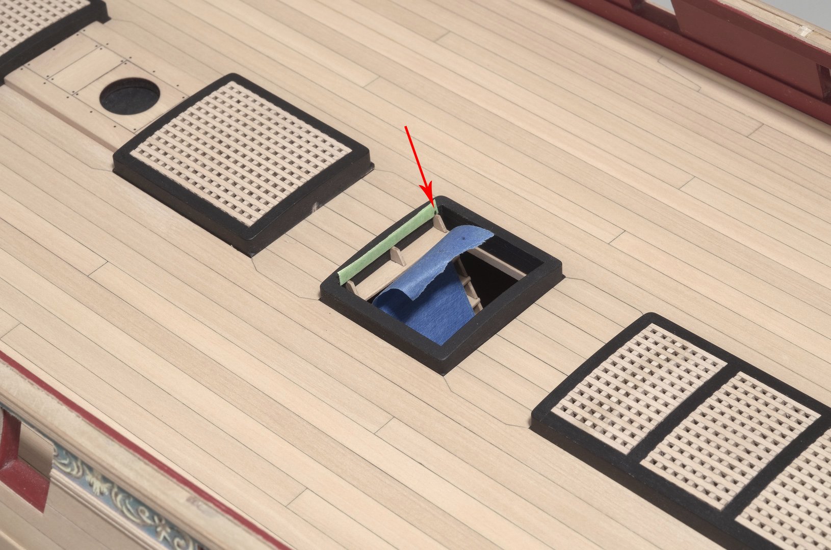
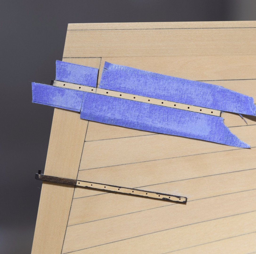
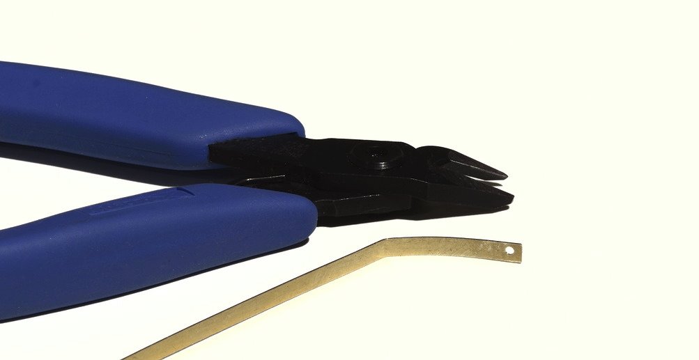
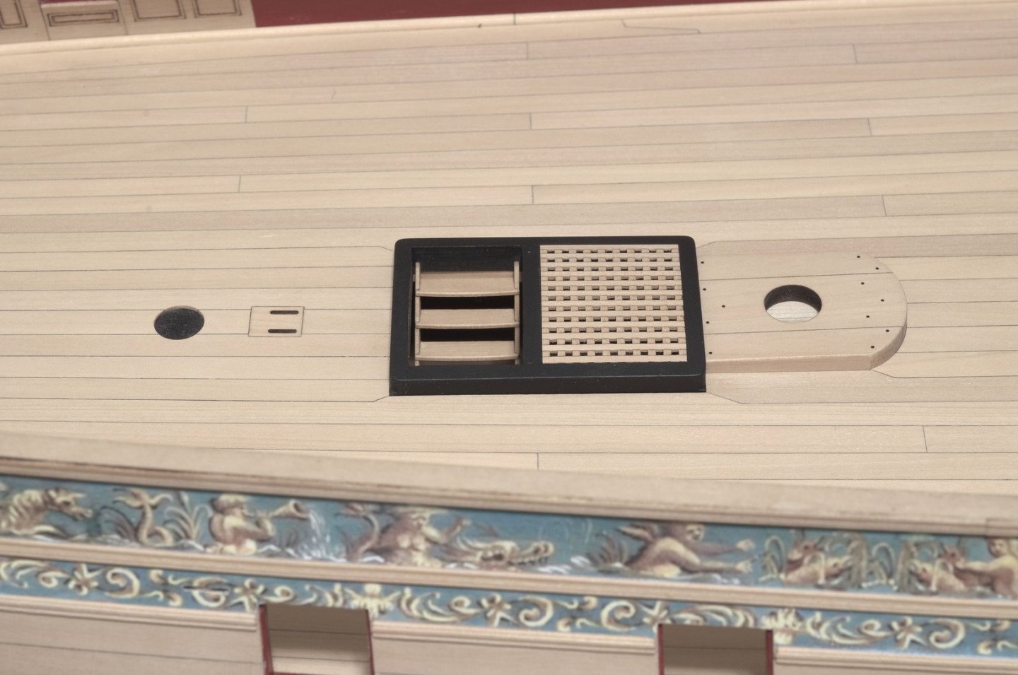
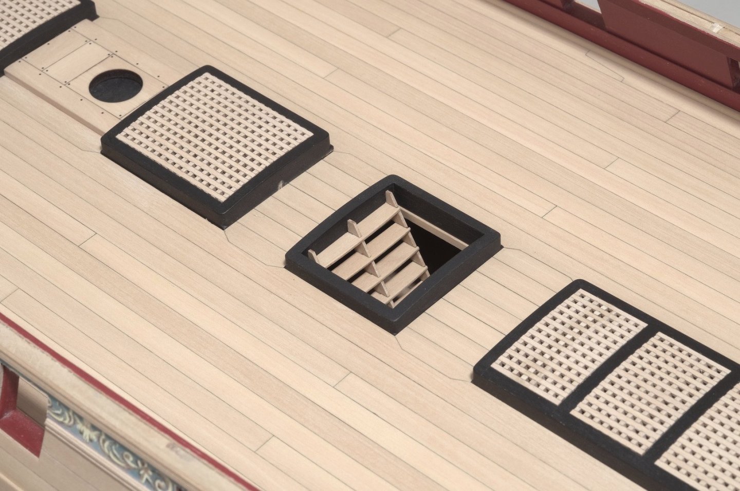
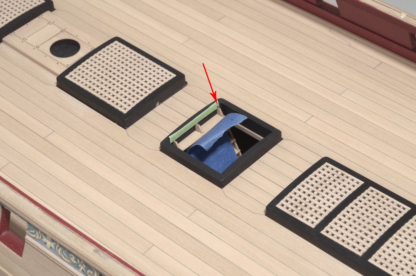
I've been working on a number of things such as the gun port lids, gun carriages, ladders and rudder. Today I finished the two ladders that go below the gun deck. The initial assembly was all about getting things square and locked up, using the two sides and top and bottom steps. Once done, I inserted the remaining steps. Each step needed to be beveled slightly on the bottom in order to fit into the side grooves. To keep things neat, I glued the steps to the sides from underneath the ladder with a tiny drop of slow drying 3 hour epoxy. The epoxy will eventually wick into the joint and not be seen when the ladder is installed. Once dry, I rounded off the top forward edge of each step and sanded the step overhangs flush with the sides of the ladder. After a coat of W-O-P the ladders were ready to install. The ladders position was established in such a way that the back and bottom of the sides are sitting flush to the coaming and deck below, respectively. Four layers of the green tape was used to mark the position of the ladders top. The blue tape makes it easy to hold onto the ladder while inserting it. When installing, center the top of the ladder within the coaming and up against the bottom of the green tape. Then lower the bottom of the ladder onto the deck below. Notice where I marked the position of the ladder on the green tape. Mike
- 607 replies
-
- 31
-
-
- winchelsea
- Syren Ship Model Company
- (and 1 more)
-
Chuck, I must have read this a half dozen times and yet I'm still not clear on what you are saying. Thanks, Mike
- 1,784 replies
-
- 1
-
-
- winchelsea
- Syren Ship Model Company
- (and 1 more)
-
By "level" do you mean parallel to the bottom of the keel? I checked the plan drawing and the aft port hinge tops for each lid measure that way. The exception being the port at the bow.
- 1,784 replies
-
- 1
-
-
- winchelsea
- Syren Ship Model Company
- (and 1 more)
-
Chuck, I have a question regarding the positioning of the tops of the gun port lid hinges. How is the position for the top of each lid hinge determined? Mike
- 1,784 replies
-
- 1
-
-
- winchelsea
- Syren Ship Model Company
- (and 1 more)
-
Yes, use 3/16"
-
Thank you all for the comments and "Likes". Matt>I've been using a #2b pencil on one of the two plank edges being joined in order to simulate hull and deck caulking. If I wanted a darker simulation I would pencil both plank edges. Chuck provides a color pdf of the friezes that can be printed on regular paper stock. Mike
- 607 replies
-
- 3
-
-
- winchelsea
- Syren Ship Model Company
- (and 1 more)
-
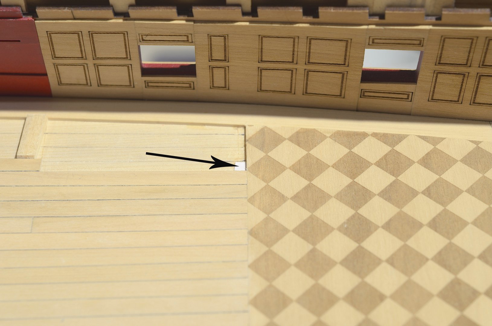
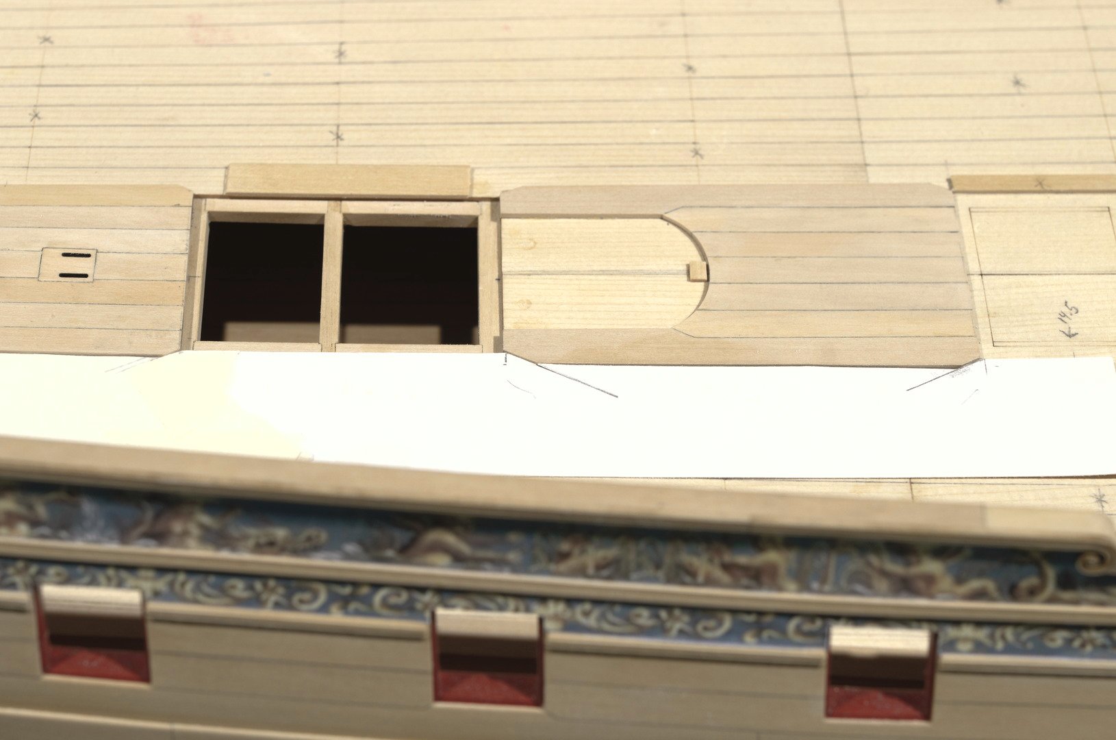
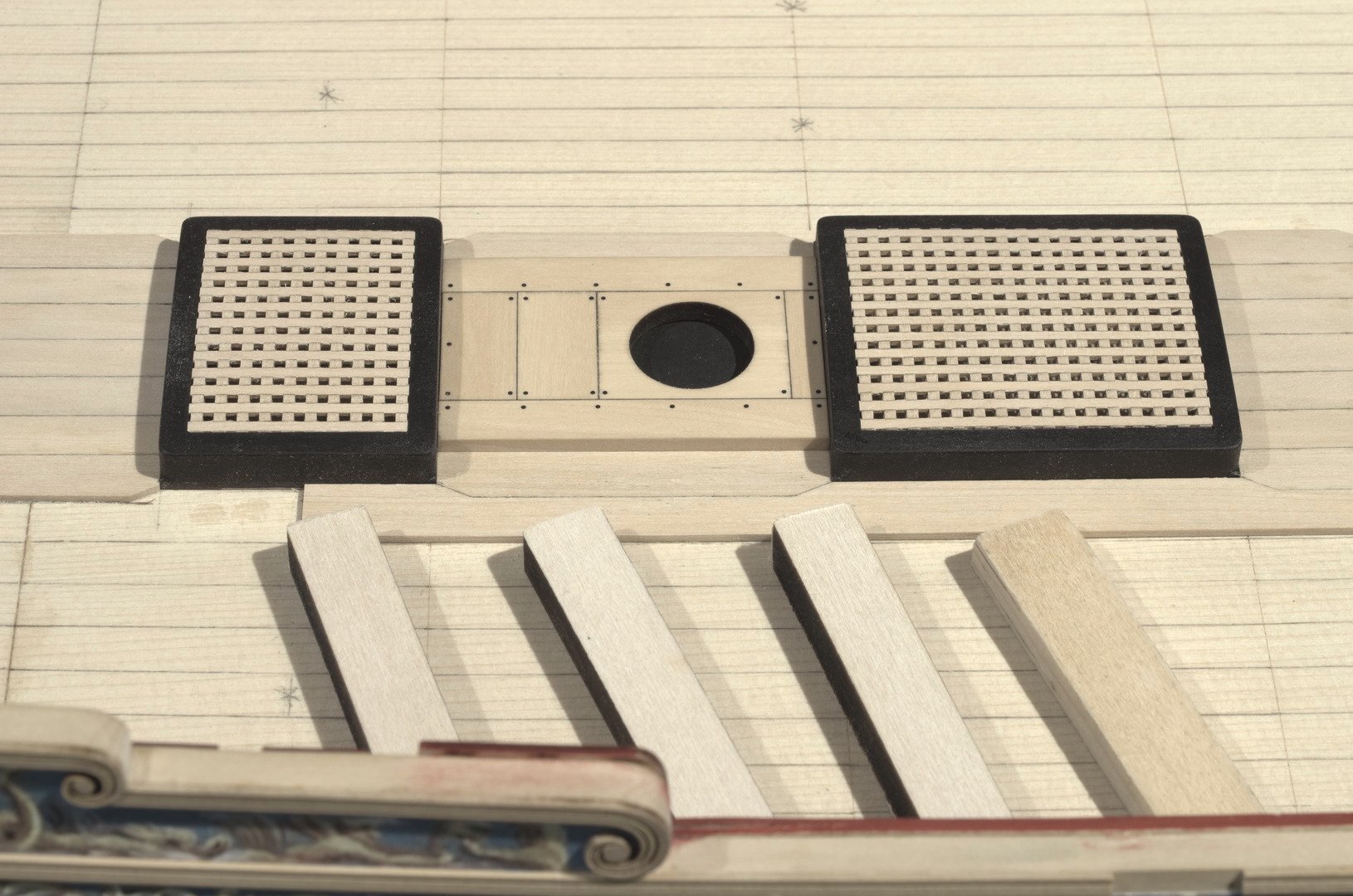
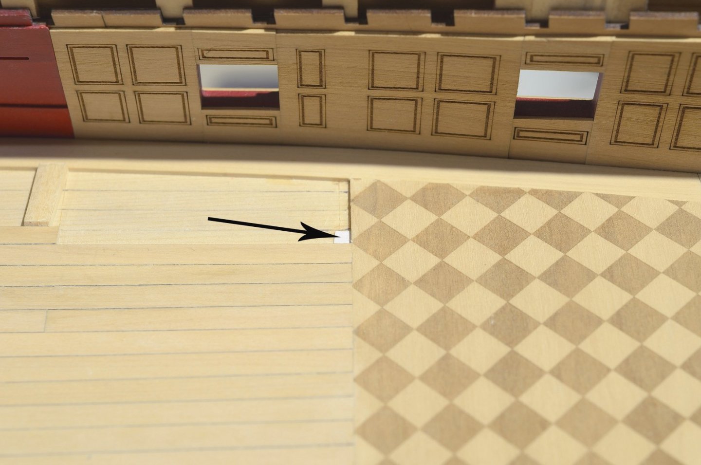
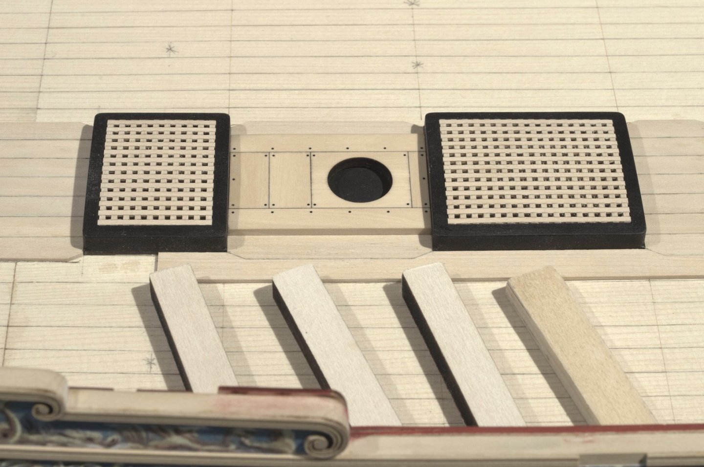
The deck planking and waterway are finished along with a coat of W-O-P. I found a height discrepancy, so I added a paper or card stock shim to compensate. The idea was to avoid having to sand the parquet floor in order to even things out. Mike

- 607 replies
-
- 32
-
-
- winchelsea
- Syren Ship Model Company
- (and 1 more)
-
Nice joinery on the knee, Christian. Not that you would need to do this with Chuck's laser cut parts, but. . .To get a 90° edge I usually sand the adhered sandpaper flush with the edge of the block. I will then raise the part off the table slightly with a thin sheet of wood so the sandpaper touches the entire edge of the part being sanded. Mike
-
Matthias, Your model is looking really nice! Just a reminder to end the plank here. Same idea for the one at the QD. Mike
-
Tom, I know how difficult back issues can be, so I hope that you get better very soon. My two cents is this. .My boxwood built Winnie with 90% of the deck planking completed weighs a very manageable 5 lbs. Go with Alaskan yellow cedar or boxwood (if you have it). Purchase everything available for the build from Chuck. That includes the bulkheads. Make things easier on yourself, not harder. We all look forward to seeing the project as it progresses. Mike
-
I used an angle of 27°, Ken. Just an arbitrary number I came up with after looking at the plan.
- 607 replies
-
- 1
-
-
- winchelsea
- Syren Ship Model Company
- (and 1 more)
-
Likewise, Mark and I'm not an engineer. Mike
-
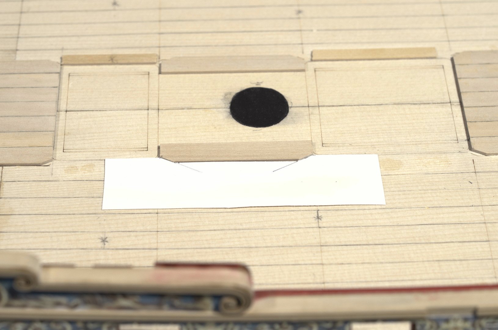
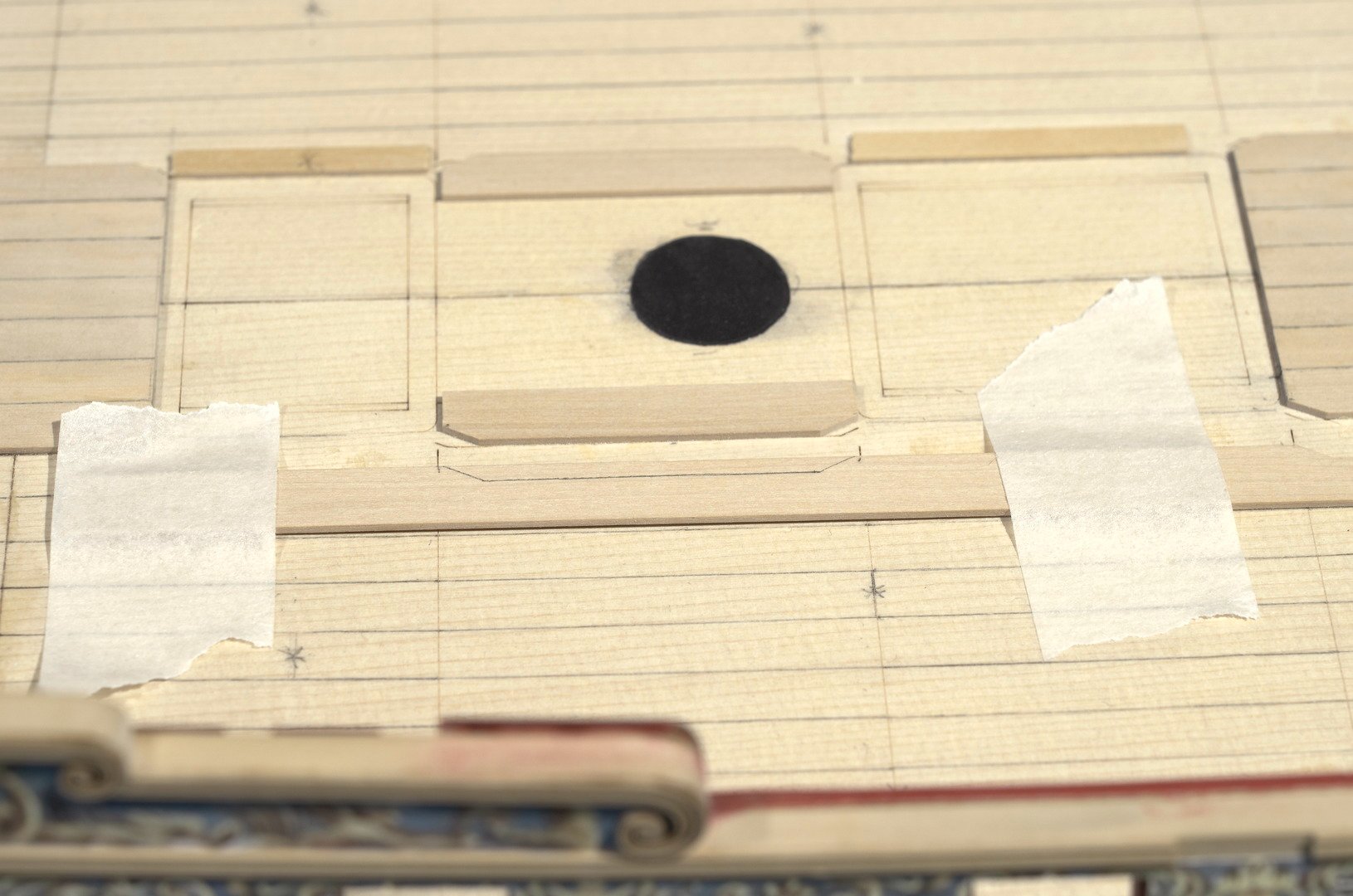
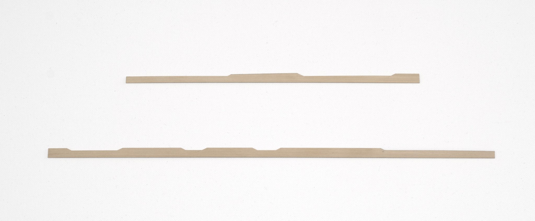
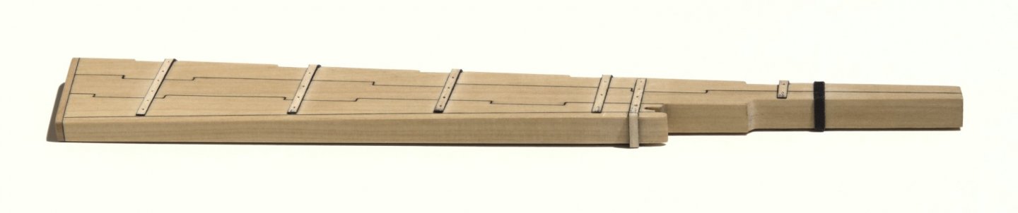
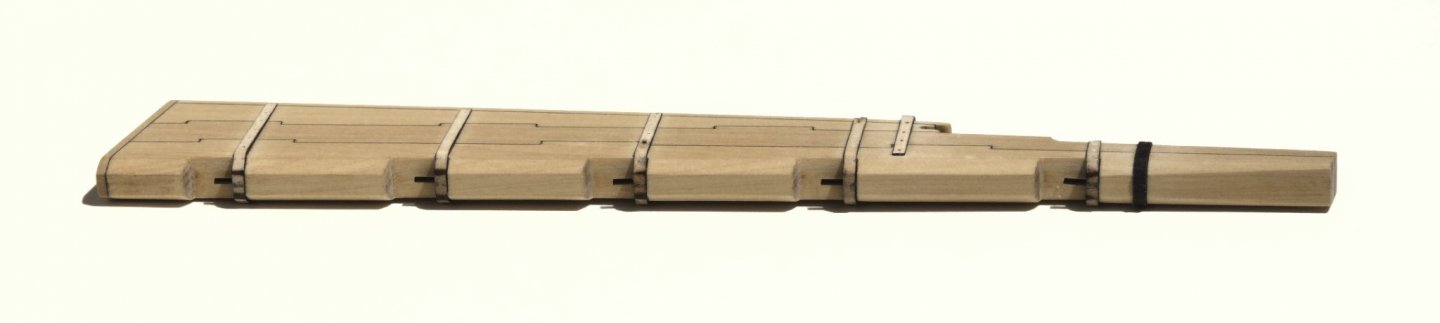
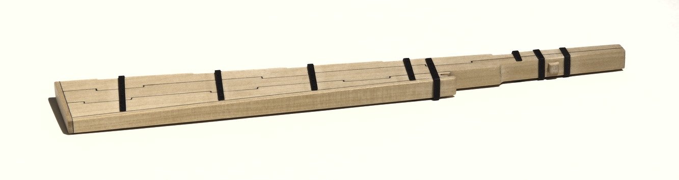
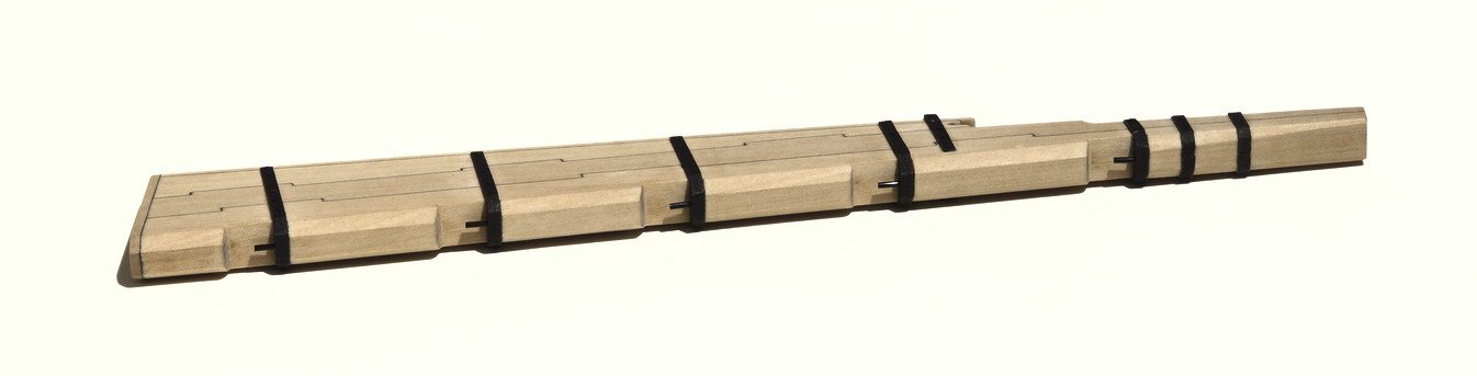
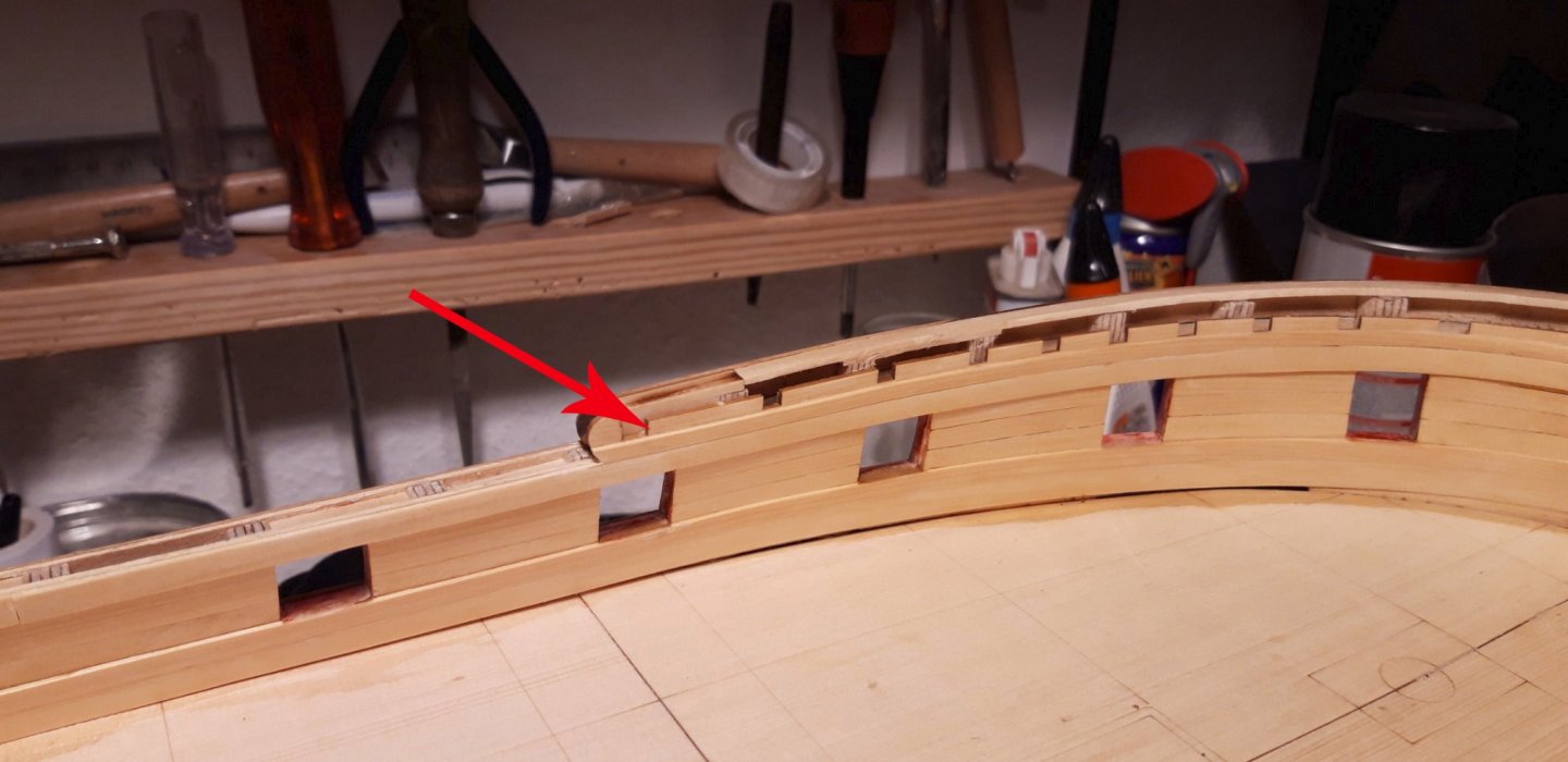
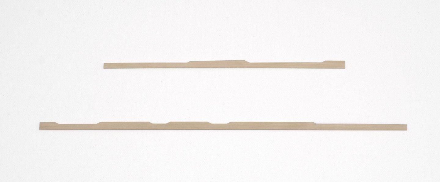
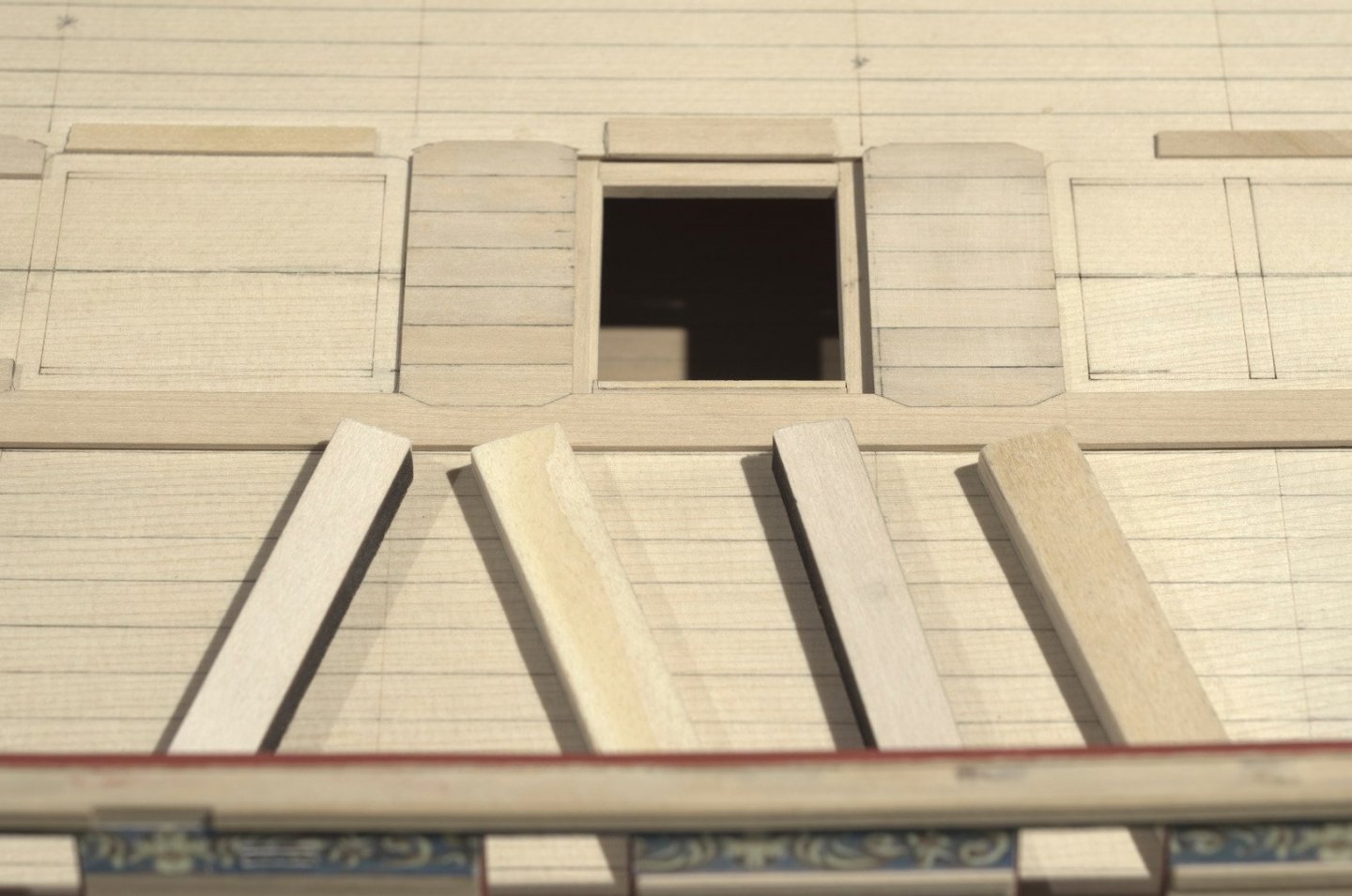
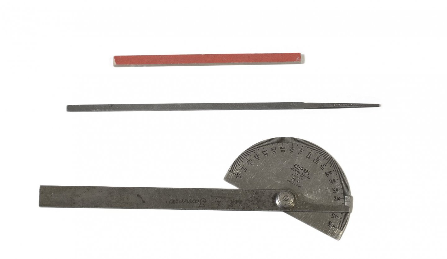
The planks that go around the mast partners and coamings are difficult to make and took some careful planning. In a failed attempt, I tried to make all the cutouts at one time. Rather than waste more wood, I decided to make card stock templates that closely matched the area being worked on. The plan was to work one tab at a time. Once a tab was completed, I would then move onto the next tab. This template was tricky because it required spanning two tabs in order to establish the proper shape. Notice how the tab tapers in width. When it came time to glue, I adhered a short section of the plank to the false deck. This would make it easier to finish up the remaining unglued areas afterwards. Softer wood strips were used as clamps against the margin plank. Once the glue was set, I moved onto gluing the remaining areas of the plank. Pillar files and a sanding stick were used to shape the parts. Sticky back sandpaper was adhered to the stick and sanded flush with its edge. Mike


- 607 replies
-
- 22
-
-
- winchelsea
- Syren Ship Model Company
- (and 1 more)
-
Thank you, Tom! I happy to hear that your health has improved and you are ready to build the Winchelsea. Mike
- 607 replies
-
- 1
-
-
- winchelsea
- Syren Ship Model Company
- (and 1 more)
-
Welcome aboard, Tom. Looks like I'm going to learn a lot of new things from your Winnie build. I'm looking forward to that. Mike