georgeband
-
Posts
307 -
Joined
-
Last visited
Content Type
Profiles
Forums
Gallery
Events
Everything posted by georgeband
-

Whats the best book on rigging for a beginner?
georgeband replied to Stuka's topic in Masting, rigging and sails
I bought a copy of Ashley's Book of Knots and really enjoy it, but it's not a beginner's book for modelling. Prices vary widely so look around before you buy. The Young Officer's Sheet Anchor by Darcy Lever is one that I recommend especially if you combine it with internet searches for specific knots and details. Facsimile copies of the 1800ish book are readily available or you can splash out on an original copy. It's a great introduction to knots and rigging and masts and sailing, and to the language of the time. It's inspirational and it pulled me into the world of ship modelling. George -
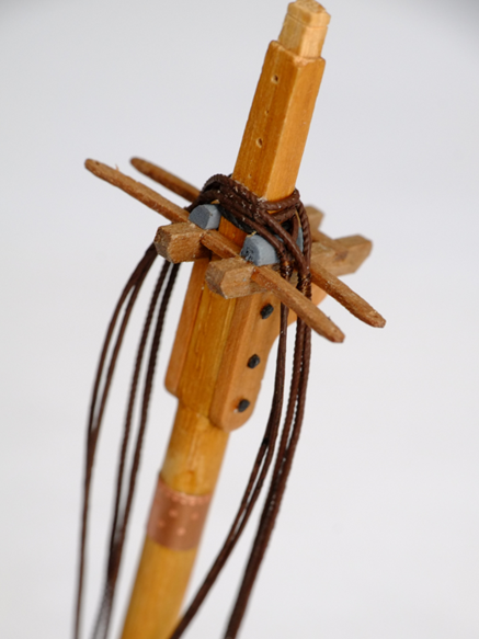
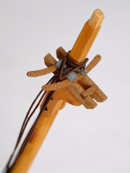
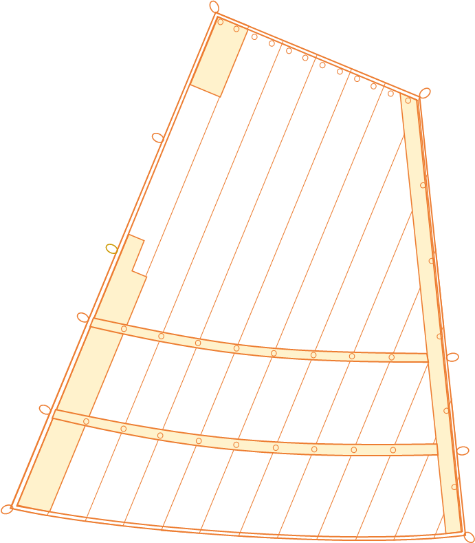
Shrouds fitted to fore mast The mispositioned shrouds came off the masthead with no problems at all and I re-used them starting from the aft end of the foremast. The first pair is a pendant and one shroud, both fully served by painting the linen thread, set to aft and starboard. Then follows a similar pair to port, then two forward pairs of shrouds to starboard then port. The final pairs use Ropes of Scale 0.6mm thread with the middle section painted to represent serving. The lay of the thread shows through the paint and I might give it a few more coats or learn to live with it. The pictures show the masthead from aft and starboard The holes in the back of the masthead were predrilled to take three eyes for blocks; the lowest of these is now covered by shroud ropes and I will probably put a new one between the two existing, exposed holes. So much for planning ahead and preparation. Sails Currently I have been drawing sails which is an iterative process with the yards from which they hang. The lengths of the yards are based on drawings for another schooner, but a sail is an integer number of cloths wide, and the distance from the top corners of the sail to the cleats at the end of the yard depends on which sail it is and the notes provided by Steel. So I start with a yard of nominal length and see what width of sail fits it best, then adjust the yard so that the sail sits properly on it. It gets more complicated for a gaff sail where the runs of cloth are not necessarily perpendicular to the yard and you can also adjust the angle of the gaff. Computers do make this step easier and I use Powerpoint simply because I am familiar with it from work. (Work is no longer a distraction for me 😁.) I know that there are better drawing packages available but I would have to climb another learning curve to use them. One other change I have to make to 'finished' tasks is about the number of hoops on a mast for a gaff sail. I had allowed for two hoops to each cloth in the sail which gives about a dozen for the fore and main gaff sails. Steel in his drawings of gaff sails shows one hoop per cloth so my preloaded mast has far too many hoops on it. They are easily removed with a snip and this is much easier than trying to fit more hoops on at this stage. The pictures below are the fore gaff sail and the completed lower section of the fore mast George

-
Thank you Trevor and Henry for your suggestions. I do like the idea of moving a sheet and tack from their cringles on the (short) sail to the cringles on the lower corners of the bonnet. Toggles would make it a quicker procedure. Darcy Lever discusses toggles on page 115 of The Young Sea Officer's Sheet Anchor and there are small illustrations on other pages too. He says that a cringle on the sail is made just large enough to pass the eye on the end of a rope through it. The toggle is then put through the eye. (My childhood experience with duffel coats was that the toggle was tied into the end of the rope. To use it the toggle was passed through the equivalent of a cringle and then turned 90 degrees to lock it. Obviously it did not follow naval practice from 200 years earlier.) As a further complication on a schooner, and probably a ship, a stay sail or jib had two sheets on it so that the windward one was slack and ready to be used after tacking. The 'eye at the end of the sheet' becomes an eye at the end of two sheets for the toggle to be inserted. I will be delighted if anyone has information on this detail but will make something reasonable if nothing surfaces. At 1/64 scale the fine structures of splicing and seizing soon disappear. George
-
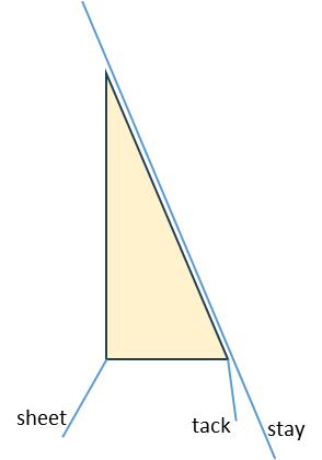
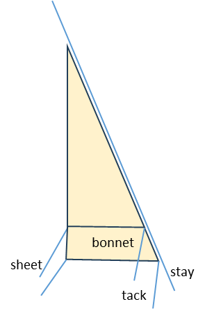
A bonnet was an extension that was attached to the bottom edge of a sail to increase the area; a reef could only make the area smaller. Steel gives good descriptions of how they were made and how they were attached. This is enough information for me to make a stay sail with an attached bonnet, and I know from a sub-Lieutenant's log book that this was done on HMS Whiting. What I do not know is what happens with the sheet and tack at the bottom of the sail. The stay sail would have its original sheet and tack when it is without a bonnet. When the bonnet is attached it will also need a sheet and a tack otherwise it becomes a curtain that flaps in the breeze. Do both sheets belay to the same point, and similarly do both tacks belay to one point? Or do they belay to different points? Or do the original sheet and tack become redundant and are coiled and hung somewhere out of the way? Steel is silent on this topic unless I have missed it. Any assistance will be gratefully received. George


-
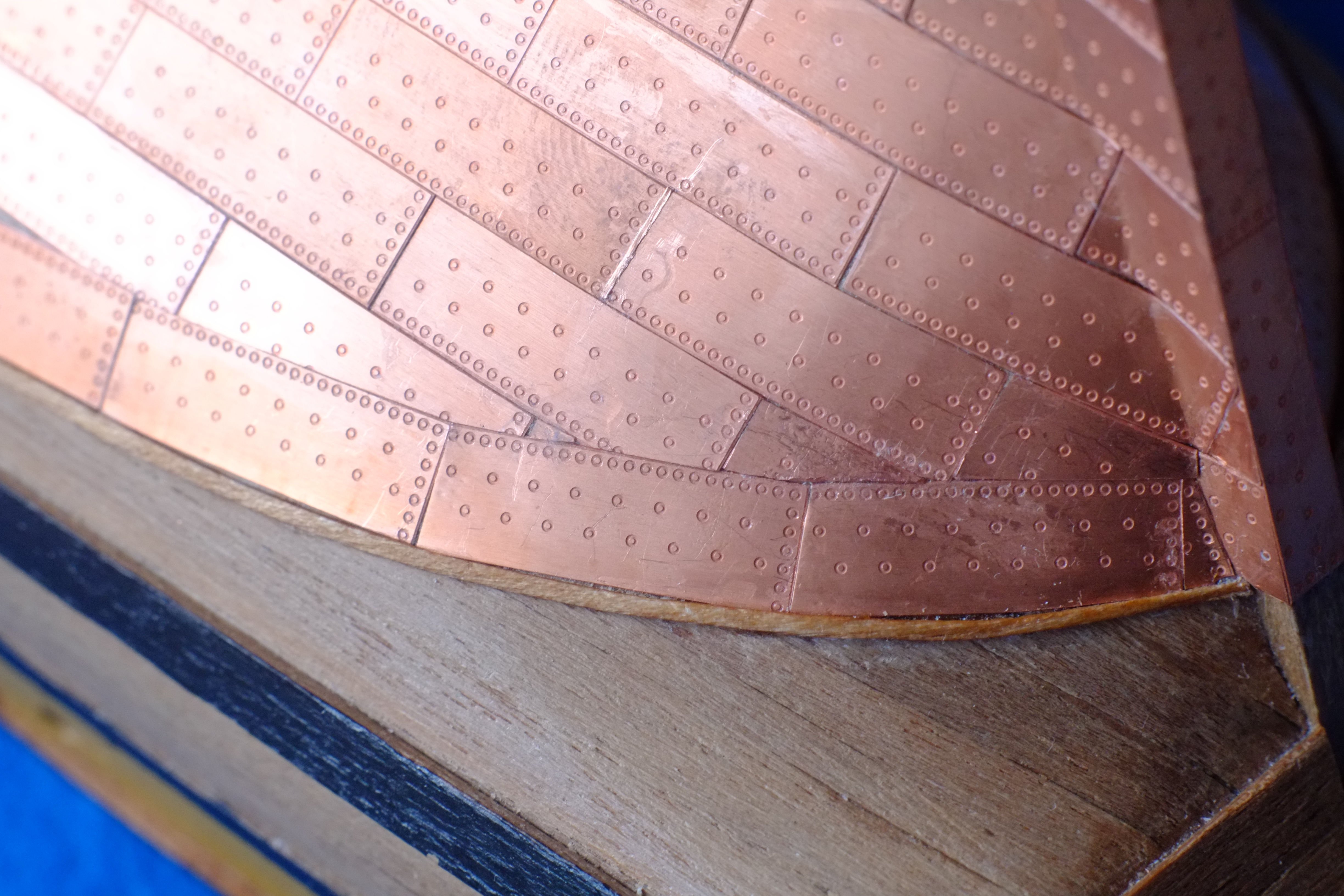
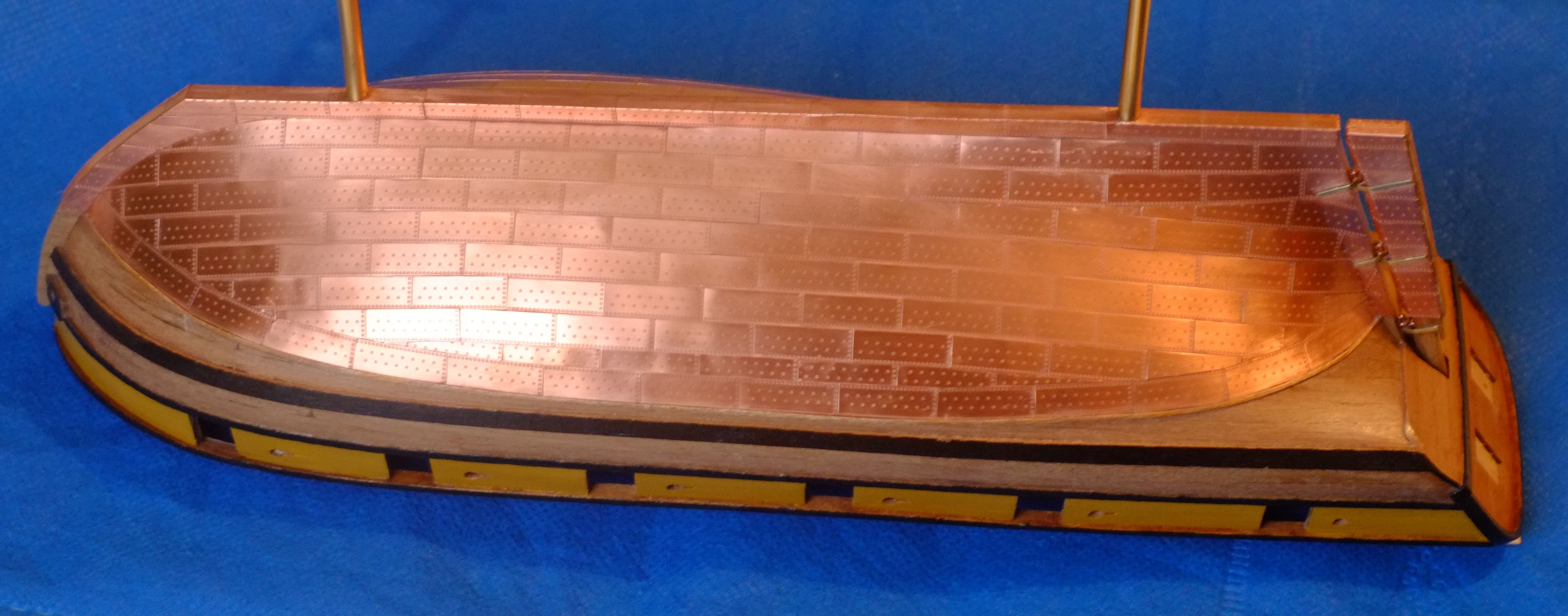
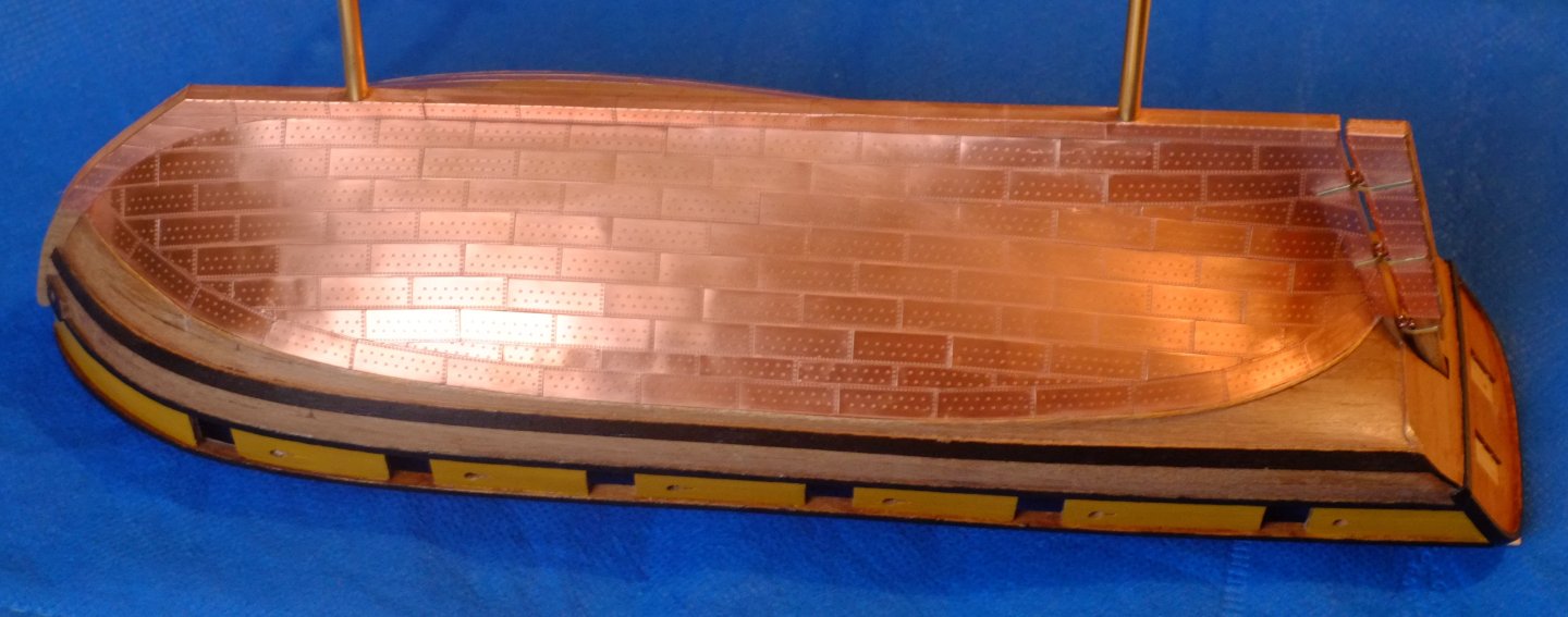
I plated my 1/64 model of HMS Whiting (Caldercraft Ballahou schooner) with Amati plates and it took me about 100 hours to finish the job. Apart from being a slow worker I trimmed the plates so that they did not overlap and betray the overscale thickness. It's a slow process. The picture below shows part of the stern, and a fingerprint to prove that I did it. There are a few narrow gaps between some plates but they are not visible at normal viewing distances. I used grade 0000 steel wool to clean the surface. It caught in a couple of places where a corner of a plate was slightly proud so remedial work with superglue was needed. I wanted to keep the copper shiny. Partly this is personal preference because I want to reflect lighting in the display case when it is finished. The other reason is that the copper remains shiny under the water; the brown or green patina requires air for it to develop. I chose Renaissance wax as mentioned above by RossR and applied it with a miniaturised version of the technique shown in the film Karate Kid - wax on, wax off. A couple of years later the copper is still bright. George

- 20 replies
-
- 4
-

-
- Indefatigable
- copper plates
- (and 1 more)
-
I have browsed through a downloaded copy of Steel's Masting and Rigging, 1794 edition, and he does provide corroboration for Marquardt. There is nothing specific for schooners but I looked at the main (aft) mast of a brig and the only mast of a cutter which have similar layouts to a schooner mast: gaff sail and no square sail. Pages 220 and 222 in Steel have the relevant entries and one states ‘The after-main-shroud must be served from the mast-head to the dead-eye, to prevent its being chafed by the main-boom and gaff.’ It seems that the model which Petersson used for his excellent book was not aware of this. I will be making changes to the fore mast when I get back home. In the meantime I have the slowest internet connection which is similar to the pace of life while on holiday. George
-
Tony, Phil, Thanks for your comments and information. It is a puzzle with incomplete evidence for either option. I'm off on holiday for a while (no grandchildren this time) and will ponder the alternatives over a glass of something fizzy. Perhaps someone else will join in with a definitive answer George
-
I think the picture is doing the rounds just now. A friend found it on Facebook and asked me for comments. I was pleased to say that it's a load of balls and can be disqualified for a large number of reasons George
-
Second thoughts about the shrouds Having fitted the shrouds to the mast head of the fore mast I checked my references again and now doubt my interpretation. I followed the drawings in Peterssen (pp 74, 75) with the pendant at the fore end of the group, then a served shroud, then two more shrouds which were only served over the top quarter as for square rigged vessels. Marquardt (pp 171-3) states that the order was reversed on schooners with the pendant set at the aft end of the group and the aft-most shroud fully served. The justification he gives is that the aft shroud would be in contact with the gaff sail and had to be protected from wear. This sounds quite logical to me, especially since a lower square sail was unlikely to be carried below the spread yard. The rake of the mast also makes it less likely for a square sail to touch a shroud on its mast. Option 1. I trust the model that Peterssen has drawn and ignore logical arguments, and leave my model as it is. Option 2. I assume that Peterssen's model does not necessarily represent all schooners or might be mistaken, and the logical arguments put forward by Marquardt prevail. I strip off the shrouds from my model and reposition them. The repair is more irritating than difficult if I follow option 2 and at the moment I am leaning towards that choice. Does anyone have evidence that the shrouds and pendants on a schooner mast were positioned in reverse when compared with a square rigged vessel? George
-
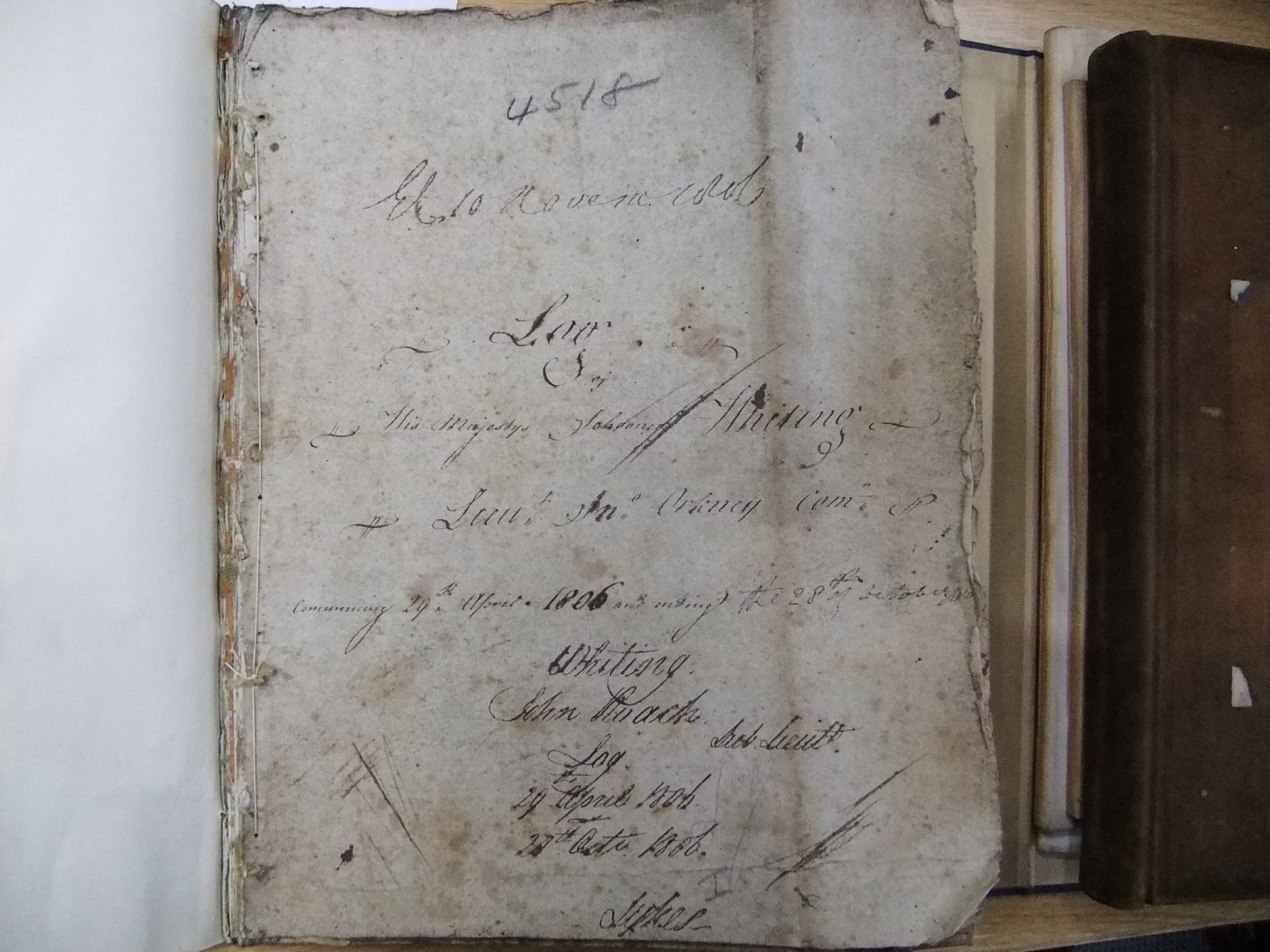
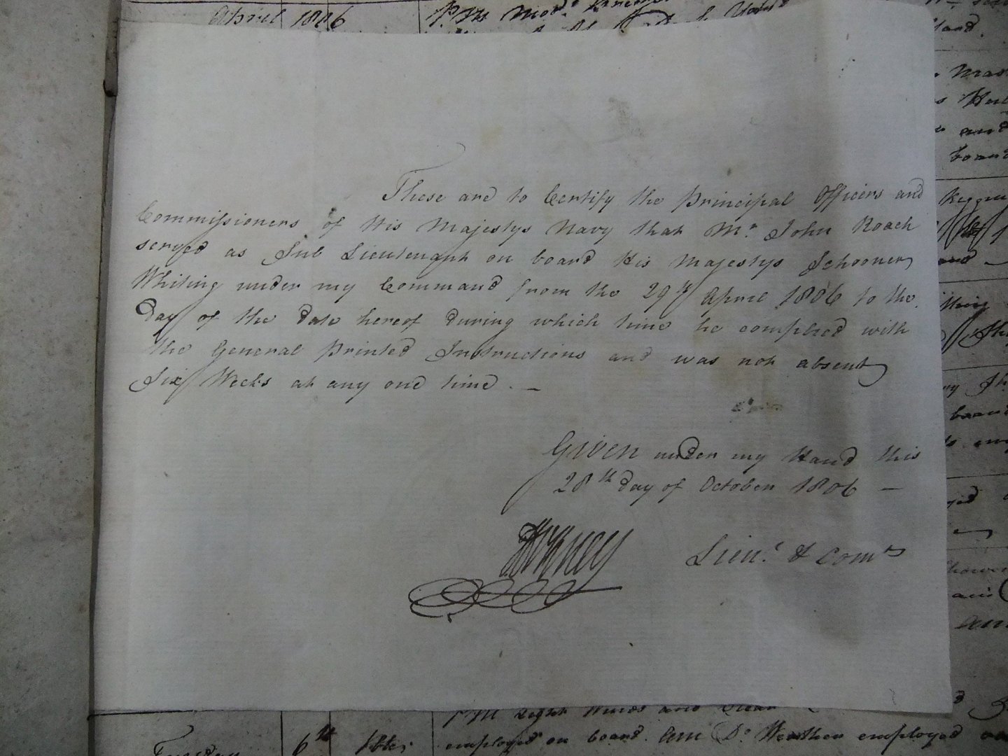
Contemporary documents often copied each other (and still do) so mistakes were repeated and became a truth (and still do). One example that I took a while to get past was the Wikipedia entry for HMS Whiting 1805 which states that at one time Lieutenant George Roach was her commander. Wikipedia gives its references and being a doubting soul I follow them up; the chain ends with Winfield's great history and begins with the Naval Chronicle. The Chronicle got it wrong and the person who should have been named was Sub-lieutenant John Roach. Why am I so confident? Because his log book says so. The commander at the time of Roach's appointment as one of the first sub-lieutenants was Lt John Orkney. There was a George Roach who was in command of a force of Fencibles at the time. Lloyds register in my experience is another reputable source which copied news articles without fact checking them. George
-
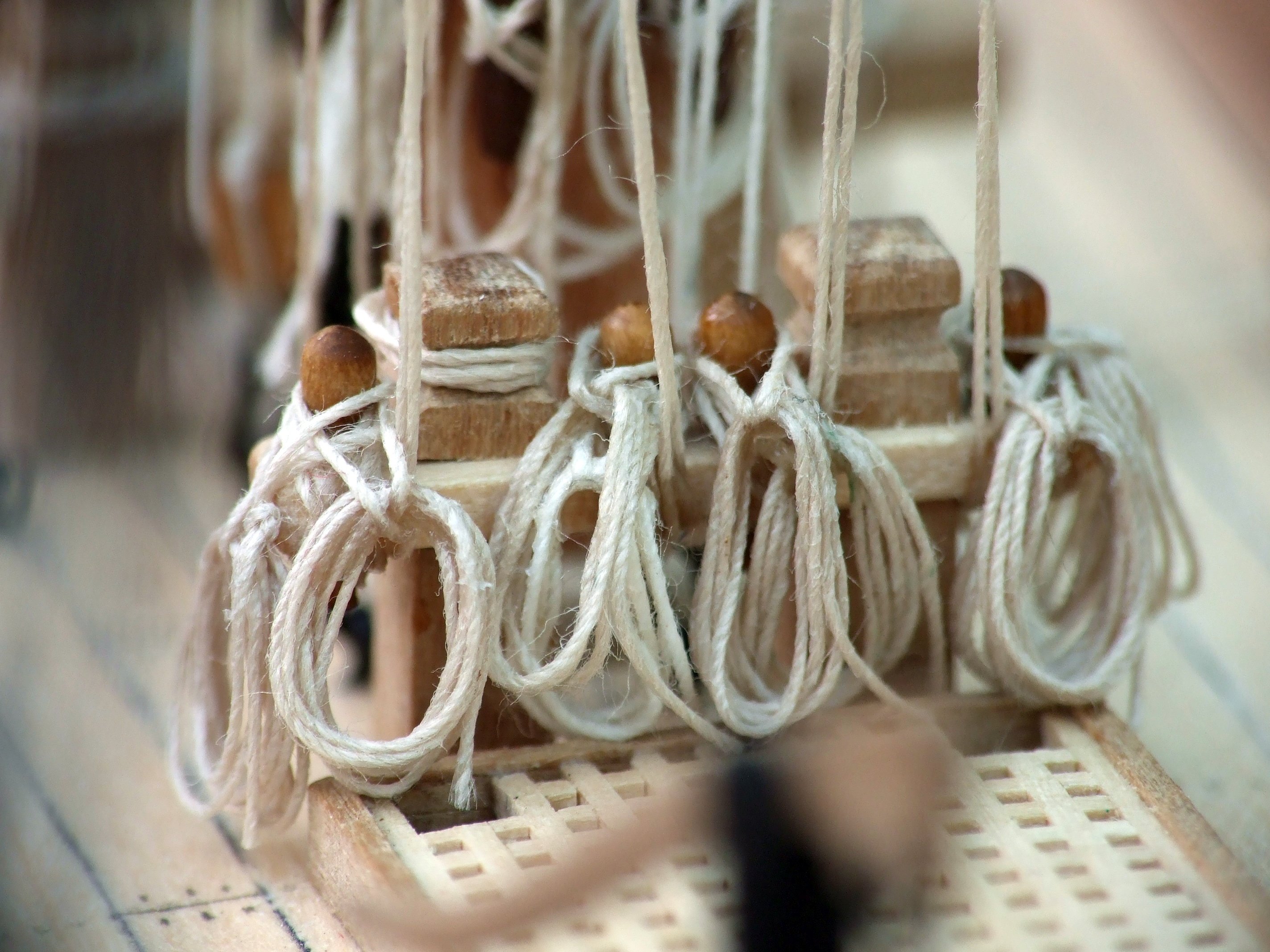
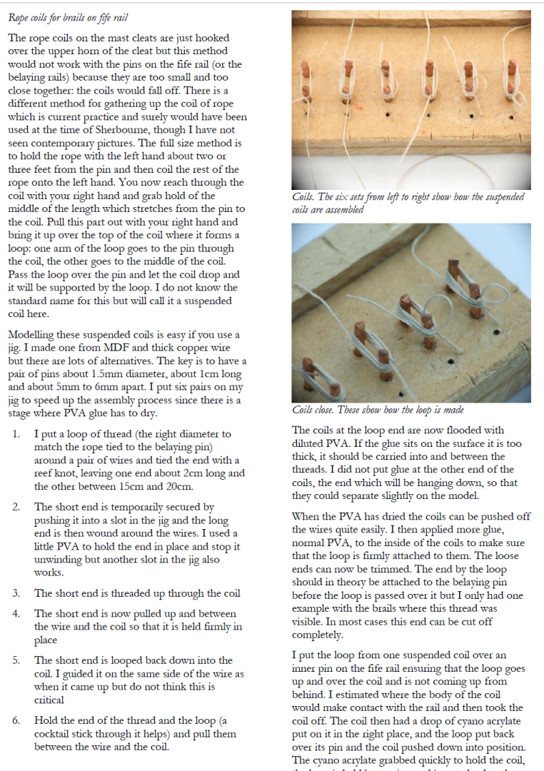
Phil, I used a very similar technique a few years back on my Sherbourne. The difference was in forming the little loop early on in the process. Part of the answer is to make the loop come up over the coils from deep down below and then hook it over a belaying pin. The picture below is page 93 from my book on Sherbourne. Here are the finished coils on the fife rail. The one on the left has a long loop, and the belaying pins are bulky clubs from Caldercraft which I did not replace. The ropes (Caldercraft) are quite hairy at this magnification. George

-
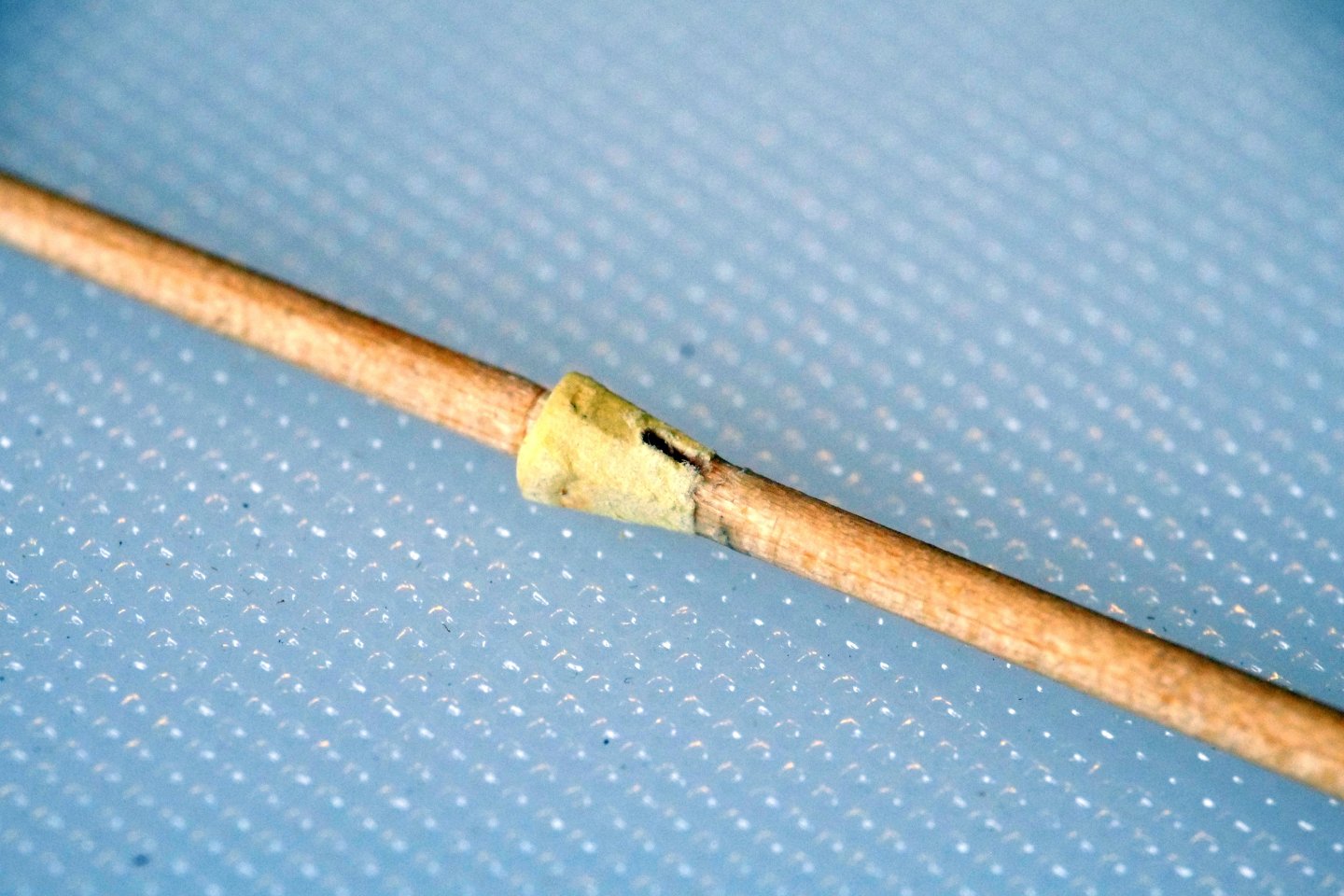
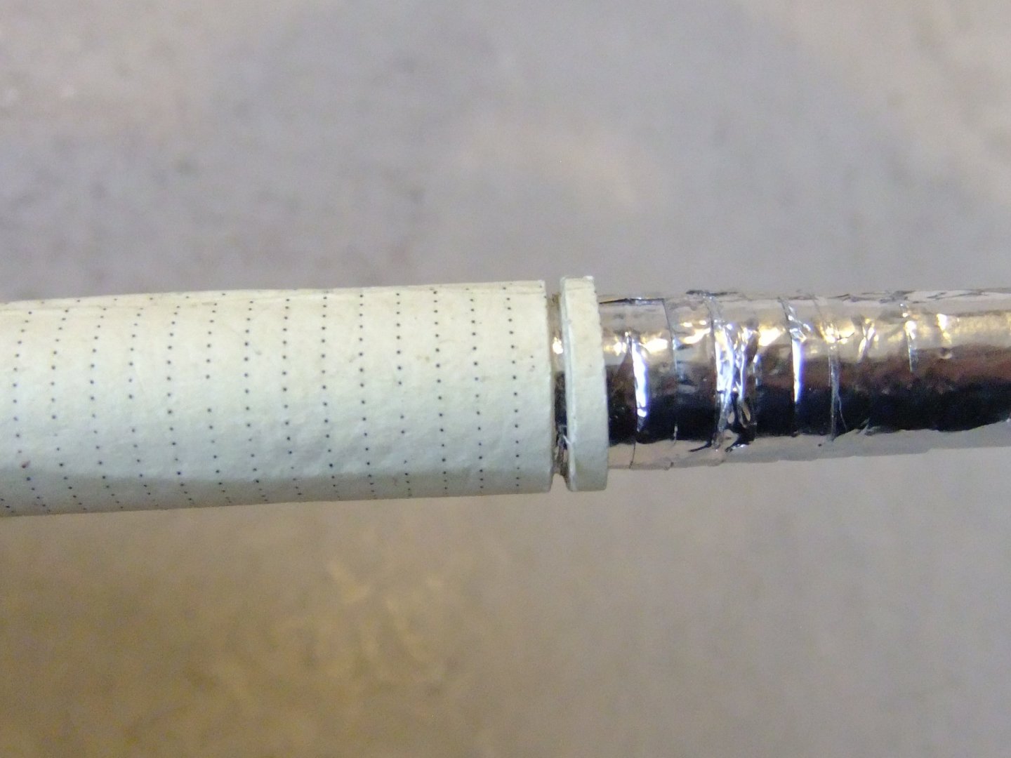
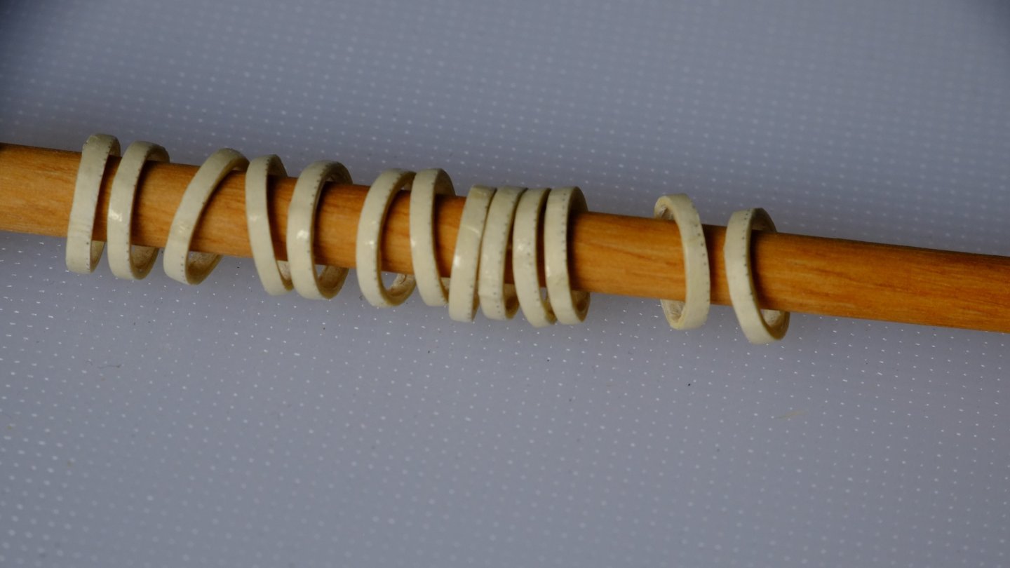
Tony, Phil, Thank you for your comments and the tutorial on sizing photos. I had spent a long time searching for menu options and right clicks to do this, and now have also found that CTRL with a right click opens up a new world for me. Here are a couple of pictures of the topmast to show what can be done with laminated paper. The first shows the heel which has a square section, 4mm to a side, which I built up on a 4mm diameter dowel and then carved back. The second shows a hound of a different colour that sits halfway up the mast and is the locator for a lot of ropes. The sheave for the topsail halyard is drilled through its base. The mast truck at the tip of the mast is another paper winding (not shown here). One piece of advice for this technique is to use plenty of PVA and let it soak into the windings otherwise they can start splitting off. I had a couple of casualties with the heel of the topmast but they were easily fixed. Here are the hoops for the gaff sail waiting to be sliced off - just cut along the dotted line. George
-
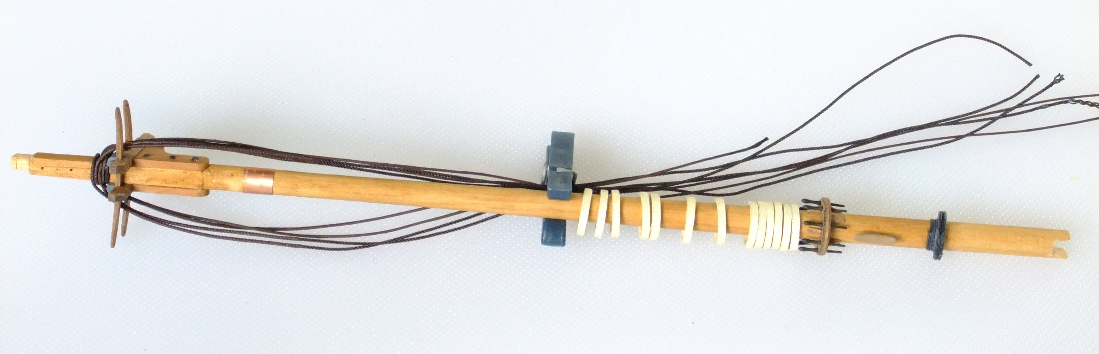
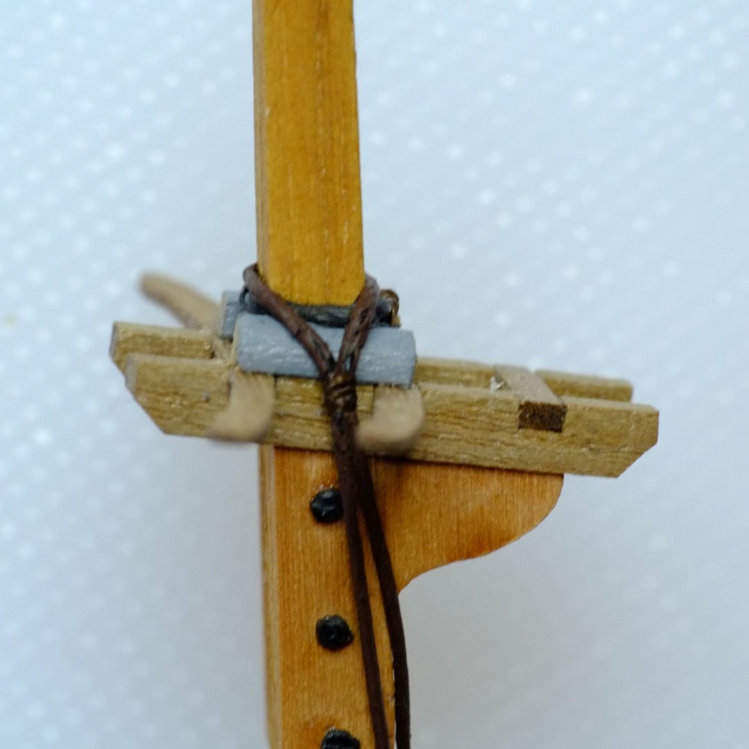
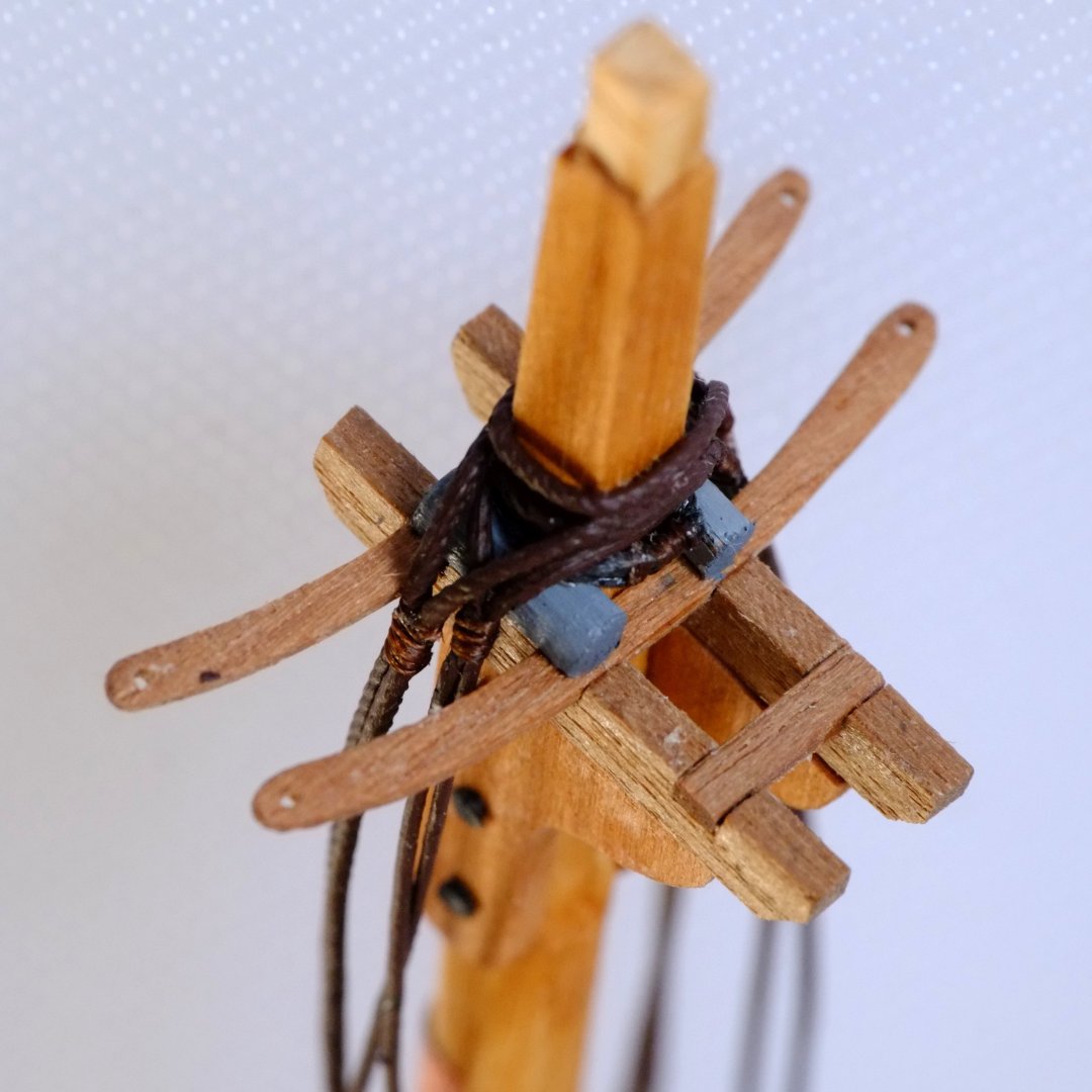
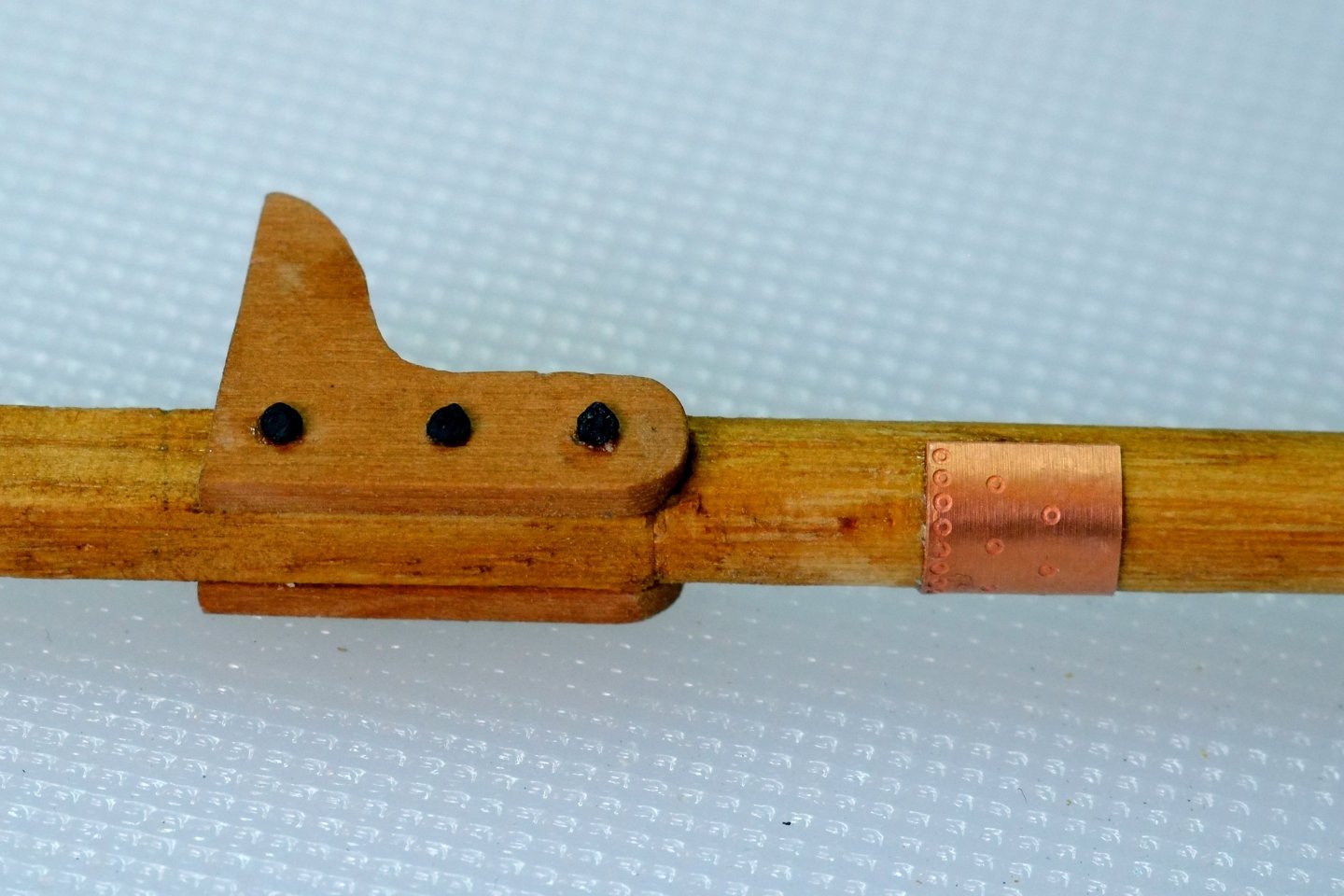
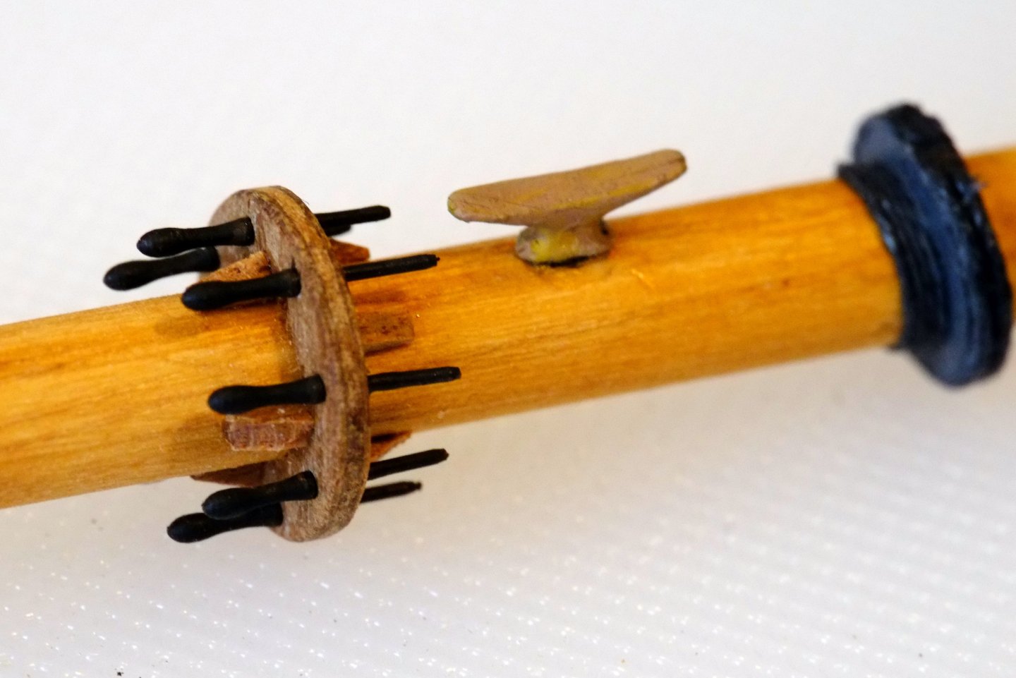
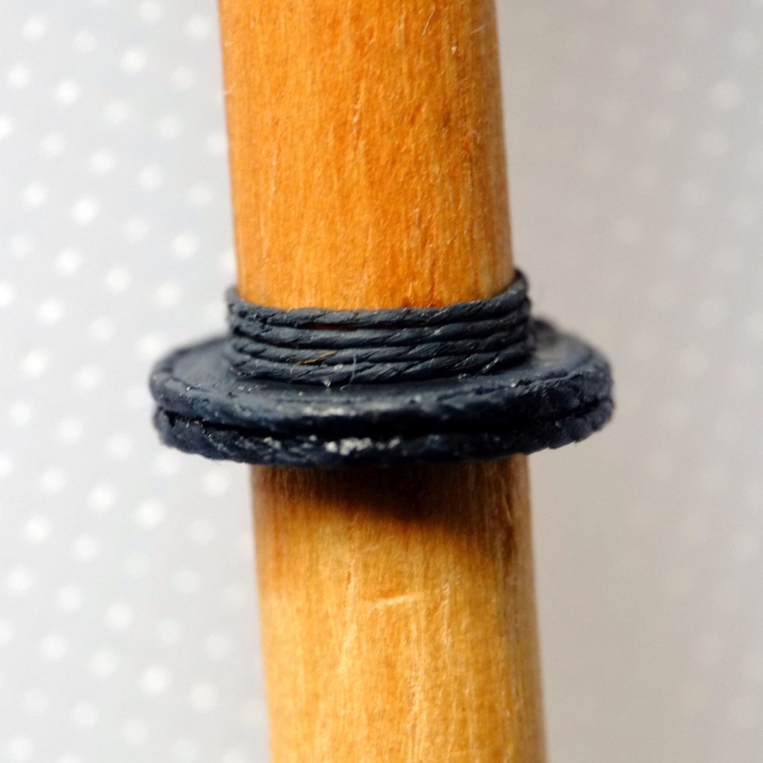
Foremast under construction I have been whittling away making lots of bits for the fore mast and have mostly completed the lower section now. The topmast 'stick' is ready to be attached and rigged but that will be a job for next month. This is the lower section. From left to right we have Step for the mast cap Masthead with shrouds looped over Trestle trees and cross trees Cheeks (hounds) Copper plate for gaff jaws Mini clothes peg to hold the shrouds Hoops for gaff sail Pin rail and belaying pins Single cleat Waterproofing ring over the partners The photos below show some of the details. I have not found out how to reduce their size so please forgive the messy look in places from the magnification. The cheeks (or hounds if you prefer) have simulated bolts on the sides. I finally have found a use for the little brass nails in the Caldercraft kits! The copper plate is half of a plate I used for the hull (Amati) and I imagine that a coppersmith would have used the same thing. John Roach's logbook records visits by a coppersmith. I put bolsters on the trestle trees and a rope grommet over the bolsters and here is the first pair of ropes: the pendant and first shroud seized together. The rope is 0.6mm linen thread that I painted brown to simulate serving and the seizing is 0.15mm fly tying thread. I also realised that the cross trees I had drawn were too long so I reduced them for the model. Four loops go over the masthead and this has to be done before fitting the mast cap and topmast. The second pairs of shrouds are from Ropes of Scale 0.6mm dark thread. The hoops for the sail are from laminated paper. I chose a cream colour which provides some contrast with the mast and suggests new wood. I calculated that I would need 11 for this sail and have fitted 13 just in case. The mast ring with belaying pins was inspired by the schooner in Peterson's book on Rigging Fore and Aft Craft. I added one cleat below it because I needed one more belaying point. The design of the 'partner ring' comes from my imagination as a way to waterproof the gaps between the mast and the partner planks in the deck. I guessed tarred canvas which is held in place by turns of rope. Next jobs on this mast are to drill holes for eyes in the back of the mast head. The ones I had predrilled are too widely separated and the lowest of them is covered by shroud loops. The topmast and mast cap are ready and waiting. George

-
Robin, There is another thread on a very similar topic in the 'masts rigging and sails' section of the forum which you might not have seen. It has comparisons between standard (cheap) blocks, fine wooden blocks, laminated card and 3D printed. The conclusion from my perspective is that 3D printed is the best looking option. Other opinions are available. https://modelshipworld.com/topic/36649-blocks-wood-card-or-3d-resin/#elControls_1046969_menu Regards, George
-
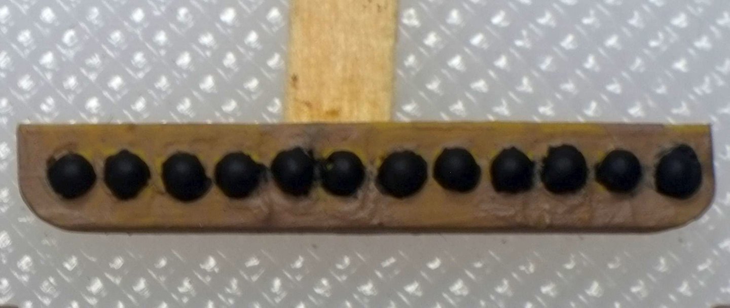
I ran a Google search on HMS Victory shot garlands and found this https://modelshipworld.com/topic/10099-cannon-shot-storage-on-deck/#elControls_300274_menu . This earlier discussion agrees with what Kris and Thukydides say and my own recollections from Victory. Large shot were typically in garlands around hatches. Small shot were typically in long racks between gun ports. Shot were not stacked in pyramids, despite the 'explanation' given for the saying about freezing the balls off a brass monkey. To make a garland I use two strips of plastic card. One has regularly spaced holes, slightly smaller than the shot diameter. The other strip goes underneath and ensures a consistent depth for the holes. For the cannon balls themselves I buy ball bearings from engineering suppliers who sell them by the hundreds or thousands. A chemical blackening solution gives them a rougher texture and a good colour. This whole process becomes tedious so I use one garland as a master and then make resin castings. The smaller balls below are 1.5mm diameter. George

-
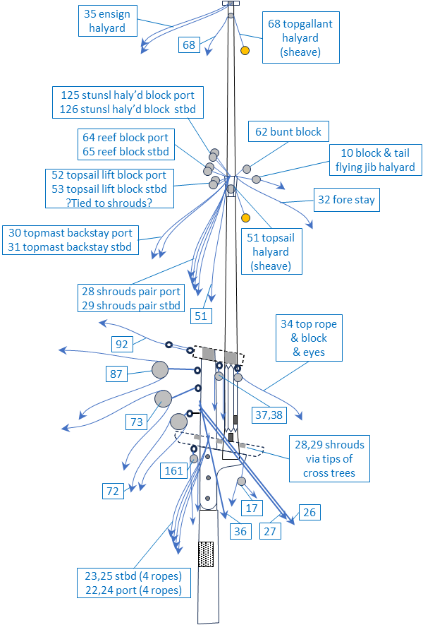
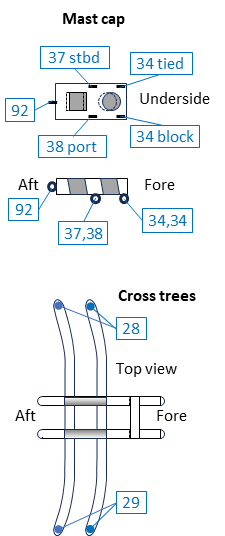
Thank you for your comments, Phil, which provide welcome reassurance that I am not speeding off in the wrong direction. I have now expanded the mast drawings to show the rigging, an activity which again combines research with second-guessing what might have been done 200 years ago. The drawings for the fore mast, below, are supplemented by tables to name the numbered ropes and to show in which order they are placed over the hounds. The fore topmast is crowded with ropes and blocks (15 altogether that rest on the hounds) but they have to go somewhere. The main mast has simpler rigging but still needs decisions about where to place each rope or block. All these drawings and notes will be my guides when I return to model making next year and I fully expect to change my mind about some of the placements. George


-
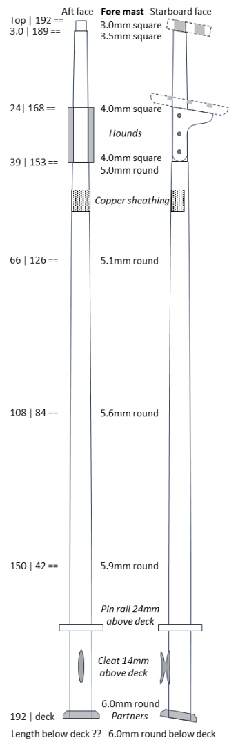
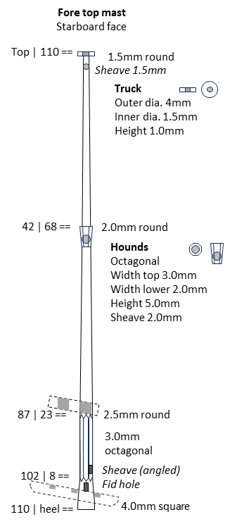
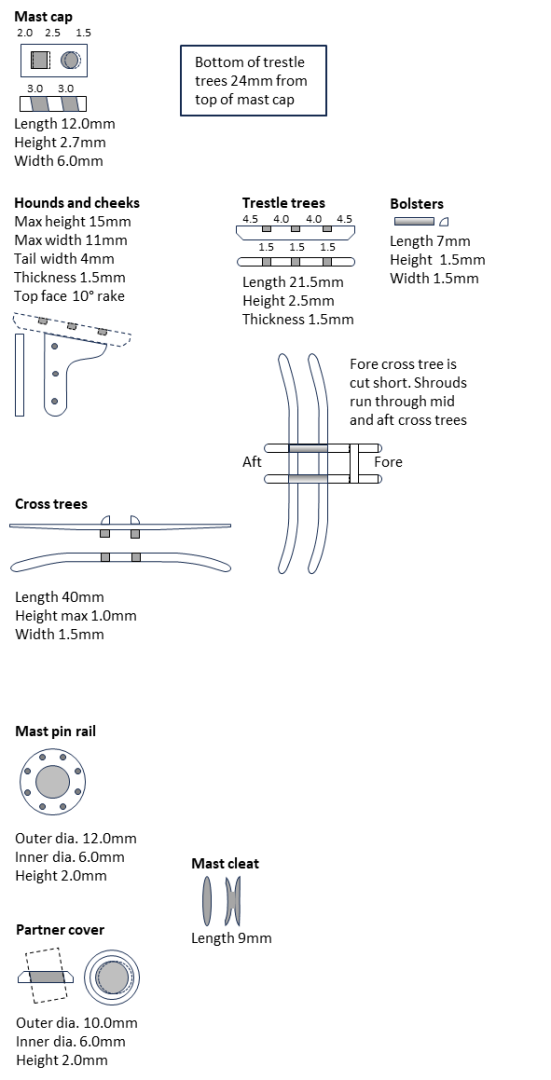
For the last two weeks my modelling effort has been at a computer screen with a pile of reference books next to me. The purpose? To draw the masts so that I can start building them. As Phil has mentioned on his posts, there are a good number of near-contemporary references which give different answers about sizes and shapes; the number of options appears to be more than the number of authors. I have relied mostly on Lever and Steel for contemporary records and on Marquardt (Global Schooner), Petrejus (Brig Irene), and Peterssen (Rigging) for recent opinions, and then made my own decisions. The drawings for the fore masts (lower mast and topmast) are below and the main masts are similar. The numbers on the left are distances from the top or from the deck. A number with a description such as '5.9mm round' give the cross section of the mast. Comments in italic show various features. Partner cover. This tarred, canvas cover is to stop water entering the hull around the mast. Making one from wood will be tricky. Has anyone invented a clever way of doing this? Pin rail. This has eight belaying pins and I have placed it perpendicular to the mast and not parallel to the water line. One cleat below it is for the spread yard truss. Any objections or suggestions for alternatives? Copper sheathing. I expect to use half of a hull copper piece on the mast: 6mm high and 9mm long is about right and the shipwrights would have access to them. Cross trees. My belaying plan has two topmast shrouds on each side, so two cross trees should extend from the trestles. I chose the aft and middle positions because they line up better with the lower shrouds. Does anyone have information to support this, or an alternative? Hounds. Phil made a good case for defining the hounds as the line where the trestle trees rest on an extension of the mast. This is self-consistent and admirable but unfortunately several authors use hounds to describe the widening of the mast. This is apparent on the topmast which has hounds to support ropes without any trees. I think the dual meaning will remain and the only solution is to define it for your application. Eyes and bolts. I have not shown these on this iteration of the drawings and will have to check the belaying plan carefully before I do. Drawing for the fore topmast comes next. The stick is 4mm square at the heel and 1.5mm round at the top, and to paraphrase Steel it would be very wasteful of wood. He states that the normal practice was to add planking around the heel so that it fills the fore hole in the trees better. I plan to use a 3mm dowel and at the heel I will reduce the size to 2mm square then add planks on all four sides. The hounds on the topmast are octagonal and I will repeat a technique I used on Sherbourne many years ago. This is to make the mast without hounds, then wrap layers of glued paper around the mast to build up the diameter, and finally cut back the laminated paper to get the octagonal section. Christmas is coming and the physical mast making will have to wait until next year. Best wishes to all. George
-
methods for serving a thin rope
georgeband replied to georgeband's topic in Masting, rigging and sails
Thank you, Wefalck. I was taught as a physicist that a perfect sphere is a good first approximation to most things, and in this case a cylinder is even better. I use a 'gammoning' method to measure diameters and wrap 10 turns of thread around a dowel, push them together and then measure the width of the ten. I expect others have their own variants on this method which has more control than crushing a single thread between caliper jaws. The Sew All thread (No. 100) I have measured is 0.2mm diameter by this method and the Extra Strong thread (No. 40) is 0.3mm or 0.35mm depending on the sample. These diameters do not scale linearly with those from your formula so it is not a matter of adjusting the effective density. The larger Gutermann numbers are for finer threads and I suspect that the Gutermann numbers given on the minionsofcraft website might be the length of thread needed to get to a defined weight. Linen threads have their own actual density and packing (I don't see gaps between strands) and so will have a variant of the formula. My thoughts now are to continue with a pragmatic approach and measure and use the threads that I have. I might return to Excel later, after I have finished the belaying plans... George -
methods for serving a thin rope
georgeband replied to georgeband's topic in Masting, rigging and sails
The internet tells me that Gutermann Sew All thread, readily available in shops, is one variant of Gutermann Mara. Mara is from the Industrial division and Sew All is retail. There is a long reply from the Gutermann sales manager in the USA, in 2015, on this link. https://sewing.patternreview.com/SewingDiscussions/topic/92551 To save you the effort of reading it all here are two key excerpts. Most fabric stores carry Gutermann Sew All which is a Mara thread and the most common size is Tex 30. Mara from the Industrial division is the same thread construction, MicroCore Polyester, but the Industrial segment has Tex 19, 25, 30, 40, 60, 100, 200 265 and 400. This link is for an on-line store where they describe the many variants of Gutermann thread. https://www.minionsofcraft.co.uk/blog/essential-guide-to-gutermann-threads. The thicknesses are shown as a number but I don't have a conversion scale that converts the number into a diameter. The extra fine polyester thread is No. 150 and the extra strong thread is No. 40. George -
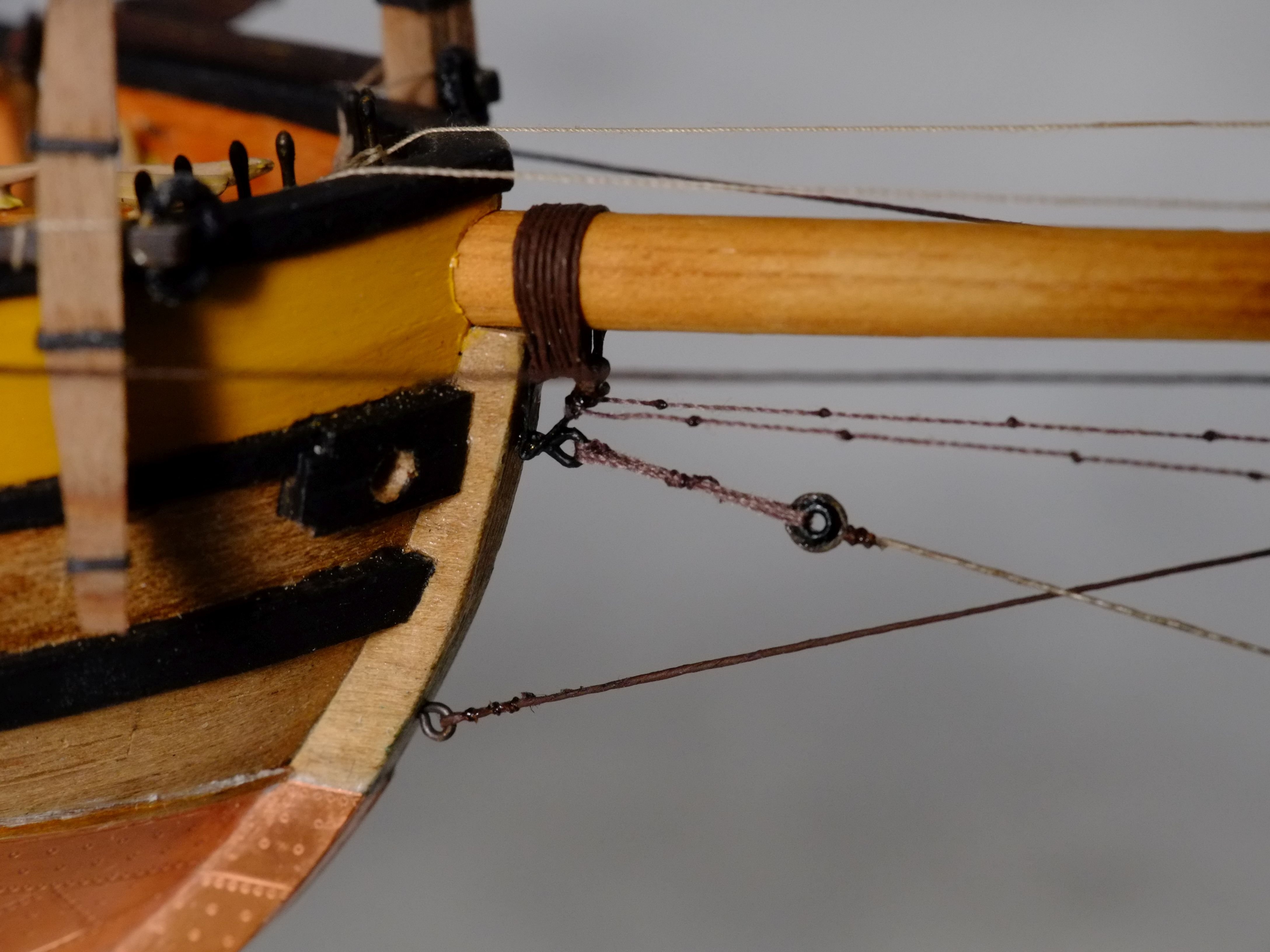
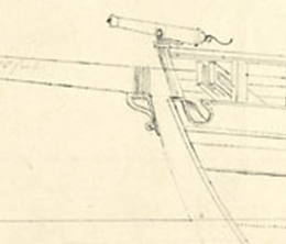
I have reached a minor milestone and the bowsprit assembly is now attached to the hull. The box in which I keep Whiting has also had an extension to accommodate the new spar. Part of the delay has been from deciding how to simulate a served (or serviced or dressed) rope and there is a separate thread about that. The answer for me is to paint a linen thread, or paint one of the fine ropes from Ropes of Scale for something like a shroud which is only served over part of its length. Painting Gutermann polyester sewing threads gives a rough and bumpy finish because the threads are too hairy. Little alterations to the belaying plan also took up many hours which I have not logged. Making and fitting the bowsprit assembly took 49 hours spread over one year. The gammoning loops through a metal bracket which was inspired by one I saw in Admiralty drawing ZAZ6112. This drawing could be an early proposal for the Fish class schooners. The bracket is also a convenient place to belay the martingale and the horses. ZAZ6112 extract I replaced the bowsprit shrouds that I had prepared previously and attached the new, painted, linen ropes to their deadeyes with seizings which look much neater. The outhauler tackle in the photo below is a bit slack and has been tightened now. The next step for me is to prepare drawings for the fore mast (lower and top). I have the basic dimensions - lengths and maximum diameters - but I know I will spend hours working out all the details and modifying the belaying plan. George


-
methods for serving a thin rope
georgeband replied to georgeband's topic in Masting, rigging and sails
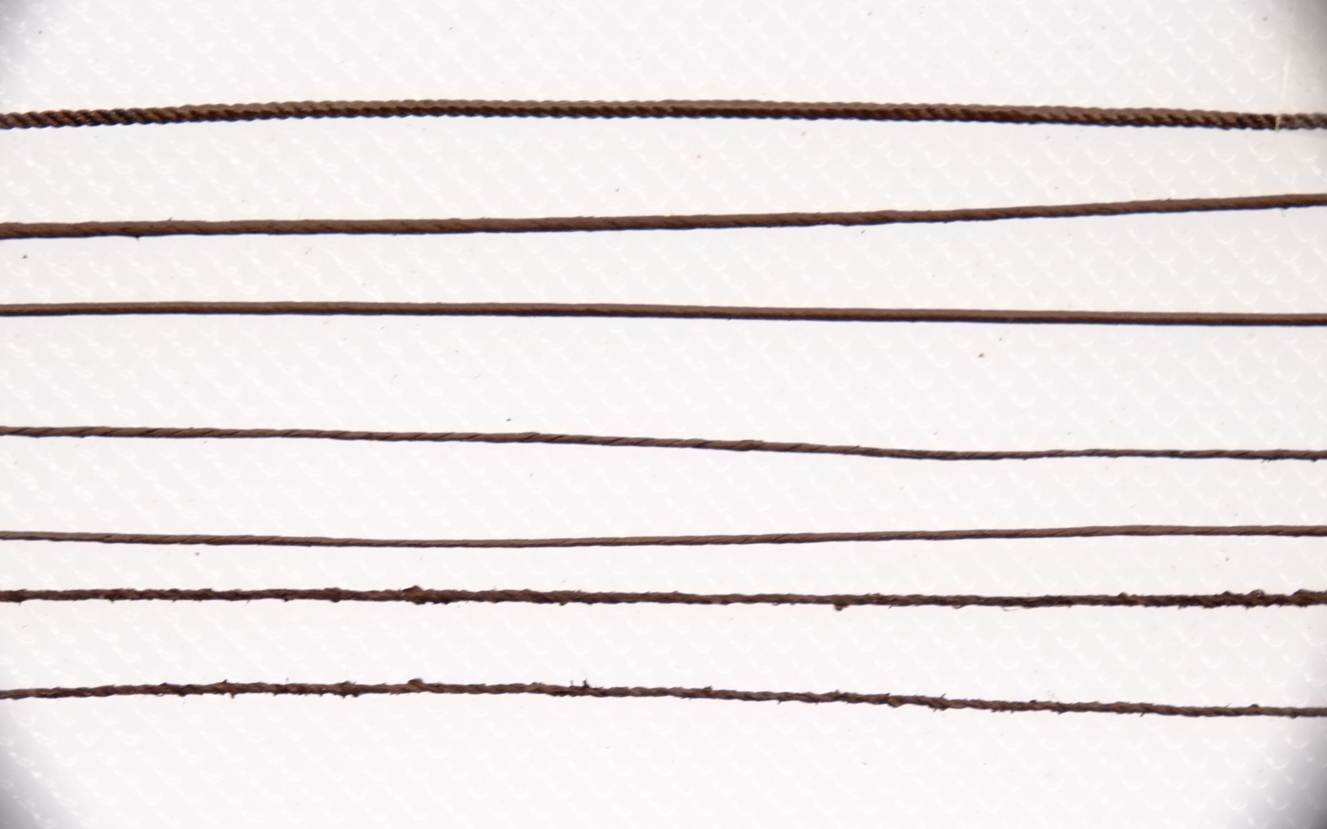
The Gutermann threads that I have been using are from a local sewing shop and their sizes (my measurements) and labels are 0.4mm Top stitch (polyester, three strands, quite loose winding) 0.3 - 0.35mm Extra strong (polyester, two strands) 0.2mm Sew-all (polyester, two strands) 0.4mm linen I don't know how these names relate to Gutermann Mara and they might have different specifications or it might be down to marketing in different regions. We have had a burst of sunshine here and I took some backlit photos of the threads above. This method is the best that I have found for revealing hairy threads and the results were not what I had hoped for, but do explain why painting some threads gave a rough finish. The linen thread is on the right. It could be that Dafi's white glue and spit is a magic formula that holds down the fibres. Waxing would also hold down the fibres but it would, I expect, prevent a water based paint from sticking. The smallest seized size I need is 0.4mm so I shall continue with the linen threads. George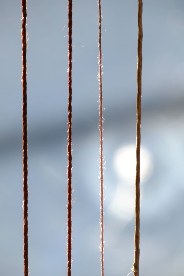
-
methods for serving a thin rope
georgeband replied to georgeband's topic in Masting, rigging and sails
Wefalck, Thank you for your kind comments and suggestions. I have tried painting the threads again in a more controlled way and found some interesting results. Gutermann polyester threads. These repeatedly show roughness after painting with acrylic and I can only think that this is from loose fibre ends which catch the paint and then stick out. I even tried dirty water as a first coat and that did not fix it. The Ropes of Scale ropes that I have tried use the same Gutermann thread but take the paint well so there is something curious here. Linen threads. These work well with paint though there is a directional effect: brushing in one direction smooths down any loose fibres and sticks them with the paint, brushing in the other direction lifts loose fibres and creates a bump. The diameters of any linen threads that I have tried are not increased significantly by painting and the largest increase in diameter that I have measured is 0.02mm. Both of the Gutermann linen threads I have now measure at 0.40mm diameter before painting and 0.42mm after painting. Gutermann cotton thread takes the paint better than the equivalent polyester thread. I was not expecting this, but both are too rough to use. One useful side effect is that the painted thread holds it shape quite well if it is bent or stretched taut. Wrapping 0.4mm painted linen thread around a 2.5mm deadeye and then seizing the ends together with fly-tying thread was quicker than I expected. George -
methods for serving a thin rope
georgeband replied to georgeband's topic in Masting, rigging and sails
Inspired by Dafi's success, I have simulated serving ropes with paint. First I tried Humbrol 'service brown' acrylic which is a reasonable colour for what I want but it is definitely gloss. In fact it is too glossy to use as a top coat though it is good at filling the contlines. (The contemporary spelling of contlines is not acceptable now, but have a look in Steel or the naval dictionaries if you want to see it.) I found some matt burnt umber acrylic ('Pebeo origin') in a local Hobbycraft shop and tried that. The colour is good and it is matt and is now my preferred approach for serving these fine lines. The method works well on linen threads but Gutermann polyester threads become very rough and are not useable. The threads in the photo below are, from top to bottom, Ropes of Scale 0.6mm, dark brown. The left end is bare, then there is a stretch with a single coat up to the middle, then two coats. It needs another coat to smooth out the lay. 'Hemline' linen thread, 0.7mm, dark grey. I bought this from a local sewing shop. Black '2 ounce' linen thread, 0.6mm. This was donated by my wife and is probably a family heirloom. Gutermann linen thread, 0.4mm, 7202 black. This carries the paint well. Gutermann linen thread, 0.35mm, 4010 brown. I expected it to be the same diameter as the black thread but there must be some batch differences. Gutermann 'top stitch' thread, 0.4mm, 696 brown. The thread went rough and lumpy with the paint. Not useable when painted. Gutermann 'extra strong' thread, 0.35mm, 696 brown. This also went rough and is not useable. For ropes that have both served and un-served sections I will use the Ropes of Scales threads and paint on the serving where needed, for example on the shrouds where they go over the mast heads. I am tempted to apply a coat or two of the gloss Humbrol paint first then finish with the matt. Ropes which were served on their whole lengths will be linen threads with the paint. I have not measured the diameters of the painted ropes yet. That's a job for another day. George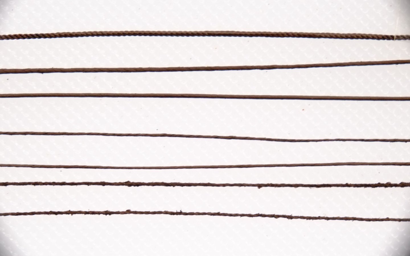
-
methods for serving a thin rope
georgeband replied to georgeband's topic in Masting, rigging and sails
Thank you to all for your suggestions. I followed the link from Wefalck to Dafi's HMS Victory and was overwhelmed by the quality of his work. Layers of PVA followed by paint seems to be one answer which suits my desire to avoid building and learning to use a serving machine. My speed of building is very slow already and I do not want to add more delays. George -
methods for serving a thin rope
georgeband replied to georgeband's topic in Masting, rigging and sails
Paul, I admire your skill in working with such fine threads which clearly proves that it can be done. The question that I return to is more philosophical: how much should we follow old, full-size practice for a model? Is there a simpler way to create the same effect? My models are plank on bulkhead so I have clearly abandoned the idea of building all the frames which are not visible on my finished models. Respect to those who build frames, even if they are not in oak! We all draw our own line in the sand to show what we want to do 'properly' and I am exploring how I want to make a rope look as if it has been served. I will experiment with paints at some point to see if I can get a smooth finish. George