georgeband
-
Posts
307 -
Joined
-
Last visited
Content Type
Profiles
Forums
Gallery
Events
Everything posted by georgeband
-
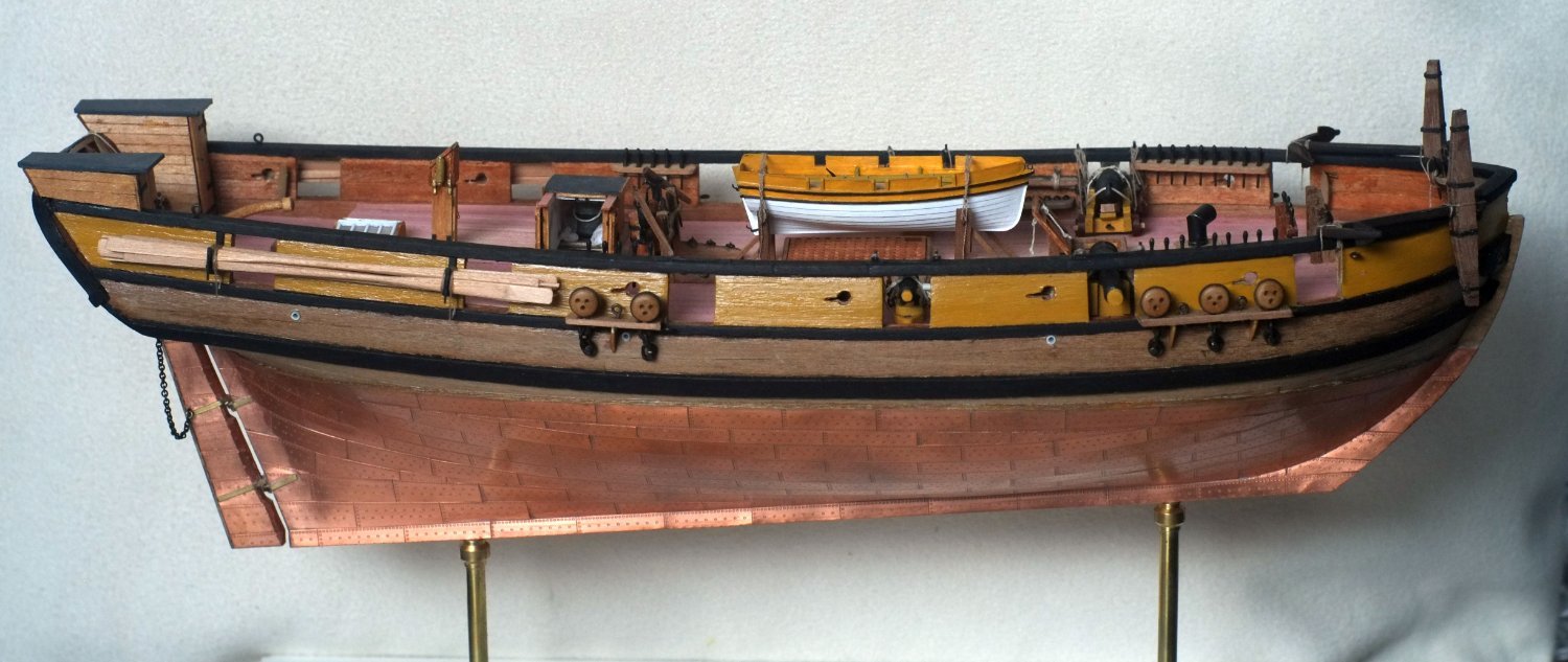
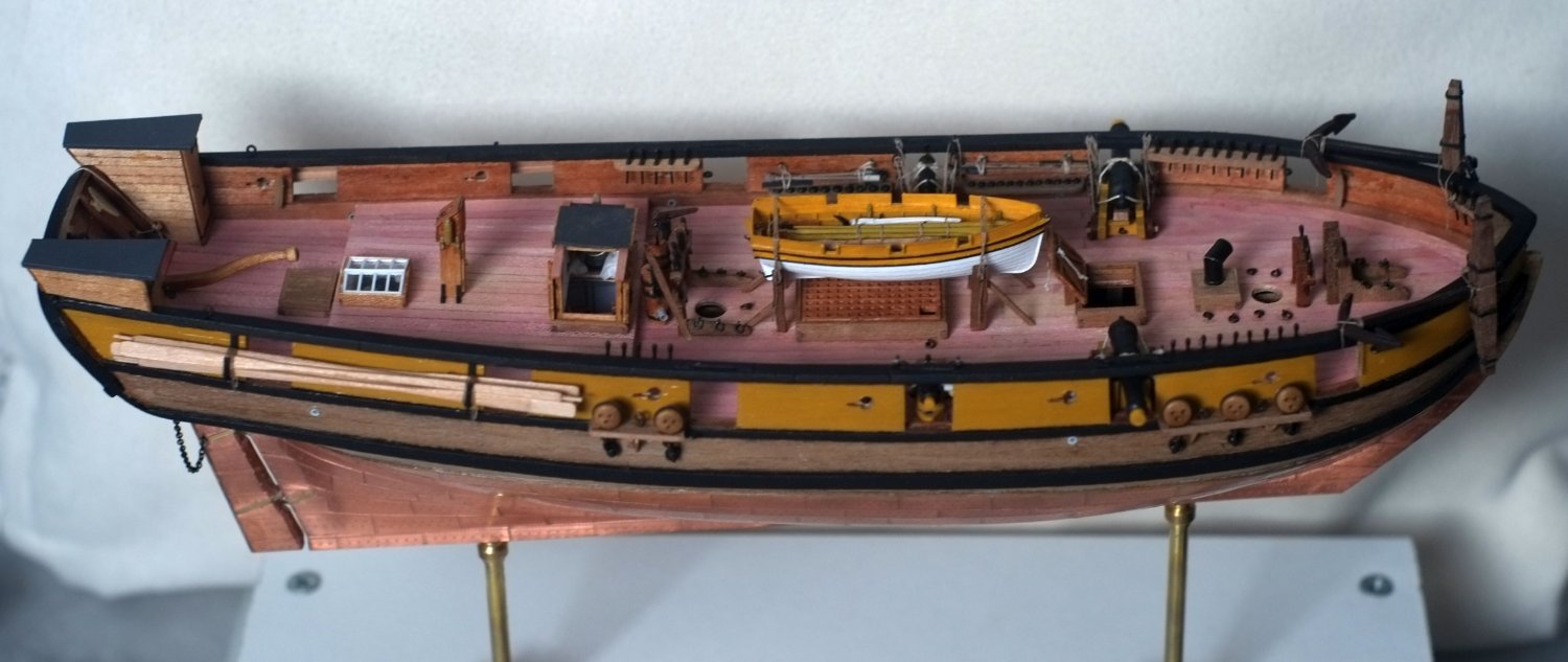
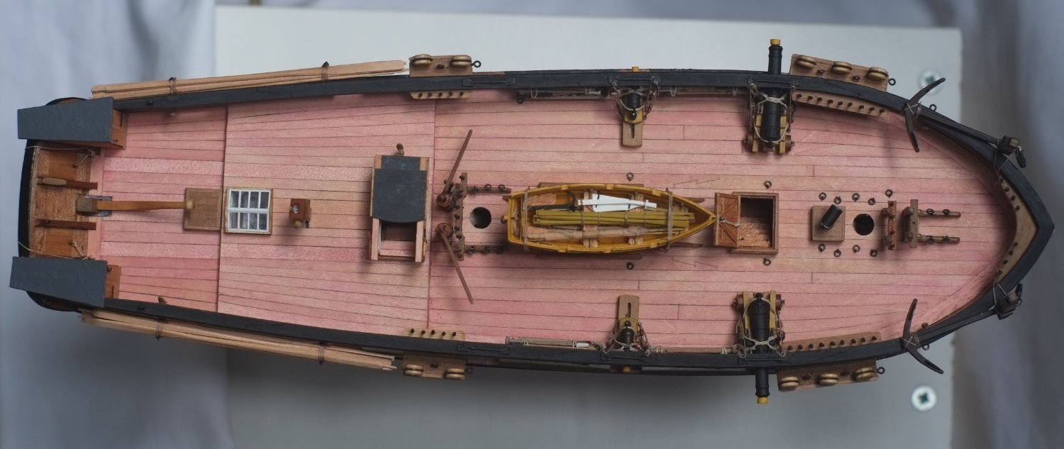
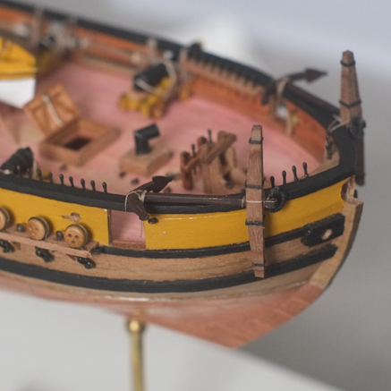
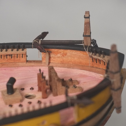
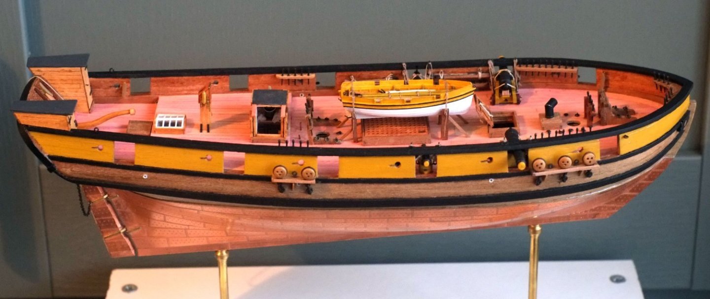
 A few photos to show a milestone in the build. (The pumps are standing loose at the moment so I can move them out of the way when rigging.) As I said above, the next big job is the masts and everything that goes on them. George


-
My experience with Caldercraft dowel and plywood has not been very positive. The keel and bulkhead parts were a very loose fit and measurements showed that the ply was 3mm thick and the slots were 3.2mm wide. It suggests that someone thought that 3mm and eighth inch looked the same and could be substituted. Similarly, the dowels were too big to go into the slots in the keel though that problem was easy to solve by sanding a couple of flats on the dowel. I hope that Caldercraft has improved since then. I agree with comments above that the dowels will acquire various tapers (and even octagonal sections) when they become spars and a small difference in the size of the original stock is minor. If you do want to reduce a diameter then grip the dowel with sandpaper and thick gloves and either spin the dowel with an electric drill or rub the sandpaper up and down along the dowel while slowly turning it with your other hand. I don't like the noise of a drill and use the manual method. For tapering I have used a small plane to get the basic shape right. George
-
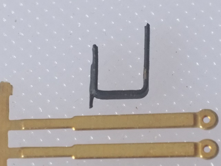
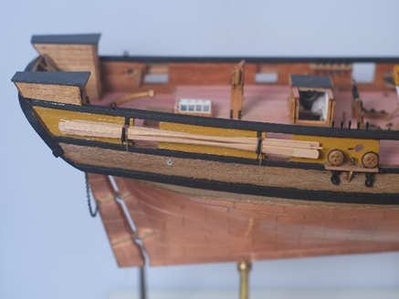
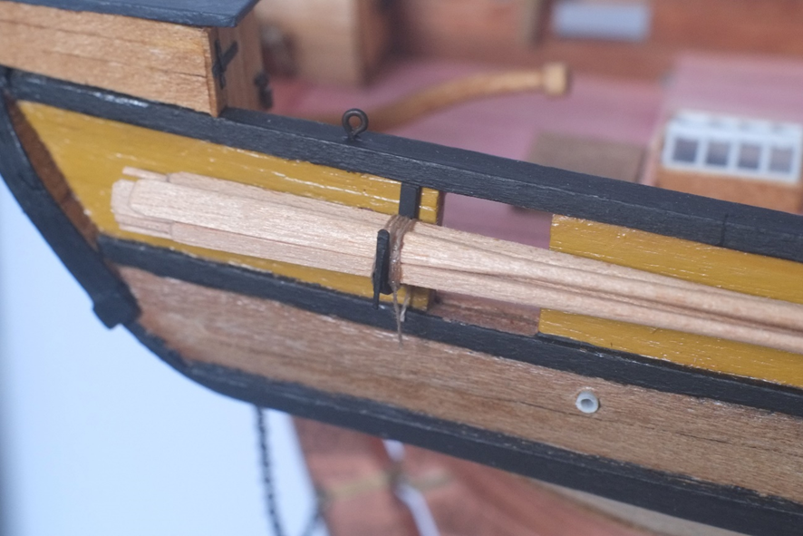
Sweeps continued I made brackets from the etched brass 'chains' that came with the Ballahoo kit. I cut off the eye and filed all the edges smooth. The narrow section is then bent through 90° to form a 4mm long upright. A second right angle bend defines the base which is just over 4mm long internally. The remainder is a longer upright that will be glued to the bulwark. I glued a short length of thin, scrap, etched brass fret to the narrow section so that it projects a little below the base and is there to stop a lashing rope from riding up the side. The brackets are painted black. I glued the brackets between the gunports and their adjacent sweep ports with the top touching the underside of the gunwale. This looks reasonable and supports the oars in a balanced way. There are six sweeps on each side, three with their blades forward and three with the blade aft. I tried to arrange them in a cleverly designed pattern but gave up and let them fall into a natural arrangement when I tightened a thread around them to hold them to the brackets. I tied the ends of the thread with a reef knot and let the ends hang down. The hull is now mostly complete. The remaining additions will be Some figures to give a sense of scale. I have Captain Amati and his crew already. A spare spar or two, probably tied on top of the gunwales at the aft end of Whiting. The anchor rope on one side. Refitting the pumps that I took out while building the housing over the main ladderway. Making drivers for LED lights that connect to the optical fibres I installed to illuminate the interior. The masts and spars and sails and rigging are the big job that will wait until my next modelling season because I will need to change direction and concentrate hard. Lots of judgement calls needed for them. George
-
Research for a model often becomes historical research and a pleasure in its own right. This happened for me with the schooner HMS Whiting, built in Bermuda in 1805, which according to Wikipedia was captured twice in 1812 when her history comes to a halt. I had a lucky discovery with a commentary on a legal case that linked Whiting to her new identity as a privateer in the service of the nascent Republic of Cartagena. Her new name and captain's name opened other routes for research which takes her intriguing story to the beginning of 1814. The 1805 Club published my paper on this topic in its journal The Trafalgar Chronicle. I have attached a copy. George HMS Whiting as San Francisco de Paula.pdf
-
- 8
-

-

-
Thanks for the information, Ollie. At the moment I feel seduced by the idea of a rope walk and am parking the anchor rope for later. George
-
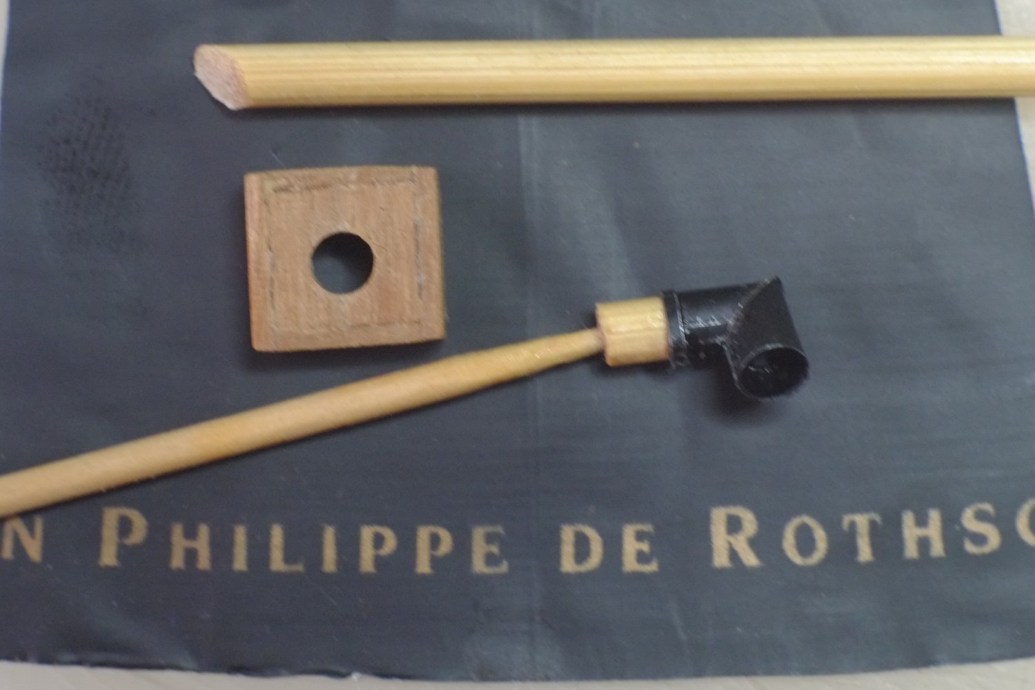
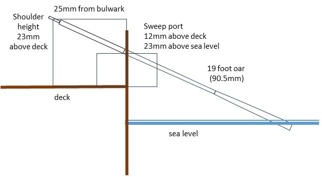
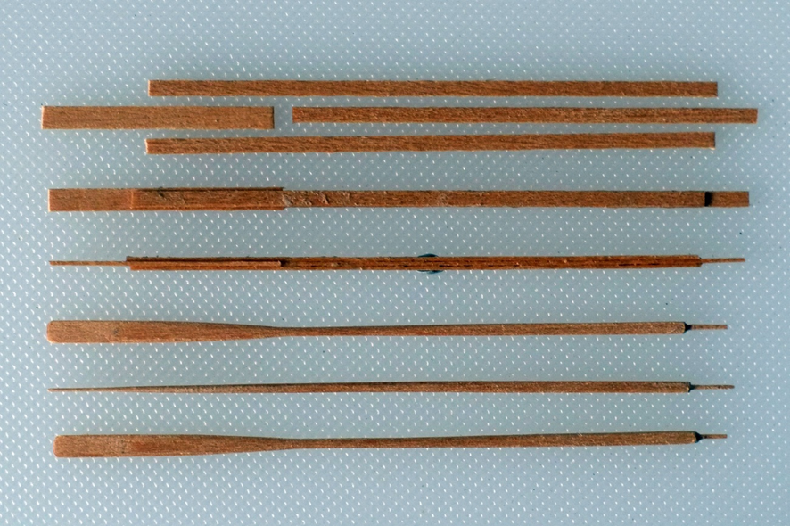
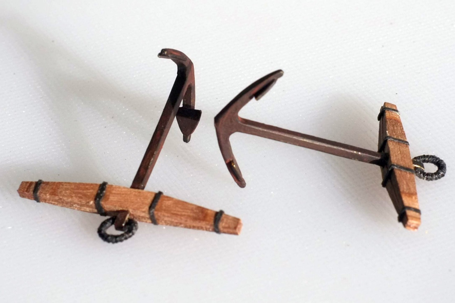
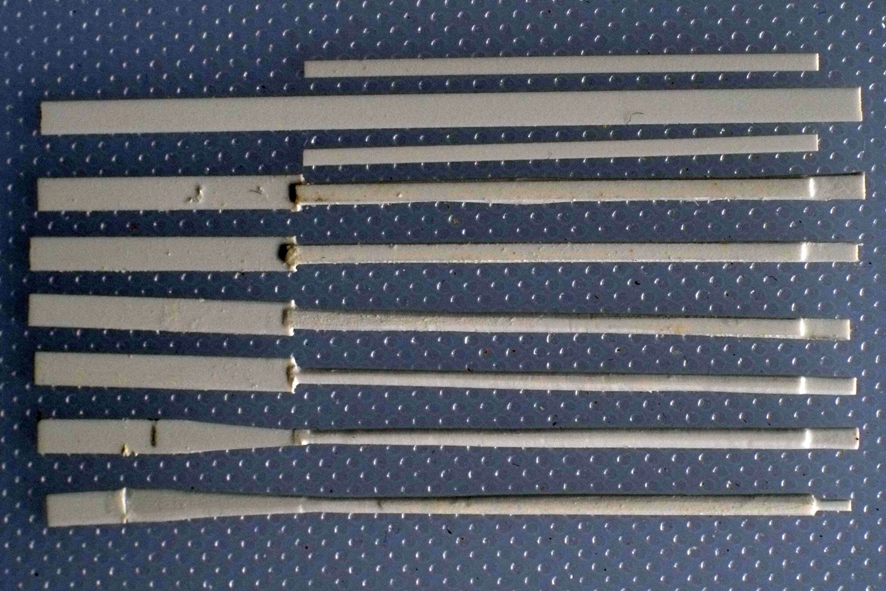
Anchors stowed I have tied the anchors to the gunwales on Whiting so they are safely stowed. The crown is lashed with a rope through a gunport, and the stock is tied to a belaying pin which was spare on my belaying plan. I might yet add an anchor rope to one of them, leading from the hold through a hawse hole. It all depends on finding or making a suitable rope and that can wait awhile. Sweeps Discussions on another post have convinced me that I need to show the sweeps stowed somewhere on Whiting. A sailor would stand and most probably push the sweep to use it. His shoulder height for pushing would be about 23mm (1.47m or 4' 10"). Measurements of the (crowded) deck of Whiting show that a sailor would be about 25mm from the bulwark, depending on which port he was working. The sweep ports are about 23mm above the waterline and 12mm above the deck. A scale drawing shows that a 19 foot oar is the right length and has the right proportions to be used on Whiting. A comprehensive account of oar construction is presented in The Art of Making Masts, Yard, Gaffs, Boom, Blocks, and Oars by David Steel, 1797, which can be found on https://www.thebigrow.com/?p=659#more-659 . The tables of dimensions given by Steel for a 19 foot oar are summarised in the drawing below. I made the sweeps by laminating strips of wood and then carving them to shape. It is a slow process and took me nine hours to complete 12 sweeps. I used maple strip because it is close grained, I like the colour and it was available in the right size at my local model shop. Most of the parts for the lamination are 2x0.5mm except for the blade which is 3x0.5mm. The central layer is 61mm long. Make a pencil mark 6mm from one end on both sides to indicate the handle. The outer layers are 77mm long. Glue one to the central layer so that the core protrudes by 6mm; the outer layer extends a lot further at the other end. Clamp the layers together and leave until the glue has grabbed. I use a slightly diluted wood glue. The blade is a 31mm length of 3x0.5mm wood. Glue it to the outer layer ensuring that it presses tight against the core layer. The second outer layer can also be glued on now and the whole assembly clamped. Check that the laminations are aligned from side to side otherwise the loom might have a trapezoid instead of a square section when you start sanding later. The carving begins when you are certain that the glue has cured. 1. Sand the body and loom to a square section, 1.6mm to a side. I rested the assembly on a small block of wood and ran a sanding stick over it. Check the size frequently until you get a feel for how quickly the wood is cut back. 2. Taper the outer layer over the blade so that it blends smoothly into the blade. Continue the taper into the body. The thickness at the beginning of the blade is 1.2mm. 3. Taper the body in the perpendicular plane so that it has a square section which reduces to 1.2mm at the blade. 4. Round the body but keep the loom with a square section. I tried sanding and scraping with a knife blade and both methods work. 5. Taper the edges of the blade and round off the sides so they merge with the body. 6. Cut the end of the blade 86mm from the join between the handle and the loom. There are variations on the shape of the end and I rounded the corners. 7. Cut back and sand the core to form a handle. It is slightly undersize for diameter but not enough to notice. When you are satisfied with the rounding of the handle cut it to a length of 4mm. I also bevelled the corners of the loom next to the handle. The sweeps were probably stored on iron brackets fixed to the outside faces of the bulwarks. Near the stern is most likely because the chains for the rigging take precedence elsewhere. My next task is to design and build some brackets. George

-
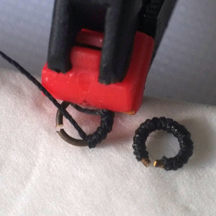
Anchors I have not found a definitive statement about the size of the anchors on Whiting. A general formula that has been repeated in contemporary books is 1cwt (one hundredweight or 112lb) for every 20 tons burthen. Other books give other weights and at least one (Hedderwick, 1830) complains that there are no standard formulae. Whiting was 70 tons so 3½cwt anchors are probably correct. The anchors supplied in the Ballahoo kit are 12cwt and somewhat large. The wooden stocks also look to be too long relative to the metal shank. I consigned mine to the spares box. Caldercraft sell a 3.5cwt kedge anchor which should be just right according to the general formula. I bought two and when I measured the shank I found that it is closer to a 4cwt anchor, but that is quite good enough. Wood stock The cross section of the assembled stocks should be 3.2mm square at the centre section and 1.6mm square at the ends. The halves need to be tapered on the outer face and that reveals a problem: the stocks are cut from walnut plywood and the taper exposes the cross-grain layers in the middle of the sandwich. I chose to live with this blemish. I marked the ends of the full size, central section (up to the inner iron bands) with a pencil line on the outer face, away from the slot for the shank. Simple carving removed most of the wood, reducing the thickness to 1mm at the ends, and then careful sanding gave a smooth surface. The joins between the ply layers are useful guides to show if you have removed consistent amounts of wood. The ply is weak at the slot for the shank and I broke one half-stock but repaired it with glue. Metal castings The castings are from a fairly soft alloy so it is easy to clean up the flash with a file. I rested the casting on a small block of wood while filing it, using the end grain of a piece of softwood to catches the filings as they come off. The bumps and neck near the top can be filed flat following the lines of the shank. I tested the fit against the stocks and stopped filing when the shank could enter without straining the wood. Use two stocks to check the size of the shank in the perpendicular direction. Clamp the shank between two stocks and there should be a small gap between them, small in this case is about the thickness of a piece of paper. If the gap is bigger then file back the shank a bit more. I put a small chamfer on the edges of the shank. The ends of the arms can be made more pointed and neater. Drill a 1mm hole for the anchor ring. The hole has about 0.5mm of metal to each side but more above it towards the end of the shank. The palms are tidied and fixed to the arms with superglue. I painted the finished metalwork with enamel as a primer then used a dirty black with washes of burnt sienna to simulate rust. A glimpse of bare metal on a corner where the paint gets chipped off looks good to me though it's easy overdo this. Ring I made the rings by winding the suppled 0.7mm brass wire around a round, metal mandrel which happened to be the handle of a file. A drill bit of about 3mm or ⅛ inch is about right. Snip out a circle and it should have an outer diameter of about 5mm. The rings had a puddening to protect them. I used Caldercraft 0.4mm black thread (it is labelled as 0.5mm) which is oversize for this application but a finer thread would simply look like a thicker, rough ring. I held the ring in a clamp, gripping the ends, and made three turns of thread around the wire, opposite the gap. Adjust the turns so they are snug against each other, hold the thread ends taut and apply a drop of superglue which wicks into the thread and sticks it to the wire. Do not let it wick into the stretched, straight thread because this will harden it and stop it from wrapping around the wire. About 12cm (5 inches) of thread is plenty for one ring. Adjust the position of the ring in the clamp and make several more turns of the thread around the wire then fix them with superglue. Continue like this until you reach the end of the wire. Leave about ½ mm of bare wire and trim off the remaining thread. Now repeat the exercise for the other half of the ring. Assembly Open up the rings so that the gap between the ends will fit across the shank. Make sure that the ring is flat and not twisted otherwise it will sit at an angle to the shank. Hold the ends of the ring over the drilled hole then squeeze them together with gentle pressure from pliers. The ring should be able to move. Check the fit of one half-stock and fix it to the shank with superglue. Now apply a drop of wood glue to each end of the half-stock and position the other half-stock. Clamp the ends together and leave the glue to set. Apply a small drop of superglue to the join between the shank and the second half-stock while you are waiting. The iron bands around the stock are cut from thin black card. You need about 10cm or 4 inches for each anchor, a little under 1mm wide. I marked the positions of the bands in pencil on the stocks. Apply a thin bead of PVA or wood glue to the card and, starting at the underside, wrap it around the stock. I overlapped the card on the bottom face with the ends at the corners of the stock. Rope The size of the rope is poorly defined and a rule in one book is contradicted by another. The AOTS book for HM Cutter Alert states that she had an 8" rope for her 3cwt kedge anchor. If this size anchor is the main one for a vessel then the rope could be thicker because it has to work in harder conditions than just kedging. The 8" circumference translates to a model diameter of 1mm. The ropes for anchors were generally cables (or cablets if they are small) which have a left hand lay unlike most ropes which are right handed. Most people do not notice the difference but model making pedants want it to be correct. This might be the time to build a rope walk, or stow the anchors without any rope tied to the ring. Can anyone recommend a supplier for 1mm diameter rope with a left hand twist? George
-
Thanks Frolick and Chapman for all this information. It provides lots of evidence that sweeps were carried and used and pushes me towards stowing some, somewhere, rather than missing them out. George
-
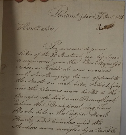
Phil, It all looks very plausible and the descriptions I have read about fishing show that there were many variations. I like the way that you attach a short length of rope-with-an-eye to the anchor cable with nippers in the same way as a messenger cable. The method that sits in my mind is to wind the rope-with-an-eye around the anchor cable and dispense with the nippers. The far end of the rope only needs a half hitch to stop it from unwinding. I cannot remember where I saw this explanation and it might have been about fixing eyes or hooks to the anchor cable to use as stoppers. I will have a look in some references later. The letter below is attached to ZAZ6118 (Greenwich drawing of Haddock) and is not on their website. The last line confirms that a tackle was used to weigh the anchor. No mention of how the tackle was attached to the anchor cable... George
-
Well said, Phil. Model building is similar to DIY projects in that simple jobs can sometimes take hours. The opposite, on the rare occasion that a job goes quicker than expected, is a joy to experience. George
-
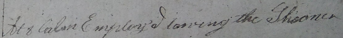
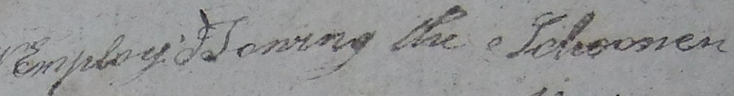
Thanks all for your comments and suggestions. There is a log book entry for 18 June 1806 which states that on two occasions in a calm that day the crew were 'employed towing the schooner'. They apparently preferred to hoist out the boat and row that rather than use the sweeps on the schooner. As Druxey says, the sweeps might have been for extreme circumstances. (It is definitely 'towing' and not 'rowing'.) I wonder if the sweep ports were standard items in a contract and the various vessels had them, but the captains chose not to use them. A logical consequence would be that the sweeps (if provided) would be disposed of because they were yet more clutter on a busy deck. I think this is going to be a judgement call for my model since I do not have firm evidence either way regarding the presence or absence of sweeps. Chapman - thank you for the links. As an aside I have been looking for a clear picture of a 'mystico' and the one in your first link is excellent. You have solved a different problem for me! Wefalck - You provide valuable circumstantial evidence which goes into the eventual balance of probabilities decision about sweeps. George
-
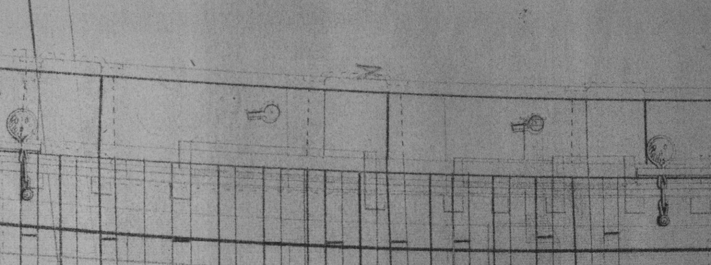
Admiralty drawings of smaller vessels often have keyhole-shaped features on the bulwarks which I have assumed are ports for sweeps. The example below is from ZAZ6116, the schooner Haddock, and there are six on each side. Am I right in my assumption that these are sweep ports? The tables and drawings for sweeps in Steel https://www.thebigrow.com/?p=659#more-659 are quite extensive. For an 80 ton vessel he gives a total length of 25 feet of which 11 feet are inboard (handle plus loom). The deck on one of these schooners is very cluttered and it looks to me as if the inboard length should be a lot less otherwise the sweep cannot be used with a full stroke, especially when holding the handle. I could guess 20 feet as the maximum total length, which brings me to another question. Where are the sweeps stored when not in use? The only available space on my model of Whiting (same class as Haddock) is on the gunwales, leading forward from the transom. There are two convenient square ports where a rope can be passed through to lash the sweeps on top of or hanging from the gunwale, inboard or outboard. The geometry of the schooner would make it very difficult if at all possible to pass the sweeps into the hold so I cannot avoid the problem by claiming that they are 'below'. Any information would be most helpful. George
-
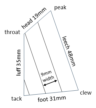
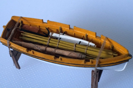
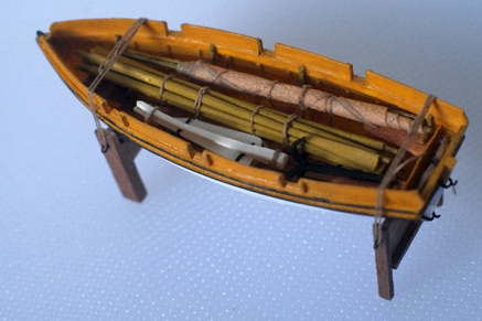
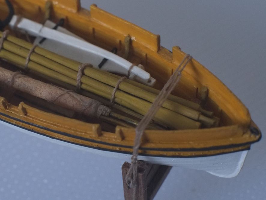
Oars and sails and stowing Oars A comprehensive account of oar construction is presented in The Art of Making Masts, Yard, Gaffs, Boom, Blocks, and Oars by David Steel, 1797, which can be found on https://www.thebigrow.com/?p=659#more-659 . I used this as the basis for my oars and combined the entries for single banked boats with those for sculled wherries and skiffs. No doubt there were local variations in the design and manufacture of oars and the results of this research should not be regarded as a universal truth. (dimensions in mm) I made the oars from three layers of polystyrene strip. The centre strip is 2.0x0.5mm (80thou x 20thou) and is 50mm long. The outer strips are 1.0x0.25mm (40thou x 10thou) and 31mm long. The task is largely one of sanding, filing and carving and I like to think of it as 'micro whittling'. I painted the oars to give a wood effect then cut away the ends of the blades, trimmed the blade tips and touched up the paint finish. Grapnel and boathooks These are etched brass items from Caldercraft. I added a coil of rope to the grapnel. Sail I wanted to show the mast, yard and sail dismounted and stored in the boat. A drawing of a sprit sail in https://boatbuildercentral.com/support-tutorials/Tutorials/sprit-rig.pdf and some thinking suggested that the sail would be wrapped around the mast and the sprit yard inserted in the last few turns. The sheet from the lower corner (clew) of the sail could be wound around the sail to hold it, in the same way as the gaskets are used on a square sail. The size of the sail is also my guess. Sprit sail The mast is from 0.5mm diameter brass, 45mm long and painted to look like wood. The sprit yard is from 0.3mm diameter brass, 41mm long and also painted to look like wood. Only the ends will show. I made the sail from thin paper that was previously a tea bag. Different manufacturers use different papers and some have a distinct perforation pattern on them but I found one (PG Tips) that had no discernible texture. The slight brown staining from brewing the tea gave it an aged look. I drew the shape of the sail and the seams in pencil. It can then be cut out leaving a wide margin (about 1cm) on the luff (front edge). Fold the front edge over a ruler then put in the mast with about 2mm protruding beyond the top of the sail at the throat. Hold the sail and mast together and apply small drops of superglue to the sail where it folds over the mast. The glue grabs the mast through the paper and only a few drops are needed. The excess margin can now be cut off with a sharp knife. I folded over the peak (top corner) so that the head (top edge) is parallel to the mast. I glued a bolt rope to the leech (rear edge) from the clew up to where the sail folds over. A second bolt rope is glued to the last 10mm of the foot and left to hang as a sheet from the clew. I allowed about 10cm to hang free. Use PVA glue and let it dry before the next step. The sail is now rolled up around the mast. Keep the turns quite tight and continue until about 10mm to 15mm is left. Now drop in the sprit yard and resume turning until the whole sail is rolled. Continue by winding the sheet around the sail so that about three turns bring you to the top of the mast. Add two more turns as half hitches to secure the end of the sheet. I cut the sheet so that about 5mm was left free. The whole assembly is now ready to mount in the boat. Fill the boat There is a lot to put into a small boat and everything has to be tied down so that a rogue wave cannot wash anything out. It’s fiddly work. I started with the oars and boathooks which I gathered into a bundle, some pointing forward and some aft, and placed it on the thwarts with the head of the bundle tight into the bow. I looped a thread around the bundle and the thwarts to tie them together, no glue here! I used simple reef knots and left the ends to dangle down towards the keel, though they needed a small drop of superglue to persuade them to hang in the right direction. I had made seven oars and mistakenly included all of them in the bundle. I have left it like this because I did not want to risk damaging the boat to take one out. The rudder and tiller fit on the thwarts to one side of the oars and port was my arbitrary choice. I tied them down and even put the rope through the mortice in the tiller. No one will notice but I know. The grapnel fits into the boat on the same side as the rudder and I did not tie it in, reasoning that a large piece of ironwork will stay put if a wave splashes over. The rope coil tucks into the space between the transom and the stern seats. The sail and its mast and yard fit neatly in the remaining space to starboard. It is tied to the thwarts in the same way as the other parts. The securing ropes for the boat can be tied now. I used the same Guterman thread as elsewhere on this model and tied a 15cm or 6” length to the starboard eye on the cradles with a bowline hitch. The line goes over the hull, through the port eye then back over the boat where a ‘truckers hitch’ is formed. (There are lots of descriptions on the internet.) The difficult step is to tie a small loop in the rope about midway between the two wash strakes. Once this is done the rope is threaded through the starboard eye, then through the loop and then back down towards the starboard eye. I gave it a couple of turns around the tensioned ropes below the wash strake then fixed it with two half hitches. The free end hangs down and I cut the length so that it ends just above the deck. The boat and cradle is now ready to fit to the deck. This has been an enjoyable project in its own right. George

-
I made the galley chimney for Whiting from the same type of foil, though it was black on my bottle. It is a pleasant material to work with and I have also used it for 1/1200 scale sails. I keep a small supply in case it ever gets replaced by plastic. An alternative that I am planning for the masts when I eventually get to them is to bend copper plates left over from the hull. I am most impressed by the quality of your build, Phil. Well done indeed. George

-
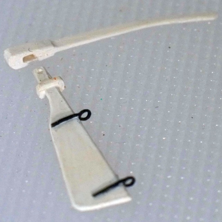
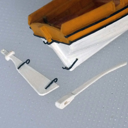
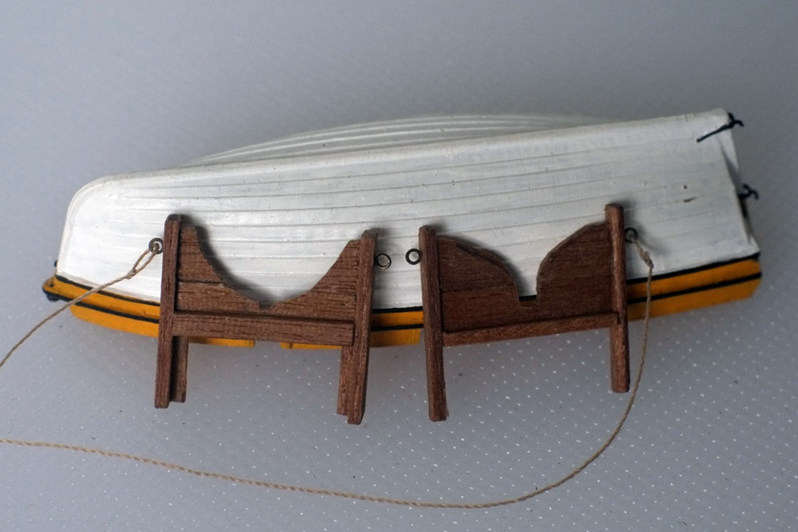
Rudder and tiller I made the rudder from 0.5mm thick polystyrene sheet and shaped it by eye, guided by several photos and drawings. The Admiralty drawings display a range of profiles so choose one that pleases you or design your own. The tiller is also from 0.5mm thick polystyrene and has a curve to it. The tiller on the Victory boat at Portsmouth had a mortise at the end which is built up from extra layers of wood. It sits over the top end of the rudder and is locked into place by a peg that passes through a hole in the rudder. I replicated this on my tiller and also added a rim around the rudder to stop the tiller from slipping lower. I painted the rudder and tiller white. The rudder hangs from the boat on two gudgeons and pintles. I made the pintles first from scrap offcuts of etched brass – I looked for a straight, narrow piece with a stub that projects to the side. The straight sections are bent to sit on the hull and the stub gets two bends so that it looks like a pintle projecting from the stern post. I painted them black then fixed them in place with superglue. I added two gudgeons to the rudder at heights which match the pintles on the stern post. I made the gudgeons from small, etched brass eyes painted black. Hold the eye with fine pliers then bend the tail so that it is closer to being a tangent to the round eye instead of perpendicular to it. Trim the tail to length and glue it to one side of the rudder. A separate length of brass goes on the other side of the rudder. The rudder and tiller will be stored in the boat and lashed to the thwarts. Cradle It was probably a job for the ship’s carpenter to build the cradle and I suspect that there were many designs. I chose vertical posts (relative to the waterline, not the keel) and glued short pieces of 1x4mm walnut between them. These should then be carved to fit the boat’s hull and I started with a cardboard template rather than attacking the wood straight away. I added a strengthening cross beam to each cradle and also planned for angled supports to stop them from tipping over. Eyes for lifting ropes I glued two etched brass eyes into the hull. The forward one sits in a hole drilled vertically into the stem post, between the wash boards. I placed the aft one inside the transom and also glued it into a drilled hole. Oars The Caldercraft etched brass oars are not really suitable: there are only four of them in the set and the shafts are far too thin. I am currently exploring how to make a set and will probably try laminating styrene strips. George

-
Thank you all for your photos, comments and interpretation. I have just had a look at my length of natural, untreated hemp rope from a distance of about 24 feet which is equivalent to a model viewing distance between 4" at 1/72 scale and 6" at 1/48 scale. I could not see any loose stragglers and will continue to aim for smooth ropes on my models, smooth meaning that I cannot see rogue fibres from 4" to 6" away. That is closer than I can focus without a magnifier, but it does mean that some of my close-up photos show ropes that should have had a hair cut. George
-
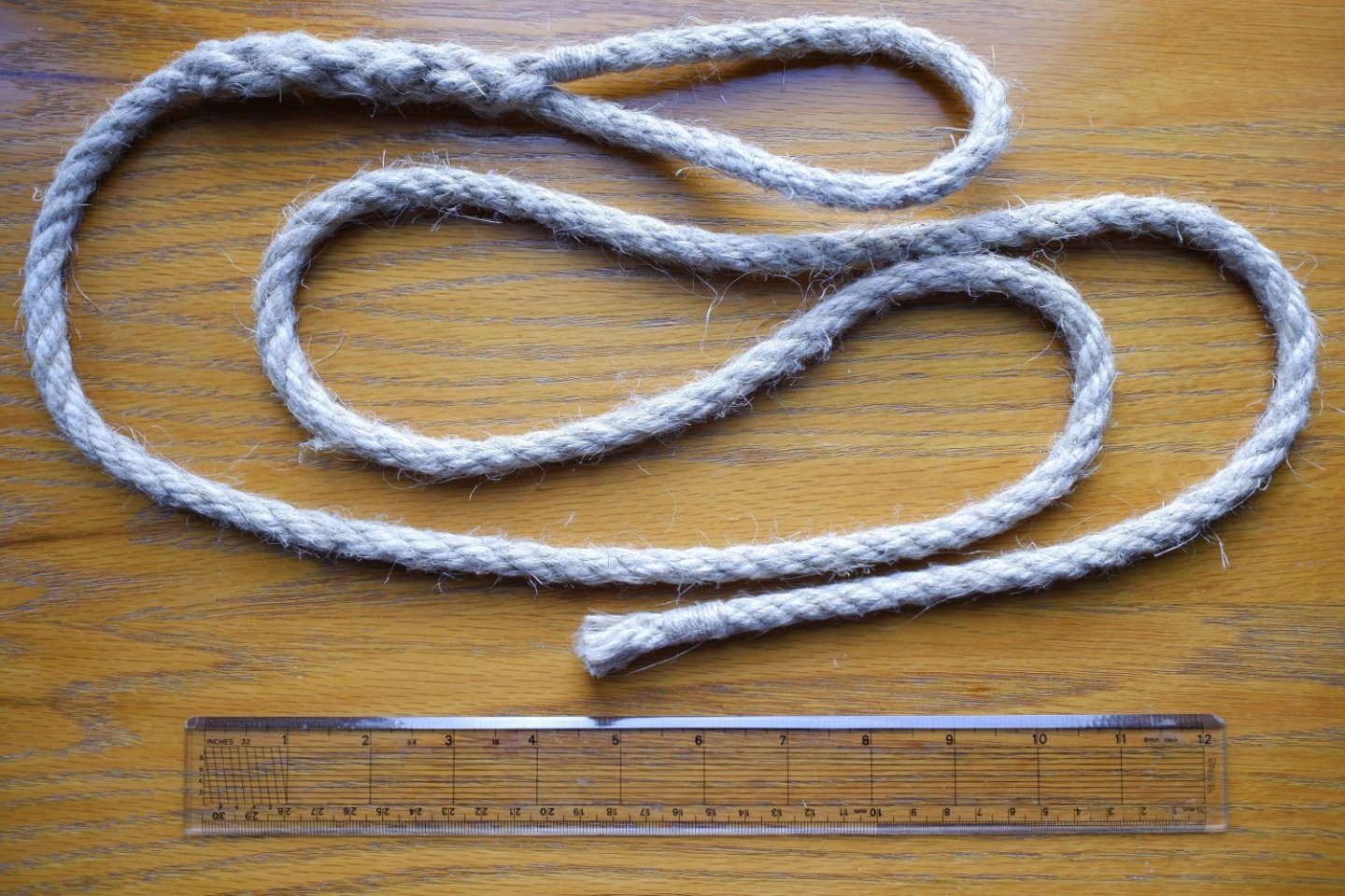
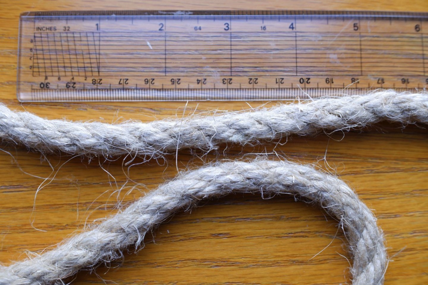
How hairy was a real rope and should we replicate it? The thread supplied in some kits is quite hairy and people devise techniques to smooth off the model rope, for example to pass it through a candle flame or to run it through bees wax. But how hirsute is a real rope? They must have some straggly ends that eventually break off and form the wisps on deck that become a job for someone to sweep up. I was in Portsmouth Historic Dockyard during the Trafalgar weekend and one of their volunteers made a length of hemp rope for me and spliced an eye into one end. Thank you to Len Cullen and the other volunteers who give their time there. This rope is about 3/8" or 1cm diameter, so it is one of the thinner ones on a ship. The rogue fibres are about 1" or 3cm long and are clearly visible on the photos below. Converting the lengths to a 1/64 scale model rope we get about 0.5mm as an acceptable level of hairiness, and a bit more on a 1/48 scale model. I guess that a thicker rope would have the same lengths for the hairy bits because it is formed from the same strands. Natural hemp ropes are not silky smooth in real life and a model with perfect ropes would please an artisan who prides himself on his workmanship but would look toy-like to someone who strives for realism. A cheap thread with 2mm or 3mm strands sticking out from it should, in my opinion, be brought under control but it does not need to be taken to extreme smoothness. On standing rigging the tar or pitch (I cannot remember which) that coats it would act like a hair gel and stick down the loose fibres. It is reasonable to make our model ropes smooth when they represent standing rigging. Does anyone have photos of ropes made in other materials for comparison? George
-
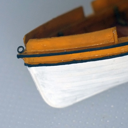
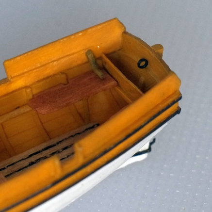
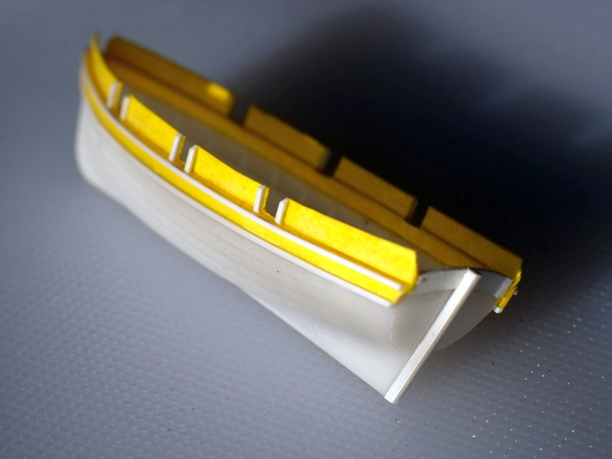
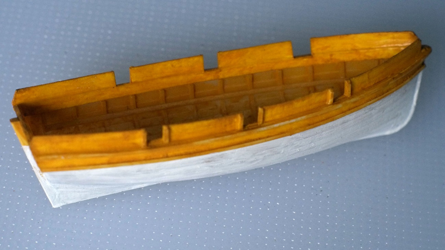
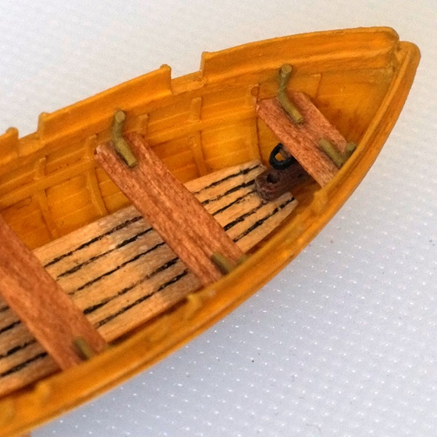
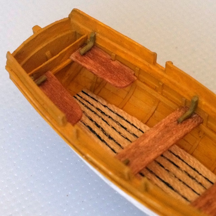
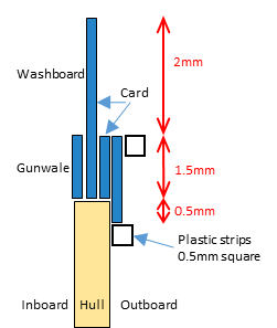
The boat is taking shape now. I built up the sides with card and polystyrene strips. This gives me a gunwale, wash boards and tholes. I also extended the transom and added a stern post. (The card is yellow because I happened to have a piece that is 0.2mm thick.) After this construction step I gave the boat her first coat of paint. The outer face will need more coats later including black detailing of the wales. The inside gets its details next. The floor is from a piece of obechi, 0.5mm thick, with the lines between the planks drawn in. I also fitted the thwarts and stern seats, all cut from the 4x0.5mm planks supplied in the kit for decking that I stained a patchy brown. The knees between the thwarts and hull are from copper wire painted brown. The thwart in the bow and the floor have fittings to hold the mast. My current task, slightly out of sequence, is to make the cradles to hold the boat on Whiting's deck. There will be a lot of handling of the boat while I trim the cradle to fit and I want to get this done before I start on the delicate bits. Happy Trafalgar day for tomorrow! I am going to a dinner organised by the 1805 club. George
-
Tony, I imagine that the rudders could be stowed in the boats or hung from their pintles when the boats are on deck. If the boats are nested then the rudders on the smaller boats could get in the way and risk damage so they might be put inside the hull. The bigger issue is probably to ensure that the rudders are secure and will not be damaged or swept away when a wave breaks over the ship. I suspect that they are safer inside than flapping on the outside so long as they are tied down. On a similar note, the restored boats often show the oars tidily arranged on the thwarts. Surely they would be tied on to the thwarts when stowed and the tidy arrangement then becomes a bundle. George
-
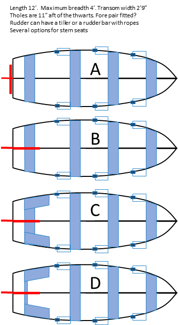
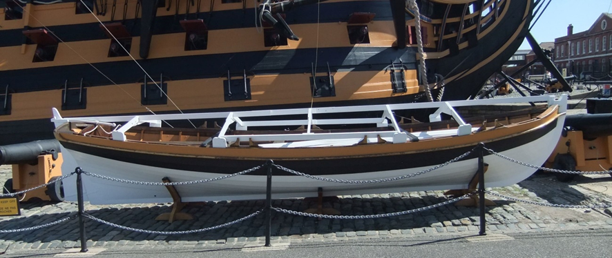
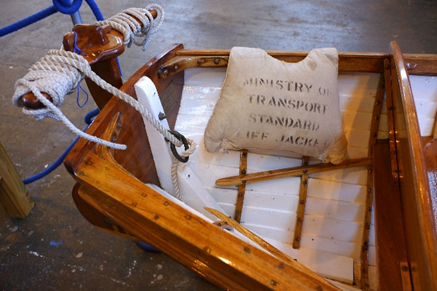
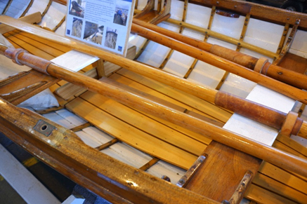
Building a boat from a decent kit should be a simple job but a little research leads to a lot of research that raises more questions. I have not found Admiralty drawings for a 12 foot cutter and relied on drawings of larger boats, photographs of restored examples, and information from sailors. ‘The Boats of Men of War’ by WE May is a classic and a web page by David Manthey summarises part of it https://www.thebigrow.com/?p=1043 . I have accepted the shape of the hull as supplied in the kit but there are a lot of other features where judgment is needed. Single banked or double banked. A double banked boat has two oarsmen on each seat and this is far too wide for Whiting. In a single banked boat there is one oarsman per seat and he usually has one oar. A cutter that I photographed at Portsmouth in 2011 has six thwarts with thole pins, alternating port and starboard like on a racing eight. When there are only two or three oarsmen it is likely that they have a pair of oars each which makes it easier to balance the thrust by sculling. I assume that Whiting’s cutter has two oars for each oarsman, and this is seen on a recently restored gig at Portsmouth Historic Dockyard. Thwarts. The Vanguard hull has an internal, horizontal rail and the thwarts rest on them. The width of the thwarts varies and I chose 9 inches as a compromise between comfort and space. The pitch from thwart to thwart (=gap + width) is between 2’3” and 3’0”. The hull is long enough for three thwarts for oarsmen and one in the stern for someone to steer. However, the oarsman in the bow sits in a narrower area and has poor leverage on the oars, so it is possible that there are only two oarsmen. The Portsmouth gig has three thwarts (plus one in the stern) but the one in the bow does not have rowlocks. I decided on three thwarts for Whiting’s boat, all with oars, though I might yet provide oars for just two. Stern seat. Most boats with a wide transom have a seat (stern sheets) that runs across the stern and forward from it along the sides of the hull. Some add another cross-wise thwart at the fore end of the seats on the sides. Others dispense with the seats that run across and only have two along the sides. The Portsmouth gig just has a thwart with a back rest. I am not sure yet what to do here. Gunwale and washboards and wale. The top edge of the hull on the Vanguard kit looks low to me, both for water splashing over it and for the oarsmen banging the oars into their knees. The vertical separation between a thwart and an oar was between 6 and 10 inches. The kit hull also tops with a clinker plank and there is no sign of a gunwale. I will build up a gunwale to add an extra millimetre or two in height, and a wale (rubbing strake?) below it. Washboards above the gunwale are also wanted, about 2mm high. Rowlocks or tholes. These provide a fulcrum for the oar and both were in use at the time. The rowlock is a metal ‘U’ on a pin that would swivel. Tholes were wood pins fixed into the gunwale and they also supported adjoining sections of washboard. I will use tholes on my model. Rudder. The rudder itself hangs on two pintles. Most depictions show them with a tiller that comes in over the stern of the boat, but this is difficult to use on a narrow boat. Some boats such as the Portsmouth gig and modern racing eights replace the tiller with a bar that runs from side to side and has ropes tied to its ends. The rudder is controlled by pulling on the ropes. The choice here ties in with that for the stern seat. Floor. The floor of the Portsmouth gig is made from six tapered planks and has raised boards for the oarsman to brace their feet when pulling. Larger boats have a grating below the stern seats and another forward. My model just has the tapered planks. Mast and sail. Boats carried a mast or two and sails. My guess is that a small cutter would have a mast well forward and hang a simple sprit sail from it. The boat is stowed aboard on my model so I do not need to worry much about the detail of the sail. I guess that the sail was wrapped around the mast with the yard bundled into it, and then the whole assembly would be tied in place on the thwarts. The thwart in the bow would have an extension to support the mast, and I will put a block of wood with a hole in it on the floor to step the mast. (A lug sail is also possible and the mast could then be set further aft next to the second thwart.) Oars and grapnel. These were stored on the boat, tied to the thwarts. Mine are based on etched brass items from Caldercraft. Here are a few sketches of the options I am considering. The current front runners are C and D though I reserve the right to change my mind after hearing sound advice and opinions from the good people at MSW. A selection of photos from Portsmouth dockyard that I found useful. Victory’s boat in Portsmouth, 2011. Six tholes, alternating port and starboard Restored gig in Portsmouth, 2023. Rudder bar with ropes, pairs of holes for rowlocks, floor George
-
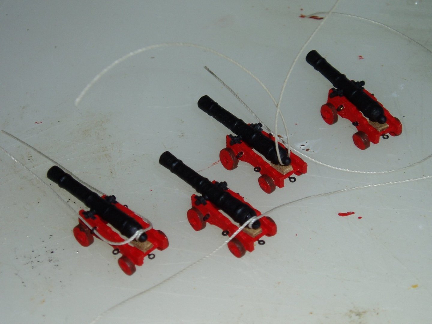
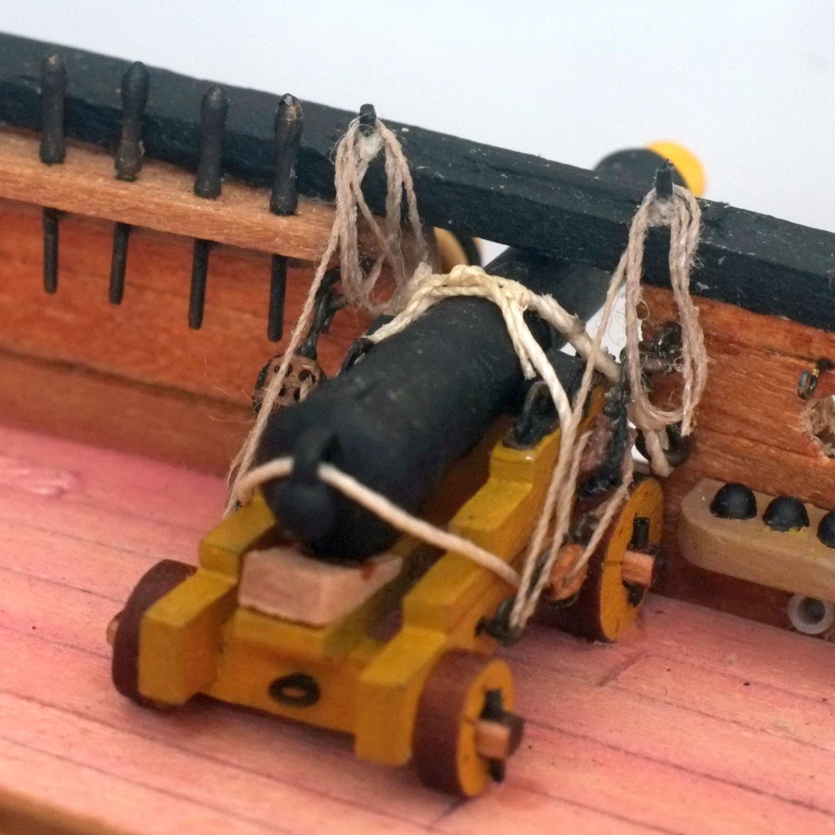
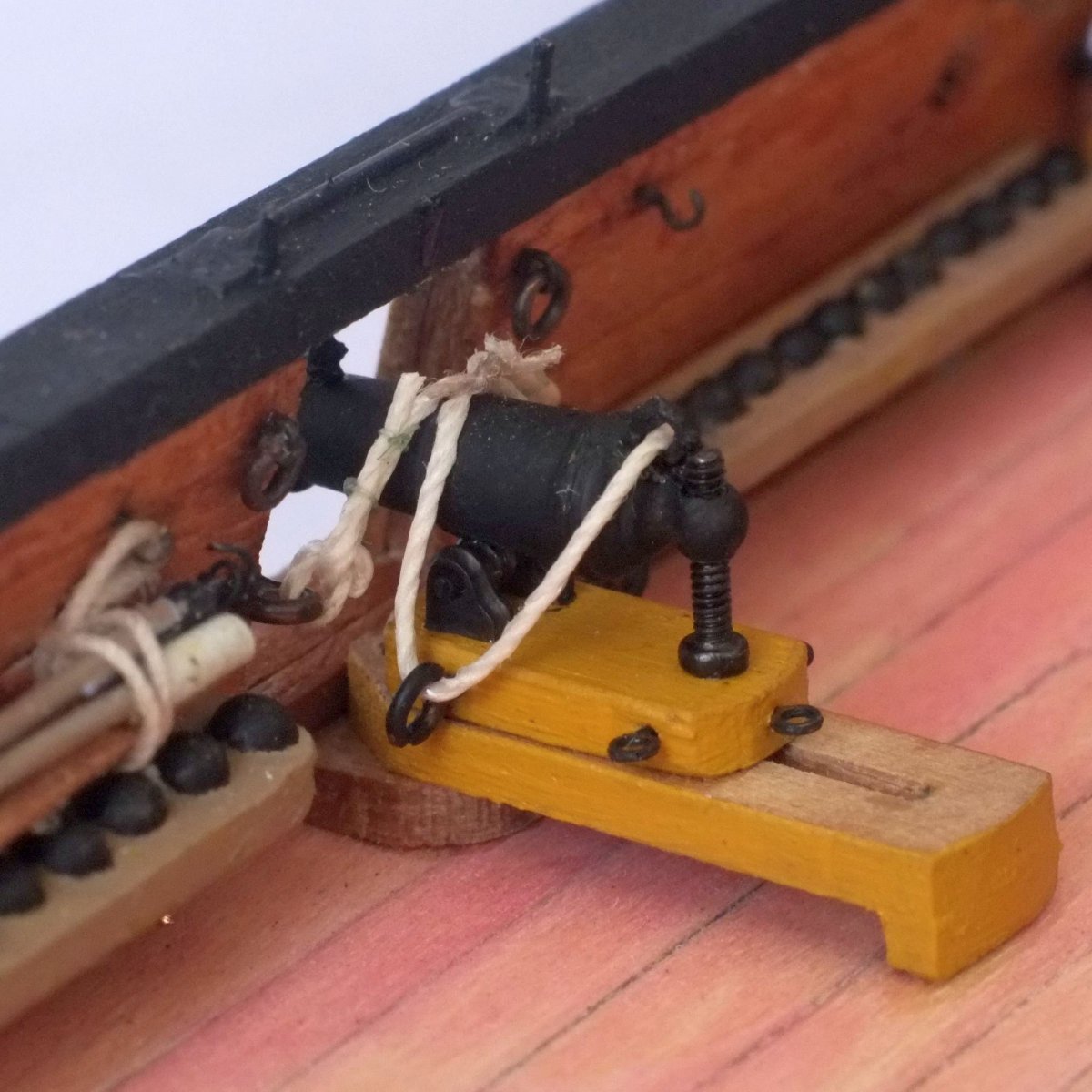
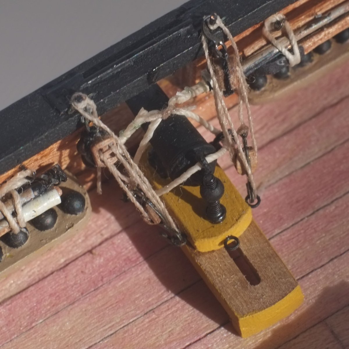
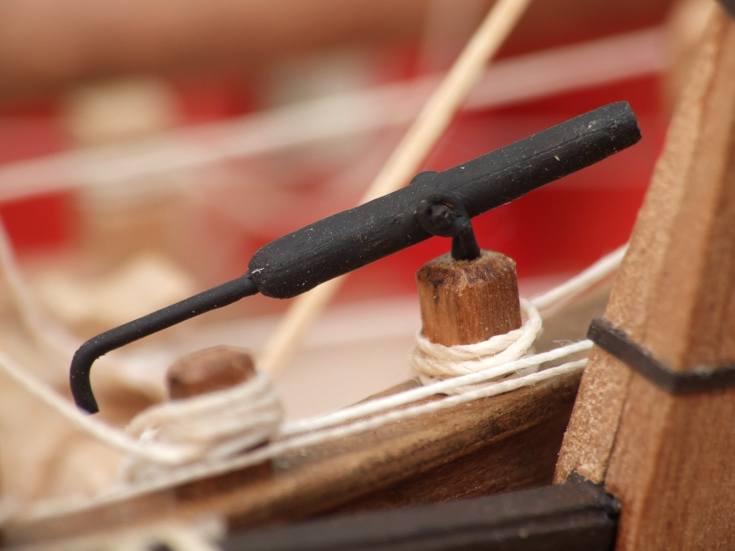
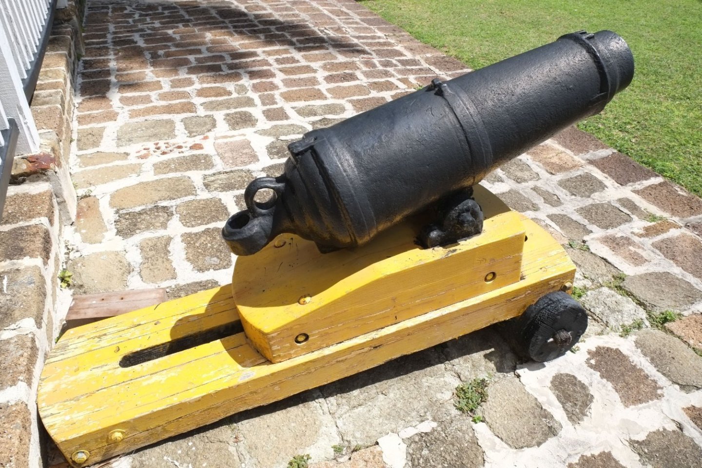
Back home after a long break and with time set aside for modelling I want to get the hull finished by next spring. The two cannons on Whiting are now in position. I fitted simple pegs in the gunwale above the gun ports and tied the falls from the gun runout tackles to them, before making a few simple loops and hanging them over the pegs. The Gutermann thread I used for the tackles is not keen to absorb PVA glue and the ropes are scruffier than I like. It's obvious in the enlarged photos but not a problem at normal viewing distances. The training tackles from the rear of the carriage to the deck are stored 'below' on my model. I doubt if they were left in place because they would be a serious trip hazard on a narrow and crowded deck. I may yet add them, possibly hooking them over one of the pegs on the gunwale. Carronades The carronades in the Ballahou kit are horrible and their only use is to melt them down to use as weights. I bought a pair of Caldercraft brass carronades with their mounts and they are good. A few minor changes: I replaced the eyes for the breeching rope with 'hinged eyes' that can swivel and change direction. I replaced the brass rod for the elevating screw with real screws which look much better. A pack of 50 from Ebay is cheap: look for M1x5mm Philips pan head micro screws with a black finish. I glued an eye over the cascabel to guide the breeching rope in the same way as on Blomefield cannons. A fore sight made from scrap etched brass and a tompion (a slice of cocktail stick painted yellow) finish the firing end. The breeching rope was lashed in position is the same way as with the cannons. The runout tackles made with 2mm blocks are too bulky to fit on the model because there is simply not enough room between the eyes on the bulwarks and the eyes on the bed. I hooked the tackles over the pegs on top of the gunwale and then tied the falls to the pegs leaving just a short length dangling down. The crew will have to reposition them when they go into action... (I notice on the enlarged photo that the double block looks like it is 90 degrees twisted. It's too late to change it now.) Carronade in Nelson's Harbour, Antigua on a modern mount. It's missing the elevating screw and the fore sight Boat The next job is to make a boat and its cradle. I have a 12 foot cutter from Vanguard Models and photos of a recently restored gig at Portsmouth Museum and am currently planning how to add a gunwale and wash strakes and all the internal fittings. George


-
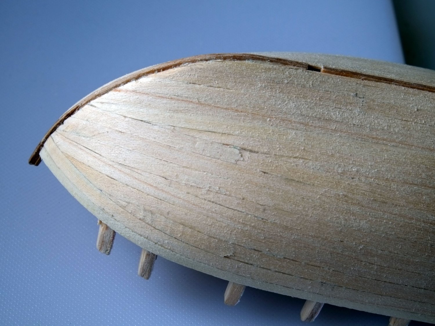
If it's not too late to add to this thread... When I have a plank that sits too low, usually where it takes a short cut between two bulkheads, I cut a short length of the same plank material and glue it onto the one that dips. The width of the plank is often a perfect fit though sometimes it needs a taper. The first photo below shows where I went wrong in a few places at the bow of Whiting. I glued on the strips, sanded them, and then sanded the whole hull. Second picture is after sanding and the ends of the patches can be seen. George

-
Phil, That's a lot of preparation and sanding to achieve some splendid wooden hoops. I used a similar technique but with paper instead of wood shavings. It's quicker but the hoops are made of processed wood (paper) and not proper wood. I printed dotted lines on a sheet of cream coloured paper; the spacing between the lines is the width of the hoops. The mandrel is a length of mast dowel with a few layers of foil wrapped around it. The foil increases the diameter so that the hoops can slide on the mast and is a barrier to prevent them from gluing to the mandrel. Guess how many turns of paper you will need to get the thickness you want and cut a rectangle from your sheet. Wrap the paper around the mandrel and glue the layers together with PVA. When the glue has set the individual hoops can be cut off by running a knife blade over a dotted line while the paper tube is still on the mandrel. The cut edges do not need much tidying or trimming. That's it. The remains of the printed dots even add to the effect of wooden hoops. The photos below are from my Sherbourne. George
-
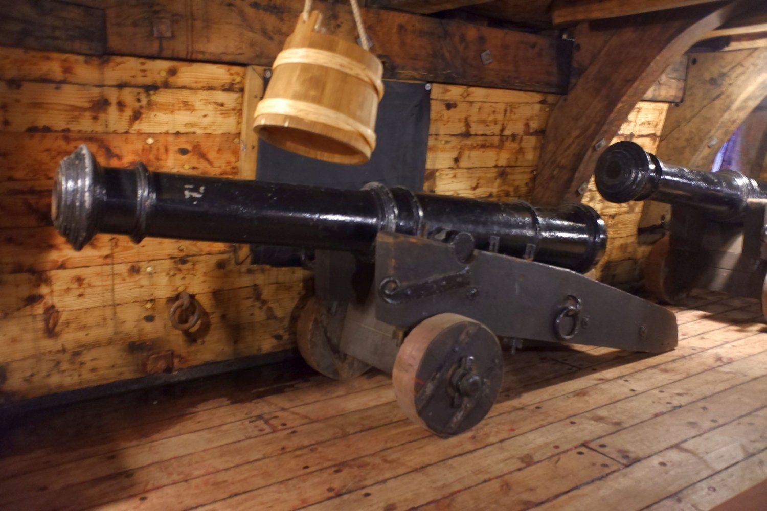
I visited the Golden Hinde replica in London last month (birthday treat for 6 year old grandson) and have this photo of one of the cannon. The carriage is a 'tail dragger' to use an aviation term. Clearly this is not a restored original but a 1:1 scale model so it is not necessarily correct in all respects. All the carriages on board were to this design. I recall seeing similar carriages on the Mary Rose at Portsmouth but do not have photos. Perhaps someone else has one to share? Mary Rose is earlier than 'early 17th century' in the original post but she could give a strong indication. George

-
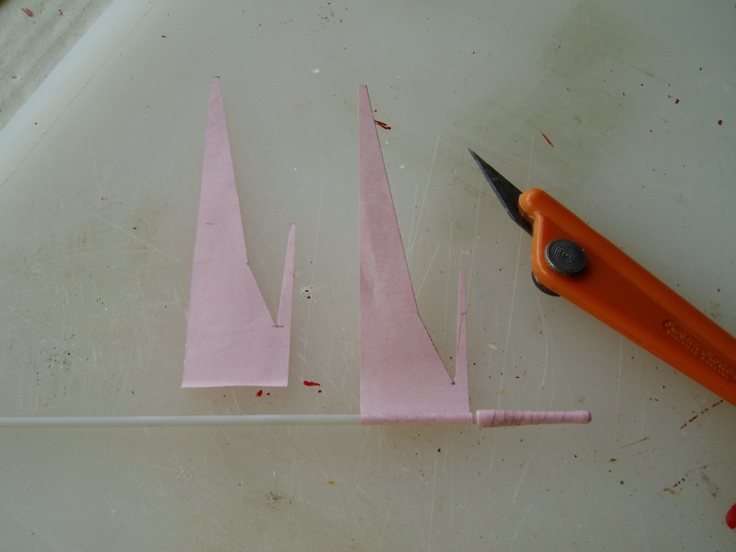
Benjamin's carronades look good and the black paper makes it easy to get the colour right. I used this technique on Sherbourne many years ago to make 3lb cannons but with pink paper. The choice of colour was set by wanting to use the thinnest paper that I had available so that the steps in the rolling process would be small. The photo shows the build sequence with tapered pieces of paper. The spike at the muzzle end is for the greater diameter at the muzzle. I also made swivels that are a lot slimmer than the kit parts. Tony (tkay11) mentions my book about Sherbourne where I describe this technique. (Thanks Tony). There is a pdf of the relevant chapter on another thread https://modelshipworld.com/topic/4335-super-detailing-the-cutter-sherbourne-by-george-bandurek/?do=findComment&comment=124292 or you can download it here Cannon.pdf. A big advantage of wrapping paper around a tube is that the cost is very low but it does take time to make a barrel. George