georgeband
-
Posts
304 -
Joined
-
Last visited
Content Type
Profiles
Forums
Gallery
Events
Everything posted by georgeband
-
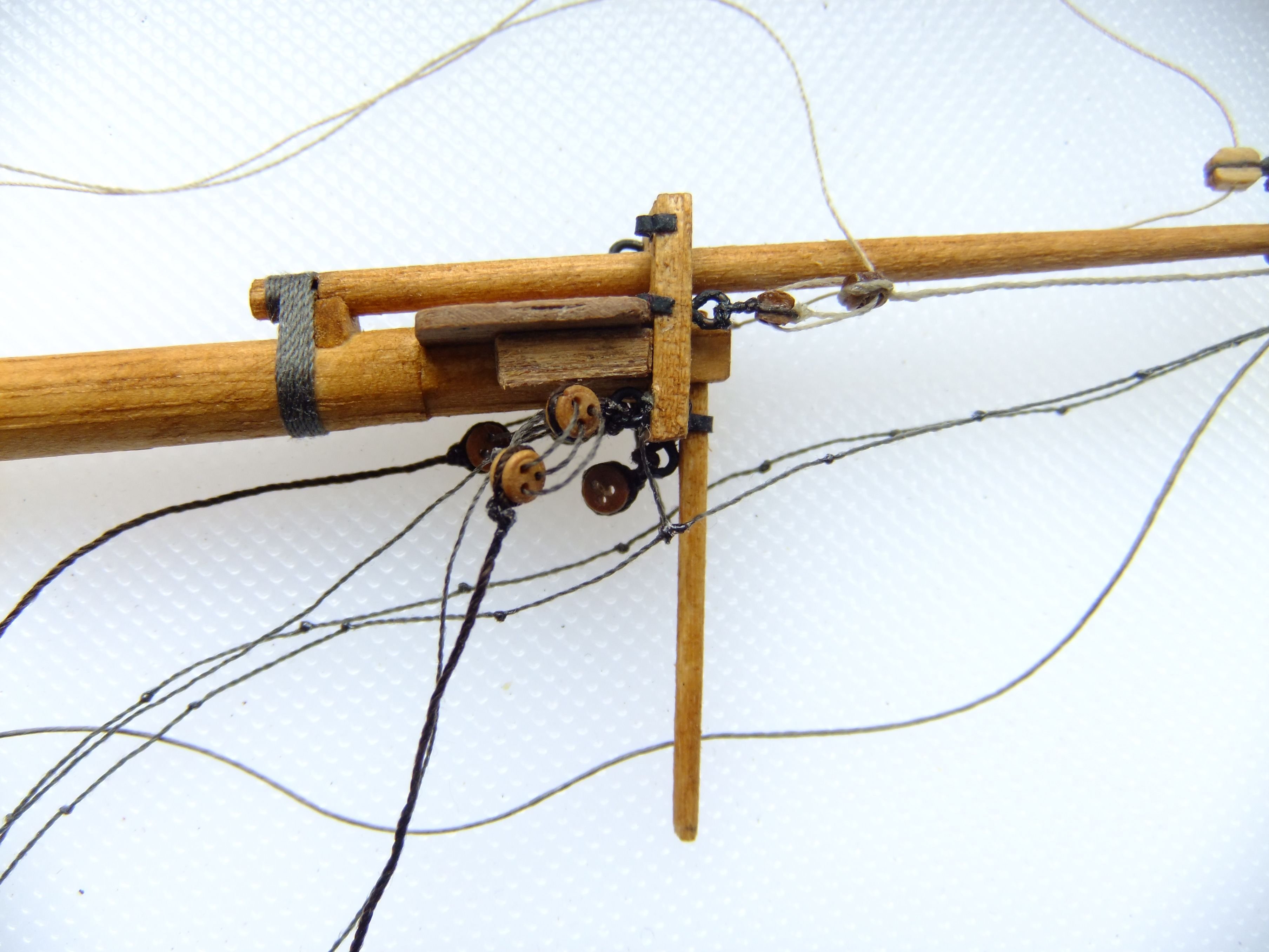
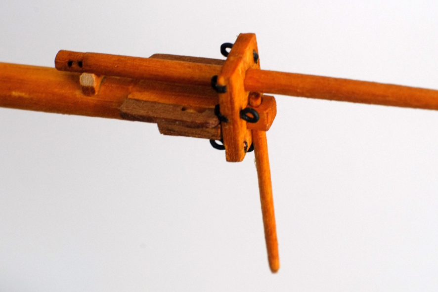
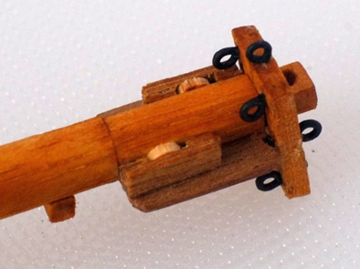
 Back after a long break from model making. Grandchildren take priority because you only get one chance to see them growing and if you miss it then it has gone. A model ship can wait. I have spent the last few weeks refreshing my memory about what I had built and what was coming next. I discovered that I had overhauled my supply of blocks and have plenty of 3D printed ones from Seahorse and a lot of redundant wooden blocks. I have expanded my stock of rope with Gutermann threads from a local shop; diameters from 0.2mm to 0.4mm in shades of brown and tan are readily available and cheap. The lay of the strands is a bit looser than the tight rope from Ropes of Scale but at normal viewing distances they are not visible. I have ordered thicker ropes (0.45 tan and 0.6 dark brown) from Ropes of Scale. The bowsprit and jibboom were assembled when I downed tools in May. I have now tied on most of the rigging and am preparing to mount this spar to the hull. The photo below shows the ropes that are connected to the jibboom. From the top they are the inhauler, outhauler, horses and stirrups, and martingale. The rope that ties the heel of the jibboom to the bowsprit is also visible. All of these ropes are Gutermann threads. The next photo shows ropes connected to the bowsprit cap. Two bowsprit shrouds are attached with 2.5mm deadeyes. There is one deadeye ready for the bobstay but I am waiting for a delivery from Ropes of Scale before I can finish this. I used deadeyes here rather than hearts because I think they look neater and it is quite possible that they were used on Whiting. George
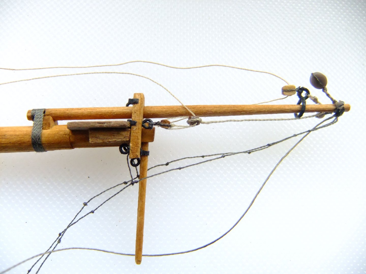

-
I am sure that similar problems occurred in reality while a new lieutenant was desperately leafing through his copy of Lever's 'Young officers sheet anchor' to find the right page. George
-
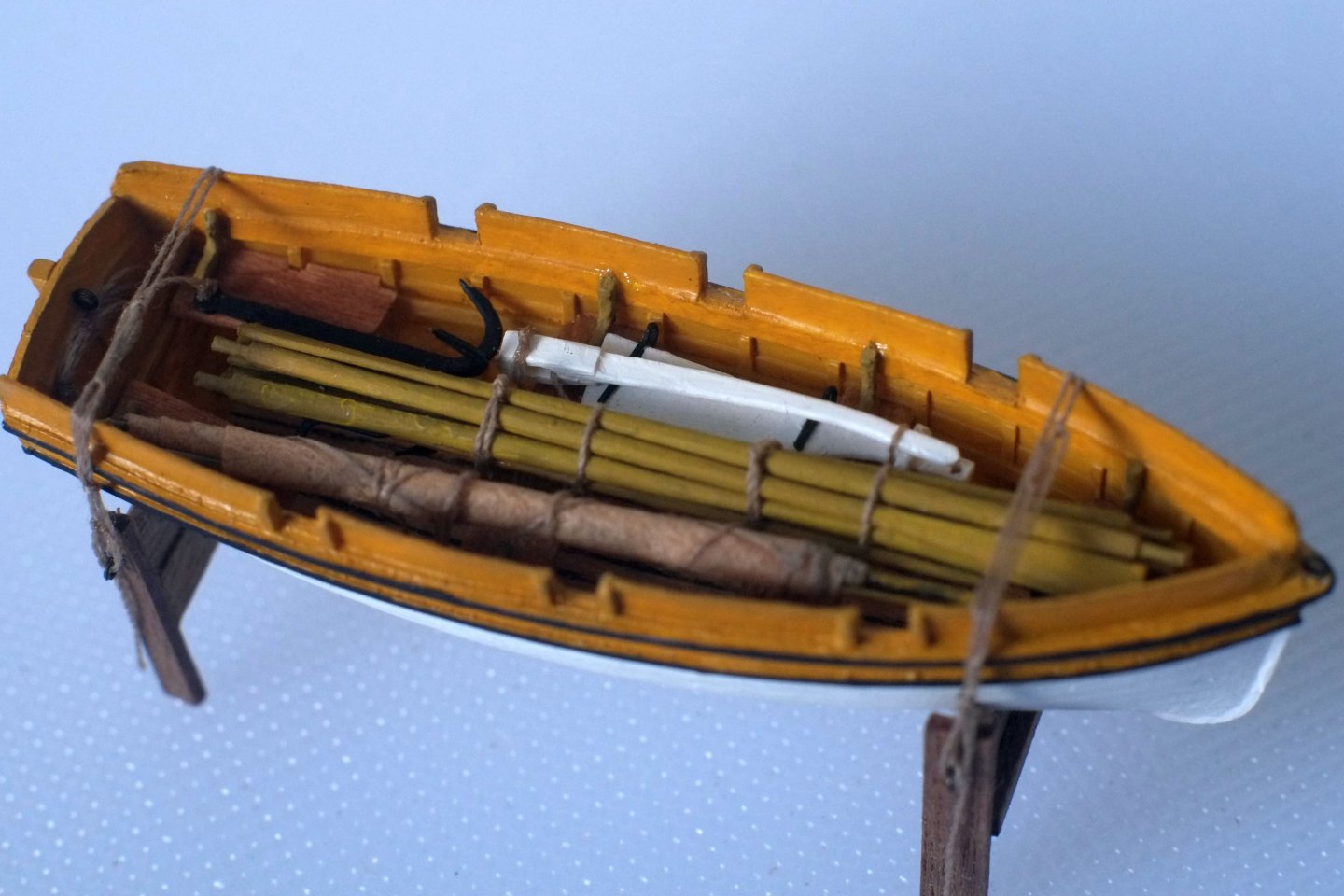
My schooner model has one small boat on deck and that is all that she carried. I filled the boat with oars and spars and a sail and grapnel and boathooks and the rudder and tiller and all are tied down to the thwarts so they will not get swept away by a high wave. I chose this look because it adds to the clutter and crowding on deck and in the absence of contemporary information the aesthetic took precedence for me. As with so many aspects of our hobby, do what looks good to your eye if you cannot find a proper answer. George
-
Blocks: wood, card or 3D resin?
georgeband replied to georgeband's topic in Masting, rigging and sails
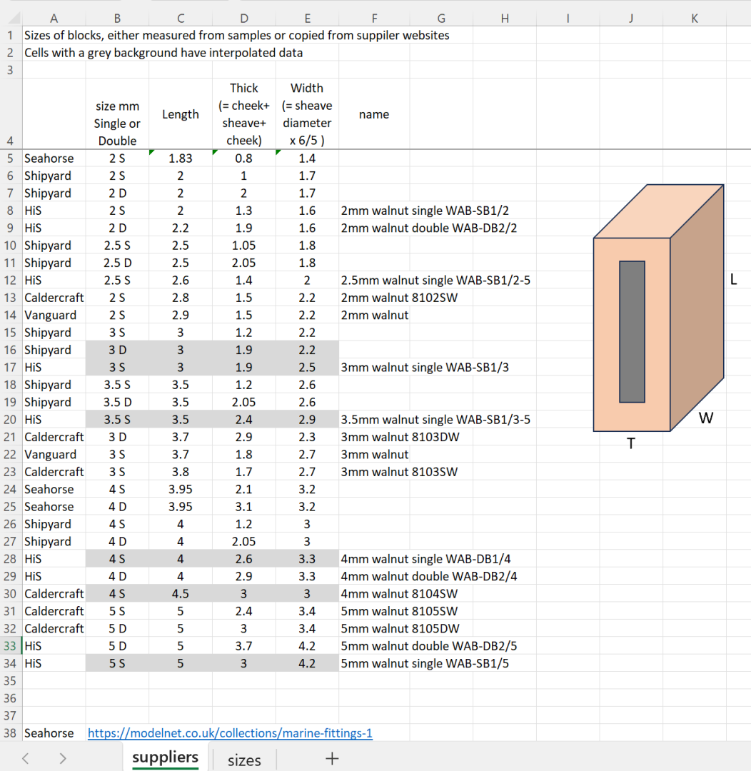
I have measured the other 3D printed blocks from Seahorse that I have. I used a vernier gauge with a resolution of 0.05mm and repeated my measurements up to four times to check for consistency - it is tricky to align the blocks with the jaws of the gauge. My results for the 2mm single blocks (2.00mm long, 1.00mm thick, 1.55mm wide) are larger than what Tony measured so I checked that my gauge shows zero with the jaws closed. It does, so either the parts are different or it is from our measurement methods, but this is not an ISO9000 audit so I shall let it rest. Here are my results. The Seahorse blocks are highlighted. The revised spreadsheet follows. blocks.xlsx George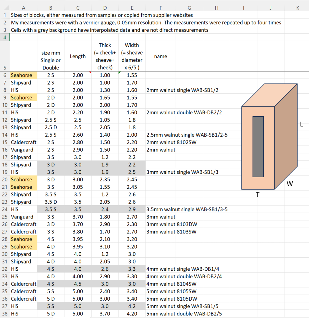
-
Blocks: wood, card or 3D resin?
georgeband replied to georgeband's topic in Masting, rigging and sails
I shall get onto it at the end of the week, Tony. George -
Blocks: wood, card or 3D resin?
georgeband replied to georgeband's topic in Masting, rigging and sails
I have expanded the spreadsheet to include the measurements of Seahorse blocks that Tony and I have made. blocks.xlsx The tab labelled 'sizes' is based on information from Steel's treatise on blockmaking. You can find the original here https://maritime.org/doc/steel/part5.php and it is a bit convoluted. The spreadsheet version looks like this Further down this page in the spreadsheet is information from Steel about the rope sizes for strapping the blocks. Again, it is a bit convoluted and also throws in a couple of inconsistent results for 11" and 12" blocks. I have assumed that Steel's rope sizes are for the circumference of the rope; the model sizes I worked out are for the diameters. The other tab in the spreadsheet 'suppliers' shows the dimensions of blocks from various suppliers. Some such as Shipyard are from the manufacturer's website. Most of the others are from actual measurements (thank you Tony for filling a gap for the smallest blocks). The values with a grey background are my interpolated estimates based on results for other blocks from that supplier. Gregory, We all do what looks right to us and sometimes try to to justify it. The rambling discourse that follows is my justification... I agree that it is possible to become too much of a purist when it comes to scale accuracy. I think that the attitude can be summarised as 'If it is more detailed than what I do then it is over the top, if it is less detailed than what I do then it is sloppy'. We all find our level and accept that it is different for different people. For block and rope sizes I am guided by Steel's writing because I have not found another contemporary source and, vitally, I do not have experience of full size ships apart from HMS Victory. And in the case of Victory the blocks might have been replaced in the last 200 years, possibly using what was available at the time from naval stores in Portsmouth. For my model of Whiting I am using three sizes of blocks (2mm, 3mm, 4mm from Seahorse) in all places except one where I have a 5mm block which is a cleaned up Caldercraft example. (The cannon and carronade tackles use HiS 2mm blocks because that is what I had a couple of years ago.) I don't like the look of 'big blocks' which look too heavy to my inexperienced and distorted eye and tend towards choosing smaller sizes. The 8.8 ratio gives a minimum size for a block to go with a given rope, though the rope size itself is another matter and involves its own judgment. George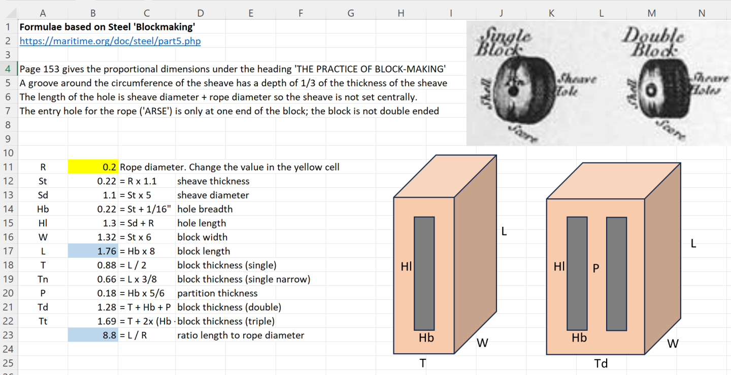

-
Blocks: wood, card or 3D resin?
georgeband replied to georgeband's topic in Masting, rigging and sails
Applying Steel's convoluted information about proportions of blocks (see the spreadsheet a few posts up) the length of the block is 8.8 times the diameter of the rope. This would be the maximum diameter of rope so Tony's 12x formula is quite plausible. Using the spreadsheet, I find that a block that is 1.83mm long is designed for a rope that is 0.208mm diameter. It would also work with 0.15mm rope 🙂. Does anyone have an alternative to Steel's proportions? George -
Blocks: wood, card or 3D resin?
georgeband replied to georgeband's topic in Masting, rigging and sails
'Visible layers...' It took a lot of effort to photograph the blocks with enough magnification to reveal the layers. My eyes with spectacles and a magnifying glass could not see them and at a 30cm / 1 foot viewing distance with naked eye the layers are irrelevant. Tomasz, save your money, the resolution on your existing printer is quite good enough for this model maker. What I would like for the future is some 3D printed cleats, especially shroud cleats which are difficult to fashion from wood. George -
Blocks: wood, card or 3D resin?
georgeband replied to georgeband's topic in Masting, rigging and sails
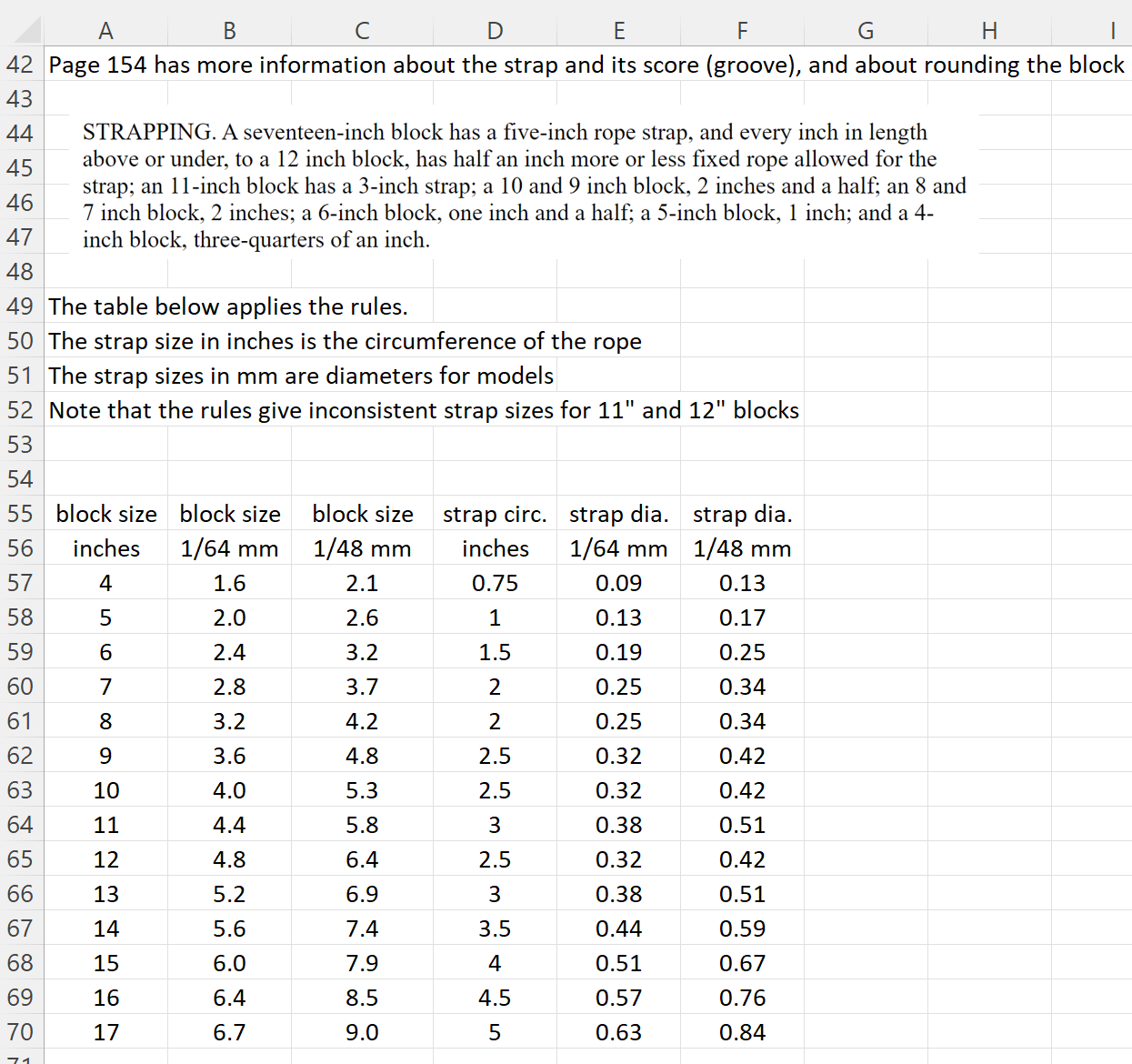
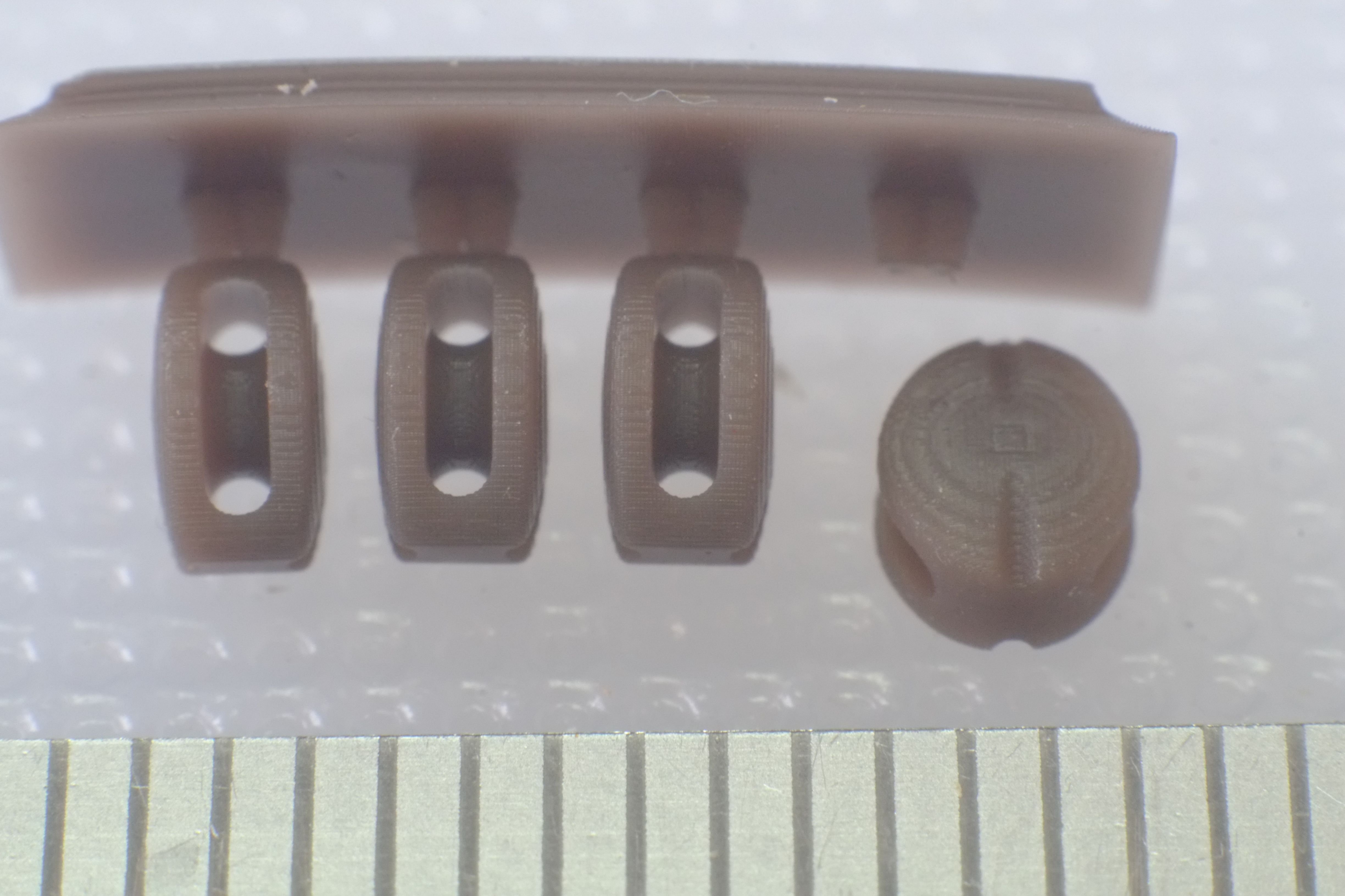
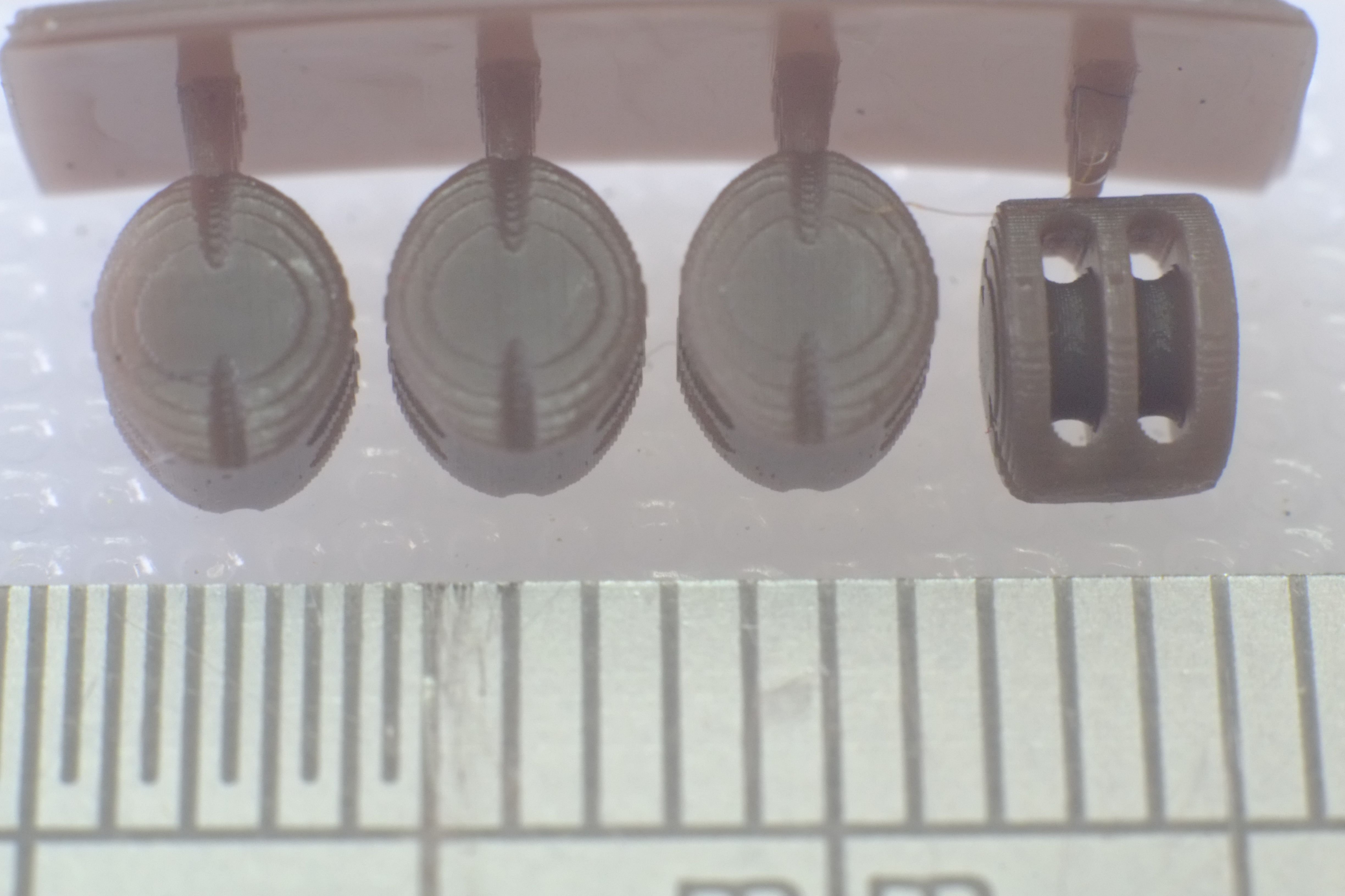
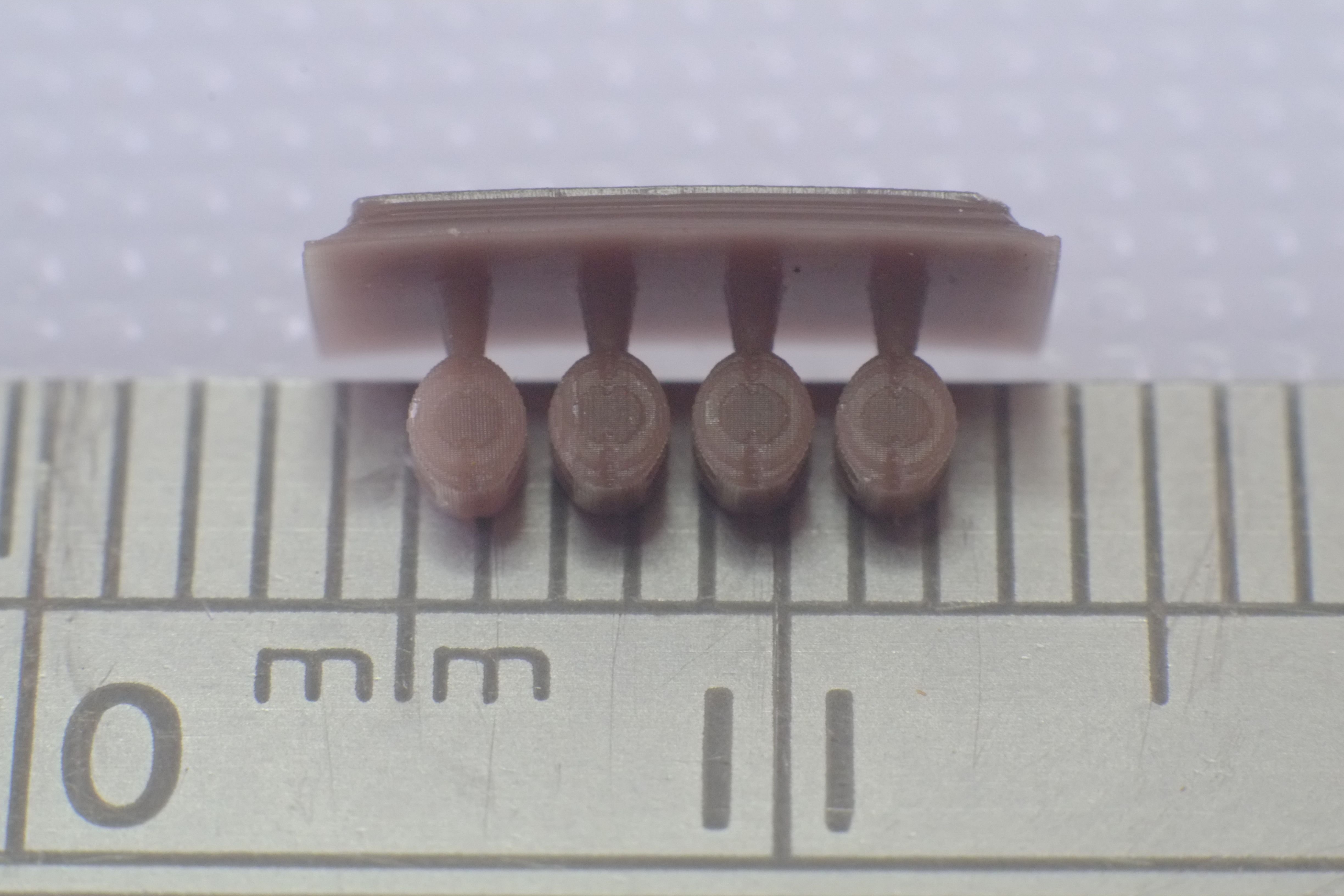
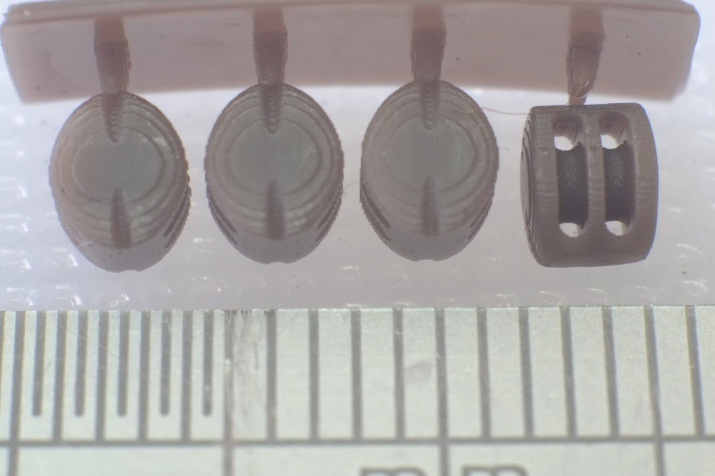
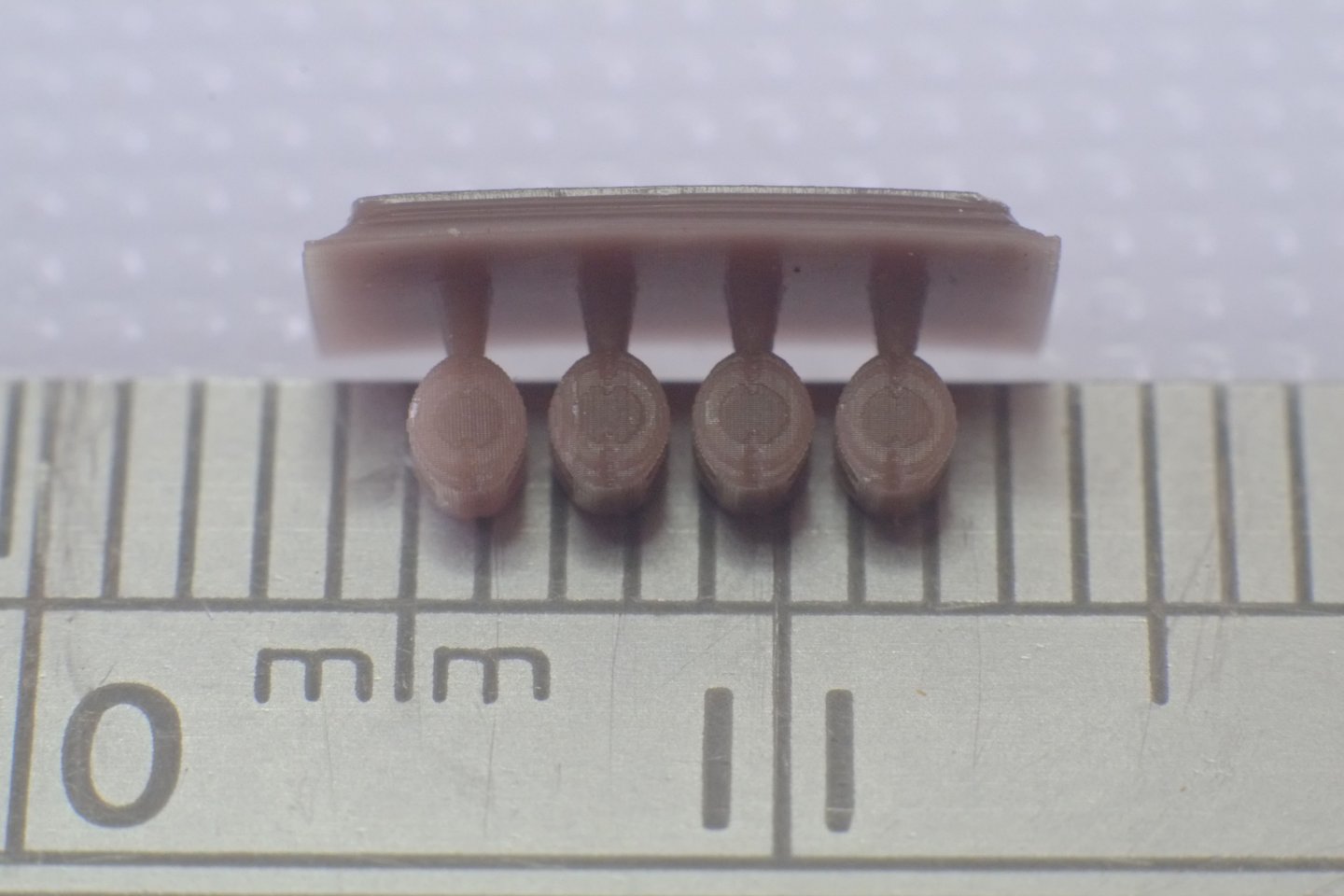
I have to commend Modelnet for rapid delivery of some Seahorse 3D printed blocks. I had not realised that they also ship from UK so my small package only had to contend with Royal Mail. The blocks themselves are finely printed and do not have any translucency that others have mentioned. The photos below are of 4mm double and single blocks, and 2mm single blocks. You can see the layers from the 3D printing with this level of magnification, but it is finer than the roughness on walnut blocks. One downside of these blocks is that the sheaves are too small in diameter and the holes for the rope should be much smaller at one end of the block; the blocks are not double ended. Overall I am very impressed and these blocks will be my choice in future. Does anyone want some Caldercraft wooden blocks? The proportions of the Seahorse blocks are close to what Steel outlines in his descriptions of block making. The CNC blocks from HiS are also well proportioned but the roughness of the wood does show up on close inspection. The card blocks from Shipyard are much too thin (cheek+sheave+cheek) and do not look right alongside the others. The spreadsheet below shows the dimensions of blocks and their ropes as described by Steel. A second tab lists the dimensions of blocks from different suppliers. I hope this helps with your decisions. blocks.xlsx George
-
Blocks: wood, card or 3D resin?
georgeband replied to georgeband's topic in Masting, rigging and sails
I have placed an order with Modelnet for 2mm, 3mm and 4mm blocks. As Gregory says, their pricing is competitive and their shipping charges are also very reasonable. Once I have them I will try some macro photography to compare them with HiS blocks that I have. George -
Blocks: wood, card or 3D resin?
georgeband replied to georgeband's topic in Masting, rigging and sails
Tony and GrandpaPhil, Here is another link for Seahorse 3D printed blocks. It's a model shop in Poland though I have not used it yet. https://modelnet.co.uk/collections/marine-fittings-1 . There is a filter option for '3D' which selects the Seahorse parts. You can also find them on Ebay if you search for 'seahorse block 3D'. Wefalck, I agree entirely that the blocks should have a family resemblance and mixing the cheap, kit blocks with the finer examples is visually distracting. This is more obvious for the larger blocks where the shapes are easier to see at normal viewing distances but less of an issue for a 2mm block which is a 'blob' unless you get really close. What I don't know is whether blocks from HiS, Shipyard or Seahorse look OK next to each other. I might just have to buy some of each and see which I prefer. George -
I have been working on the rigging plan for HMS Whiting schooner and now know how many blocks I want of various sizes. The small ones are especially tricky, partly because there are so many of them. Block Need for model 2mm S 3 2.5mm S 48 2.5mm D 7 3mm S 26 3mm D 7 4mm S 10 4mm D 13 5mm S 1 I have already used 2mm walnut blocks from HiS for the gun tackles and they are at the lower limit of what is available. The next size up, 2.5mm from HiS, matches the cheaper '2mm single' blocks from Caldercraft and other suppliers. I am happy to use either of these because the imperfections are not visible at normal viewing distances. Whiting (in my rigging plan) also needs seven double blocks of this size. I see four options here. I could get the blocks from HiS (2.5mm double). Advantages are no assembly or trimming and a known shape and material - walnut. Disadvantage is cost including shipping. I could sand down some '2mm single' blocks from Caldercraft and glue them together in pairs to make double blocks. Advantages are the material and size which matches the single blocks. Disadvantage is some careful sanding and gluing. Shipyard provide laser cut card layers that the modeller laminates together. Advantages are the shape and finish, although this might not be visible for a 2.5mm block. If it is visible and better then I would want to replace the single blocks I have with card. Disadvantage is that assembly of the layers might be difficult. Seahorse offer 3D printed blocks in brown resin that according to them 'do not need painting'. Advantages are no assembly and little trimming. Disadvantages are an unknown material which could look different from wood blocks in which case I would have to replace the single blocks. For the many 3mm single and double blocks the Caldercraft parts are probably adequate in isolation though they might show up badly against the alternatives. This is certainly the case for 4mm and 5mm blocks where the HiS parts look like proper blocks while the Caldercraft ones look like roughly shaped pieces of walnut. Should I choose HiS walnut, Shipyard card, or Seahorse 3D printed for 3, 4 and 5mm blocks? Has anyone else travelled this way and can offer their experience? George
-
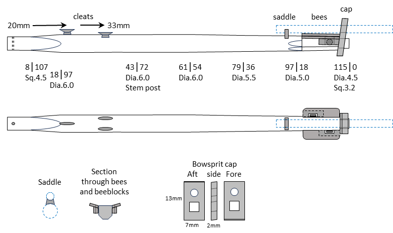
Allan, Here's a link to Phil's spreadsheet. Use it wisely. I, perhaps unwisely, have modified it for my own purposes and had to guess some sizes for ropes which Lees has not included. I forgot yesterday to include the drawing of the jibboom that I used for Whiting. It might be useful for a Ballahou builder so here it is. George

-
It has taken a while and I have completed the woodwork for the bowsprit, cap, jibboom and martingale. The drawings I prepared needed a few tweaks along the way when reality intervened and I have spent an age defining the rigging plan. According to my log this stage of the build took 18 hours though the drawings themselves took about twice that time. This is the finished article and I will not bore you with all the construction details. Here is the tip of the bowsprit from below to show the bees and bee blocks. My current task is to expand the rigging diagram to include the sizes of ropes. I have modified a spreadsheet table that Phil (Dr PR) originally set up using information from Lees. Lees' scaling rules give a wide range of sizes with some very small differences between them and I am resorting to rounding the figures for three reasons: I cannot believe that a vessel with limited storage space would keep sizes equivalent to model diameters of 0.20 0.21 0.23 0.24 0.25 0.26 0.27mm. (What happened to 0.22mm?) The visual difference between these sizes is too small to see Other tables such as zu Mondfeld give quite different answers. As with the spars and sails, the rope sizes are judgement calls. At this time I think I will probably have ropes that go up in steps of 0.1mm diameter, possibly with an extra for 0.25mm. What do others choose in this situation? George
-
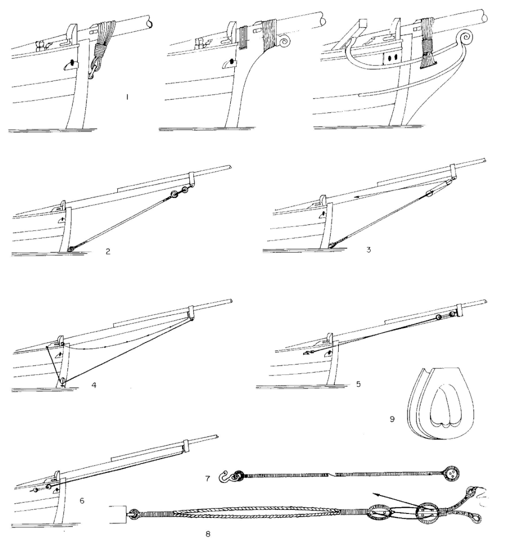
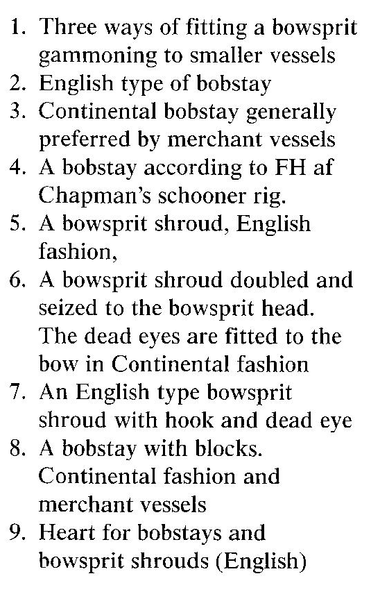
George, I have scanned the relevant page from Marquardt and here is a crop which shows three alternatives for holding the bowsprit to the hull. The author gives precious little guidance about which was used when or where and I did not see anything which suggests that the choice of method depends on the length of the bowsprit. The other illustrations on the same page show variations for bobstays and shrouds. This is the key to the pictures (which I cannot make smaller here...) I hope that some of this helps. George
-
George, The book I usually refer to during my build of a schooner is Marquardt's 'The Global Schooner'. On page 169 he shows three alternatives for gammoning and the simplest is one that uses an (iron) ring in the stem, below the bowsprit. He also shows variations of shrouds and bobstays to support the tip of the bowsprit. Let me know if you want to see the relevant page and I will scan it for you. Best regards, George (another one)
-
It's my pleasure to help, Colin. Transcribing log books and other documents is an absorbing hobby and I vaguely remember when I first understood Do.Wr. It was when a log book had 'Do.Weather' for one day after a sequence of 'Do.Wr.' and the penny dropped for me. George
-
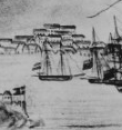
Martes, Here are a couple of pictures from USN archives. The first is St Thomas in the Virgin Isles in 1823 which shows a lot of ships and other vessels in harbour. At the left of the pack is what looks like a schooner with no yards on her masts; they might have been lowered to deck level but their absence in the drawing is certain. https://www.history.navy.mil/our-collections/photography/numerical-list-of-images/nhhc-series/nh-series/USN-901000/USN-901913.html This is a crop of the area of interest. Here is another, similar picture of Laguira (Venezuela) which unfortunately is not dated. This time there is a schooner just to the right of the centre of the pack which is described as a 'Dutch merchant schooner'. As with the picture above she has two tall masts and no apparent yards. https://www.history.navy.mil/our-collections/photography/numerical-list-of-images/nhhc-series/nh-series/USN-901000/USN-901914.html Neither of these pictures has positive confirmation of triangular sails though the absence of yards does suggest that they could be examples of Bermudan rig. Good hunting for more pictures! George
-
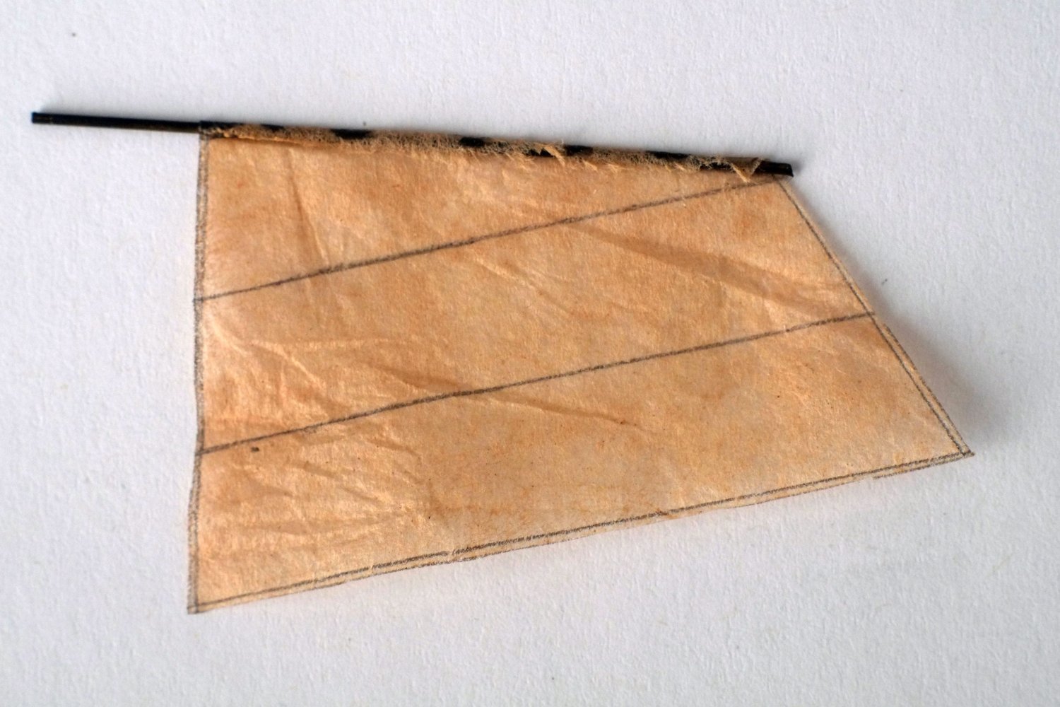
I have used teabag paper to make a sail for a 1/64 boat. The paper was reclaimed from a used teabag and therefore has sound environmental credentials, but the size is limited. The photo shows a tea-stained sail glued to a wire mast; the seams are drawn on with pencil. A quick search on the web for 'tea bag paper' shows several suppliers who offer sheets or rolls at low cost. My intention with Whiting is to use this paper for the sails, and even to try printing the seams on it. At my rate of building this is probably a year away... George

-
Phil, You are a brave man to try to follow the 'rules' for sails. They are much like those for masts and yards, and contemporary sources agree on some points but not on others. I am sure that the final decisions were made by the man holding the needle. One book that is worth looking through is Steel's 'Elements and Practice of Rigging and Seamanship'. He concentrates mostly on the sails for a 20 gun vessel but does refer to others too, even boats. You can find a web copy at https://maritime.org/doc/steel/ and sails are from pages 83 to 151. There's a lot in there and it will probably confirm that your decisions are reasonable and realistic. George
-
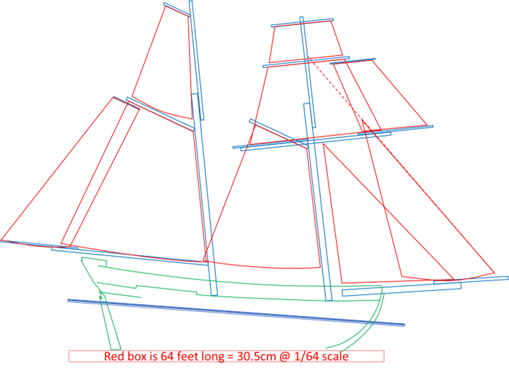
Masts and yards Back to model making again and I have made a start on the masts and yards. Admiralty drawings are the original source of most information about the hulls of Royal Navy vessels but they often tell us little about the masts, yards and sails. Whiting is no exception and all that we can glean from the drawings for Haddock and Cuckoo are the diameters of the two masts and the bowsprit (6mm) and their positions and angles. For ships and brigs there are established rules for proportions with which we calculate the sizes of the spars from, typically, the length and breadth of the hull. The situation for schooners is not so simple and the rules given in different, near-contemporary books are not consistent and give different answers. For example, the length of the main mast from deck to top is given as 208, 194, 230 and 223 (mm at 1/64 scale) by Fincham, Rankine, Cock and Hedderwick in the mid-1800's. Two later books, Lees and Mondfeld, have answers of 152 and 161mm. Phil has done some outstanding work in Excel to combine all these results and I have drawn heavily on his work. Thank you Phil. An alternative approach is possible with the Admiralty drawing of the sail plan for HMS Adonis shown in ZAZ6196. Adonis was a Bermuda built schooner, very similar to the slightly smaller Fish class, built soon after the Fish schooners in 1806. It is very likely that the rules for masting of Adonis were the same as those for the Fish class. I took a pragmatic approach and changed the scale of the Adonis drawing so that the waterline length of the hull was reduced and made the same as Whiting. The lengths of the masts and yards taken from this reduced drawing could now be transferred to the Haddock drawing, making allowances for the different angles of the masts and bowsprit. (The length of the main mast with this method is 196mm and Rankine's formula happens to be closest for this dimension.) Adonis also has a different arrangement of jib sails in comparison to the descriptions written by Sub-Lieutenant John Roach in his log book and a few adjustments are needed to allow for this. The diameters of the spars apart from the two lower masts and the bowsprit are now found by comparing the answers from the various rules and using judgement. As one example, the maximum diameter of the spread yard had a range from 2.8 to 3.1mm and I chose 3.0mm. The diameter of the jib boom could be between 2.0 and 3.0mm and I chose 2.5mm. It might to possible to find a 'true' answer but this method gives parts which look right and the variation is within modelling tolerances. The masts, yards and sails for Whiting are in the drawing below. This is my outline plan. The spars now have their lengths and maximum diameters and can be drawn in detail for model making. Similarly, the basic outlines of the sails need to be refined. I am now working on the bowsprit and jib boom and it is taking a lot longer than I anticipated. The current status of the bowsprit is shown below. The puzzle that I am tackling now is where to put several eyes on on the bowsprit cap to attach eight ropes, as well as mounting a jack staff and a martingale (dolphin striker). The contemporary sources I have are arguing amongst themselves as usual. George
-
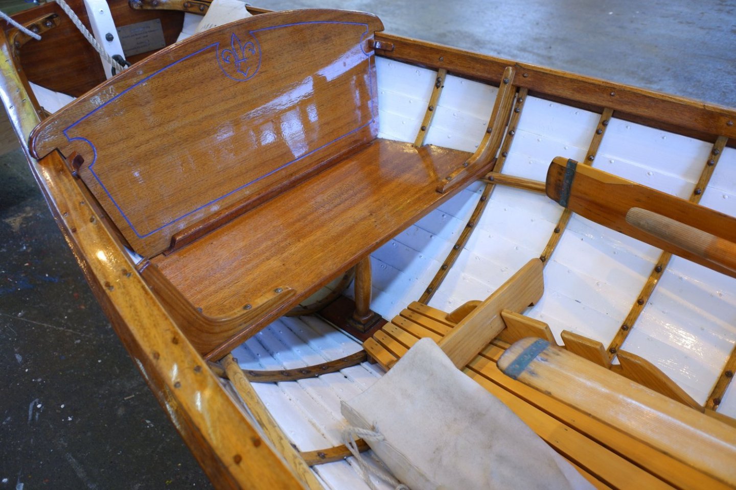
Here's a photo of a restored gig at Portsmouth (UK) which has angled footboards which can also be adjusted for length of leg. This footboard has three slots into which it can fit. George
-
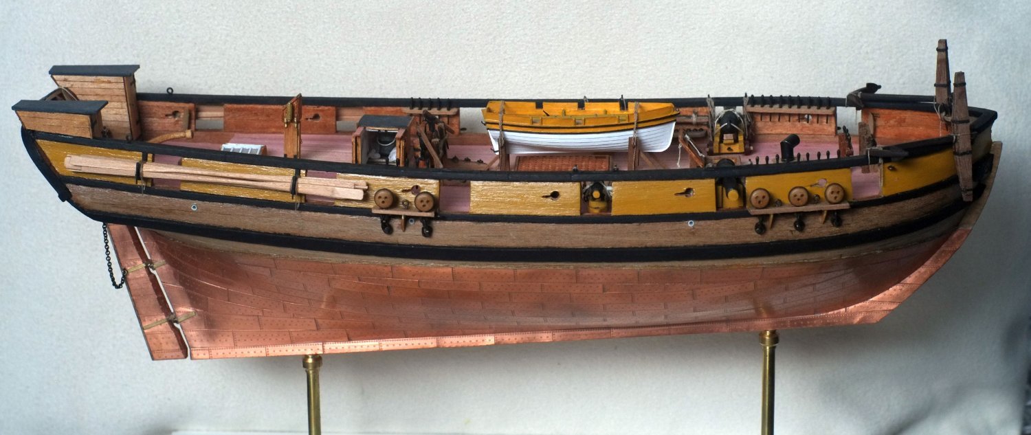
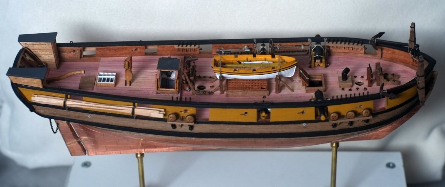
A few photos to show a milestone in the build. (The pumps are standing loose at the moment so I can move them out of the way when rigging.) As I said above, the next big job is the masts and everything that goes on them. George


-
My experience with Caldercraft dowel and plywood has not been very positive. The keel and bulkhead parts were a very loose fit and measurements showed that the ply was 3mm thick and the slots were 3.2mm wide. It suggests that someone thought that 3mm and eighth inch looked the same and could be substituted. Similarly, the dowels were too big to go into the slots in the keel though that problem was easy to solve by sanding a couple of flats on the dowel. I hope that Caldercraft has improved since then. I agree with comments above that the dowels will acquire various tapers (and even octagonal sections) when they become spars and a small difference in the size of the original stock is minor. If you do want to reduce a diameter then grip the dowel with sandpaper and thick gloves and either spin the dowel with an electric drill or rub the sandpaper up and down along the dowel while slowly turning it with your other hand. I don't like the noise of a drill and use the manual method. For tapering I have used a small plane to get the basic shape right. George
-
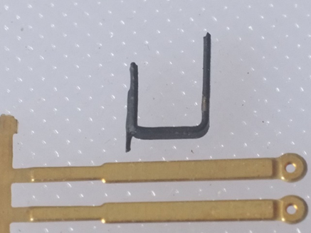
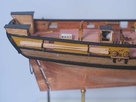
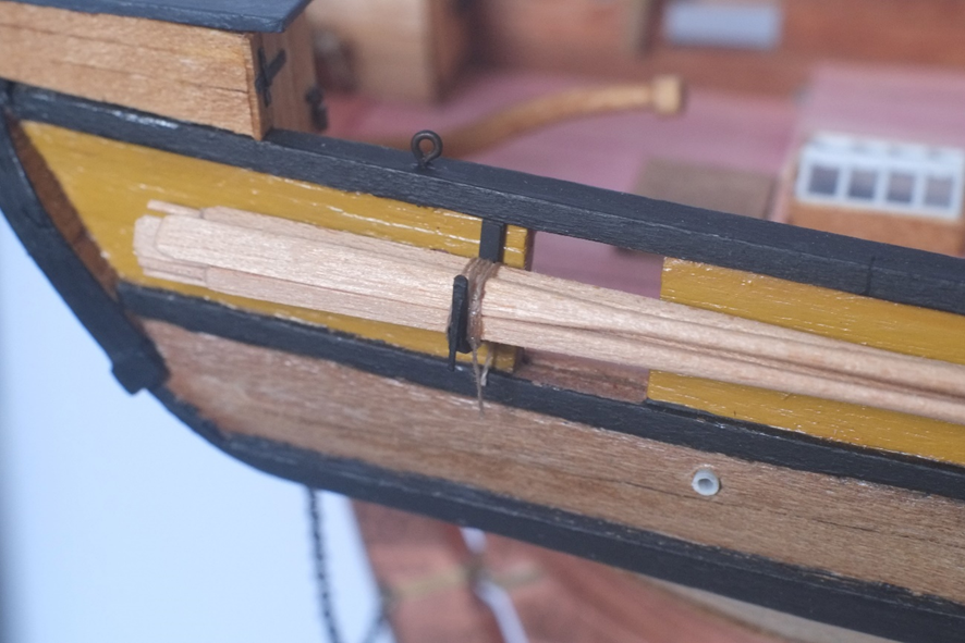
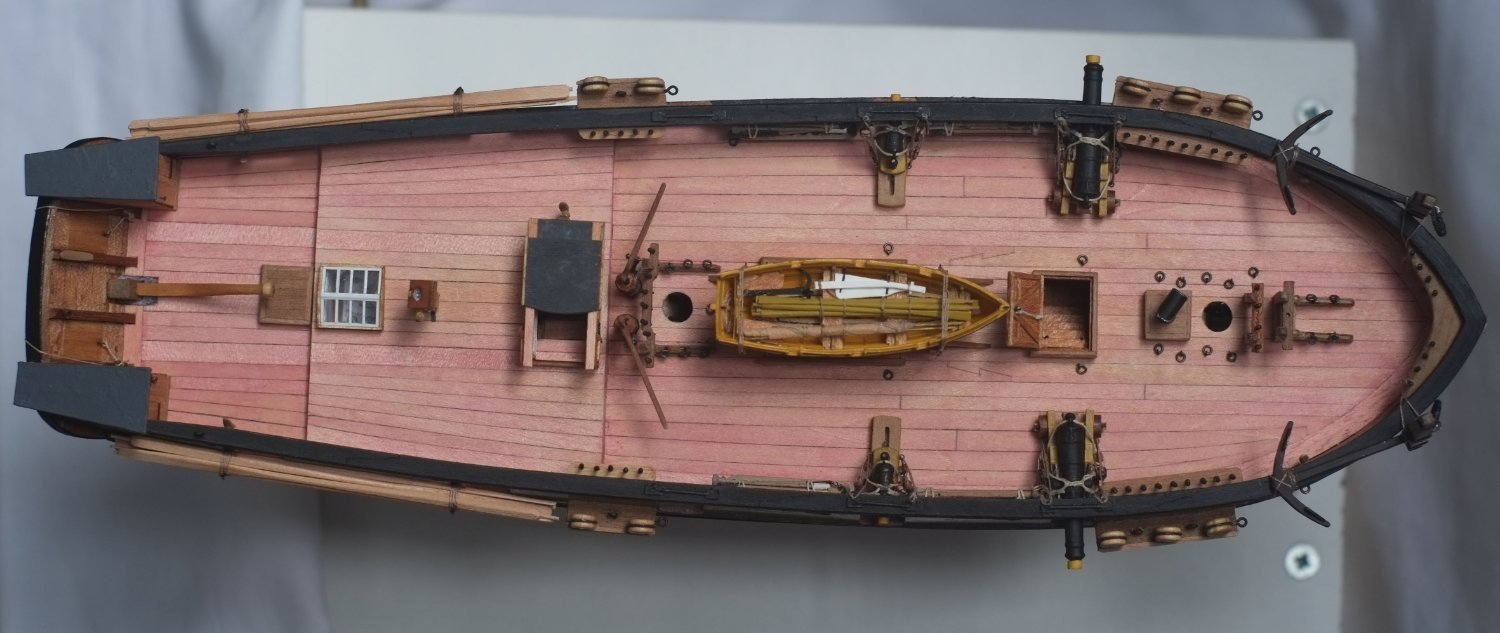
Sweeps continued I made brackets from the etched brass 'chains' that came with the Ballahoo kit. I cut off the eye and filed all the edges smooth. The narrow section is then bent through 90° to form a 4mm long upright. A second right angle bend defines the base which is just over 4mm long internally. The remainder is a longer upright that will be glued to the bulwark. I glued a short length of thin, scrap, etched brass fret to the narrow section so that it projects a little below the base and is there to stop a lashing rope from riding up the side. The brackets are painted black. I glued the brackets between the gunports and their adjacent sweep ports with the top touching the underside of the gunwale. This looks reasonable and supports the oars in a balanced way. There are six sweeps on each side, three with their blades forward and three with the blade aft. I tried to arrange them in a cleverly designed pattern but gave up and let them fall into a natural arrangement when I tightened a thread around them to hold them to the brackets. I tied the ends of the thread with a reef knot and let the ends hang down. The hull is now mostly complete. The remaining additions will be Some figures to give a sense of scale. I have Captain Amati and his crew already. A spare spar or two, probably tied on top of the gunwales at the aft end of Whiting. The anchor rope on one side. Refitting the pumps that I took out while building the housing over the main ladderway. Making drivers for LED lights that connect to the optical fibres I installed to illuminate the interior. The masts and spars and sails and rigging are the big job that will wait until my next modelling season because I will need to change direction and concentrate hard. Lots of judgement calls needed for them. George