

BareHook
-
Posts
430 -
Joined
-
Last visited
Reputation Activity
-
 BareHook reacted to shipmodel in Queen Anne's Revenge 1710 by shipmodel - FINISHED - 1/36 scale
Thanks for all the nice compliments.
Michael - I will trade some of my carving skills for your metalworking expertise. I just finished reading your log of the Bristol cutter and was blown away.
Ken - yes, the jaw is the major problem, but the width of the eye sockets also seemed too broad. Here is the face after narrowing. The lion is coming along nicely, but has a ways to go. If my artistic skills are up to it, I want to get a ferocious expression, but that may be hoping for too much.
After putting the lion to bed for a while, the next independent pieces that I turned to were the mast tops. By 1710 in France they were circular but without the earlier raised rim. They are built with the usual overlapping plank construction, a flat rim and radial cleats. Here are Budriot’s plans, which are almost identical to Lees’ and Marquhardt’s. This is the main top, but the fore is identical, other than being scaled down just a fraction. The mizzen top is smaller, but the construction method for all three is identical.
To build them, the first piece to be made was the square filler piece. It is just a piece of 1/8” thick scrap, sized to the lubber’s hole on the plans. The cryptic symbol on this one is left over from its use as a jig for a previous model. I cut this carefully on the Preac, as it will guide the rest of the construction.
The planks are 1mm thick birch, cut to width and long enough to span the diameter of the top. On the real ship they would have been cut thick then carved down to make the lap joints, leaving a raised portion in the center. Instead, I took a piece of the planking and cut sections the length of one side of the filler guide. These were then glued to the center of the planks with the edges matched up. When the glue was dry one edge was colored with a black marker. A completed one is just above the filler guide piece.
The cleats in the lower left are mass produced since the fore and main tops take 16 each and the mizzen top takes 12. I cut a rectangle of 1mm cherry sheet with the grain going in the short dimension. Then I glued another strip on top of one edge with an overhang equal to the width of the rim with the grain also running in the short direction. Now I could part off 1/16” wide cleats with a narrow blade in the table saw until I ran out of material. The cleats are left raw at this point and will be shaped and tapered later.
To start the platform construction, four of the lap planks are positioned around the filler guide. Two of them (top/bottom) have the thick section turned up and the other two (left/right) have the section facing down. They are glued at their overlaps and clamped tightly around the filler guide.
When they are solid it is easy to lay in the other down facing planks and glue them to the underneath planks and to each other. After the clamps are removed the platform was flipped over and the remaining planks were glued across the first sets of planks.
The center of the filler piece was located and the outer perimeter of the top was drawn with a compass. This was cut close on the band saw and left rough, to be taken down to the line on a disc sander after the rim is installed.
With the compass still set for the perimeter size, an arc was drawn on a rectangle of the cherry sheet, this time with the grain running the long way. The compass was closed the width of the rim and a second curve was drawn inside the first but with the same center. Three more pieces of cherry were stacked under the first and glued together at the upper corners and lower center only, not where the rim pieces will come from.
The inside curve was cut on the band saw then smoothed to the line with a sanding drum in the drill press. The outer curve was cut large, to be sanded down after installation on the platform. After completing the second cut the pieces separated automatically. The rim pieces were cut to one quarter of the circumference of the platform using the plans to make the initial cuts, the fine tuning being done during assembly.
With the platform, rims and cleats made, I assembled them with neutral pH PVA glue. Care has to be taken to see that the cleats are equally spaced and the rim pieces match up to each other, but otherwise construction is pretty straightforward.
The shafts of the cleats were made overlong so their tails extended into the lubber’s hole. These tails were clipped off and the shafts tapered from the rim to the hole with a flap-wheel sander.
All of the corners and edges were cleaned up and rounded with a sanding stick then the top was given its first coat of finish.
Here I used Floquil clear flat, but with a few drops of my stain mixture (50% Natural, 25% Cherry, 25% Early American) added. The finish enhanced the color of the cherry while the light stain brought the tone and hue of the birch into the same color family. It even slightly enhanced the grain of the birch, as if it were older wood. This is exactly the effect that I was looking for. I think that I will be using this color palette a lot as the build continues.
The trestletrees and crosstrees were cut to length from 3mm x 6mm pear. I used the Preac to cut the notches in the trestletrees to accept the crosstrees. Tapers were sanded on all eight arms as shown on the plans, then they were installed on the underside of the platforms.
Holes for the crowsfoot lines were drilled through the forward rim. I spaced them a bit closer together at the center to account for the anticipated narrowing effect as the top curves away from the euphroe. I’ll see how that works out when it is rigged.
The elongated holes for the upper deadeye strops were roughly cut by drilling two holes side by side then using the drill bit to nibble out the wood between them.
Finally, I indicated the nails that hold the two layers of planking together where they overlap. As with the boats, these were indicated by drilling shallow holes with a #80 (0.012”) drill. A wash of stain mix was flooded over the holes and immediately wiped off. It darkened the holes without changing the color of the planks. This is a technique that I will use again as well.
There will be additional holes to mount a number of blocks under the tops, but I have not studied the rigging plan enough yet to locate them. For now, here are the six tops ready for storage till needed.
I'm up in the country this weekend, so hopefully I will soon have some progress to share on the hulls.
Dan
-
BareHook reacted to Chuck in In need of Tips and Techniques for making Eyebolts
Depending on what they need to be used for.....you can take some thin gauge wire and fold it in half around a drill bit the correct diameter. Then twist the two tail ends together many times which will tighten up the eye and make a screw-like pin. Slip it off the bit when you are done. The screw like tail will really hold when glued into a pre-drilled hole. There will not be any chance you could easily remove it. If you use stell wire you can get really thin stuff and make eyebolts with crazy small eyes. No monkeying around with pliers needed.
Chuck
-
BareHook reacted to Jeronimo in LE BONHOMME RICHARD by Jeronimo - FINISHED
Hi friends,
construction and installation of the pumps.
Karl
T e i l 3 8
-
BareHook reacted to rafine in Frigate Essex by Rafine - FINISHED - Model Shipways - Kitbashed
I've now done the starboard wale and also some of the stern planking. I planked the counters and a portion of the transom area, but not around the stern windows. I'm not going to do that portion for a while yet (until I figure out what I'm doing).
I then painted the wales. In order to simplify the masking and painting, I had painted the upper edge of the top strake planks before installing them. I used Pollyscale engine black, which unfortunately is no longer going to be available as the line has been discontinued. I'll miss the paints and need to start thinking about alternatives.
Time now to do the lower hull planking.
Bob
-
 BareHook got a reaction from Kimberley in Need help with the shrouds on Revell - Santa Maria
I found the clove hitch to be pretty easy once I tied a few and got into it.
They were a lot easier for me by clipping one end and tying with the other end using tweezers, they were easy to align and tighten to the needed spacing.
Check out my build log of the AVS, as I just finished doing these.
Ken
-
 BareHook got a reaction from tasmanian in Need help with the shrouds on Revell - Santa Maria
Yes, they are made from rope and part of the "standing rigging" so you will use black colored rope, thye should have some type of sizing guide.
The circles are blown up larger details of the mast connections
Regarding the chainplates and deadeyes, the shroud rope should wrap around the circumference of each deadeye.
You want your shrouds to lie alongside each other without any crossovers, tapering out the the chainplates.
You might consider doing them in pairs rather than all-at-once, to help keep them neat.
Go back n forth, attach 2 portside, then the same 2 on starboard etc...
Also dont trim off the excess until all standing rigging complete, so you can do fine adjustments to the tension and angle of the masts.
Ken
-
BareHook reacted to glbarlow in My Process for Planking
I see there is a pinned posting from David Antscherl at the top of this forum. I'm not him, he's the expert. I have and love his books on building the Swan. Therefore I post this with some trepidation.
My thoughts on 2nd planking: Spiling, or tapering, to fit a flat strip of wood on a surface that curves both front to back and top bottom is no small feat. It defies the grain and natural tendency of the wood and is one of the more fascinating, though perhaps tedious, aspects of shipbuilding. There are whole books written on this topic by modelers far more expert than me using precise methods that are far more exacting than what I do. Nonetheless, I thought I’d share my process. I did this for the lost log of the Pegasus and got some nice responses, so here it is again. It's the result of the practice I've gained from completing 14 hull plankings (ok, 7 models twice planked:-)
First and foremost for the 2nd planking to look work you have to have had a good first planking, more than structure and shape it is the surface for the 2nd planking. If it’s wrong you aren’t going to make up for it with the 2nd planking. The first planking doesn’t need to look pretty, but it has to be shaped and sanded to be the hull you want the 2nd planking to become.
The photo shows my pretty simple set of tools used for planking.
For a strip of planking to reach from the bow to the stern, the bow portion (and in some cases the stern) has to be splined or tapered. In order to have the same number of strips at the wider waist as you have at the narrower bow. The key is how to make the math work and how to achieve the double twist to accommodate both curves, deck to keel, bow to waist to stern. I don’t do scarfing or lay battens, I’m too lazy for the first and don’t find a need for the second.
With most ships as with the Vanguard the planks closest to the deck will fit full width, the key is not to take too much advantage of this, you pay for it later by not being able to get the lower planks to work out right. I first set the planks for the main wale as full width (actually the base, the wale is achieved by doubling up on those planks after sanding the fully planked hull), below that I tapered, above it I went full width. I chose to go up from the wale first and then down, but either way works. I cut and overlap lengths above the wale to show the butt joints similar to the decking, but choose to go the full length of the ship below the wale, just my choice.
The second thing I do is the garboard, a full width plank along the keel. I usually cheat a bit and put a second plank here, tapering the bow side only slightly. The garboard is historically accurate, but in the case of modeling ensures you have a good base and a consistent point to measure from for tapering the planks below the wale
The color differences are due to variation in the planks provided with the kit, since I'm painting the hull it's just the one I picked up next.
Measure what? I use a piece of paper and measure the distance from the bottom of the wale to the top of the garboard at the waist and divide by 5. Since I’m using 5mm wide planks I then know me how many planks I’ll need to cover the ship. So if the measurement is 100mm, then I need twenty 5mm planks to cover the waist.
I do that same measurement at the bow and divide that number by the number of planks above. If the length was 60mm I know the plank width at the bow has to be 3 mm to get those same 20 planks to fit to the stem of the bow.
Pretty simple. All I have to do is use my Exacto knife with a really sharp blade (I change blades a lot) and cut the plank from 5 to 3 mm wide. Here’s the trick though, where to start the cut to begin the taper. I’m sure there are much more methodical and mathematical ways to do this, but I just let the plank tell me. I cut the angle required at stem, bevel it, then matching the end of the plank to the bow, lay the plank along the length of the one above it. It fits snug along the waist and for most of the length of the ship, where it crosses the plank above as it closes in on the bow stem is where I mark with a pencil to start the taper. I mark a 3 mm width at the stem end, lay my heavy steel rule across the two marks I’ve now made, and cut the taper.
If the taper start point is too close to the stem, it will be very hard to get the plank to lay flat, if it is two far from the stem a S-curve will begin to develop with the distance between the last laid plank not being proportionately equal at the waist and bow. If this happens I can adjust by where I cut the next plank or if I see it happening soon enough, toss that plank and cut a new one. As long as I carefully locate my marks it doesn’t happen, its just when I get rushed or bored. I re-take the measurements every 5 planks or so to make sure I’m still on target, it doesn’t vary much but its worth checking to avoid very narrow stem plank widths as you reach the garboard.
Measuring in this way gives me a good looking bow, doesn’t require battens, is simple enough to do, and is made possible by using cyano, not PVA glue. The cyano can be a bit messy, I may be a little over generous with its use, but this comes off easily with sanding and allows the process to move along more quickly. I’d be more careful with the cyano to avoid staining if I was leaving the hull natural (as I did using cherry wood with the Pegasus) but since I’m painting, smooth is all that’s required.
This same process applies to the stern for some but generally not the majority of planks. Here is more important to let the plank follow its natural flow. This will create triangular gaps that are filled with stealers. Simply cut triangles cut to fit the length and width of those gaps unless you want to go all out and scarp them in. Again, I’m painting and scarping the hull, this would be wasted effort for me (unless you enjoy knowing and doing it then by all means).
I do all this knowing that no matter how careful I am, I have always had to fill in some area at the waist with partial and oddly cut planks that don’t reach stem to stern. This fill is on the bottom and won’t be seen once its on the stand so I don’t worry about it, the perfectionist in me adjusts and accepts.
So that’s my two cents. I’m sure as always there are better, more precise, and more expert ways to plank and several of those are included in this forum. But this way works for me and the speed and pace I chose to work. For what its worth I share it with you.
-
BareHook reacted to rafine in Frigate Essex by Rafine - FINISHED - Model Shipways - Kitbashed
I've completed the upper hull planking on the starboard side and done the treenailing on that side, as well. All of the procedures followed the methods used on the port side earlier ( boxwood planking, caulking simulated with pencil, treenails simulated with Elmers walnut filler, coat of Wipe-on Poly as a sealer). Finishing a section of treenailing always feels good,like when you stop banging your head against a wall.
Now it's on to the starboard wale and some stern planking, before tackling the lower planking.
Bob
-
BareHook got a reaction from Kimberley in Need help with the shrouds on Revell - Santa Maria
Yes, they are made from rope and part of the "standing rigging" so you will use black colored rope, thye should have some type of sizing guide.
The circles are blown up larger details of the mast connections
Regarding the chainplates and deadeyes, the shroud rope should wrap around the circumference of each deadeye.
You want your shrouds to lie alongside each other without any crossovers, tapering out the the chainplates.
You might consider doing them in pairs rather than all-at-once, to help keep them neat.
Go back n forth, attach 2 portside, then the same 2 on starboard etc...
Also dont trim off the excess until all standing rigging complete, so you can do fine adjustments to the tension and angle of the masts.
Ken
-
 BareHook got a reaction from avsjerome2003 in Need help with the shrouds on Revell - Santa Maria
Yes, they are made from rope and part of the "standing rigging" so you will use black colored rope, thye should have some type of sizing guide.
The circles are blown up larger details of the mast connections
Regarding the chainplates and deadeyes, the shroud rope should wrap around the circumference of each deadeye.
You want your shrouds to lie alongside each other without any crossovers, tapering out the the chainplates.
You might consider doing them in pairs rather than all-at-once, to help keep them neat.
Go back n forth, attach 2 portside, then the same 2 on starboard etc...
Also dont trim off the excess until all standing rigging complete, so you can do fine adjustments to the tension and angle of the masts.
Ken
-
BareHook reacted to Pete Coleman in HMS Surprise by Pete Coleman - Artesania Latina - 1:48th
Here is a link to my Picasa web album charting my "Super-Detailed" build of HMS Surprise.
I have attempted a compromise between all available sources of information on the subject.
I did have a build log on the original MSW site but alas it's all gone now.
Cheers,
Pete.
The link is no longer valid.
-
BareHook reacted to Pete Coleman in HMS Surprise by Pete Coleman - Artesania Latina - 1:48th
A few more pics.
Cheers,
Pete.
-
BareHook reacted to shipmodel in Queen Anne's Revenge 1710 by shipmodel - FINISHED - 1/36 scale
Hello to all -
Those of you who followed my building of the Swan 42 racing yacht may experience some temporal whiplash as the Wayback Machine moves the shipyard some 300 years into the past. Even though the scale will be about the same, the materials, methods, and style will have little or nothing in common with the last project. We leave the clean lines and millimeter accuracy of a rich man's toy for the rough outlines and incomplete draughts of a pre-Colonial pirate ship.
Queen Anne's Revenge was the flagship of the notorious pirate Edward Thatch (incorrectly called Teach), known as Blackbeard. In barely more than a year and a half, from the summer of 1717 to November 22, 1818, he and two other pirate leaders put together a large fleet that took numerous merchant ships, looting them and holding any worthwhile captives for ransom while taking any willing sailors into his piratical crew. He was hardly the most notorious or bloodthirsty pirate, but he captured the popular imagination with his large fierce black beard and his habit of placing lit rope matches for his weapons into his hair during a battle.
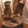
The origins of the ship herself are not definitively known. It is thought that she was built in about 1710 as a small frigate of about 300 tons known as La Concorde, with her first cruise as a French privateer during Queen Anne's War in 1711. When the war ended in 1713 with the Treaty of Utrecht her owners sent her into the slave trade. She made two profitable cruises between 1713 and 1717, taking slaves from West Africa to the French colonies in the Carribean and capturing prizes on the return leg back to France. On November 28, 1717, during her third slaving cruise, she fell afoul of Blackbeard with two armed sloops. Her crew was sick and many of the cannon had been removed to make more room for slaves so she was captured easily. Below is a drawing of a similar light frigate from the early 1700s.
After renaming her Queen Anne's Revenge and adding significantly more cannon, she became Blackbeard's flagship and was used to capture numerous ships and even to blockade the port of Charleston for a week. Turning north from there in company with several smaller pirate ships on June 10, 1718 they tried to enter a shallow anchorage known as Topsail Inlet (or Old Topsail Inlet), now called Beaufort Inlet in North Carolina. Although several other ships entered safely, the larger Queen Anne's Revenge grounded on the sand bar at the entrance, as did another ship that came to her aid. After removing the valuables she was abandoned and left to the cruel mercies of the sea. Blackbeard himself lasted barely another six months until his death in November of 1718 during a battle with the Royal Navy.
The ship was rediscovered in 1996 and is now being excavated underwater in project managed by the North Carolina Department of Cultural Affairs and the North Carolina Maritime Museum, part of East Carolina University. Numerous artifacts, including several cannon, coins, navigational equipment, and hundreds of everyday items have been recovered and are being conserved. You can see photographs of the artifacts, view interactive maps of the ship's history and the wreck site, and read the archaeologists' and researchers' detailed reports if you go to the Queen Anne's Revenge website at http://www.qaronline.org/Home.aspx It is a little gem of a site and well worth looking into.
I have been asked to build two display models of the QAR for the Maritime Museum. They will be at the large scale of 1:36, yielding a model of some 48" LOA from the tip of the jib boom to the ensign staff at the stern. It will rise some 44" from the keel to the main truck with a main yard of some 22" with stunsail booms rigged but not extended. The hull is to be solid below the gun deck but open and fully detailed above. She is to have a full suit of sails with all sail handling lines, although several will be furled so the deck can be more easily viewed.
There are no plans or illustrations of the ship, so her apearance is a bit conjectural. As a basis for the model I have been given two sets of plans. The first is a simple, one-page rendering of the lines and profile of a similar small French frigate which was captured by HMS Advice and which is known therefore as Advice Prize.
I am also working from a set of drawings done by Jean Budriot of yet another light French frigate of the period known as Le Mercure. He has written a monograph that is illustrated with numerous detailed drawings of all of the bits and pieces of the ship including several profiles, cross-sections and longitudinal sections, and sail and rigging plans. However, as is his custom, there is no station lines plan from which to derive the hull shape.
These two sets of plans have to be reconciled, not only with each other, but with the known historic facts. For example, it was reported in contemporary accounts and court-martial testimony that the Queen Anne's Revenge had 20 large cannon on board when she went down. Le Mercure is pierced for 10 guns on each side, but the Advice Prize has only 9. The Mercure drawings have the channels for the fore and main shrouds set below the gunports, while the Advice Prize has them above. Le Mercure is shown with a square, open beakhead bulkhead, while the plans for the Advice Prize shows a closed in forecastle. At the stern Le Mercure has a large quarter gallery, rather than the small quarter badge of the Advice Prize. But that quarter badge is set very high, with an indication that the Advice Prize had a poop deck above the quarterdeck. These and many other details, large and small, will have to be reconciled as construction continues.
To begin with, a tenth gunport was added to the Advice Prize and their spacing was adjusted accordingly. The quarter badge was lowered and it is this resulting profile that will be used to build the models.
On this plan you can see a horizontal red line. This is my line of demarcation between the solid hull below and the open gundeck above. It is set at the level of the gundeck for the forward four ports. A tapered piece will be added at the rear half of the ship to account for the sheer rise of the gundeck towards the stern. But this line is also used as my registration plane for setting up the templates for the hull shape at the various stations shown on the plans.
As I was working out the hull construction the first of what will surely be many problems arose. In the scale that is required, the maximum breadth of the model works out to just over 9 inches and the station lines work out to, mostly, 3 inches separation. To work from the centerline I would need wood of at least 4.5 inches wide and 3 inches thick. However, wood of that size is not easily or inexpensively acquired. Instead, I found basswood planks 4 inches wide and up to 2 inches thick. I decided therefore to piece together the hull.
As you can see in the wood blocking plan below, I started with a vertical central piece 3/8" thick to match the width of the keel. This was sandwiched on each side by a vertical lift 1/2 inch thick, then by the side pieces whch would be cut to the profiles of the appropriate station lines from the plans.
As usual with vertical station line lifts, they were cut to the profile of the appropriate station line. For each three inch station segment a two inch lift and a one inch lift were used. I also decided that the hull should be partially hollow, not only to reduce weight, but to give the stresses somewhere to go other than outward when the wood swelled with changing humidity. My solution was to take each lift and cut out the center, leaving a crescent of wood about 1 inch thick. Construction began with the gunport deck piece cut to shape and the three vertical central pieces glued to it using carpenters' squares for alignment. Then the station line lift crescents were glued in place and secured with dowels. Here you can see the first three segments glued and pinned, with the fourth made ready for installation.
This was continued from the center out to the bow and stern, with the final lifts left solid and clamped to the growing hull block. The completed hull block was left to dry for a week before the bamboo dowels were trimmed off.
Now the carving and shaping had to begin to reduce the stepped shape of the lifts. The model is so large that the usual woodworking tools were inadequate in any reasonable time frame. I therefore purchased an angle grinder and set it up with coarse 50 grit sanding discs. This was followed by a random orbit sander, also with coarse grit paper.
As you can imagine, this makes a hellish racket and leaves a hellish mess, Eye, ear and respiration protection are a must, and if you are not going to do all of it outside, you need three other things - an empty room in the basement; a big shop vacuum; and most importantly, an understanding wife. I am glad to say that I have the first two and am blessed with the third.
In this photo you can see how far the shaping has progressed. From here there still has to be a lot of hand work that is checked and rechecked as usual with station line templates. The next segment will take us through that process.
Be well
Dan
-
BareHook reacted to Desert_Sailor in Looking for suggestions on Coils,
Try this,
Use about a 25% solution of water and Elmers. Soak the line in the solution so its very limp..
Using a forcep ( tweezer) start coiling the line to the size you want.. The stickiness of the solution will hold it together.
If it starts to fall away, just dip the coil in the solution again..
Keep coiling until you're about 1.5 -2 coil diameters from the pin rail.
Using a different forcep, reach through the coil and grab the remaining line, pull it through and then loop it over the coil.
Now, loop the "pull over" line over the pin rail and the coil should hang nicely.. Before it dries, GENTLY pull on the bottom of the coil so as to give the coil an oval shape. This give the appearance of the weight of the line hanging normally,
When the water evaporates, the Elmers that
remains will dry clear and the coil will be rigid enough without looking too stiff..
See Image below..
-
BareHook reacted to rafine in Frigate Essex by Rafine - FINISHED - Model Shipways - Kitbashed
Thanks for the interest, Ben and Kurt. But that's enough of Flying Fish for some months.
Back to business on Essex. A small update. I've installed the wale on the port side ( the stern still needs to trimmed). The wale is made of three strakes of boxwood. Later, it will be painted black. Now it's back to the starboard side and maybe some stern planking.
Bob
-
 BareHook got a reaction from Ryland Craze in Armed Virginia Sloop by BareHook - FINISHED - Model Shipways - 1:48 - First Wood Ship Build
The ratlines are complete and I'm very happy with the results
I also added one additional row on each side below the cleats per Alistair's suggestion.
I found the clove hitches worked very well and retained their tightness until locked with dilluted white glue, and I was able to trim the tag ends very close.
I also used .012 black line instead of the .021 per the instructions for better size contrast and more accurate sizing.
Confession: I decided not to serve the standing rigging on this build, but will try it in future builds I plan to invest in the serving machine in the near future.
I'll install the Topmast fore and aft stays and then I need to set up and install the main sail.
I'll probably have her rigged on (at my best laymans guess) a port tack? Where the main and fore sails are rigged to the port side and the top sail angled with the starboard side forward.
I'm probably going to stiffen/shape the sails a bit with hairspray while a fan is blowing on them.
Please provide info if my terminology is wrong, thanks!
Ken
-
BareHook reacted to dcicero in Mystery Gun: Anyone know what this is?
All:
A friend's son is working on his Eagle Scout project. He contacted a local VFW hall and asked if he could clean up the gun outside the post. Here's a picture.
There's a nameplate on the gun which identifies the carriage as a 4" carriage, Mark XII, Mod 1. It was built by the Goss Printing Press Company of Chicago, IL in 1918.
The gun was moved to the VFW hall a long time ago from a park in Aurora, IL. No one has any information about it. The project is finished now. The base was cleaned and painted. The old paint was scraped off and the gun repainted. All the brass has been shined. All the weeds have been removed, new flower beds cut in and mulch laid down. The gun looks much better than it did.
To finish the project off, the new Eagle Scout is going to make a presentation to the VFW Post. I'd like to help him put in some information about the gun itself.
Anyone got any ideas what this gun is? Where might it have been used? (I'm thinking it might have been a coast defense gun.)
Dan
-
 BareHook got a reaction from riverboat in How to do deck edging?
On my AVS kit, I did the planking first, then added the Nibbing Strakes after. I traced the shape with tracing paper and transferred it to wood plank.
I cut it out slightly oversize so it could be fine tuned by sanding for an accurate fit.
Ken
-
 BareHook got a reaction from Brian the extraordinaire in How to do deck edging?
On my AVS kit, I did the planking first, then added the Nibbing Strakes after. I traced the shape with tracing paper and transferred it to wood plank.
I cut it out slightly oversize so it could be fine tuned by sanding for an accurate fit.
Ken
-
 BareHook got a reaction from Ponto in How to do deck edging?
On my AVS kit, I did the planking first, then added the Nibbing Strakes after. I traced the shape with tracing paper and transferred it to wood plank.
I cut it out slightly oversize so it could be fine tuned by sanding for an accurate fit.
Ken
-
BareHook reacted to tarbrush in Why not paint your ship?
BassicBill, sorry about the slow response, my internet has been out since yesterday. I just went and snapped a couple of pictures of the old girl, she got knocked around pretty good on my cross country move and I have repaired her yet. shame on me. but here a couple of pics.
-
BareHook reacted to johnegert in Why not paint your ship?
Tomas----
I owned one once, but had to close. The wretched customers spilled glue on everything, often attaching themselves to the glassware permanently. They never had any money, always yammering about "saving for the Agamemnon", whatever THAT meant. Then,one night, I hired the Rolling Stones to play, and the customers walked out because the band refused to play "chanteys and hornpipes". They also had an unnerving tendency for self-mutilation, with one bizzare woman taking an xacto to her own hand....horrible. The last straw: Every time I served a nice tall mug of hot Irish coffee, the bastards would stick planking in it.
I don't need that kind of grief....
john
-
BareHook got a reaction from Kimberley in Start up or down on the sails?
With plastic sails, maybe pierce the corners with a hot needle or use a small drill in a rotary tool?
Not sure about rigging order, but I've found they generally follow how you would do it on an actual ship which would be from the bottom up.
I haven't built a plastic model in about 35 years though and am just on my first wood model so...
Ken
-
BareHook reacted to rafine in Frigate Essex by Rafine - FINISHED - Model Shipways - Kitbashed
I added the remaining planking down to the wales on the port side and was about to do the wales when Sam informed me that he would have previously omitted material on the wales ready soon, so I decided to wait. That brought about the end of my procrastination on the treenails. Probably to the surprise of no one, I decided to go ahead and do them.
After marking and drilling what seemed like an endless number of holes, I filled them with Elmers walnut filler.This is probably a little dark, but I liked the look better than using golden oak, which I have used in the past. Considerations of the small scale, and aging eyes and hands, led me to use an arrangement of the treenails which is more stylized than accurate, but which I think (hope?) gives the right impression overall. After filling and sanding, I applied a coat of Wipe On Poly for protection. Now, I can do it all over again on the other side.
Bob
-
 BareHook got a reaction from GuntherMT in Armed Virginia Sloop by BareHook - FINISHED - Model Shipways - 1:48 - First Wood Ship Build
The port ratlines are now completed. I'm happy with how they turned out. I used the clove hitch at all 4 points and just trimmed the ends off close.
Once I got the method down, I found it pretty easy. I started with every 5th to hold the spacing and then filled in from the bottom up. The template clipped in place behind really helps as well for keeping your spacing, and providing a contrasting background for grabbing and knotting the ratlines.
Following this method, I found it easier to tie by clipping one end of the string and working with the other end for the first knot:
Clip one end to the edge of the template card, near the height of the ratline, remove after first knot. Tie the center two knots, adjust height with small tweezers. Tie the outer two knots, adjust height with small tweezers. Repeat until the section filled between every fifth that were first installed. Double check alignment and tightness of all ratlines tied in group. Lock all knots with dilluted white glue. After glue has dried, trim off ends and start next group. I was able to complete a set of 4 ratlines in 10-15 minutes.
Ken