


Beef Wellington
-
Posts
2,249 -
Joined
-
Last visited
Reputation Activity
-

 Beef Wellington reacted to BenD in HMS Snake by BenD - Caldercraft - 1:64
I upgraded my workstation once again. This time I got a new desk and some cheap Ikea lamps that can use 800 lumens bulbs. I now have more desk space than I know what to do with.
So many hours have gone into prepping parts and painting for the Carronades. I can't even begin to imagine doing all the guns for a frigate or a ship of the line. Anyway I tried using a black deckblock to see If I liked the contrast or not, backed out of that pretty fast.
-
 Beef Wellington got a reaction from drtrap in HMS Snake by Beef Wellington - FINISHED - Caldercraft - Scale 1: 64 - First wooden ship build
Hi Folks, have been away from the shipyard and this site for quite some time, and I've missed the friendly interaction. Looking forward to catching up with everyone's builds soon!
@Martin - welcome to the neighborhood! We got lucky and didn't lose power in the storms, hope you stayed safe. We definitely need to connect at some point so I can pick your brains 🙂
@ Sjors - Good to hear from you old friend, its been a while! Will check out your new model soon.
@ Stergios - the yards were rigged from bottom to top. Not sure if that is the recommended way, but it made sense to me to do that way because the lower masts require quite a few items of rigging to be in place near the mast and it seemed that this would be harder if the lines from the top masts were getting in the way. Maybe personal preference?
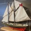
The cutter has finally been finished and the details of the final stages of construction are posted in my 'Jason' build log. Figuring out where to place the cutter onboard Snake was a little bit of a challenge. It seems inconceivable that a ship (sloop) like Snake would not have at least one boat, but there is simply no space to place one. I could find no examples of solutions to this in practice (recognizing that other ships may well have had raised davits), and it seems somewhat logical to mount the supports on the coamings which would also be supported by the deck beams underneath. Finally in position, its clear that even a modest 24' cutter has little room to spare.
With that done, now rigging can continue, hopefully some progress possible soon...
-
 Beef Wellington got a reaction from PaddyO in HMS Jason by Beef Wellington - Caldercraft - 1:64 - Artois-class frigate modified from HMS Diana 1794
Many thanks all for the comments and likes, definitely good to have people along for the journey..
Feels like a chapter is coming to a close, finally seem to be closing in on completing the upper deck. Definitely a multitude of time consuming small tasks. First off I needed to address the fixed part of the gangway. This is shown quite clearly in plan view on page 46 of AOTS Diana, however it is not shown in profile. Given that it appears to contain its own lodging knee, I decided to extend the profile of the deck beam. This seems to make sense when recognizing that a ladder will eventually be located here. This highlights one of the inconsistencies in the AOTS book, many diagrams show the non-flush gangboards which I understand were going out of fashion at this point to be replaced by flush gangboards. Hoping I'm not too far off the mark here. A strip with a slight profile was added also to the deck beam to sit flush with the false quarterdeck.
The base plate to the stove was ripped off and replaced despite my intentions to leave as, hopefully this sits a little more harmoniously.
Cables have been added and "secured" to the various ring bolts beside the midship gratings. AOTS describes these as being used for stoppers, but decided to secure with simpler ring ropes as described in Lever. Stoppers have been modelled as per Lever on the 2 foremost ring bolts, but not yet tied on or attached permanently to allow me to finally decide (or others to refute) the approach taken.
Even though this area will only ever be glimpsed, time was spent fully building out the area around the foremast with the For jeer and for topsail sheet bitts as they would appear. The actual bitts on the fo'c'sl will be mounted to the deck, seemed unnecessarily complicated to build these fully. Couldn't quite figure out what was represented on diagrams for the fore jeer bitts until I saw interior photos of contemporary models in the Roger's Dockyard Model collection - but still no clue what the "swan neck" arrangement is called. What is very interesting is how crowded this forward area really is, fighting these guns must have been a real challenge.
Warning: Here follows some highly indulgent closeups taken on Captain's rounds! This is the closest I guess I'll get to seeing what this looked like in practice
And finally...some overall shots with where things stand..
-
 Beef Wellington got a reaction from Sjors in HMS Jason by Beef Wellington - Caldercraft - 1:64 - Artois-class frigate modified from HMS Diana 1794
Quick update. Increasingly realizing I'm reaching a point that I need to attach the upper false foc's'l and quarter deck template before more progress can be made, but a couple of items I need to finalize and figure out first.
Main and mizzen backstay stools:
Unfortunately when I made the channels I neglected to make the stools at the same time, In a moment of focus decided to just get these done. These smaller items were definitely trickier than the channels when scraping the edge profile, other than that, these can be put aside for when I'm ready to install the quarterdeck drift rail.
Upper deck coamings:
As mentioned previously, I'd like to keep the option to have a few of the gratings be removeable. First off, appropriately sized gratings were made up, and the coamings then sized accordingly. I cheated here and used a simple butt joint as I didn't think the more authentic lap joint would really be visible. These were made of 3x3mm strip and 2x3mm strip with the inside ledge added after with some slightly thinned 1mm strip. The grating thickness had to be thinned quite a bit to make it them sit flush. These will also be simulating actual practice and so the edges were rounded off to 1mm above the bottom to butt up against planking. TFFM was used as a guide here.
Once the coamings were finished, the fake beams and cross pieces could be made up to the appropriate size. The ends were sloped to ensure that the end of the face beam would not be visible for viewing angles.
Adjustments were made to the false deck to accommodate the larger openings and positions tweaked a little. For the foc's'l, the coaming size does not match the deck cut-out or AOTS exactly due to the limited incremental options for the grating size. The stove flue needs to sit equidistant between the steam grate and the forward grating which moved forward slightly. The steam grating needs to be positioned appropriately to allow the belfy to sit on the aft end of the steam grate coaming.
The top tackle scuttles have been filled in to ease future planking - the instructions indicate that there should be coamings and gratings here, however, these will be modeled as flush scuppers without a coaming as described in AOTS and shown on contemporary models. Although the surface of the center deck is very slightly curved, it is a close enough approximation to a flat surface that the flat top of the fake frame seem to sit without issue. Lighting is clearly an issue here, and the interior is a little more visible than the photo's suggest, and probably more so in a well lit room.
Of note is the fact that the stove, and especially the condenser, sits a little higher than ideally would be the case, although looking at the AOTS diagrams its still a tight fit there as well. In retrospect, I would probably not have put wooden battens underneath the bottom plate to lower this by 1mm or so, but not going to risk damage at this point to redo.
Putting some scrap planking in place give a better sense for the final proportion and the above deck rounded edge. Think these will be a nice contrast to the much higher coamings of the exposed upper deck below needed to withstand water ingress.
-
Beef Wellington got a reaction from Sjors in HMS Jason by Beef Wellington - Caldercraft - 1:64 - Artois-class frigate modified from HMS Diana 1794
Thanks everyone, need to record a few things before moving on too much further:
Tackles:
Boy, these blighters take time. I will definitely not be fully rigging each gun, but will look to rig those fall into possibly the 'noticeable in the background' category. Here's the method I found works best for me. Apologies for the photos, an iPhone is really not the best at trying to photograph tiny objects suspended in the air.
A hook was threaded with 0.3mm Syren line and some overhand knots tied to seize this securely. Drop of GS Hypo cement to keep secure before trimming excess. The long ends are then placed around the block and loose overhand knot tied.
A length of line for the tackle fall is then inserted into the loop and then threaded back through itself as for a false splice.
Pulling the overhand know tight around the block, and simultaneously tightening the false splice secures the knot around the block. Another small drop of GS Hypo cement on the false splice helps keep this secure, and placing the end of the stropping line into 'helping hands' helps keep the knot tight while the cement dries.
Slightly weighting the tackle fall line (in this case with tweezers) allows the alignment if the block to be tweaked before the cement sets fully. Thin thread can then be seized around the splice to secure it, I find alternating overhand knots gives a pretty secure and easy result. Once more, another drop of GS Hypo on the seizing helps ensure this doesn't unravel once trimmed.
Once completed, I use some dilute PVA glue on the stropping prior to trimming off any excess as some additional insurance as it is a frustrating experience for these to break when frapping. The tackle falls were then fed through the previously stropped double blocks, and then frapped on the service machine as per a previous post. The last turn was secured simply by feeding back through the prior turn and pulling taught. The completed tackle can then be placed where needed and some dilute PVA applied again to the whole tackle - special attention was paid to ensuring the tackle fed through the frapping was secured with glue. The entire tackle can then be removed once dry and the excess line trimmed. Its a simple matter to hook these back into position. Et voila!
Stove:
The stove has also been given a little more TLC and is now glued into position. Handles for the boilers were added, as well as rails which were made from brass rod. The rails were the treated with some JAX 'Brown' to darken it a little a keep it in keeping with the colour of the copper still. As described in a previous post, I've followed TFFM simulating wooden battens under the custom base plate rather than simulating tiles, they would not been seen in any event once the main riding bitts are in place. Temporarily putting the fo'c'sl deck in place shows that much of this will be obscured even if the various gratings are made removeable which I plan to do.
In closing, a quick summary of the 3D printed stove. With a little work I'm happy with the way this turned out. Comparison to the kit supplied version shows the dimensions to be a little more authentic, and the detailing is much more pleasing than the approximations on the supplied white metal parts. To be fair, no work was done to pretty this up, but I'd certainly recommend this as a simple 'upgrade'.
-
Beef Wellington got a reaction from Sjors in HMS Jason by Beef Wellington - Caldercraft - 1:64 - Artois-class frigate modified from HMS Diana 1794
Hi all,
Well finally been able to get some things done that tangibly move things forward. The area around the mainmast is one of the more interesting and complex areas to get situated. All of these items were scratchbuilt, which of course resulted in the usual re-does as the geometry is critical to get right as the pump axel and cranks need to align with minimal tolerances.
Capstan and aft coamings now glued into position, the deck beam needs to be modified to allow the capstan to be positioned appropriately.
Little bit of rework on the pumps, the simulated leather washer I had previously painted kept jumping out at me and was a little too 'in your face'. Stripped this off and went with what seems to be a more traditional modeling approach to use layer of wood to simulate the gasket and plug. Here they are in final position.
The main jeer bitts were then positioned first once the pumps were in place to finalise the dimensions of the middle pump brakes. The kit supplies some PE for these, but knew that these would never be satisfactory and have been planning to make my own. The supplied wire is around 0.8mm, so 1mm square styrene sections were drilled and cut to give a little more of an authentic look to the winches. To say this process is delicate and frustrating is an understatement - once drilled, the there is barely any structural strength to the styrene around the hole. The aft winches were made in one piece which allowed them to be aligned relatively easily and secured using thin CA which worked quite well. Once glued, the styrene was then gently filed to give a hint of the actual shape.
Rhodings were made out of boxwood and painted, to my eye this gave a little better scale look. The stanchions had been made previously, and notches cut into the deck beam to allow these to be secured.
The stanchions were finalized and installed...making the second curved bracing element to be the same as the first took a lot longer than expected.
The layout of the main topsail sheet bitts dictates that the winches need to made separately reflecting actual practice. These longer winches proved much more challenging than the shorter ones, and many were attempted before 2 acceptable ones were completed.
Elm tree pumps were shaped from boxwood stock, and the PE fittings came from an extra set I found left over from my Snake build. These were fun items to make up, but will not be finally fixed just yet as they are very delicate.
Overall shots with everything in place shows just how crowed this area really is. Overall, very happy with how this ultimately turned out. The main topsheet bitts align underneath the deck beam at the forward end of the quarterdeck.
Overlaying scaled copy from AOTS, one can get a good sense for the reason for the scuttles in the quarterdeck which would have been necessary to be able to remove the various pump shafts. I'm considering modding the quarterdeck to allow these scuttles to be left open to allow the pump mechanisms to be better seen.
-
 Beef Wellington got a reaction from Jorge Diaz O in HMS Jason by Beef Wellington - Caldercraft - 1:64 - Artois-class frigate modified from HMS Diana 1794
Hi Folks,
Sadly been rather absent from both the shipyard and this site for some time. I very much hope to catch up soon on everyone else's fine builds here soon. Time to get a little more up to date, the cutter is pretty close to completion aside from a little fettling.
Frames were added to the interior using strips cut from some scrap 0.5mm pear wood. These were soaked and pre-bent in situ prior to gluing with PVA:
The frames were further reduced down to the keel former to try and get a bit more depth the boat. To my eye, applying planking to the false deck puts the board too high, especially as there is very little room to play with considering the various structural elements still to go on. A template for the footwaling was then made up to determine the shape. Once the placement was determined, the rising plank was added (again cut from some 0.5mm pear sheet)
I wanted to try and allow the footwalling to have an element of curvature which would be natural on the real boat. A relatively straightforward way to achieve this was to apply wood strip to thin card to match the template which maintains a lot of flexibility (Straight strip was used rather than the more complicated curved planking on the plan). Once dry, the assembly was easily glued on top of the keel former, the footwaling then follows the interior curve naturally.
With those element in place, it was possible to add the platform under the sternsheets. The Diana plans show these as a grating, but to my eye again the kit supplied grating is too large, so plain boards were installed instead which also appear to be used. After the main and fore mast steps, thwarts and ringbolts I assume would be used for hoisting the boat had been added, the bow was closed in using a cover as suggested on the plan - this also helped disguise the rudimentary construction at the bow. The rowlocks were cut, interestingly these are not symetrical between port and starboard, and one seems to sit rather awkwardly in the sternsheets.
The sternsheets were made up and installed, again having used a template to finalise shape, together with all the other details including mast thwarts, gunwale and knees.
The colour scheme follows a slightly simplified version of that shown below which seems suitably utilitarian. Looking at this, and comparing once the black was applied, suggests to me that I made a mistake in the tapering of the clinker planking. The black area covers both the wash strake and upper strake, and judging from these pictures it appears that these are of somewhat consistent in width, especially toward the stem. I had tapered these proportionally as well, hoping nobody else notices...
-
.thumb.jpg.62d1d69fed1f32364417cb1f9cdeb009.jpg) Beef Wellington got a reaction from WalrusGuy in HMS Snake by Beef Wellington - FINISHED - Caldercraft - Scale 1: 64 - First wooden ship build
Beef Wellington got a reaction from WalrusGuy in HMS Snake by Beef Wellington - FINISHED - Caldercraft - Scale 1: 64 - First wooden ship build
Hi Folks, have been away from the shipyard and this site for quite some time, and I've missed the friendly interaction. Looking forward to catching up with everyone's builds soon!
@Martin - welcome to the neighborhood! We got lucky and didn't lose power in the storms, hope you stayed safe. We definitely need to connect at some point so I can pick your brains 🙂
@ Sjors - Good to hear from you old friend, its been a while! Will check out your new model soon.
@ Stergios - the yards were rigged from bottom to top. Not sure if that is the recommended way, but it made sense to me to do that way because the lower masts require quite a few items of rigging to be in place near the mast and it seemed that this would be harder if the lines from the top masts were getting in the way. Maybe personal preference?
The cutter has finally been finished and the details of the final stages of construction are posted in my 'Jason' build log. Figuring out where to place the cutter onboard Snake was a little bit of a challenge. It seems inconceivable that a ship (sloop) like Snake would not have at least one boat, but there is simply no space to place one. I could find no examples of solutions to this in practice (recognizing that other ships may well have had raised davits), and it seems somewhat logical to mount the supports on the coamings which would also be supported by the deck beams underneath. Finally in position, its clear that even a modest 24' cutter has little room to spare.
With that done, now rigging can continue, hopefully some progress possible soon...
-
 Beef Wellington got a reaction from Timmo in HMS Jason by Beef Wellington - Caldercraft - 1:64 - Artois-class frigate modified from HMS Diana 1794
Hi Folks,
Sadly been rather absent from both the shipyard and this site for some time. I very much hope to catch up soon on everyone else's fine builds here soon. Time to get a little more up to date, the cutter is pretty close to completion aside from a little fettling.
Frames were added to the interior using strips cut from some scrap 0.5mm pear wood. These were soaked and pre-bent in situ prior to gluing with PVA:
The frames were further reduced down to the keel former to try and get a bit more depth the boat. To my eye, applying planking to the false deck puts the board too high, especially as there is very little room to play with considering the various structural elements still to go on. A template for the footwaling was then made up to determine the shape. Once the placement was determined, the rising plank was added (again cut from some 0.5mm pear sheet)
I wanted to try and allow the footwalling to have an element of curvature which would be natural on the real boat. A relatively straightforward way to achieve this was to apply wood strip to thin card to match the template which maintains a lot of flexibility (Straight strip was used rather than the more complicated curved planking on the plan). Once dry, the assembly was easily glued on top of the keel former, the footwaling then follows the interior curve naturally.
With those element in place, it was possible to add the platform under the sternsheets. The Diana plans show these as a grating, but to my eye again the kit supplied grating is too large, so plain boards were installed instead which also appear to be used. After the main and fore mast steps, thwarts and ringbolts I assume would be used for hoisting the boat had been added, the bow was closed in using a cover as suggested on the plan - this also helped disguise the rudimentary construction at the bow. The rowlocks were cut, interestingly these are not symetrical between port and starboard, and one seems to sit rather awkwardly in the sternsheets.
The sternsheets were made up and installed, again having used a template to finalise shape, together with all the other details including mast thwarts, gunwale and knees.
The colour scheme follows a slightly simplified version of that shown below which seems suitably utilitarian. Looking at this, and comparing once the black was applied, suggests to me that I made a mistake in the tapering of the clinker planking. The black area covers both the wash strake and upper strake, and judging from these pictures it appears that these are of somewhat consistent in width, especially toward the stem. I had tapered these proportionally as well, hoping nobody else notices...
-
Beef Wellington got a reaction from WalrusGuy in HMS Jason by Beef Wellington - Caldercraft - 1:64 - Artois-class frigate modified from HMS Diana 1794
Hi Folks,
Sadly been rather absent from both the shipyard and this site for some time. I very much hope to catch up soon on everyone else's fine builds here soon. Time to get a little more up to date, the cutter is pretty close to completion aside from a little fettling.
Frames were added to the interior using strips cut from some scrap 0.5mm pear wood. These were soaked and pre-bent in situ prior to gluing with PVA:
The frames were further reduced down to the keel former to try and get a bit more depth the boat. To my eye, applying planking to the false deck puts the board too high, especially as there is very little room to play with considering the various structural elements still to go on. A template for the footwaling was then made up to determine the shape. Once the placement was determined, the rising plank was added (again cut from some 0.5mm pear sheet)
I wanted to try and allow the footwalling to have an element of curvature which would be natural on the real boat. A relatively straightforward way to achieve this was to apply wood strip to thin card to match the template which maintains a lot of flexibility (Straight strip was used rather than the more complicated curved planking on the plan). Once dry, the assembly was easily glued on top of the keel former, the footwaling then follows the interior curve naturally.
With those element in place, it was possible to add the platform under the sternsheets. The Diana plans show these as a grating, but to my eye again the kit supplied grating is too large, so plain boards were installed instead which also appear to be used. After the main and fore mast steps, thwarts and ringbolts I assume would be used for hoisting the boat had been added, the bow was closed in using a cover as suggested on the plan - this also helped disguise the rudimentary construction at the bow. The rowlocks were cut, interestingly these are not symetrical between port and starboard, and one seems to sit rather awkwardly in the sternsheets.
The sternsheets were made up and installed, again having used a template to finalise shape, together with all the other details including mast thwarts, gunwale and knees.
The colour scheme follows a slightly simplified version of that shown below which seems suitably utilitarian. Looking at this, and comparing once the black was applied, suggests to me that I made a mistake in the tapering of the clinker planking. The black area covers both the wash strake and upper strake, and judging from these pictures it appears that these are of somewhat consistent in width, especially toward the stem. I had tapered these proportionally as well, hoping nobody else notices...
-
Beef Wellington reacted to fake johnbull in HMS Bellerophon 1786 by fake johnbull - Amati/Victory Models - 1/72
Chains
Next step is installation of chains to channel. But I want to tell about some modification to channel firstly.
Correct reasons I don’t know, but some deadeyes and chains are omitted in kit design when comparing actual plan of Slade designed 74 and kit design.
Perhaps kit designer Chris Watton want to escape that channel edge are occupied by deadeyes of slightly larger size from manufactures' stock and deadeyes being crowded each other.
OTOH, AOTS Bellona and NMM Hercules/Thunderer model (contemporary Georgian style hull model with modern rigging) show some of deadeyes are unused.
https://collections.rmg.co.uk/collections/objects/66271.html
If they are correct, numbers of shrouds of kit design isn’t wrong. But I decided to add missing deadeyes to channel.
Surely added deadeyes give crowded impression, but I myself am satisfied with result.
Main mast channels are given another modification. Some of chains for backstays are positioned immediately above gunport, these resulted in their chains are lead horizontally, not diagonally as normal chains.
To resolve them, I shortened their deadeye strops, but chains seem to be still horizontal and not strong. Finally I removed aftend of main channels and altered them to stool channels at upper position. This arrangement is also can be seen on HMS Victory today.
Many contemporary models are showing aftend of fore and main channels reducing their width inward and chains of backstays immediately above gunports are still keeping diagonal angle. But I think my modification gave practical solution.
Now it’s time to tell about chains themselves. PE chain parts are also one of few disappointments of the kit. While each chain assembling should have different length according to its position, kit PE parts are same size. Also preventer plate should have groove alongside their length, but kit PE is merely flash surfaced.
Finally, I decided to make preventer plates and intermediate links by myself. Difference of length of each chain assembling will be controlled by length of intermediate links. I think deadeye strops and toelink in kit PE need no modification.
Preventer plates were made from copper wire with soft-soldering. Maybe I should use brass rod and silver-soldering, but preventer plates don’t directly receive upward forth of shroud. So I use easier material to bend.
Photos themselves tell how I made them than word, so no detailed depiction will be required.
I soft-soldered rearward side of plates, but it is unavoidable solder is flooded into outer surface. So I grooved by file.
BTW, NMM Elephant plan shows two sizes of preventer plates. Fore channels ones and foremost three ones are short and rest are long.
https://collections.rmg.co.uk/collections/objects/81038.html
OTOH, Edgar and other Elephant plan show longer preventer plates are used on foremost two chains of fore channels and they seem to be even longer than main channels ones.
https://collections.rmg.co.uk/collections/objects/80682.html
https://collections.rmg.co.uk/collections/objects/80855.html
I decided to make two sizes of preventer plates for easier work. Also if I add billboard at later stage, plates of different size will be hidden.
After their completion, preventer plates are fitted to hull but only pinned at lower hole. Upper hole will be pinned with toelinks later.
Some building guide books tell that assembled deadeye and chains can be chemically blackened as whole assembling. But I’m afraid that this method ruins surface of deadeyes. I blackened chain parts with Asahipen Metal Primer and AZ Blackening Spray before assembling them. They work well and blackened layer of strop is tough enough to endure against bending force when fitting deadeyes. BTW I add some modification to deadeyes. Top edge of each holes are recessed with electric tool.
Making of intermediate links are also told by photos themselves. Before I started them, I expected depressing work requiring long time, but it finished within much shorter time than I expected. intermediate links require strongness than preventer plates, so I used 0.5mm brass rods.
If test fitting is OK, then soft-solder it. Soft-soldering gives enough strongness unless changing shape of link with strong teightning. Butt end of each link is positioned at rearward for beautiful result.
Intermediate links are blackened on-site. I use toothpick and apply AZ Blackening Spray once prepared on another tray.
Capping pieces are moulded and fitted to channel edges. I used walnut strips included in kit. Boxwood would be better choice for moulding, but I used easily available material.
Bellows are latest status of my building.
Next, I want to finish rest of external hull fittings except mizzen channel area.
-
Beef Wellington reacted to fake johnbull in HMS Bellerophon 1786 by fake johnbull - Amati/Victory Models - 1/72
Channels
Channels are basically lasercut walnut included in the kit, but I added some modification. Curved strips cut from 0.5 mm maple sheet were laid down to represent actual channel construction.
Outermost strips were glued with larger size, then cut along outline of kit parts after glue dried.
Both ends of kit channel parts were cut and thicker walnut pieces were glued instead. Then undersides of end pieces were tapered towards outboard as dummy effect of reduction of thickness of channel towards outboard.
As reinforcement of channels, diagonal iron bar PE parts are included in the kit like HMS Victory today in Portsmouth. It may be correct for Victory modernized with flash stern in 1803, but I felt it would be slightly modern method for ship of the line with open stern gallery. So I added knee on the channels. They were made from excessive 1.5 mm limewood in the kit.
After glued with epoxy glue tightly, channels are blackened with black dye and ebony colour Watco oil.
Guns were painted in black and temporary fitted to starboard only.
In this status, my model was displayed at annual exhibition of our club last year.
At link below, other images of my model at that time can be viewed with more excellent photography of our club member.
http://ysmc.la.coocan.jp/exhibition/ex2019/34.html
Next, I will post about deadeye chains.
-
Beef Wellington reacted to fake johnbull in HMS Bellerophon 1786 by fake johnbull - Amati/Victory Models - 1/72
Gun barrels
One of my disappointments of the kit is size and shape of cannon barrels which are coming from stock store of Amati. They are smaller than they should be and muzzle shape is also bad comparing with many reference sources.
Best resolution should be turning brass rod and chemically blackening them, but my first attempt of turning with electric drill turned out to be sad result...
The advent of free 3D modelling software and 3D printing are gospel for me. Although the popular Fusion 360 was impossible to install to my PC (I’m still using 32bit PC), free software called DS Mechanical worked enough instead of Fusion 360.
After some trial and error, data of barrels is completed. They are basically simple design to turn section 360 degree and adding trunnion, breech ring and vent field.
Sizes are slightly different by info sources, but this time I’m relied on AOTS Bellona.
Printing is next subject. I firstly asked 3D printing agency, but printing each barrels one by one is very costly. At that time I didn’t have technique of multiplying of data to print at once. Fortunately one of my fellow modeller who is producing some nice 3D printing kit (including HMS Furious as she was firstly designed with two 18 inch single guns) printed barrels by his courtesy. Bellow is his shop URL.
https://flotilla-models.booth.pm/
Bellows are comparing of 3D gun barrels with kit part and my first attempting of turning.
Test fitting of guns on decks.
Next, I will post about figurehead improvement.
-
Beef Wellington reacted to fake johnbull in HMS Bellerophon 1786 by fake johnbull - Amati/Victory Models - 1/72
Daily life and other modelling projects had been preventing me from building of Bellerophon, but some progress has been achieved while I had been offline from this forum. Bellow is records of how I made gunport lids, gun barrels, channels and chains.
At the re-start of my building log, I’m going to write about gunport lids firstly.
Gunport lids
Gunport lids were individually made because they have different sections according to their position and running of wale. I firstly cut backing of lid from 0.5mm maple sheet and glue outer panel of 1 x 5mm walnut strip including in the kit. Walnut strips were laid so that they are fitting to running of planking.
Some of lids are covering area of wale. They were made from thicker walnut material and also shaped so that each of their section is fitting to running of wale.
Lid hinges are modified from kit PE parts. I’m sorry I’ve forgotten whose idea it was, but I remember this is idea I found on this forum. I modified kit PE hinge to workable as he did. Peak of kit PE hinge are shortened, thinned and rounded. Pintles are made from 0.5 mm brass rod and 0.5 x 0.2 mm brass strip.
Position of each hinge is determined with jig. Position of hole to pass through lid topping lift rope is also determined with jig.
Home-made rings are added to inside of each lid. Passing kit eyebolt through lid from outside, then bend the other end of eyebolt to grab home-made ring.
Gunport wriggles are made from 0.5 mm plastic square rod and 0.25 x 0.75 mm plastic strip. My method of making wriggle was inspired by Mr. Philip Reed’s book treating HMS Majestic. Mr. Reed firstly made outer section of wriggle then reduced size of former and made inner section of wriggle, but I prepared former integrating both of larger and smaller section.
Covering of lid topping lift hole is made from heat shrink tube. Also I’m sorry I’ve forgotten who is the man firstly posted this idea, but I’m satisfied with its result.
Next I will write about gun barrels.
-
Beef Wellington reacted to Wahka_est in HMS Cruiser by Wahka_est - Caldercraft - 1:64
All iron bands installed but need paint. First started with CA but it got messy so turned to one Gorilla one i had and predrilled holes and filled them with glue - much better outcome.
Extra ring for breech rope i got from hobby jelwery store. its 4mm but made is smaller. Also needs paint.
Picture here is first i did to see how it will look. To be honest im happy. Now i get a rush to improve it even more but is it worth it this time - dont know. Maybe add pin to the wooden block below cannon? And like always with my stuff it needs some paint repairs.
Last pictures are how i bended the iron bands as they were so small and i couldnt do it any other way....final tough was given with pliers.
1) put them on masking tape so they stick in place
2) Folded it together and put 2mm drill bit between
3) Put them between vice and tight together.
4) final touch was and with 2 pliers, drill bit still between
-
Beef Wellington reacted to Wahka_est in HMS Cruiser by Wahka_est - Caldercraft - 1:64
Cannon are getting there so i couldnt resist and put those on a deck. Truly amazing feeling to see big leap forward.
Im having little trouble with iron band as they are so small but i need to bend them.
Also kit dosent have 1,5mm breech rope that i need so guess have to order some...
-
 Beef Wellington got a reaction from Barbossa in HMS Jason by Beef Wellington - Caldercraft - 1:64 - Artois-class frigate modified from HMS Diana 1794
Hi Folks,
Sadly been rather absent from both the shipyard and this site for some time. I very much hope to catch up soon on everyone else's fine builds here soon. Time to get a little more up to date, the cutter is pretty close to completion aside from a little fettling.
Frames were added to the interior using strips cut from some scrap 0.5mm pear wood. These were soaked and pre-bent in situ prior to gluing with PVA:
The frames were further reduced down to the keel former to try and get a bit more depth the boat. To my eye, applying planking to the false deck puts the board too high, especially as there is very little room to play with considering the various structural elements still to go on. A template for the footwaling was then made up to determine the shape. Once the placement was determined, the rising plank was added (again cut from some 0.5mm pear sheet)
I wanted to try and allow the footwalling to have an element of curvature which would be natural on the real boat. A relatively straightforward way to achieve this was to apply wood strip to thin card to match the template which maintains a lot of flexibility (Straight strip was used rather than the more complicated curved planking on the plan). Once dry, the assembly was easily glued on top of the keel former, the footwaling then follows the interior curve naturally.
With those element in place, it was possible to add the platform under the sternsheets. The Diana plans show these as a grating, but to my eye again the kit supplied grating is too large, so plain boards were installed instead which also appear to be used. After the main and fore mast steps, thwarts and ringbolts I assume would be used for hoisting the boat had been added, the bow was closed in using a cover as suggested on the plan - this also helped disguise the rudimentary construction at the bow. The rowlocks were cut, interestingly these are not symetrical between port and starboard, and one seems to sit rather awkwardly in the sternsheets.
The sternsheets were made up and installed, again having used a template to finalise shape, together with all the other details including mast thwarts, gunwale and knees.
The colour scheme follows a slightly simplified version of that shown below which seems suitably utilitarian. Looking at this, and comparing once the black was applied, suggests to me that I made a mistake in the tapering of the clinker planking. The black area covers both the wash strake and upper strake, and judging from these pictures it appears that these are of somewhat consistent in width, especially toward the stem. I had tapered these proportionally as well, hoping nobody else notices...
-
Beef Wellington reacted to Vane in HMS Diana by Vane - Caldercraft - Scale 1:64
And we have a small breakthrough...
-
Beef Wellington reacted to Vane in HMS Diana by Vane - Caldercraft - Scale 1:64
The gunports will take some time. Alot of measuring, carving and filing to get this right.
I will deviate from the instructions and try to make the ports parallell to the deck so the 18 pounders sets nicely in the middle. I didnt use the template simply because its complete square and that dont go well with her lines.
-
 Beef Wellington got a reaction from rcweir in HMS Jason by Beef Wellington - Caldercraft - 1:64 - Artois-class frigate modified from HMS Diana 1794
@mugje - just to be clear, the resin hull shown is an 'aftermarket' mini-kit supplied by caldercraft, its not included in the kit. What I'm attempting to do is leverage the kit supplied items as best I can.
Cutter Progress: Part 2
Keel and bow section was cut out of some spare wood and glued in place, and once the basic hull was completed, a decision was needed on how to add a second layer of planking, kit instructions specify to use another layer of 0.5mm walnut. I really wanted to try and replicate the clinker hull planking shown in the AOTS Diana book, and to do this a used some cardstock instead of wood to cut individual strakes. Fist challenge was to determine the width of each plank on the hull. This was done using 'tick strips' at about 10 points along the hull. The lowest (non-clinkered) garboard strake was simply omitted. The end of the cardstock strips were cut down (rather than truly tapered) to allow the planking to terminate smoothly at the front bow and stern which is how I believe the planking is done in practice. Each strip was cut to about 2.5mm thickness, the benefit of cardstock is that when coated with dilute PVA glue it becomes very manageable and can simply be bent to shape rather than the spiling that would have been necessary if wood had been used.
Once the hull had been marked out to 'prove' the planking separation, these were not referenced again. Once a strip had been installed, the lowest point of the next strip was placed using the tickstrips. This process was simply repeated, with time allowed for the glue to dry sufficiently for the surface to harden. Dilute PVA was used quite liberally to ensure a good bond between the wood and card as the hope is for this to add additional structural strength.
The final 2 strakes were completed with one wider strip as the uppermost strake is non-clinkered and would not be visible. Extra height was added for safety as this can be easily cut back once glue has dried.
Once both sides had been completed, each was given a few more coats of dilute PVA for added insurance....why not?! With the exterior planking work completed, attention could be turned to the interior and the potentially catastrophic step of removing the frames. This actually went smoothly, but has to be approached with patience and a light hand. The kit base was removed as well as the actual flooring should be a little lower I feel. The frames were cut back a little more than is perhaps necessary, but this will allow flexibility as to where the floor is, and hopefully prevent them from being seen. Practically, it also allowed the interior planking to be sanded more effectively. The hull in this state clearly needs a light hand, but is surprisingly robust despite my fears.
Once an initial sanding had been completed, some light wood filler was used to fill imperfections and deal with some of the slight clinkering of the topmost walnut strips. Once sanded back, dilute PVA was once again brushed on....yes, paranoia perhaps, but can't hurt.
Finally I was able to add an initial coat of white point to the hull to get a better idea of how this turned out (In this case Valejo 'off white' as it was all I could get from Amazon in a reasonable timeframe). This highlighted that some finish work will be required in some areas where the eye is drawn to surface imperfections, but one thing I've learned is that the cardstock planks can be effectively sanded, probably due to the application of dilute PVA glue. Definitely some fine tuning still needed and far from perfect, but its hard not to be pleased with the result for a first attempt.
-
 Beef Wellington got a reaction from Blue Ensign in HMS Snake by Beef Wellington - FINISHED - Caldercraft - Scale 1: 64 - First wooden ship build
Hi Folks, have been away from the shipyard and this site for quite some time, and I've missed the friendly interaction. Looking forward to catching up with everyone's builds soon!
@Martin - welcome to the neighborhood! We got lucky and didn't lose power in the storms, hope you stayed safe. We definitely need to connect at some point so I can pick your brains 🙂
@ Sjors - Good to hear from you old friend, its been a while! Will check out your new model soon.
@ Stergios - the yards were rigged from bottom to top. Not sure if that is the recommended way, but it made sense to me to do that way because the lower masts require quite a few items of rigging to be in place near the mast and it seemed that this would be harder if the lines from the top masts were getting in the way. Maybe personal preference?
The cutter has finally been finished and the details of the final stages of construction are posted in my 'Jason' build log. Figuring out where to place the cutter onboard Snake was a little bit of a challenge. It seems inconceivable that a ship (sloop) like Snake would not have at least one boat, but there is simply no space to place one. I could find no examples of solutions to this in practice (recognizing that other ships may well have had raised davits), and it seems somewhat logical to mount the supports on the coamings which would also be supported by the deck beams underneath. Finally in position, its clear that even a modest 24' cutter has little room to spare.
With that done, now rigging can continue, hopefully some progress possible soon...
-
 Beef Wellington got a reaction from DmitriyMarkov in HMS Jason by Beef Wellington - Caldercraft - 1:64 - Artois-class frigate modified from HMS Diana 1794
Hi Folks,
Sadly been rather absent from both the shipyard and this site for some time. I very much hope to catch up soon on everyone else's fine builds here soon. Time to get a little more up to date, the cutter is pretty close to completion aside from a little fettling.
Frames were added to the interior using strips cut from some scrap 0.5mm pear wood. These were soaked and pre-bent in situ prior to gluing with PVA:
The frames were further reduced down to the keel former to try and get a bit more depth the boat. To my eye, applying planking to the false deck puts the board too high, especially as there is very little room to play with considering the various structural elements still to go on. A template for the footwaling was then made up to determine the shape. Once the placement was determined, the rising plank was added (again cut from some 0.5mm pear sheet)
I wanted to try and allow the footwalling to have an element of curvature which would be natural on the real boat. A relatively straightforward way to achieve this was to apply wood strip to thin card to match the template which maintains a lot of flexibility (Straight strip was used rather than the more complicated curved planking on the plan). Once dry, the assembly was easily glued on top of the keel former, the footwaling then follows the interior curve naturally.
With those element in place, it was possible to add the platform under the sternsheets. The Diana plans show these as a grating, but to my eye again the kit supplied grating is too large, so plain boards were installed instead which also appear to be used. After the main and fore mast steps, thwarts and ringbolts I assume would be used for hoisting the boat had been added, the bow was closed in using a cover as suggested on the plan - this also helped disguise the rudimentary construction at the bow. The rowlocks were cut, interestingly these are not symetrical between port and starboard, and one seems to sit rather awkwardly in the sternsheets.
The sternsheets were made up and installed, again having used a template to finalise shape, together with all the other details including mast thwarts, gunwale and knees.
The colour scheme follows a slightly simplified version of that shown below which seems suitably utilitarian. Looking at this, and comparing once the black was applied, suggests to me that I made a mistake in the tapering of the clinker planking. The black area covers both the wash strake and upper strake, and judging from these pictures it appears that these are of somewhat consistent in width, especially toward the stem. I had tapered these proportionally as well, hoping nobody else notices...
-
 Beef Wellington got a reaction from KARAVOKIRIS in HMS Snake by Beef Wellington - FINISHED - Caldercraft - Scale 1: 64 - First wooden ship build
Hi Folks, have been away from the shipyard and this site for quite some time, and I've missed the friendly interaction. Looking forward to catching up with everyone's builds soon!
@Martin - welcome to the neighborhood! We got lucky and didn't lose power in the storms, hope you stayed safe. We definitely need to connect at some point so I can pick your brains 🙂
@ Sjors - Good to hear from you old friend, its been a while! Will check out your new model soon.
@ Stergios - the yards were rigged from bottom to top. Not sure if that is the recommended way, but it made sense to me to do that way because the lower masts require quite a few items of rigging to be in place near the mast and it seemed that this would be harder if the lines from the top masts were getting in the way. Maybe personal preference?
The cutter has finally been finished and the details of the final stages of construction are posted in my 'Jason' build log. Figuring out where to place the cutter onboard Snake was a little bit of a challenge. It seems inconceivable that a ship (sloop) like Snake would not have at least one boat, but there is simply no space to place one. I could find no examples of solutions to this in practice (recognizing that other ships may well have had raised davits), and it seems somewhat logical to mount the supports on the coamings which would also be supported by the deck beams underneath. Finally in position, its clear that even a modest 24' cutter has little room to spare.
With that done, now rigging can continue, hopefully some progress possible soon...
-
 Beef Wellington got a reaction from JpR62 in HMS Snake by Beef Wellington - FINISHED - Caldercraft - Scale 1: 64 - First wooden ship build
Hi Folks, have been away from the shipyard and this site for quite some time, and I've missed the friendly interaction. Looking forward to catching up with everyone's builds soon!
@Martin - welcome to the neighborhood! We got lucky and didn't lose power in the storms, hope you stayed safe. We definitely need to connect at some point so I can pick your brains 🙂
@ Sjors - Good to hear from you old friend, its been a while! Will check out your new model soon.
@ Stergios - the yards were rigged from bottom to top. Not sure if that is the recommended way, but it made sense to me to do that way because the lower masts require quite a few items of rigging to be in place near the mast and it seemed that this would be harder if the lines from the top masts were getting in the way. Maybe personal preference?
The cutter has finally been finished and the details of the final stages of construction are posted in my 'Jason' build log. Figuring out where to place the cutter onboard Snake was a little bit of a challenge. It seems inconceivable that a ship (sloop) like Snake would not have at least one boat, but there is simply no space to place one. I could find no examples of solutions to this in practice (recognizing that other ships may well have had raised davits), and it seems somewhat logical to mount the supports on the coamings which would also be supported by the deck beams underneath. Finally in position, its clear that even a modest 24' cutter has little room to spare.
With that done, now rigging can continue, hopefully some progress possible soon...
-
 Beef Wellington got a reaction from Martin W in HMS Snake by Beef Wellington - FINISHED - Caldercraft - Scale 1: 64 - First wooden ship build
Hi Folks, have been away from the shipyard and this site for quite some time, and I've missed the friendly interaction. Looking forward to catching up with everyone's builds soon!
@Martin - welcome to the neighborhood! We got lucky and didn't lose power in the storms, hope you stayed safe. We definitely need to connect at some point so I can pick your brains 🙂
@ Sjors - Good to hear from you old friend, its been a while! Will check out your new model soon.
@ Stergios - the yards were rigged from bottom to top. Not sure if that is the recommended way, but it made sense to me to do that way because the lower masts require quite a few items of rigging to be in place near the mast and it seemed that this would be harder if the lines from the top masts were getting in the way. Maybe personal preference?
The cutter has finally been finished and the details of the final stages of construction are posted in my 'Jason' build log. Figuring out where to place the cutter onboard Snake was a little bit of a challenge. It seems inconceivable that a ship (sloop) like Snake would not have at least one boat, but there is simply no space to place one. I could find no examples of solutions to this in practice (recognizing that other ships may well have had raised davits), and it seems somewhat logical to mount the supports on the coamings which would also be supported by the deck beams underneath. Finally in position, its clear that even a modest 24' cutter has little room to spare.
With that done, now rigging can continue, hopefully some progress possible soon...