


Beef Wellington
-
Posts
2,245 -
Joined
-
Last visited
Reputation Activity
-

 Beef Wellington reacted to vossiewulf in MONTAÑES by Amalio
That much joinery, all of it completely flawless... I'm still going with Amalio being an eight-armed alien. Maybe 12 arms. And at least 16 eyes.
-
-
 Beef Wellington got a reaction from BenD in HMS Snake by BenD - Caldercraft - 1:64
Catching up, really nice progress Ben, planking, painting and headworks turned out very nicely.
-
Beef Wellington reacted to BenD in HMS Snake by BenD - Caldercraft - 1:64
I've been working on the bow decorations for what feels like ages... The plans are kinda not helpful because they aren't consistent from picture to picture. So I'm kinda just sanding and fiddling around until everything seems to fit.
I've got the cheeks on and it turned out way better than I could ever hope. The rest of the head and decorations are going to be a hard few hours. The slots for the Gammoning didn't line up at all so I widened them on part #60 just like the folks from other builds. I'm still looking at everyone else's builds to see how they fared. I'll do my best, If it turns out bad I can always scrape it all off and scratch build some new decorations.
-
Beef Wellington reacted to BenD in HMS Snake by BenD - Caldercraft - 1:64
I didn't quite like the CalderCraft Yelow Ochre so much so I decided to edit the paint a little. I added a little matt white and a bit to much cadmium Yellow. I may have gone to far but I think it's growing on me. In the sunlight it's quite bright, probably not so historically accurate. It's not to late to re-paint so I'm going to sit back and ponder a while.
In the sunlight with the right angle it almost looks white!
She's quite large beside the Sherbourne.
-
Beef Wellington reacted to BenD in HMS Snake by BenD - Caldercraft - 1:64
The inner planking is done. Cutting the sweeps and ports out... It was quite the job to say the least. The 4x1mm planks were good quality but walnut is just not easy to work with.
The Red Ochre paint from Caldercraft is really nice to work with even with cheap pain brushes. My plan to have the planking show through the paint has worked out better than expected! I also put on the main wale. The 3x1mm planks were just awful wood and were slightly different sizes and colors, thank god they will be painted.
-
Beef Wellington reacted to matiz in French 74-gun ship by matiz - scale 1:56 - Tiziano Mainardi
Hi ☺️
-
Beef Wellington reacted to matiz in French 74-gun ship by matiz - scale 1:56 - Tiziano Mainardi
Tanks, Jorge☺️
Visit at the interior
-
Beef Wellington reacted to RMC in Granado by RMC - FINISHED - Caldercraft - 1:64
The side decorations are now on. One of the advantages of taking ultra-closeups is that they highlight any mistakes which, with luck, may then be rectified. Both the decorations in the flesh look fine. Under magnification - well, you can see the slips of the paint brush. I shall do some touching-up. Incidentally, the windows are in fact quite clear (I've used Kristal Klear). The areas that appear clouded are reflections.
Here is the stern decoration. Again reflections are misleading; there are no missing paint spots, though there is some minor touching-up to be done.
-
Beef Wellington reacted to RMC in Granado by RMC - FINISHED - Caldercraft - 1:64
Perhaps it was your wet feet that inspired you. Your configuration certainly works, though as you say, 3 and 4 are probably a bit tight. I don't suppose there is any record of this sort of rearrangement. It sounds a bit too sensible.
On another subject: here is the delayed quarterdeck barricade construction.
First, both cross-members were bent to the curvature of the deck well before construction by clamping them to the bulkhead pattern.
The square supports were drilled top to bottom and copper wire inserted through the holes to locate the supports on the deck and the pillars.
Similarly holes were drilled in the tops of the pillars to receive wire supports.
The whole structure could then be removed and painted off the model.
-
 Beef Wellington got a reaction from Blue Ensign in HM Cutter Cheerful 1806 by Blue Ensign - FINISHED - Syren Ship Model Company - 1:48 scale
Sadly I missed your last steps in real time, but the upside is that it allowed me to indulge in a 'binge' - the effort, skill, craftsmanship results speak for themselves in a beautiful model. Well done indeed, an inspiration as always.
-
Beef Wellington reacted to Blue Ensign in HM Cutter Cheerful 1806 by Blue Ensign - FINISHED - Syren Ship Model Company - 1:48 scale
Post 90
Cheerful is completed.
An eighteen month journey has drawn to a conclusion.
It is interesting to note that the original was built and fitted out within a twelve month period.
Tempted as I may be to mast and rig her, display constraints rule this out, but it's not like I don't have fully rigged models on display, Pegasus, and indeed a 1:72 scale cutter amongst others.
I am happy to conclude the build with this configuration in the knowledge that there are many contemporary models displayed in this style.
I really have to compliment Chuck for making this posssible with his wonderful plans, accurate pre-cut hull parts, mini kits, and excellent instructions.
Cheerful as I bought it is an example of a high end PoB kit with beautiful kit specific fittings, a real pleasure to build.
I must also compliment Jason at Crown Timberyard who supplied the bulk of the Boxwood strip and sheet, presented in a very clean and accurate condition.
So here are the completion photo's before I slip the cover over the base. The case wasn't designed for Cheerful but for Pegasus to serve as protection during the long years before she was masted, but it does ideally fit the bill.
9361(2)
9371
9360(2)
9374(2)
A set of 1:48 scale figures stand to provide a human scale to the model.
9376
9380(2)
9365(2)
To provide an Historical link two copper coins of 1806 sit at the head and stern of Cheerful.
9382
9384
9387
9388
9392(2)
9383
9396
9403
Display position yet to be decided;
Finally I must thank those members who have shown interest in this build and for their supportive comments and 'likes'.
Regards,
B.E.
-
Beef Wellington reacted to Blue Ensign in HM Cutter Cheerful 1806 by Blue Ensign - FINISHED - Syren Ship Model Company - 1:48 scale
Suffering from modellers block in relation to the anchors, I turn my attention to another tricky subject.
Post 87
A boat for Cheerful
The only reference photo I could find of a boat onboard a cutter is this one of a model of the Hawke of 1777.
Hawke
The Cutter Alert book by Peter Goodwin indicates a boat stored on the centre line but from the plans there is room only for a 13' boat. On Cheerful in this position a boat of only 10.5' could be accommodated.
The Model Shipways kit of a 1:48 scale Longboat would be in scale but is far too large for a deck stowed boat, and at 26' is on the large size for a towed boat.
Before I consider scratching a boat as I did for Pegasus, I knocked up a version of a 14' cutter to assess whether I like the look of a boat on Cheerful's deck .
8424
The boat is based on a Caldercraft resin hull kitted out with thin boxwood planking and fittings.
8425
8426
8429
8431
8432(2)
8433(2)
8437
Not quite sure if it's what I'm looking for but I'll leave it in place to see if it grows on me whilst I return to the anchors, and making the boom.
B.E.
03/05/2019
-
Beef Wellington reacted to Blue Ensign in HM Cutter Cheerful 1806 by Blue Ensign - FINISHED - Syren Ship Model Company - 1:48 scale
Post 83
Completing the deck fittings
With the guns completed the remaining deck fittings are added;
I have also busied myself making a stub Bowsprit which will remain in place if I decide not to rig her.
8215
8214
8256(2)
I painted and weathered the Bowsprit retaining fids to represent iron which I thought more apppropriate than wood.
8228
Pumps. The pump handles are now coloured to represent iron. I used toned down black paint and brown weathering powder to slightly change the look.
Belaying pins.
From the plans 9mm o/a length 3.5mm heads. As suggested by Chuck I used 3/64” x 3/64” Boxwood square stock.
How do you make belay pins, the answer is very carefully.
These are truly fine little items and I only have to give them a hard look for them to snap usually just when I reach the point of near completion.
I am carving these by hand using a very sharp N0 11 scalpel blade, and my success rate is currently around 1 in 3.
I have doubts that the stems will hold good under any sort of pressure so I may have to increase the diameter and enlarge the holes in the pin rack.
8231
I did retro add the hoops at the axletrees of the carronades which was a bit tricky but achieved insitu using micro drills and flexible awls.
I thought in retrospect that as the deck rings were in place to take the training tackles they should be there.
8268(2)
The Winch in place together with the stub mast.
Not much to do with the mast, apart from adding the boom saddle and mast cleats.
8216
I fashioned the saddle on the mill and used Chuck's 7mm cleats to complete the job.
8256(3)
The chimney is covered with micro lead foil to represent metal.
Need to generally check her over now, and give her a dusting.
B.E. 22/04/2019
-
Beef Wellington reacted to Blue Ensign in HM Cutter Cheerful 1806 by Blue Ensign - FINISHED - Syren Ship Model Company - 1:48 scale
Cheers guys for the appreciation and 'likes' 🙂
Post 75
Ordnance all in order
The fiddly fittings are all completed, not the end of the process as the quoins have to be glued in position and then there's the tackle rigging, but a relief nonetheless.
7098
7113
For the first time the full complement in place on Cheerful.
7114
7116
7111
7107
7105
7104
Before I return the task of tackle rigging I will have a change of scene and complete the rudder and make the tiller.
B.E.
15/03/2019
-
Beef Wellington reacted to Blue Ensign in HM Cutter Cheerful 1806 by Blue Ensign - FINISHED - Syren Ship Model Company - 1:48 scale
Post 73
Completing the Guns (Part 2)
I don't glue my barrels to the carriages, preferring to hold them in place with the capsquares.
I had previously made the capsquares but these now need finishing with the holes drilled to take the joint bolts and eyebolts.
So far so good.
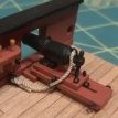
When I made the Pegasus guns I added the bolt that secures the cap square in place plus the key and chain.
005
050
These were at 1:64 scale, so replicating these fittings at 1:48 scale would be a doddle, - right, - wrong. I think going slightly larger is more difficult as detail becomes more apparent.
At this point I hit a sort of wall and have been fiddling around ever since my last post.
6274
These are the makings to complete the carriage furniture.
The capsquares, eyebolt hinges, and joint bolts are fairly easy.
It's making the key and attaching the chain that tests my sanity and patience to the limit.
The Chain is some tiny stuff I have in stock whose origin is now obscure. 48 links to the inch just about right for the purpose, but still quite tricky to attach to the key in particular.
Working out an approach and method is the first hurdle, handling the tiny little beggars is the second.
I have spent several days faffing around trying to fit these tiny additions, the chain links are so small that I have to seize them to the key and retaining eyebolt, using very fine wire, and the more the gun is handled the more the finish is affected.
6334(3)
From 12" normal viewing the result doesn't look too bad, from some angles anyway.
6335
The joint bolt fashioned from a cut down eyebolt, I am fairly happy with.
6329
Not entirely sure about the height of the key bolt or the size of the key, this is the area that bothers me most.
The difficulty is fashioning these in an even smaller size.
A further test is how does the finished gun look in place, no good doing it if it detracts from the look.
6344
6342
6349
Is the overall result worth the effort, I'm not sure and grow less so with the prospect of a further eleven guns to dress.
I will give it one last go before I start on any further guns.
B.E.
26/02/2019
-
 Beef Wellington got a reaction from Haliburton in HMS DIANA by Peterhudson - Caldercraft - 1:64 Scale
Hi Peter - planking is looking good, you handled that tricky area at the stern under the wale very nicely! Always hard to tell in the photos, but did you leave a lip for those few ports that will receive a lid at the bow and stern?
-
Beef Wellington reacted to RGL in SMS Seydlitz by Canute, Cog, Stein Gildberg & RGL - FINISHED - Hobbyboss - 1/350 - PLASTIC
Well, nearly done, the final cables and pulleys added. I want to rust up the nets some more then I can add the final anchor, strip the plastic wrap and await my colleagues
-
Beef Wellington reacted to RGL in SMS Seydlitz by Canute, Cog, Stein Gildberg & RGL - FINISHED - Hobbyboss - 1/350 - PLASTIC
Thanks OC. Last of the rigging, lines onto pulleys that pull out the booms from the hull and pull them back in, rigged to the capstan. Only a few hours to go now.
-
Beef Wellington reacted to Peterhudson in HMS DIANA by Peterhudson - Caldercraft - 1:64 Scale
I have been away for a few weeks; odd how work seems to get in the way of modelling but I suppose the joy of this hobby is that you can dip in and out, catch an hour here and an hour there which allows some momentum to be maintained. When I was last in the forum, I was mulling over whether to use Boxwood or Walnut to second plank the upper works of the ship - after much cogitation, I decided to go boxwood. Thanks to really helpful advice from Rob, I managed to secure some decent, none too yellowy, strips in two thicknesses (why is it so expensive?) which I have been slowly fixing to the hull. First I had to finish the Gun wales which were then painted. I agree with another contributor that the Admiralty paint leaves an excessive shine so will go over them very lightly with gunmetal black to town them down. I am not entirely content with the line - I tried to measure from the plans, I tried to align by eye, I mapped it to the waterline etc etc but it still seems a little low on the hull and seems to be a it distorted around the stern.
I will have to make do with this and when I get to the transom, think carefully at how I bind all this together - if I was doing it again, I would lift it about 5mm up and ignore the plans. I guess a little filler is going to be used. The stern areas sits, glaring at me; almost giggling 'wait until you get to my area!!' - so I will concentrate on the hull then look carefully at the rear section.
I have then been slowly sticking on second planks, needs to be done carefully but is very time consuming. I am learning the good and bad aspects of cyno glue....be quick to clear and sand off any excess. I am still not clear on lined and non lined gunports: once the second planking is complete I will return to the 4 unlined ports on each side and see what happens there!!
The box wood does looks good and once sanded, relevant parts painted and the rest sealed should be pleasing to look at. I now have to work out how to marry the differing wood thicknesses on the lower hull: boxwood 4.7 x 0.7mm; walnut 5 x1.0mm - I don't want a bulge when it comes to the copper plates; I guess sanding is the order of the day! I have begun tapering the planks around the rudder head and then down to the eventual waterline - this is another area where I suspect there will be joyless moments ahead!
Anyway here she is. I am reasonably pleased: taking my time and thinking very carefully before I commit anything to glue.
Peter
-
 Beef Wellington got a reaction from popeye the sailor in La Renommèe by Landlubber Mike - Euromodel - Scale 1:70
Looking good Mike, I find making up gratings tedious but somewhat satisfying and glad it worked out for you. I have to admire your commitment to painting with wood, especially in a kit, and suspect it takes longer to customize satisfactory solution that building from scratch.
-
 Beef Wellington got a reaction from JayCub in HMS Snake by Beef Wellington - FINISHED - Caldercraft - Scale 1: 64 - First wooden ship build
Cheers Jim and the likes, and thanks Mort - unfortunately I'm way beyond that decision but something to think about for the future...
Rigging seems to be a little bit of a neglected area on this site, so wanted to post few pics of progress, for things specific to this kit where may be of help to others and also to hopefully capture where I've deviated from the plans. Petersson has been INVALUABLE!
As a side note, I also nearly had a heart attack when I brought Snake outside for a few photos - I normally work in artificial light in my basement, and the natural light made all sorts of sorts of previously unseen 'fuzzies' VERY apparent. I vow never to use kit supplied line again, but am committed to making it work here for consistency. Will probably try brushing on some dilute PVA to try to tame them at some point.
I've found the following 3 scenarios to be common:
Plans are not clear - in these cases I've tried to follow Petersson Plans are clear enough and are somewhat consistent with Petersson - in these cases I've followed the plans but tweaked in some cases where it seems to make more sense Plans are clear enough, but differ from Petersson - in these cases I've followed the plans, unless Petersson seems more logical/elegant.
Foreyard and Fore Topmast
Fore yard prior to installation. Jeers and slings also pre-rigged
Foremast installed. I used thicker line on the jeers (.75mm) as this seemed more in keeping with pictures I've found and attached round the yard following Petersson. As expected, I found lashing the slings rather challenging.
I found the trusses could be made following plans and Petersson, but was the devil trying to get in place with all pendants and catharpins. Truss in place (sorry picture is little blurry), I did not even attempt to put in the knave line!
Fore-topmast in place. Found the parrals very fiddly to do, but they can be done according to Petersson. I gave the parral beads a couple of goes in the drum sander to take off the shine and it gave a very pleasing result.
The fore-topsail yard tie and lifts were taken around the fore-topmast with an eye splice as per Petersson.
Belaying items for the foremast is rather challenging on Snake as the for'd bits are very close to the platform and leaves very little room for maneuver. I also didn't make this any easier by belaying the hawsers around the bits either.
And finally, where things stand currently...I added flemish horses to the fore-topsail which are not identified in the Snake plans, but seem pretty ubiquitous and covered in Lever.
-
 Beef Wellington got a reaction from Jonny 007 in HMS Snake by Beef Wellington - FINISHED - Caldercraft - Scale 1: 64 - First wooden ship build
...and the result with the new bow grating angle.
I lost the close up photo, but one thing you can just see in the bottom picture was the enlargement of the slots for the gammoning. As supplied, these slots were not long enough to allow the gammoning to be done properly but it was pretty easy to extend these using a needle file.
-
Beef Wellington reacted to AlexBaranov in Standart 1893 by AlexBaranov - FINISHED - scale 1:48 - Imperial yacht
Read it ready
-
Beef Wellington reacted to Hubac's Historian in Soleil Royal by Hubac's Historian - Heller - An Extensive Modification and Partial Scratch-Build
Painting the port lids has been a process, but it has yielded some pretty good results:
I used a translucent red/brown wash from War Hammer to get into the creases and the lows of the gilded ornaments for better contrast. The difference is subtle, but worthwhile:
Here are a few shots of them placed, to get a sense for what that will look like. When it actually comes time to install them, I will make up lanyard rings:
While I was at my father’s, this past weekend, I picked up the gun barrels for the middle battery. Previously, I was puzzled as to why I only had 24 out of what Should have been 32 lower battery guns - what Heller is designating as 24 pounders.
Well, it turns out that the kit researchers were also aware of the practice of a mixed armament on the lower deck; for the kit, the aft four guns on each broadside, as well as the four stern chase ports are designated for 18 pound guns. The middle battery are all 18 pounders.
For the record, Heller’s classification and distribution of the armament is lighter, overall, than what the ship carried in reality; for example, the lower battery was a mixture of 36 and 24 pound guns, with - if I remember correctly - the majority being the lighter 24s.
This discrepancy between the model and the reality bolsters my decision to beef up the gun barrels from the lower deck, on up.
Right now, I am replicating the same process of adding an insert for 6 of the 18 pound guns; I may leave all four of the stern chase ports empty, or I may arm the two closest to the rudder. I haven’t yet decided.
I will take one 18 pound gun barrel, and attempt to make castings for the entire middle battery. For my casting blanks, one half will already have the insert glued and faired, in place. To facilitate casting, I will cut away the dolphin “handles”, which wouldn’t be visible, anyway. I had remained hopeful that maybe I saved the 24-pounders from my first build of this kit, but I couldn’t find them anywhere. They must have been a casualty of several purges.
One thing that I have begun to ponder more seriously is what, exactly, I will do about the quarter galleries. Although, I still think that the following drawing originated from the hand of Jean Berain, there are certain problems in its presentation that need to be resolved:
The biggest issue has to do with the five windows shown in the closed middle deck tier - the functional toilet of the officers’ quarters; first of all, the windows taper down in size from aft, moving forward. Second, of all, this profusion of glass (whether dummy windows or actual glass) clutters the design. Thirdly, the diamond-hatch webbing does not correspond to their corollary on the stern.
Resolving these issues will necessitate sketching them out. I started to do this on the computer, a couple of years ago. I managed to get the amortisement mostly done, before the software locked up:
So, I will sketch out the lower section of the QG by hand.
I have this idea that I can take cues from the following Berain scheme for the Formidable to help simplify and de-clutter my new quarter galleries. The Formidable was an Etienne Hubac built ship from 1691, and as such, a very near contemporary of the re-built (also by E. Hubac) Soleil Royal:
There is nothing, in my view, about this scheme that seems out of place or proportion. My main approach, here, would be to reduce the four primary windows down to three, with better spacing and more consistent scale. This will also simplify all of the fleur-de-lis paneling, beneath that. I may, also, eliminate the smallest fifth window, replacing it with a simple panel, and perhaps an appropriate ornament - the criss-crossed L monogram, for example.
My first attempt at making this lower section will probably involve carving the complex, faceted form from close-grained solid wood, to which will be added moulding and paneling and carvings.
I had tried to do some experiments with polymerized clay, but I’m a long ways off from Doris. I at least understand how wood behaves and how to shape it.
In other research news, I have struck up a very interesting and informative correspondence with Montreal native Guy Maher. Guy is another SR obsessive, like myself, who has assembled a really impressive body of research into Soleil Royal’s early appearance.
There is much that he and I agree on, but naturally we have our different views about certain things. At the moment, I am reading through one of his primary sources:
Mr. Dessert is a modern historian with a particular interest in the life and times of Louis XIV, and the ministers of his empire. He has a number of titles to his credit, concerning this epoch. This book, so far, is an excellent overview of all of the individual strata of Human Resources that made Colbert’s navy possible. There promise to be a few golden nuggets about SR that may corroborate or refute some of what I’ve presented here, so far. Either way, I remain open to the possibilities.
One fascinating observation from Mr. Maher, so far, is that the following drawing of the head (which also clearly appears to be Berain’s hand) makes no allowance for the actual structure of the forecastle deck. There is only a forward sheer railing, just over the main deck ports, but no additional “step” above them to include the structure of the forecastle deck:
I am almost absolutely certain this is Berain’s hand because on the French modeling site, where Michel Saunier primarily posts his SR build, Gerard Delacroix posted very clear close-ups of this drawing. Their style of line and shade exactly matches that of the Berain stern drawing.
We know, absolutely, that SR always had a forecastle. Are we to believe that Jean Berain “forgot” to include this detail? As many times as I have looked at this drawing, I have never noticed this discrepancy. But, there it is! I have no theories or explanations for that one.
Tanneron did not forget to include this step-up to the forecastle deck:
As it was drawn, though, it would be as though the waist rail merely continued all the way to the headrails. Perplexing!