ziled68
-
Posts
158 -
Joined
-
Last visited
Content Type
Profiles
Forums
Gallery
Events
Everything posted by ziled68
-
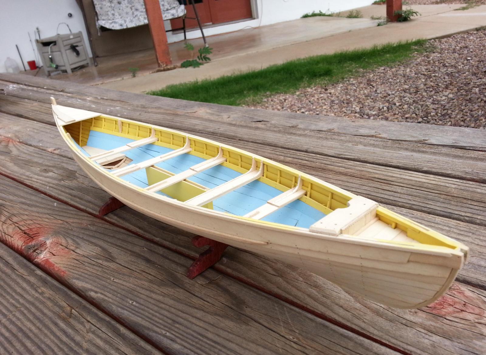
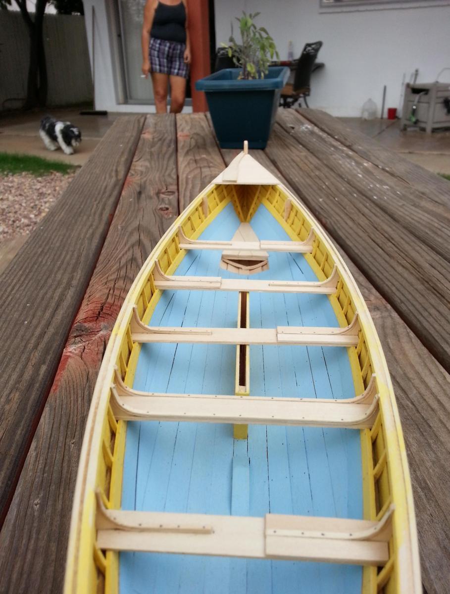
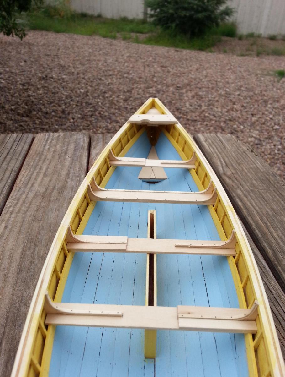
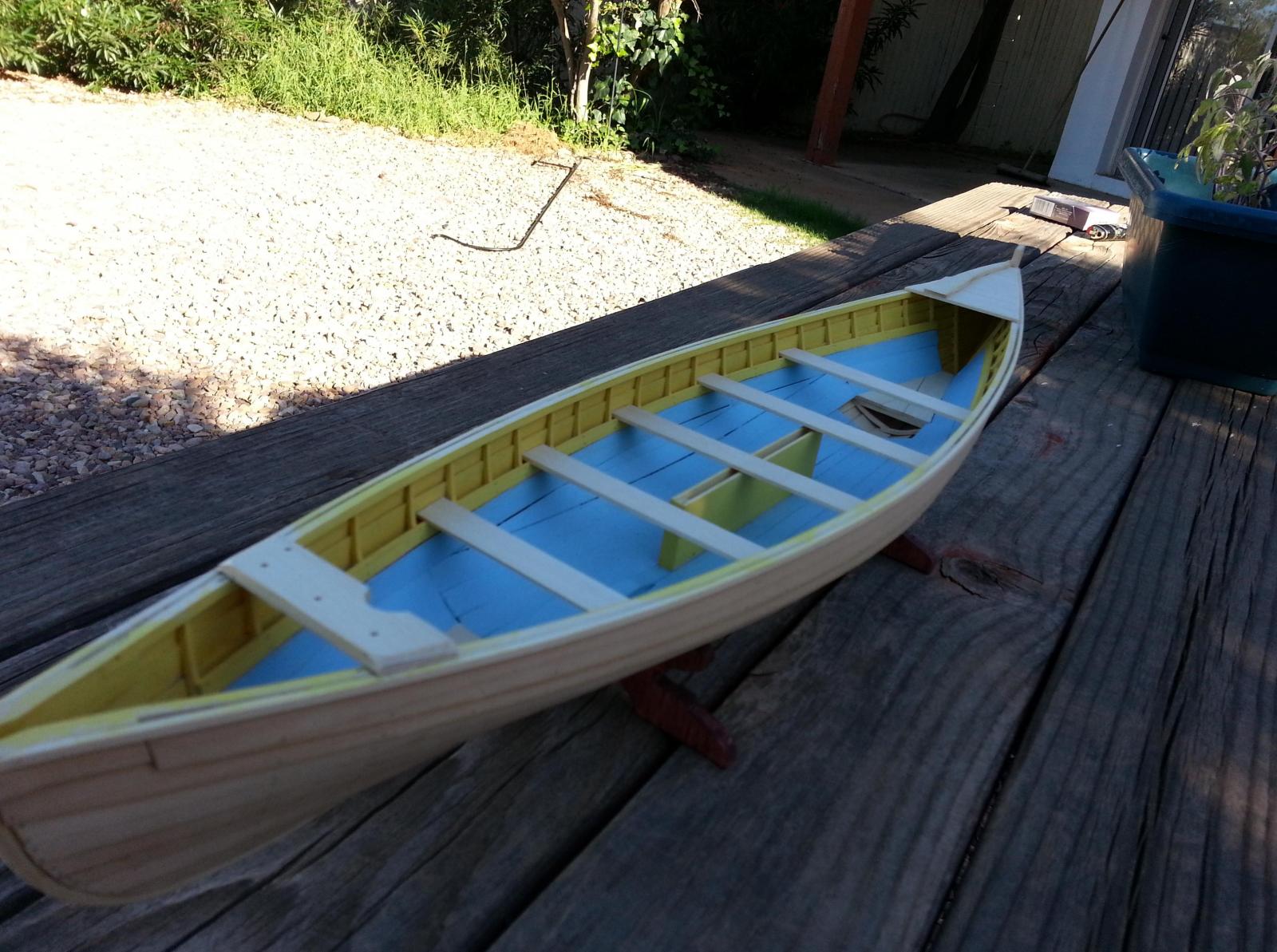
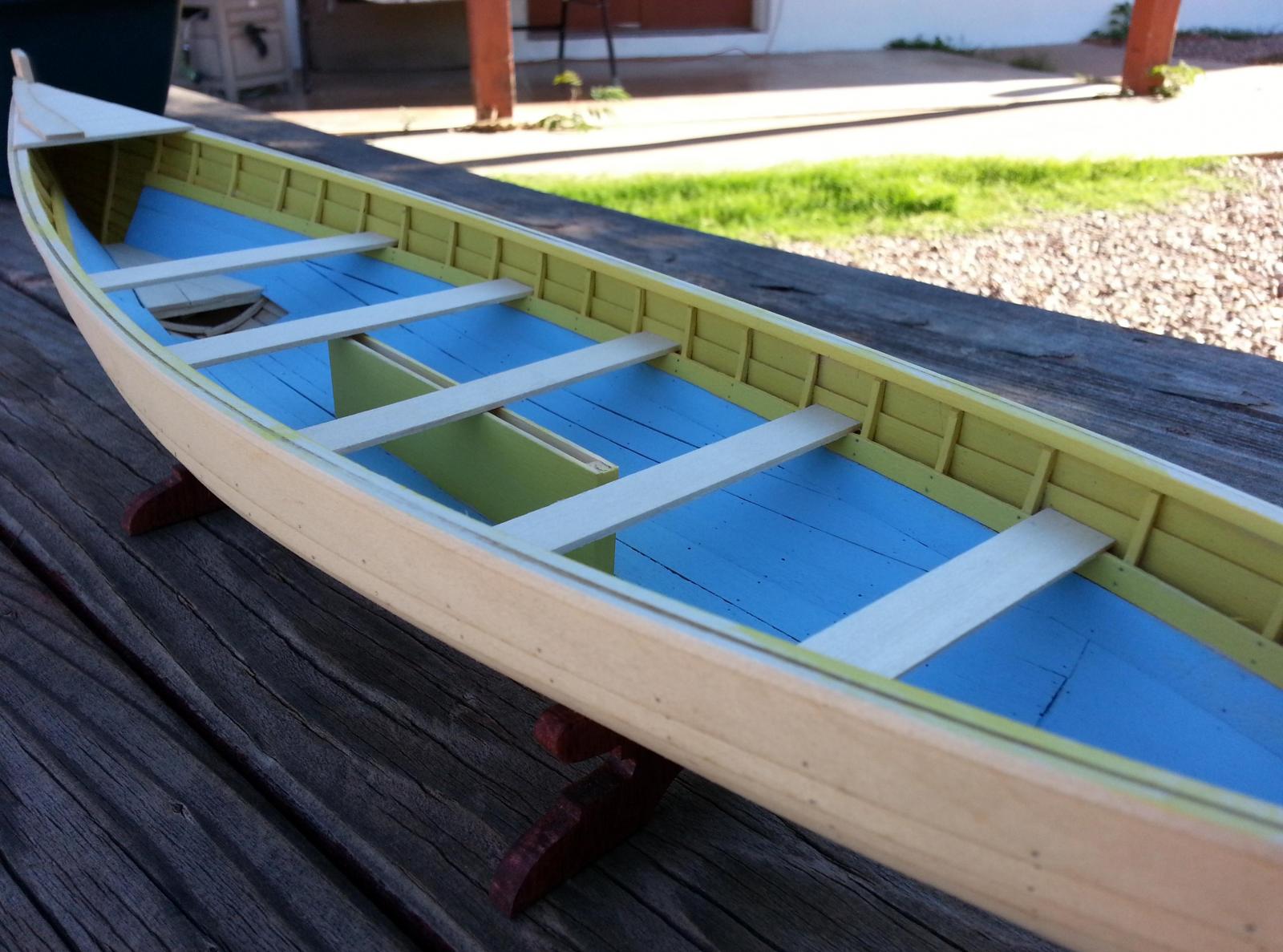
 Hello everyone, It’s been slow going since my last post but one that had to be done to get great results. I added the rubbing pieces outboard, just below the gunwale strakes. The guide states that this piece is made from 1/16” x 1/8” timber which I believed did not do justice for this important and noticeable aspect of the whaleboat. I decided to use the 1/8” x 1/8” timber I used as a retaining batten when I separated the form from the horses. I used the measurements from sheet 1 of the plans and tapered the ends to its specification. After completing the rubbing pieces, I started working on the thwart knee filler blocks. These filler blocks are a simple affair but extremely time consuming if you want it to look great. Once the filler blocks were installed, I went through the procedure of steaming1/32” x 1/16” timber to form the thwart knees which is a laminated procedure similar to the frames for the whaleboat. As I finished up one set of thwart knees I immediately added pads to the areas mentioned by the plans. I finally put the week to an end via the construction of the box just forward of the thigh board. Once complete. I went back and went through the procedure of adding all my simulated tree nails to the areas that required them. The following photos will show you how she is looking. Ray


- 31 replies
-
- 5
-

-
- new bedford whaleboat
- model shipways
- (and 1 more)
-
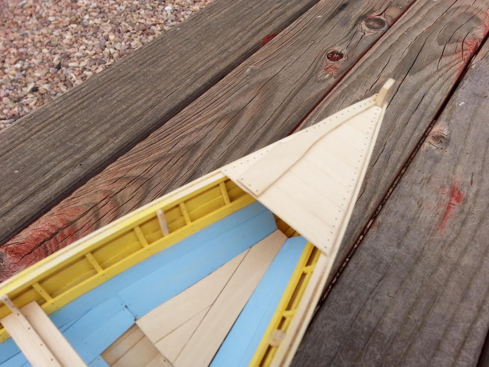
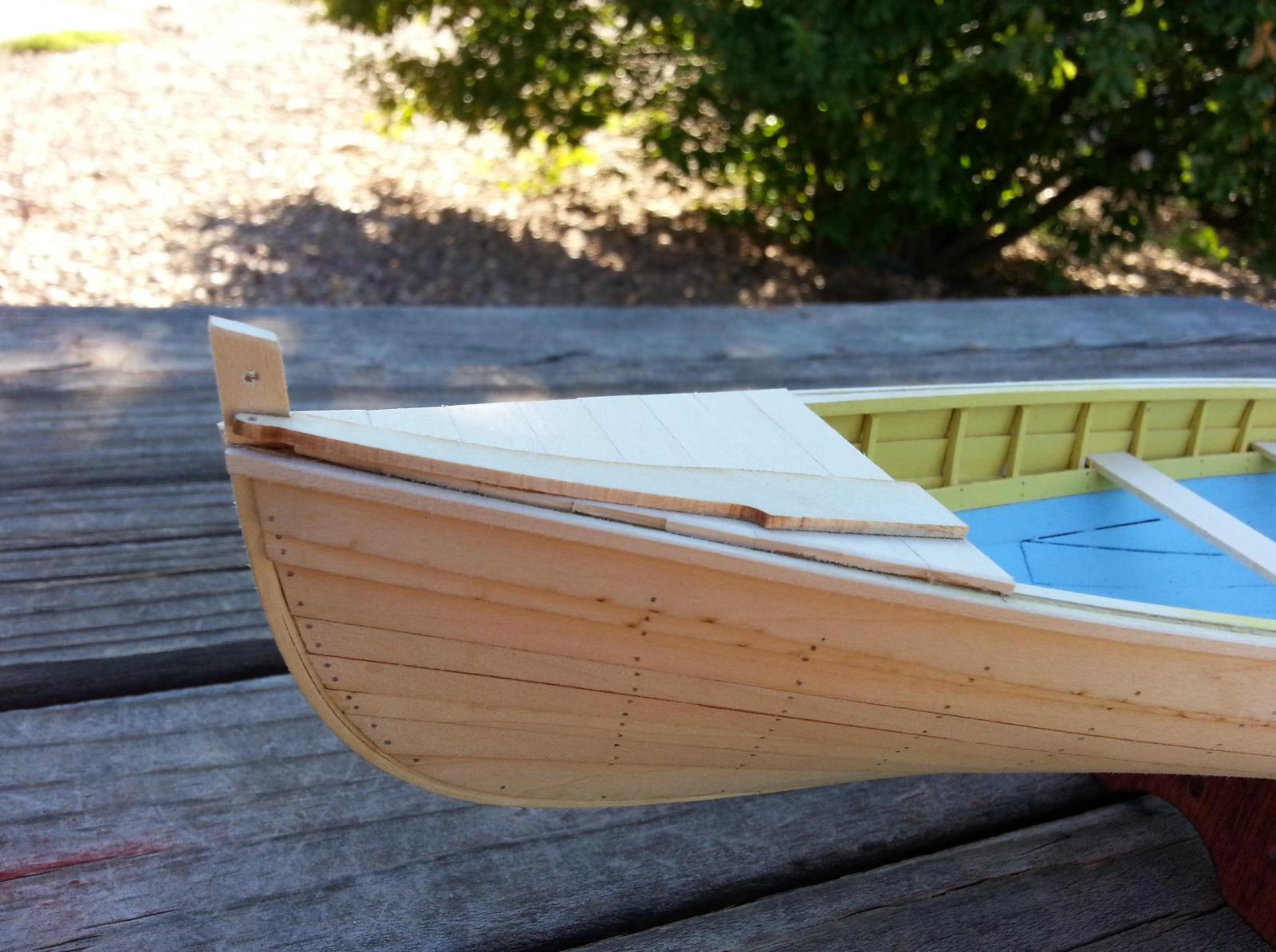
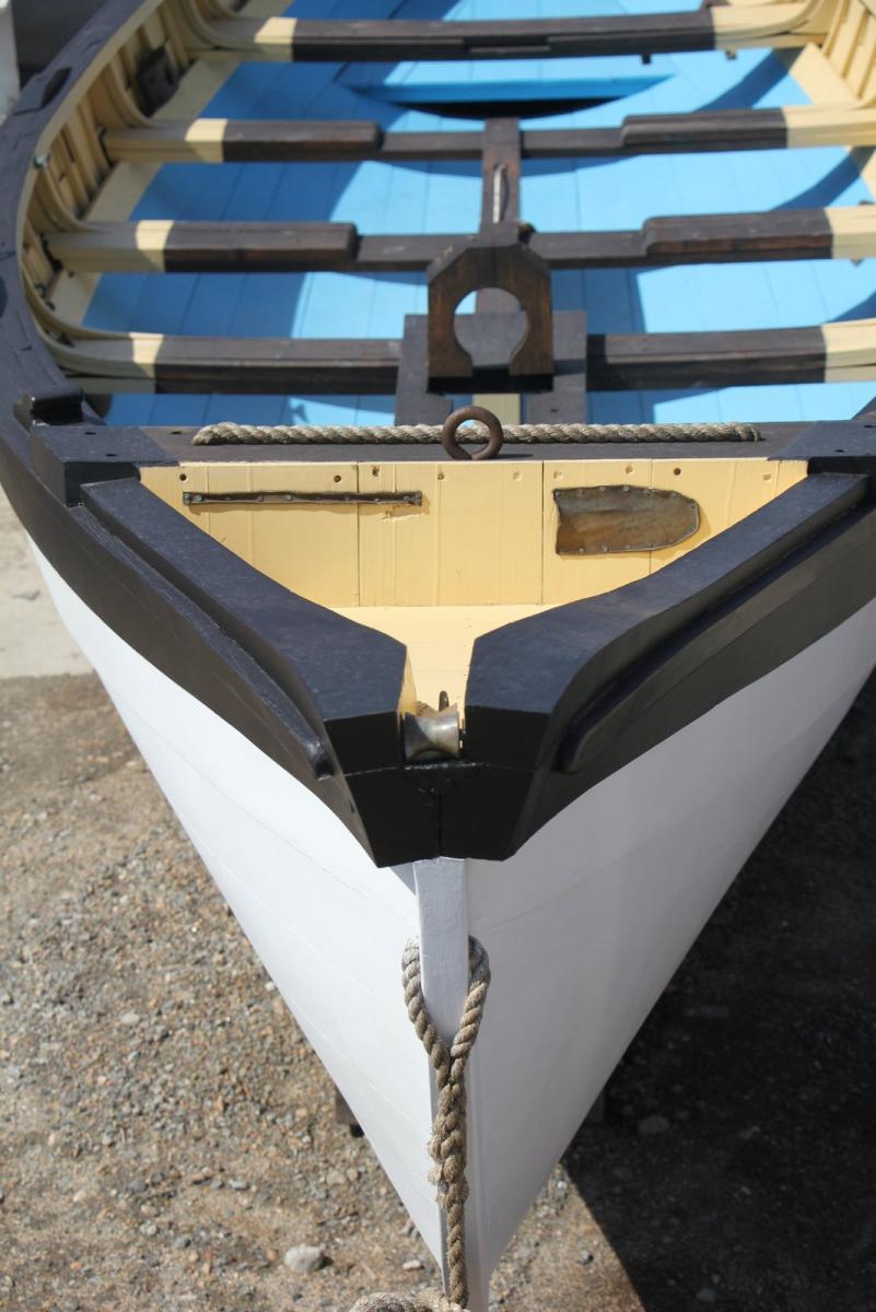
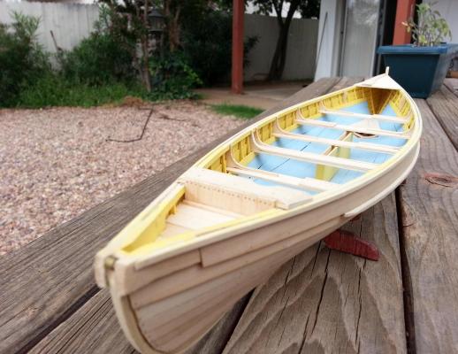
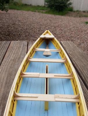
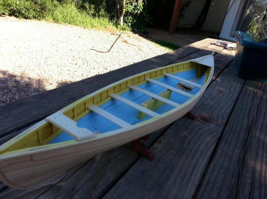
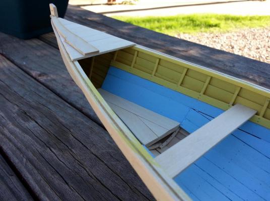
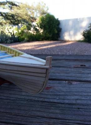
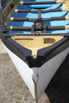
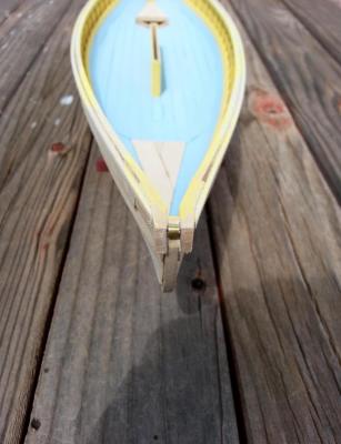
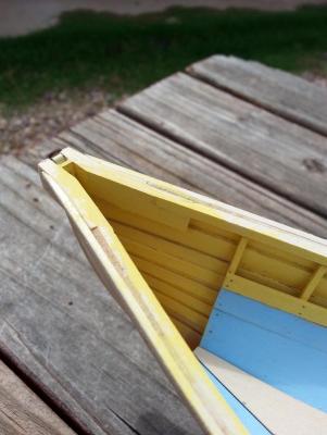
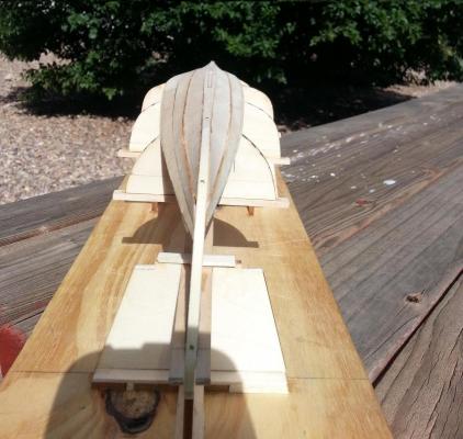
Hello Everyone, The newest progress to my whaleboat is the addition of thwarts, thigh board, cuddy board, and lion’s tongue. The thwarts were an easy addition to my whaleboat via getting a rough dimension of the size per thwart and using scrap timber to get the correct angle for the sides. The inwale will tend to impede progress a bit but is not really an issue. The guide states that the thwart risers are notched slightly so as for the thwart to have better contact. An interesting tidbit of information in regards to these notches was that it was done as a “cure” for thwart risers that were fitted to high on one or both sides. The thigh board was next on the butcher block which was a simple affair to work on. The guide states that you should get the width of your thigh board from the model itself rather than the plans due to the fact that the bow may have tapered more than expected. It also states that if you have not already added nails to your model, you should at least nail the thigh board down for added strength. What I did was add a bead of carpenters glue followed by small dabs of super glue to where the thigh board will rest and finally place the thigh board on the gunwale. The cuddy boards and lion’s tongue followed similar fashion as the thigh board with one exception. The stem post that protrudes above the cuddy boards were laminated strips of timber. At the beginning of its construction, the guide made no mention that this area had to be longer so I made it long enough to where I believed it had to go. Bad idea. Since I was not happy with it, I had to perform a minor operation to remedy this fiasco. I am now one happy camper. The following photos will show how she’s coming along.


- 31 replies
-
- 5
-
-
- new bedford whaleboat
- model shipways
- (and 1 more)
-
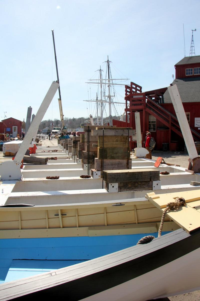
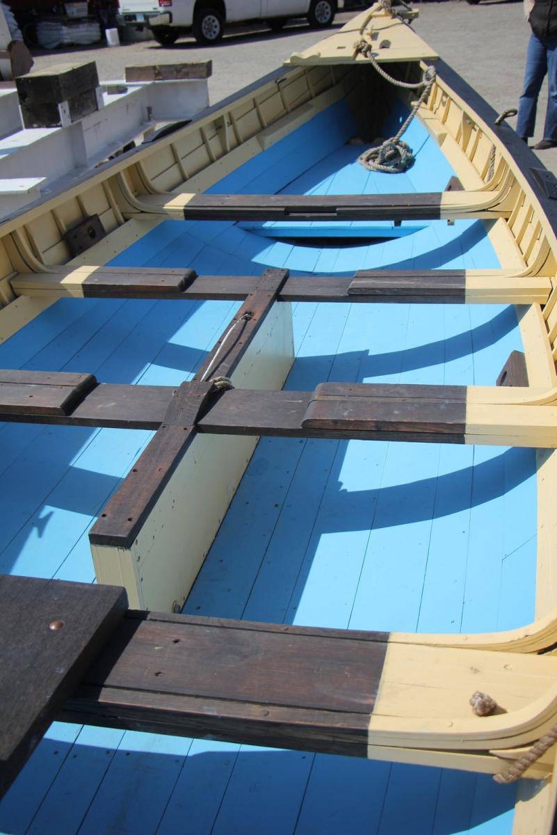
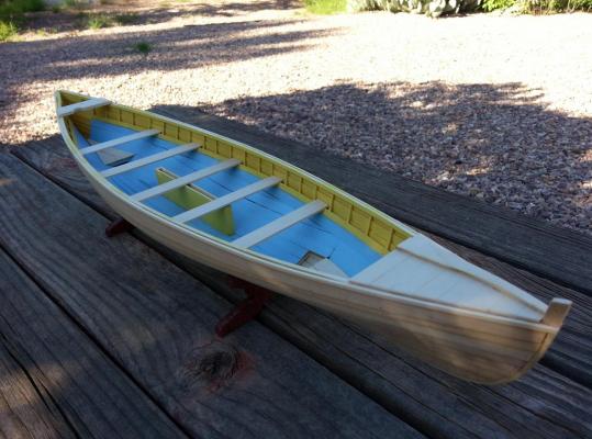
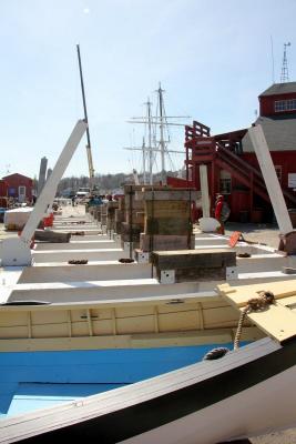
Thank you Curtis, I hope that my build will give you inspiration for your build. Hello Everyone, The latest progress to my whaleboat is in the form of cheeks, inwales and gunwales, and paint. Well for starters, the cheek pieces were a little difficult due to the fact that you only get overall dimensions for them but not how to go about it. This is where your artistic abilities come into play. The rough dimensions of the cheeks are 1/” x 3/8” x 1 ½”. The guide is where you will get a better feeling for the construction of the cheeks so pay attention to it. Once completed, I added the cheeks to the stem and realized that I had not placed brass roller between the cheeks. It was a simple affair to address via cutting the 1/8” brass tube filling it with a wooden dowel and passing a pin through it to hold it in place. After the cheeks were installed I worked on both the inwales and gunwales. These are pretty straight forward but I must say the gunwales that lie against the cheeks must be sanded to follow the cheeks profile. Upon completion of these items, the guide states that if you wish to paint your whaleboat, now is the time to do so for the interior of the boat. As for choosing a paint scheme that would give my whaleboat any justice, let’s just say that I suck at it and did some research online. I came across this website, http://www.muffyaldrich.com/2014/04/charles-w-morgan-launch-minus-23-days.html, which talks about the preparation of Mystic Seaport’s Charles W. Morgan. After reading and looking at pictures, I came across its whaleboat and was immediately drawn to its color scheme which I will follow as best as I can. The following photos will show how she’s coming along (keep in mind that the first three are of the Morgan’s whaleboat).

- 31 replies
-
- 5
-
-
- new bedford whaleboat
- model shipways
- (and 1 more)
-
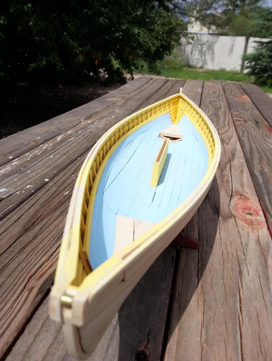
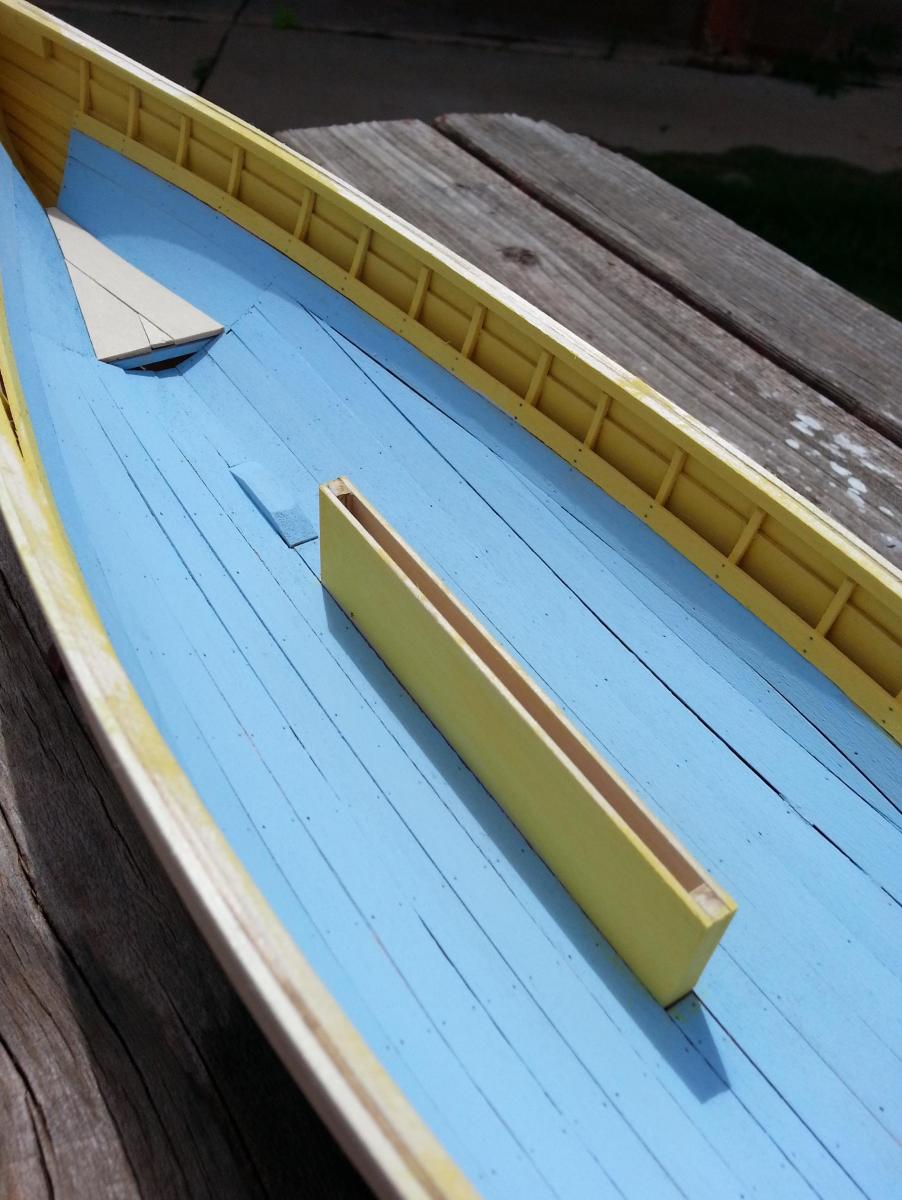
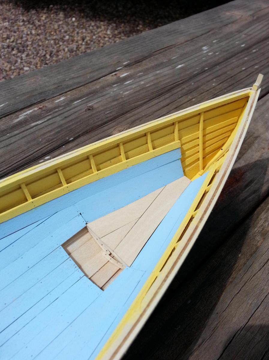
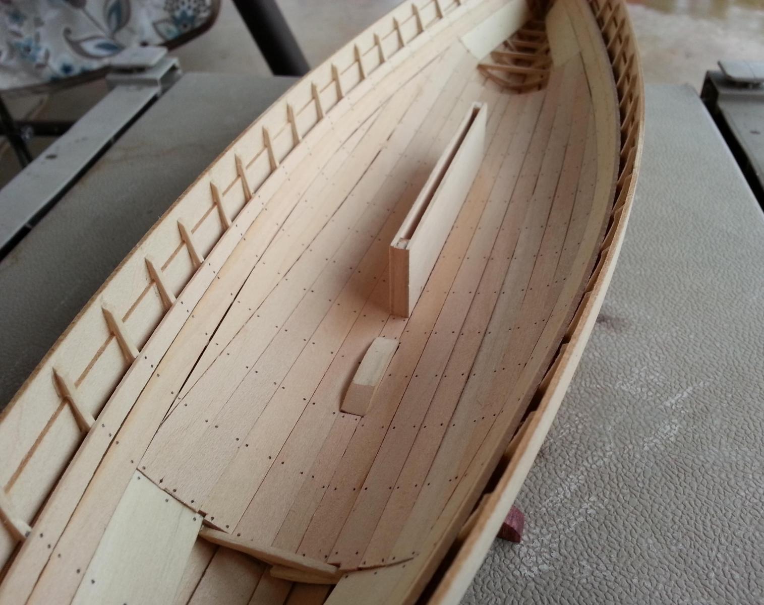
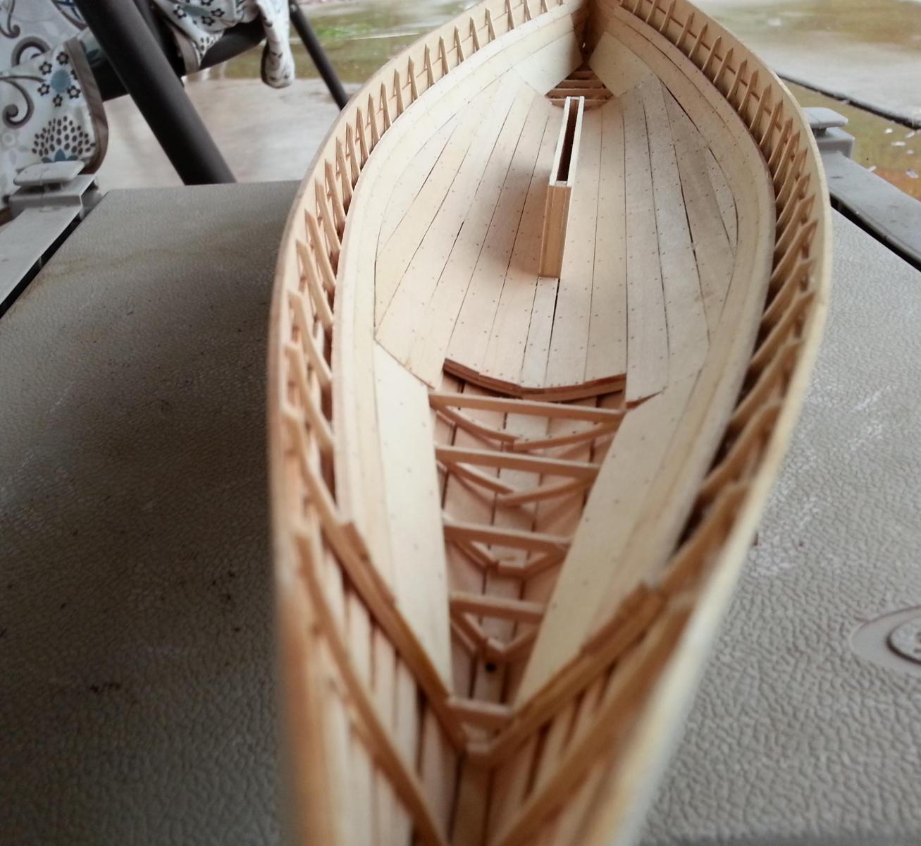
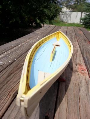
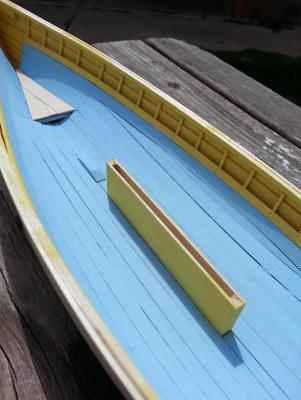
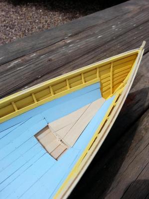
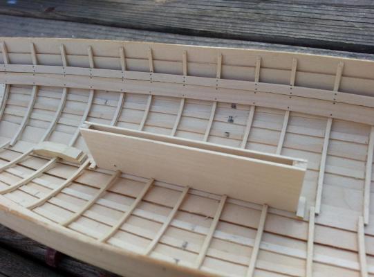
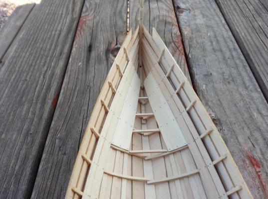
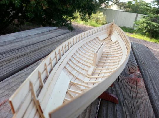
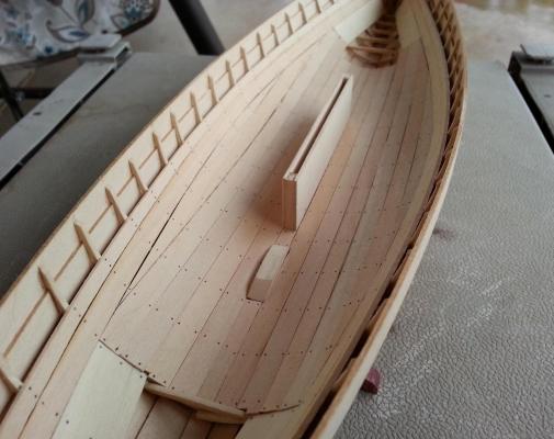
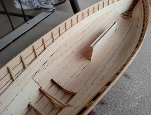
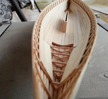
Hello Everyone, As promised, here is the latest update to my whaleboat. The plans and guide state that the first strake to be placed inboard is the thwart riser followed by the adjacent ceiling. Care must be taken to ensure that the thwart riser is 5/8” below the gunwale between stations 1 ½ and 4 ½. Forward and aft of these point the measurement is 11/16” giving it a gradual slope. The thwart riser starts from the most forward most frame and will continue aft up to the second from the last frame. Once you have placed the thwart riser, it is time to tackle the adjacent ceiling. The adjacent ceiling needs to be trimmed and/or sanded to get a nice tight fit along the thwart riser. Also, you will have to cut and install short wide pieces which cover the frames at the bow and stern. Once that is complete you can go ahead and trim the slot along the keel to accommodate the centerboard trunk and mast step. The plans are nicely drawn and it is a simple process of getting the measurements for both of these items. Now I must point out that the height of the centerboard trunk is level with the thwart riser. I found it easy to add a strip of timber from the port thwart to the starboard thwart and use that as a guide to get the correct measurement for my centerboard trunk. Now before you glue it into place, make sure that you bore the pivot hole for you centerboard. The mast step is a simple affair so I’ll not go into it with the exception of pointing out that you will not bore the mast hole for it at this time. Since it was raining today, I had plenty of down time to concentrate on the deck’s ceiling. I started the first plank near the centerboard trunk and work outwards. The first 4 ceiling planks are easy due to the fact that they only receive a 90 degree cut at their ends. The fifth and sixth planks are a little more time consuming because they have extreme angle that need to be cut just so. After the installation of each ceiling, I marked my boards where the simulated treenails would be placed above each frame. The following photos will show you how she’s coming along.

- 31 replies
-
- 6
-
-
- new bedford whaleboat
- model shipways
- (and 1 more)
-
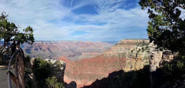
Greetings to all, Well this past Labor Day weekend I did not do anything to my whaleboat so the progress that I have to report is small so I’ll post them tomorrow. On the other hand, I did go to the South Rim of the Grand Canyon with my wife and just enjoyed my time off to take in the sights. I want to share the following pictures with all of you and I hope you enjoy them as much as I did.


- 31 replies
-
- 3
-
-
- new bedford whaleboat
- model shipways
- (and 1 more)
-
Hola Mija, I was just going over your latest progress and Bravo to you. I especially like the ships ladder attached to the port davit amidships. Would it be possible to take a few shots of the ships hold from different angles? I hope to see more of your build. Tu Amigo, Raymond
-
Hey Al, I was thinking of your problem with not get the eyebolts dark enough. Did you try using a propane torch on them? Just get the eyelet red hot and then submerse them in ice water. It's the same thing they do when they forge/make horseshoes. It's just a thought Kemo-Sabe. Ray
-
Hey Al, How are you Buddy. It's been a dog's age since I last heard anything from you. I was starting to worry that you've given up the ship. At this size, your eyebolts and rings will come in nicely. Hope to see more of your work. Ray
-
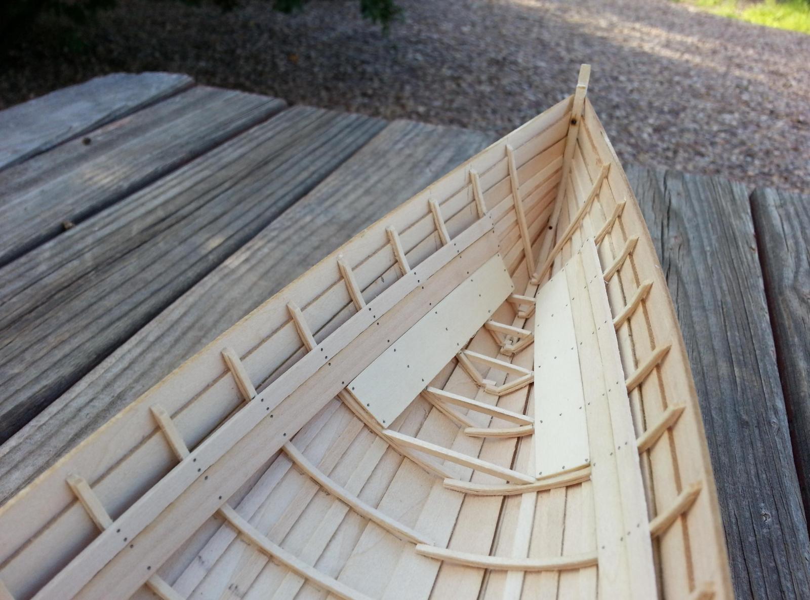
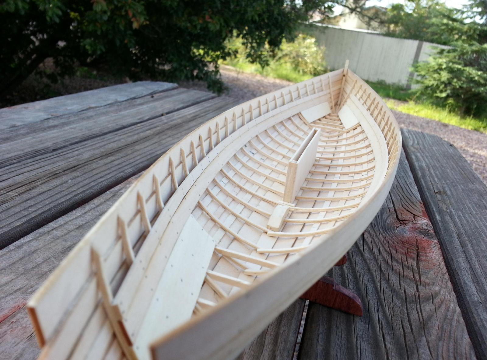
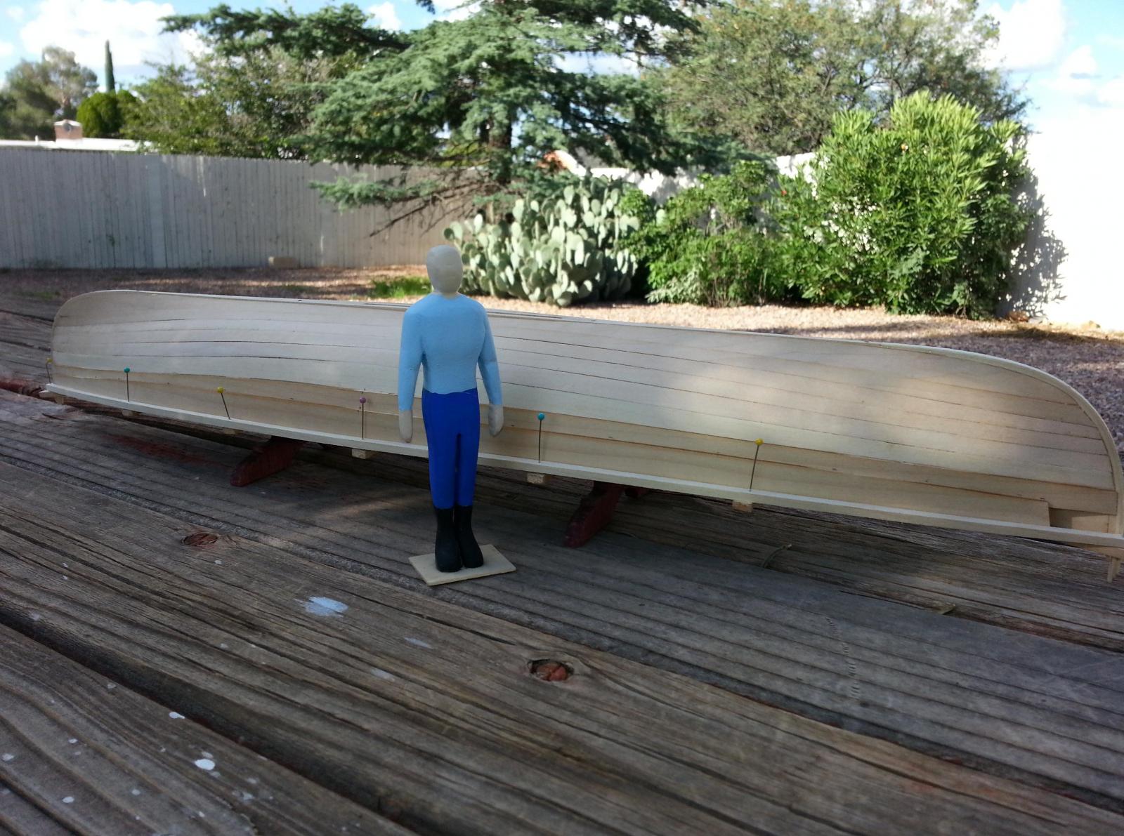
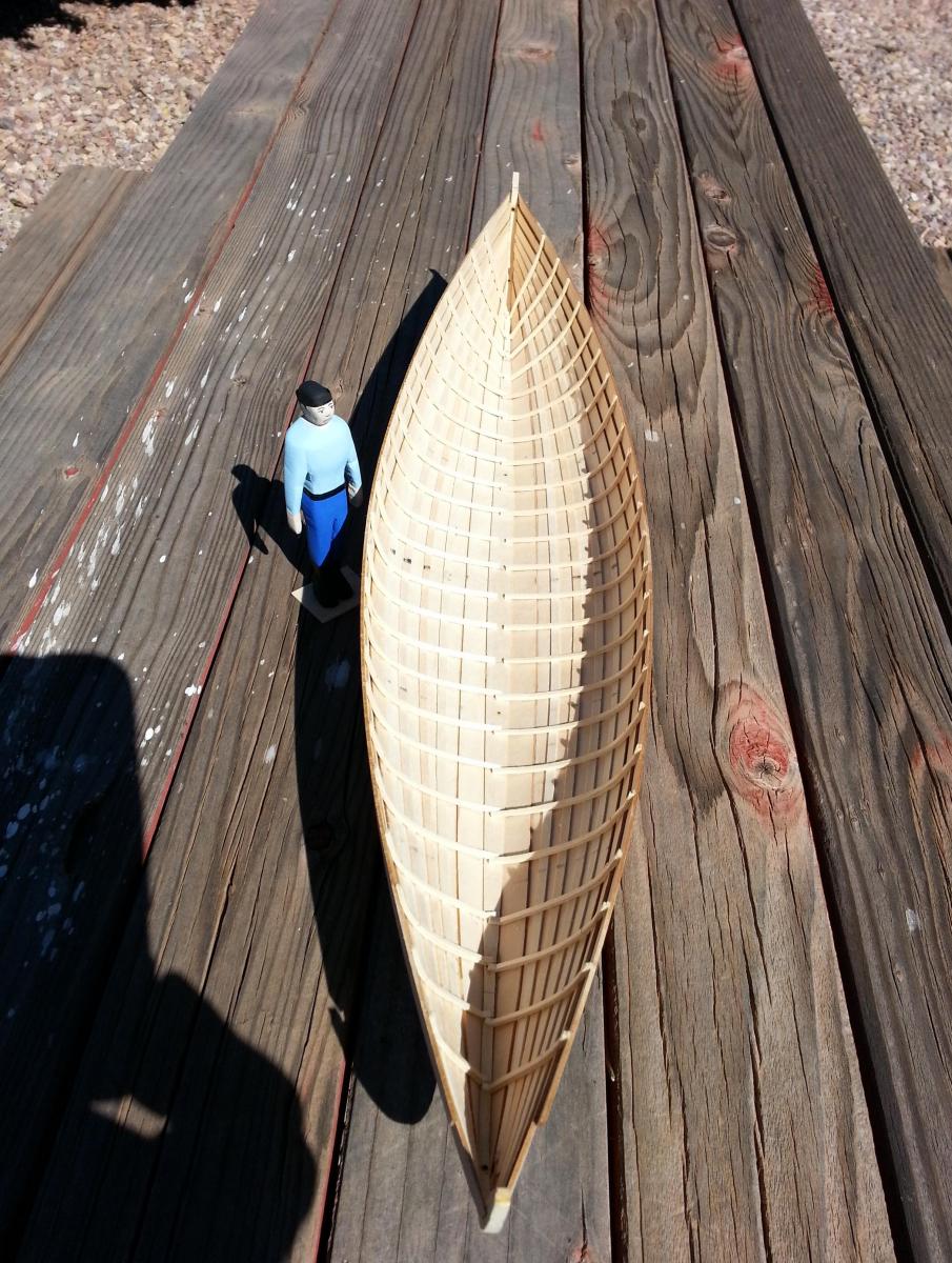
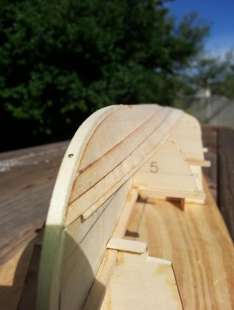
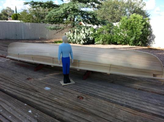
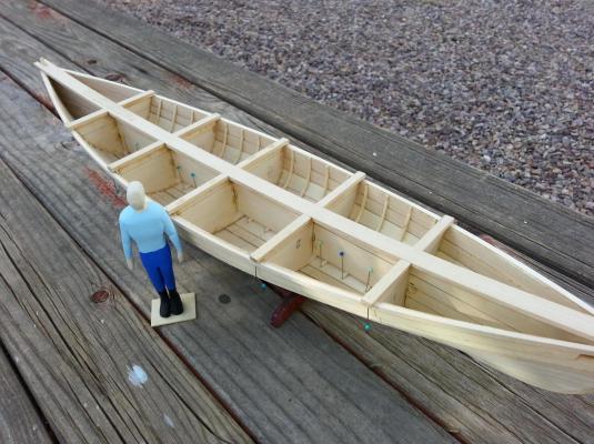
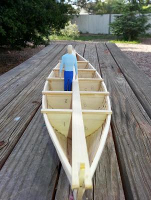
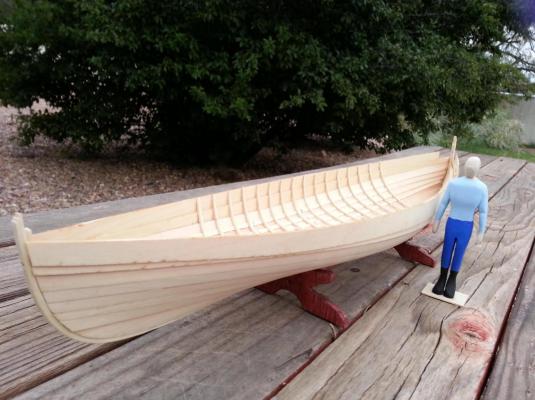
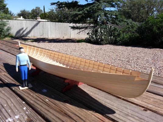
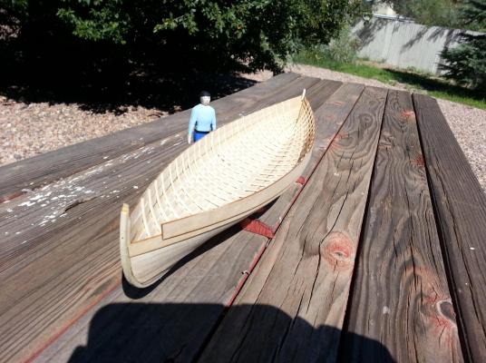
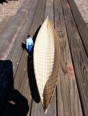
Hello everyone, I realize it’s been a while since my last post so let’ me see if I can bring you all up to speed. I last left off adding the strakes and batten seams to the form. I continued this process until getting to strakes 5 and 6 where these strakes need to be cupped to follow the contour of each section mold. The process is pretty simple in which you can either wet or steam these strakes attach it to a 5/8” x 5/8” quarter round molding and clamp in place until dry. Once dry, you add these strakes to your form. After the sixth strake the strakes no longer butt up against each other but start to lap. This can be seen when it is time to work on the sheer strake that needs to be completely beveled with the last inch heading towards the bow. Once the sheer stake is glued in place it is time to start working on the gunwale strake. You will notice that the gunwale strake is 1” shorter that the sheer strake due to the fact that gunwale strake will be placed 1” from the bow. Once your strakes have been given enough time to dry, it is time to pin the temporary retaining batten to the cap strip to protect your gunwale from harm. Once the retaining batten is in place, you can now remove the hull from the horses. Removal is really simple. All you do is pry off the gluing tab that holds the jig to the bow and stern horses. Once done, you score along jig and the amidships horse to separate it. Once the hull is separated, you can now go through the process of using the mold forms and a compass to draw your lines for your frames. You will get your measurements from the “Plan Views – Inboard Construction” on sheet 2 of your plans. The laminated frames are a simple process of steaming your frames, pinning it in place until dry, and finally gluing them in place. I’ve also had enough time to carve up a scaled man to show relative size of the whaleboat. I my carving of a man to be 5’ – 8” tall and at this scale he came out to be 4 ¼” tall. I also could not help but notice that he had a barrel chest making him look like a tank hence being dubbed “Hank”. The following photos will show you how everything is coming along.
- 31 replies
-
- 7
-
-
- new bedford whaleboat
- model shipways
- (and 1 more)
-
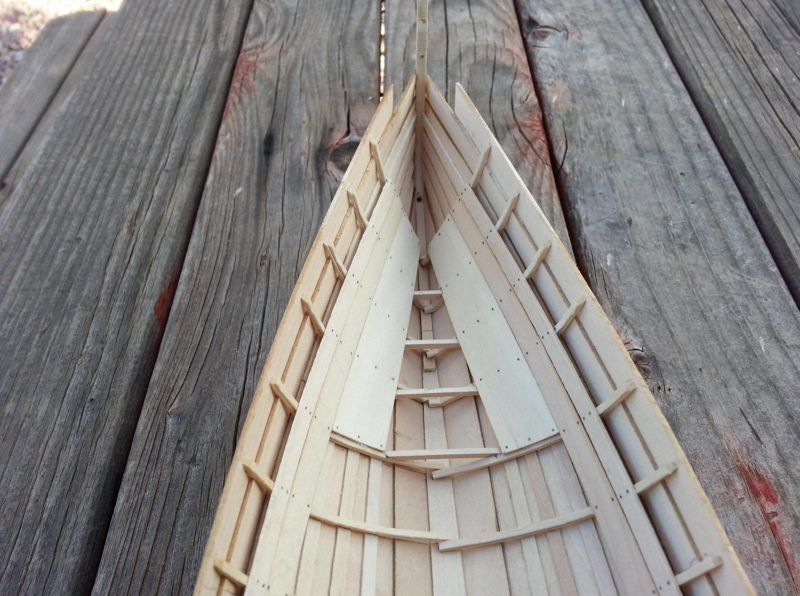
Greetings to all, Upon completion of the bow post, stern post, and keel it was time to add the garboards along the keel. Care must be taken into account when dealing with the garboards. First you will have to bevel the garboard section that rests along the keel. It is crucial to properly support the garboard on a thicker board when beveling so as not to accidently snap your garboard. Once you are happy with the bevel along the keel it is time to bevel the opposite edge of said garboard to accept the first strake which must overlap the garboard by 1/16”. Once the bevels are done, it is time to dry fit the garboard along the keel to ensure you are happy with the seam. If not, now is the time to tweak the bevel so as to get a tighter fit. When you are finally satisfied, it is time to glue the garboard in place. This is where my wife’s fabric steamer comes into play again. The garboard will rest flatly along the section molds but will drastically bend almost 90 degrees along the bow and stern posts. I steamed these sections for approximately 40 seconds, placed the garboard back on the form and held it in place with rubber bands until dry. Once the bow side of the garboard was done I tackled the stern side and repeated the same procedure. Afterwards, it’s just a matter of time to allow it to dry and glue onto the form. The first strake is the first one you will need to bevel until you get to the sixth strake which I’ve not come to yet. After the first strake has been added to the model, subsequent strakes are joined to it with a seam batten beneath. In the event you are not comfortable gluing these sections over the section molds, it is recommended to use paraffin wax on the section molds to avoid accidently gluing your model to it. The book actually states that once the strake has been glued down, it is time to add the seam batten by lifting the strake slightly to accommodate the seam batten. I found it easier to pin the seam batten on the section mold and glue the strake to the previous seam batten and the new one. I’ll continue this process until I get to the gunwales. The following three photos will show what I have thus far.

- 31 replies
-
- 2
-
-
- new bedford whaleboat
- model shipways
- (and 1 more)
-
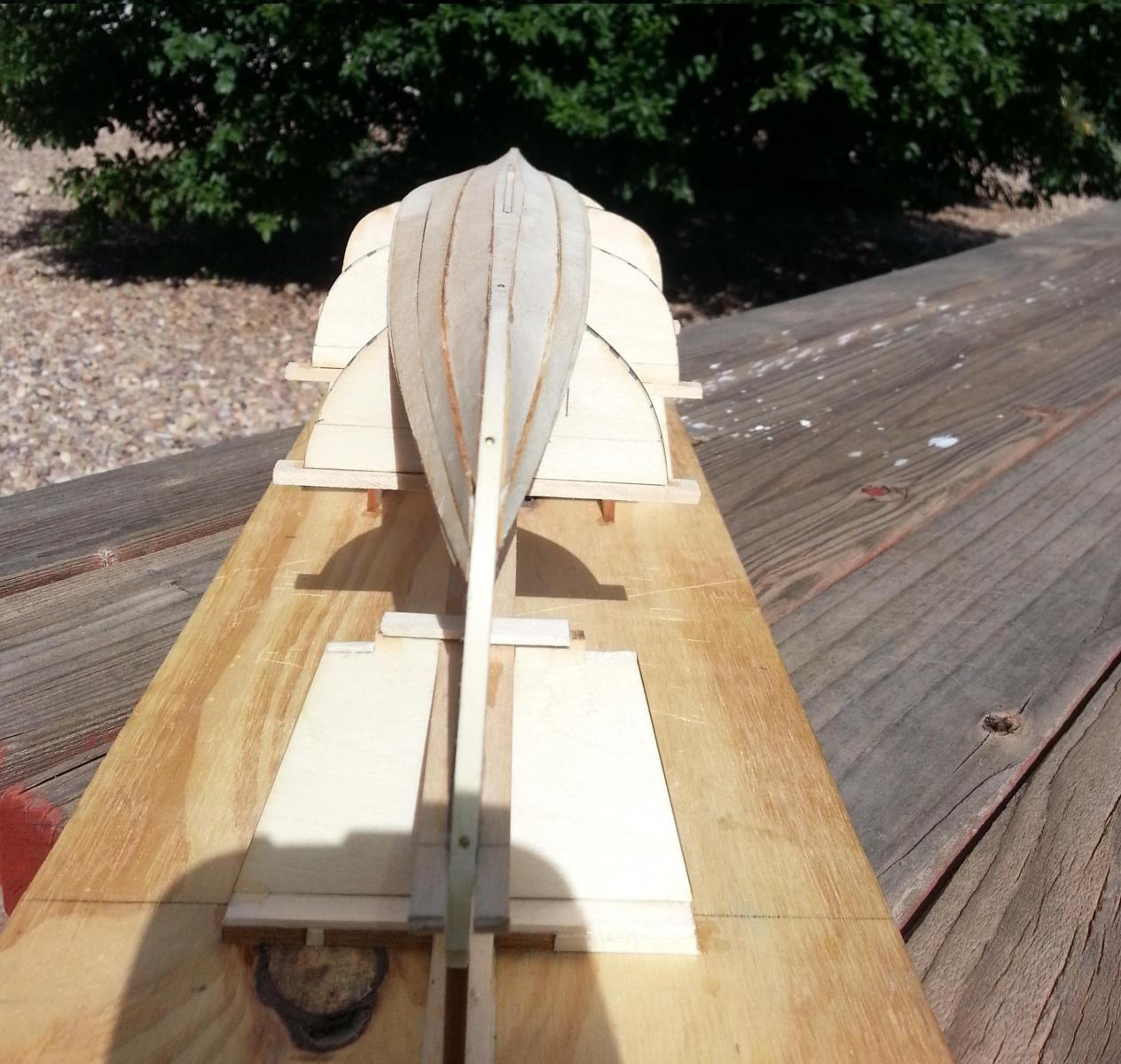
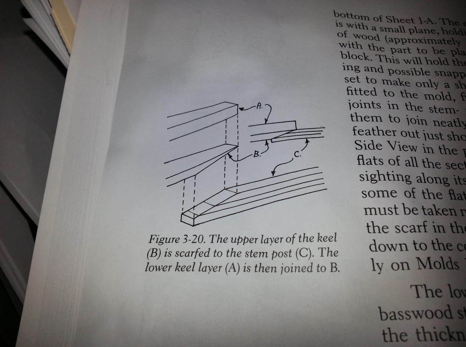
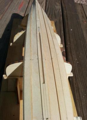
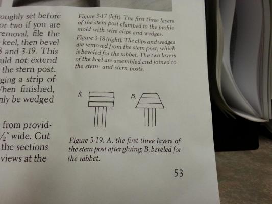
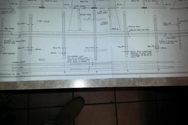
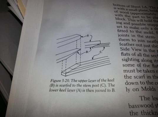
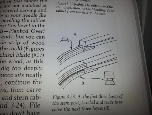
Greetings to all, Let’s start by saying that I have good news and bad news. The good news that I have made some progress on my whaleboat and the bad news is that I have lost some photos documenting each step. Now don’t be alarmed, I’ll try to narrate the steps I’ve taken and take photos of certain aspects of the plans to show you what I am talking about. Upon completing the form, it was time for me to tackle the bow and stern post along with the keel. Now the process is a lot easier than what you may read within the book, “To Build a Whaleboat”. The bow and stern post is pretty much a lamination of 1/32” x 1/8” strips of timber that are placed along the bow and stern areas of your form. The total amount of strips used for both posts are six strips. The process I found easiest for me was to use my wife’s fabric steamer on each individual strip. After steaming it for approximately 30 seconds, I placed it on the form and held it in place with rubber bands until it dried. Once dry, I went ahead and repeated the same process for the second and third strip (glued to the previous one once completely dry). After the third strip has dried, it was time to bevel the rabbet onto the posts as seen in the first photo below. Once I was satisfied with the bevel, it was now time to turn my attention to the keel which consists of an upper and lower layer. At this point I was only concentrating on the upper layer which is a 3/64” x ½” strip of timber. The keel is pretty straight forward to make, as the second photo below will show you, so I’ll not bore you too much in the matter. Now the fun stuff was ready to begin, adding the posts to the keel. While it seems like a simple step, it requires a bit of finesse and a little bit of measurement. In order to fit the upper layer of the keel to the posts, I had to scarf the posts and upper keel and ensure that I had a smooth and continuous flow from bow to stern as the third photo below will show. After making the preliminary union of posts to keel, it was time to beef it up via the lower keel and final three strips of each post. The lower keel layer is 5/64” x ½” and gets its measurements from the plans. Once I cut my lower layer, I added it onto the upper layer, and prepared for the remaining three strips which is a repeated system of my first three strips. Yes; steam, form, dry, and glue. Once the last three layers dried, I continued the bow’s rabbet along the keel until making it meet with the stern’s rabbet. I then removed the whole assembly from the form and lightly sanded the posts edges to get rid of the fact that they were laminated pieces. (NOTE: The only exception to the keel is that you will need to cut the centerboard slot on the lower layer and wait until after your model if framed as a means of maintaining the strength of the keel as a whole.) Until next time, Ray
-
Hello Carl, I was just going over the forums in order to see who else was building the NB Whaleboat and am glad I am not the only one. I started the post today and hope to view others tidbits of information I may incorporate into my build. I hope to see more progress soon. Ray
-
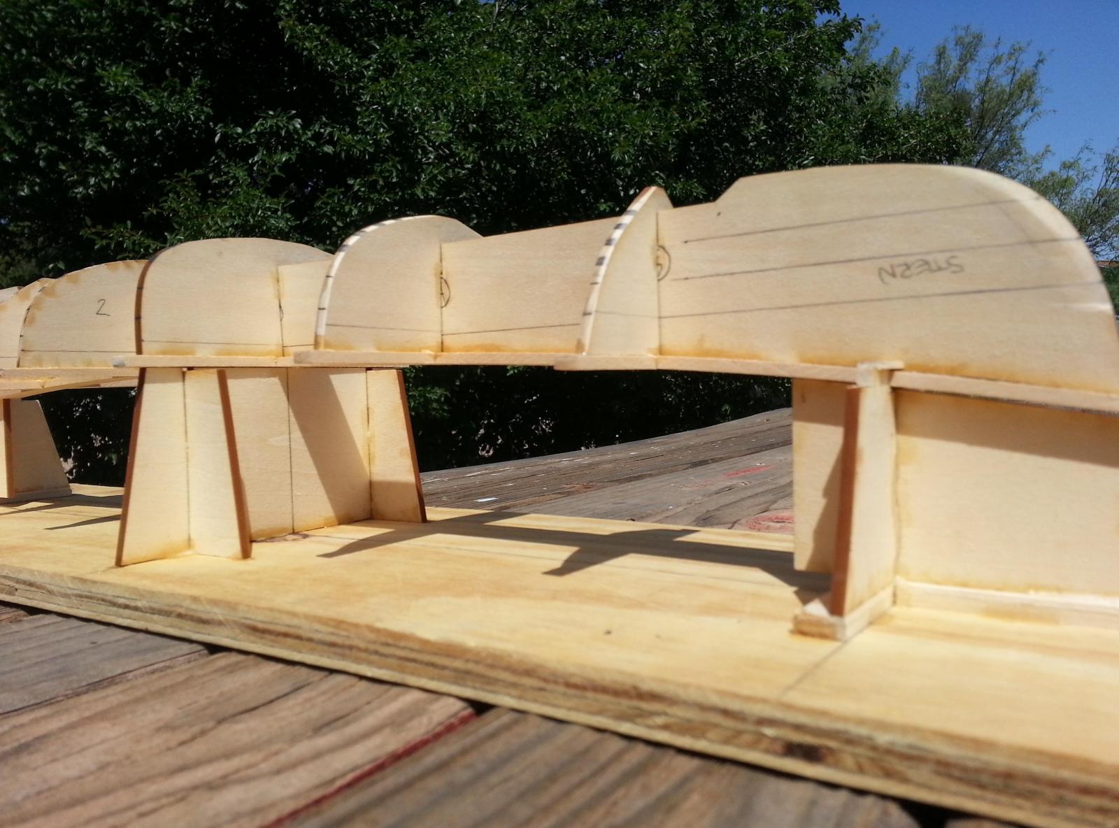
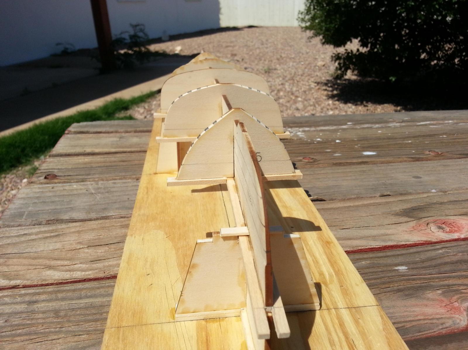
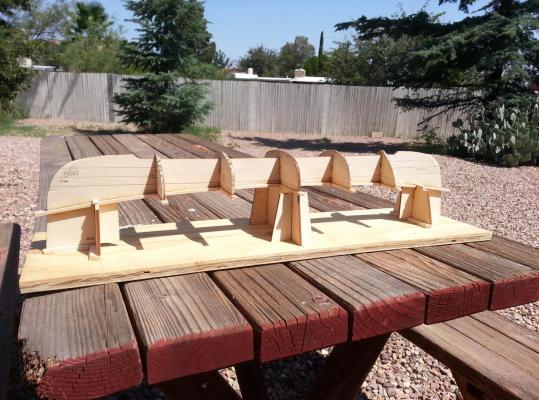
Greetings to all, Please excuse the fact that I have been away from the ship yards for a while. It’s been pretty busy over here with the move and having to fix a leak under the sink that I could not find until after I broke under the concrete slab. Well as most of you know, I had the New Bedford Whaleboat kit a friend of mine gave me for the assistance I provided him on the back porch of his house. For starters let me give you a brief history lesson of the New Bedford Whaleboat. “From 1720 to 1920, nearly 60,000 whaleboats were consumed by the American whaling industry. With a useful life of no more than three years, whaleboats were discarded on the spot throughout the costal U.S. and around the world. Remarkably, only a dozen or two have survived to become part of today’s museum collection. In 1916, the Dartmouth Historical Society commissioned the building of a half-sized model of the bark LAGODA. Local whaleboat builder Joshua Delano was retained to build seven half-sized model whaleboats needed for the project. Delano built these models according to the design of the full-sized boats he had built for the whaling industry for more than 40 years.” Now that I have brought you up to speed, let us begin into my journey of the New Bedford Whaleboat. Well the first thing one should do is inventory all supplies within the Model Shipway’s kit. I did so and realized that there were a few missing items that I was able to acquire at my local Hobby lobby. After that was done, I looked over the plans and read, “To Build A Whaleboat, Historical Notes And A Modelmaker’s Guide” by Erik A.R. Ronnberg, Jr. I must say that this item is invaluable to the person who wants to tackle the whaleboat. After reviewing and reading everything, I tackled the whaleboat’s form by assembling the profile and section molds. Before you begin gluing the section molds to the profile mold, it is best to make your bevel for the battens and planks to section molds 1, 2, 4, and 5. Once complete, mark the areas on the section molds were the battens will be placed and the water lines that will coincide with the profile’s waterlines. Keep in mind that these marked areas are just a rough guide that will assist your placement of the battens. Upon completion of the form, I tackled the horses that will have the form mounted upon. I must say that Model Shipways tries to do their best by these models but there are certain places that need to be tweaked just so for a proper fit of the form upon the horses. I made a construction board in order to glue down my workhorses. First you will have to establish the centerline down the length of the board and place the midship horse, widthwise for form section 3, as carefully as you can due to the fact that the bow and stern horses will take their measurements from this one. Upon the proper alignment of all 3 workhorses, I placed and glued my form on top and let it dry. The following three photos will show you what I have thus far. Until the next episode, here’s wishing you and yours a happy voyage home.


- 31 replies
-
- 6
-
-
- new bedford whaleboat
- model shipways
- (and 1 more)
-
Hello Gabe, I am glad that I've given you insight at the possiblilities these marvelous models can provide. I must confess that the Triton was my first scratch built POF model I've ever built. On Facebook I see a lot of people that go to the gym with the mentality of, "Go big or go home". That being said, I brought that same mentality to my build and have never regretted a moment of it. Dare to dream big. Here's to breaking the barriers set in place by your own imagination. Warm Regards, Ray P.S. Woody also says hi.
-
Hola Daniel, Sierra Vista is in Arizona and Mesa Verde is in Colorado. It can easily be driven to in about 9 1/2 hours. You may think that it's a long drive but the scenic view is amazing and the time goes by pretty quickly. Warm Regards, Ray
-
Hey Gabe, I was just checking in to see fellow Triton builder's progress and I take mt hat off to you Sir. Your level of dedication at this scale is truly amazing. I can't wait to see where you may go from here. Warm regards, Ray
-
Hola Mija, It has been a while since last I looked into your progress and I must admit that your work looks excellent. I am also glad that you are feeling better enough to work a little bit on your Red Dragon. The extra details you are adding is really thought out and I can tell that you are enjoying your journey. I look forward to more of your progress and remember to take it easy and rest when your body tells you to. Tu Amigo, Raymond
-
Grant, I really appretiate your kind words. I look forward to seeing your work. Ray
-
Hola Maestro, Your progress is looking amazing. A friend of mine has sent me frame drawings of the Essex and am planing to build a complete ship of her at 1:64. It is a little smaller than your Triton but I will use your log as a basis of building my Essex. Bueno mi amigo, I'll say good-bye for now. Ray
-
Uncle Si, Sorry for the delay. I had some left over wire used for an alarm system that seemed to be the right size for my ring bolts. Once the wire was stripped of its plastic sleeve, it came out to be 1/32" in diameter. I hope this helps. Ray
-
Thanks Bindy, I hope everything is well with the family. I have truly enjoyed my experience with, and quite proud of, my Triton (especially after that slight misunderstanding at the very beginning). I am now scheduled to work on the "New Bedford Whaleboat" that a friend gave me due to the assistance I gave him with the enclosure of a porch. I must confess one thing, I am still thinking of the Triton and I may/may not try a full build of her. Seeing that I will be stationed here for another three years I am seriously considering it. Fair winds to you and yours, Ray
-
Greetings Mick, I appreciate your words and I must say that you will enjoy your journey with the HMS Triton. I've always wanted to tackle a POF and with the Triton I was able to do just that. In regards to basswood I have had no issues. I believe that it cuts well, holds a pretty decent edge, and can easily be manipulated to what you ask of it. I will sit on the sidelines and watch you progress on this marvelous build. Cheers, Ray
-
Hello Mick, I am glad to see that you are willing to come aboard and take a crack at the HMS Triton. I too wanted to try my hands at a POF model and the Triton seemed to fill the criterias I was looking for. She will be a fun build and I look forward to seeing you progress along. Cheers, Ray
-
Hola Daniel, I do not see anything wrong with taking ideas from the Diana and trying to make "your Triton" look like her. I truly believe that as long as you are happy with your progress, then that is all that really matters. "Usted es el Capitan de su barco" you are the captain of your ship.
-
Yuri, It is beautiful. Do not worry about the progress. Little here, a little there and soon your ship will be complete.