
HOLIDAY DONATION DRIVE - SUPPORT MSW - DO YOUR PART TO KEEP THIS GREAT FORUM GOING! (Only 36 donations so far out of 49,000 members - C'mon guys!)
×

G. Delacroix
-
Posts
187 -
Joined
-
Last visited
Content Type
Profiles
Forums
Gallery
Events
Everything posted by G. Delacroix
-
 They are inside, they would be inaccessible to the outside.
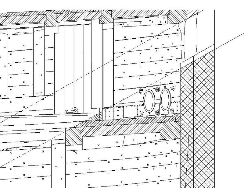
-
Hello, In the French navy , and whatever the ship (vessel or frigates), the hawse is closed by a hawse-plug which is a plug of poplar wood. There is two models: one that completely obstructs the hawse, it has a conical shape and it's used at sea. The other is almost similar but it is cut along its length leaving a channel to pass the cable anchor. It's use when the ship is anchored. These plugs are immobilized by four ring-bolds implanted around the hawse. GD
-
Very good job, congratulations. GD
-
Hello, You have to take a carriage used after 1758 ie the one on the drawing from above. The height of this carriage is surprising, it is necessary to verify its height so that the gun is in the middle of the port. The bottom drawing is taken from the monograph on the 64-gun ship Le Fleuron. This 1730 eight-pounder cannon has a pre-1758 carriage, which is here proportioned for a 24-pounder gun port. It is a special arrangement for the Fleuron. Its dimensions are not common. Gérard Delacroix
-
Hello, In the seventeenth and eighteenth centuries and probably before, in France, the cannons were all rigged in this way. The breeching passes through the gun carriage. The through holes are worked accordingly by rounding the edges. GD
-
Hello, Good job and excellent finishing of this barge framework. GD
-
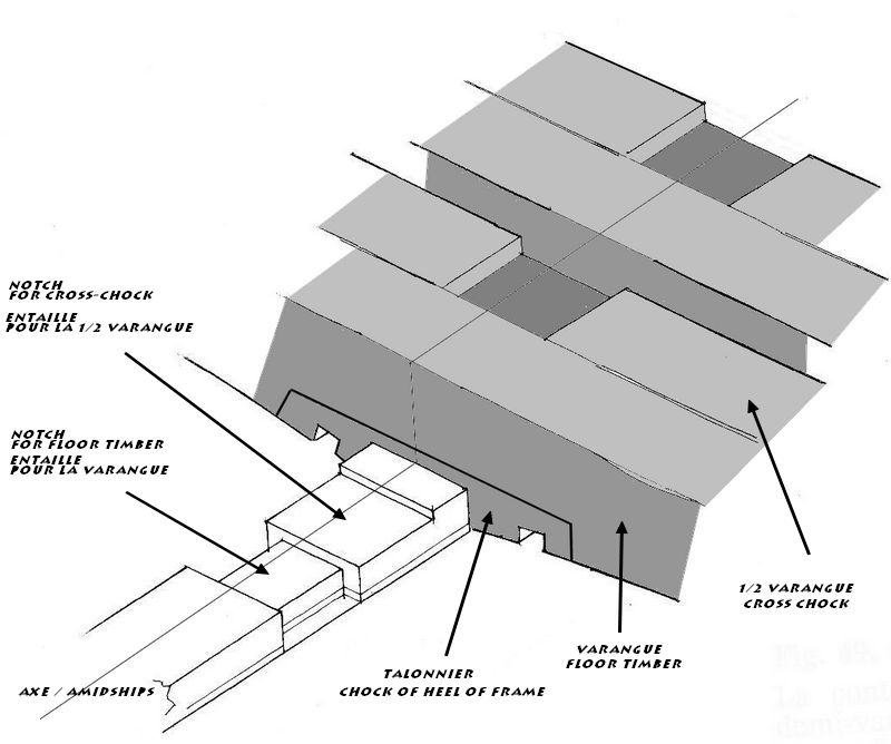
Hello, A "talonnier" (heel-piece ?) is a filler piece to avoid the use of large wood. It is a supplementary piece which has no fixed dimensions, it serves only to fill the middle of the floor timbers whose original part lacks wood. The one drawn by JB is not entirely accurate, it does not correspond to the time data. Here are, for example, those used on the 24 prd frigate L'Egyptienne:
-
Hello, Jean Boudriot reversed some pieces in the installation of the couples on the drawing published by GB. The correct configuration is as follows:
-
The length of the planking parts, whether for the hull or the decks, must be between 22 and 50 French feet or 7.15 to 16.25 m. depending on the location on the framework and the availability in the wooden parks of the arsenals GD
-
Hello, In French construction in the eighteenth century, the fitting of orderly end of plank was not practiced. And for two reasons: - it would be wasteful to cut a beautiful plank for a simple aesthetic reason - the longer the plank is, the better the deck strength is. As a result, the end of plank are positioned randomly, placed on the nearest beam but avoiding placing a joint with less than three or four plank on the same beam. GD
-
An arsenal is a place where we build and arm the warships. It's also in this place where the first models that represented the vessels under construction were realized. These models have given the term "arsenal model" The term is indeed equivalent to "admiraly models". GD
-
You have to rig your cannons as in this photo to the reserve of only one tackle in the back. The dimensions of the elements are as follows (guns of 6 / guns of 8), real dimensions to scale for your model - single and double block: 175mm/200 mm - rope of tackle: diameter: 17mm/20 mm - breeching: diameter : 32mm/47 mm GD
- 9 replies
-
- 13
-

-
Well let's try to be concise: Arsenal modeling is a discipline of naval modeling, the oldest and most demanding. This activity consists of replicating to scale down the design and construction of old ships. This reproduction must be as faithful as possible in the making of the parts which constitute the framework, the arrangements of the decks, the equipment and the decoration of the original ship. The construction of the masts, the rigging and the sails are not imperative, it is a question of personal preferences. In France this activity was practiced in the arsenals of the king since the XVIIth century, Jean Boudriot "awakened" this practice in the Seventies and the name has remained and is still used today. The different parts must be perfectly conform to the original parts, their assembly also. Bolts, nails and treenails should be reproduced as far as possible. If a keel has four parts, these four parts must be represented and assembled as true with scarph, bold et nails. No facility, modern materials or artifacts of manufacture are allowed in the traditional arsenal modeling unlike some models makers who make superb models but out of established conventions (absence of framework, sculpture in series (even metal), artillery in resin , etc.). For the enthusiasts who are often very cultured on the subject, these models are not part of the true model of arsenal. The arsenal models are based on monographs or personal studies which are the representation of the real ships, they are not plans of model. These books are the result of advanced knowledge of the naval architecture in general and the ship concerned in particular (era, builder, place of construction, peculiarities, etc.). It is often a long-term process that requires a great deal of research. Many regard it as a noble activity, close to art by the skill he asks. GD I do not know if the automatic translation will reflect the meaning of my talking...
-
Sure, JC Lemineur drew the frames of the V74 that were demanded by the modeling sphere, but was this necessary? Many 74 are built with their frames and many have an excellent level of job. The good question is: is it reasonable for a publisher to offer a book whose content is questionable? It was perhaps excusable it 20 years ago but today, knowledge in this discipline have evolved and model-makers are much more knowledgeable and especially more demanding. Certainly there are no monographs free of errors but they are often minor and undetectable in the reading of the plans and only discovered during the construction. GD
-
Well to name only two or three: - lack the drawing of the rising-wood (contrequille) on the frame, annoying for implantation - the thoard (collet) of the varangues is wide and flat as in the XVIIth century, period that JC Lemineur practices much more and which had probably influence him, - No cross-chock on filling transom, - etc. The author has probably had good reasons to practice like this but these details are quite disturbing for the modelmakers who are now familiar with the subject. GD
-
Hello, I worked with Jean Boudriot and I was his friend for many years and I can tell you that the 3D drawings of the V74 are not real drawings calculated on the drawing board, they are only photographs redrawn keeping only the desired part. On the other hand, it should be noted that the V74 is not representative of the French construction of the 1780s, the model preserved at Rochefort which was used by JB as a working basis, goes against many building rules of the time. But this does not detract from the exceptional contribution of information that are contained in the four volumes of the V74. For the "Fifth volume" it contains some strange details in the framework plates (11 plates), the rest (31 plates) are enlargements to 1/48 of the four volumes plans. A little expensive just for enlargements ... This is not a négative criticism, the V74 is an indisputable reference of the French shipbuilding of the end of the eighteenth century. Jean Boudriot composed an extraordinary document on the practices of this period, but we must go beyond his reading to appreciate all the subtleties and therefore the peculiarities. Jean Boudriot is at the origin of the revival of the "arsenal modelism" and only for that, we owe to him a lot. GD
-
Hello, The complement "Rigging and sails" is not published by Ancre but by its author to the address that you indicated. Blockplane, good job. GD
-
Hello, In the photograph showing a cannon moored along the wall (in fact my section of the Fleuron), we can observe the device that keeps the port-lid tightly closed. We can see the handspike (heaver ?) of the gun placed across the port, it serves as a restraint with two seizing passed through the rings which are inside the port-lid when it's closed. This is very rarely illustrated. GD
-
I agree with you that the whole of the decoration is generally symmetrical but we must be vigilant because some parts of the original drawing are not: they are those indicated with a red point on this extract of the plans.
- 728 replies
-
- 16
-
-
- le fleuron
- 64 gun
- (and 1 more)
-
Hello, On the monograph drawings, the decoration is not symmetrical as in the original drawings. Here is the realization of Jacques Maillière at 1/24. Regards, GD
- 728 replies
-
- 21
-
-
- le fleuron
- 64 gun
- (and 1 more)
-
Hello, The monograph of L'Amarante is not an Ancre production, it can be found here, in its author / publisher web site. GD
-
Hello, Mr Lemineur communicated the following: It may be well to point out that the Soleil Royal of Heller as well as that of Tanneron exhibited at the Musée de la Marine in Paris are not the Soleil Royal of 1668 built by Laurent Hubac in Brest. It is actually the 2e Soleil Royal, named on cale "Le Foudroyant" and renamed the Soleil Royal in 1693. This second Soleil Royal, built by Etienne Hubac, Laurent's son, measured 170 feet long while the length of that of 1668 was 164 ½ feet. It was pierced with 14 ports on the low battery. The 15th port, reserved for hunting, was not armed. The piercing of the Soleil Royal of 1668 was to 16 ports, the 16th of the front, destined for the shooting, was armed only at the moment, the 15th canon of the front being removed from its port to be put in battery to the so-called hunting port! The distribution of the artillery on the 2nd Soleil Royal which determines the general architecture of the vessel is therefore totally different from that of the Soleil Royal of 1668. Finally, in order to demonstrate the extent of the gap separating Heller's model from historical reality, it is necessary, for example, to compare the draught of water. That of Heller measures 4 cm on the 1/100 scale and therefore 4 meters at scale 1/1. On the Soleil Royal of 1668, it was 23 ½ feet, that is to say 7 meters and 23 cm, the French foot of King measuring 32,48 cm. There is therefore a difference of 3.23 meters and therefore a total lack of conformity and proportions. Unfortunately, for people too credulous, the model of Heller demonstrates a total lack of intellectual honesty against which we struggle most of the time without success. GD Approximately Translate by Google
- 2,696 replies
-
- 5
-
-
- heller
- soleil royal
- (and 9 more)
-
What are these? does anybody knows? thanks.....
G. Delacroix replied to BIGMAC's topic in Masting, rigging and sails
Hello, I must say that I have never met the name of the accessory that is quite common in Latin rigging. Present at the end of the yards but also on the head of the bow for the same purpose: to save sails. This element could it be a wooden disc as it would appear on some drawings? Why not but I doubt because the weight of such a disk would bend the yard. Concerning the curvature of the yard, it's natural and due to the weight and the flexibility of the yard wood (pine). For huge galleys yards I studied, the "comite" or executive chief of the galley (that is, among others the function, sail master), takes the curvature into account when cutting the sails. The arc of this curve is, at rest, between 3 and 4% of the length of the yard so about 3 feet to a yard of around 100 feet for the longest of them. With the wind, the rope retaining and swelling of the sail this curvature increases. Regards, Gérard Delacroix -
What are these? does anybody knows? thanks.....
G. Delacroix replied to BIGMAC's topic in Masting, rigging and sails
Hello, Plans are probably pretty easy to find: the square-rigged ships were inspired by The Santa Maria of Columbus, Latin rigged ships come from the Nina and the Pinta. GD -
What are these? does anybody knows? thanks.....
G. Delacroix replied to BIGMAC's topic in Masting, rigging and sails
Hello, This "object", which is composed of a large piece of sheepskin with its all its wool, is designed to avoid tearing of the back sail by the top end of the fore yard when they are handling. This yard end is very flexible. The great latin sails are succeptibles to many positions to function properly, this involves yard movements sometimes poorly controlled with high winds. The bottom of the yard is often equipped with this accessory but this part is more controllable because it is steeper and it is headed by a rope. Regards, Gérard Delacroix- 30 replies
-
- 11
-