


AON
-
Posts
2,875 -
Joined
-
Last visited
Content Type
Profiles
Forums
Gallery
Events
Everything posted by AON
-
 Trim cutter just got delivered. I hope to get some upper deck beams cut tomorrow so I can fit the bowsprit mast step and move on.
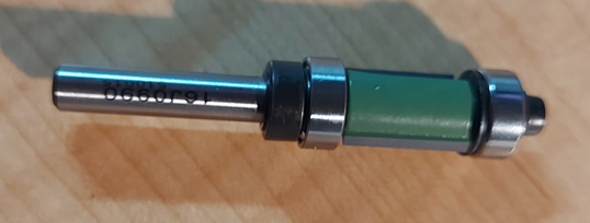
-
Been there. Still doing that.
-
It has been just over three weeks since my last post and I have been doing quite a bit over this time. I lost half a week due to another eye injection. This is reoccurring, every twelve weeks now. I spent a few days making a sounding board for the Library board Chairperson. They have a mallet that they rapped on the table top, they shouldn't do that, bad for the table. What I made is an oak puck shaped disk, sanded, stained and polished with beeswax. I also epoxy glued a non-skid pad to the underside so it doesn't slide off the table. The dot on top centre is a 3/8" dowel insert... like a target to aim for! I made a deck beam rounding jig (like what Mark - aka SJSoane described in his build of the Bellona) for my upper deck beams. I prepared stock for all twenty-eight beams and purchased a router trim bit from Lee Valley Tools with both an upper and lower guide roller bearing. I've had bearings fly apart and the thought of that happening and ruining my jig is not something I relish. The additional bearing will hopefully be my protection from this ever happening. I am presently awaiting delivery... I ordered two spare rollers. I also ditched the trail board carving and prepared more suitable Castello blanks for the carving. These are ready to go (glued and cured to a base board and put in the clamp). I completed the upper cheek installation (you see this when I install the trail board carvings) and am into the forward gundeck beam assembly and bowsprit step. Lots going on.


-
I find making card stock templates of items that need to nest against others a tremendous help. I also believe the hatch frame covers had lanyards attached so they wouldn't get washed overboard. If this is true you could make the cover and show it removed perched up on one corner of the frame. Maybe someone could confirm the lanyard as I cannot seem to find the source of this information. Great work BTW!
-
Good morning Mark. I want to thank you for your posting #1967 (7 Nov 2020) explaining how you made and use your deck beam jig. I am about to start re-making some upper deck beams that have a noticeable rise but my freehand method was a terrible idea (they've been torn out)... then I recalled you made a jig. It took a bit to find until I decided to do a search with "deck beam jig" and *BAM* there it was. I suspect my curved deck beams will be much better on the next run. Alan
-
Daniel I found "guns" to be quite confusing. Discovering that swivel guns on the fighting tops and carronades on the weather decks weren't counted as guns.... in this age I can only wonder why? Even some of that era questioned it. Alan
-
HMS ANSON 1781 by albert - 1/48 - 64 guns
AON replied to albert's topic in - Build logs for subjects built 1751 - 1800
DITTO! 😉 -
Dowmer I believe you might be correct. Carvers use boxwood, particularly Linden in this area, for normal figures at 10X or more the scale I am presently attempting. Alan
-
Jared... something to think about but as you know David Antscherl is a member of the club and is much better at it then I might ever be! Druxey... I had a brain fart and typed boxwood instead of basswood. I've corrected the post. Thanks for catching that. My chisels are quite sharp. It was likely a flaw in the wood. I suspect I will add the foot to the piece separately. If I do it well no one should notice.
-
Hope everyone had a Merry Christmas and Happy New Year! some update pics The Taffrail has been drilled and pinned to the stern, and the counter timbers have been cut back to a proper termination level. The Griffon/Gryphon carvings are coming along but at such a small scale I wonder if I just need more practice or should I use a different wood — Castello versus boxwood basswood (Linden), as I've already lost a hind foot! I tried using rotary cutters but reverted to mini chisels. We'll have to wait and see how the head turns out! 🤔
-
Or the seal to the prop shaft is dry and tight?
- 72 replies
-
- 1
-

-
- Miss Adventure
- Model Shipways
- (and 2 more)
-
Golden Hind by Rock_From_Korea - 1:48
AON replied to Rock_From_Korea's topic in - Build logs for subjects built 1501 - 1750
They look pretty darn good to me! -
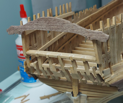
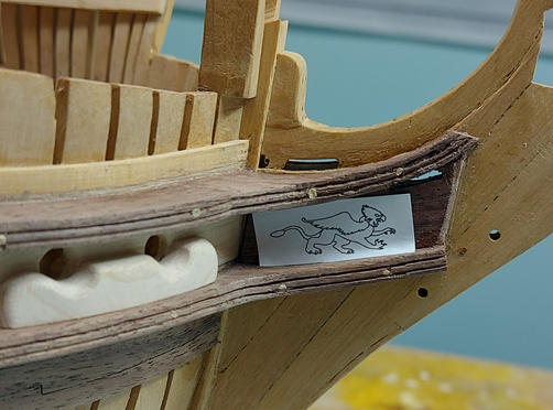
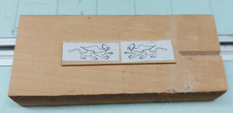
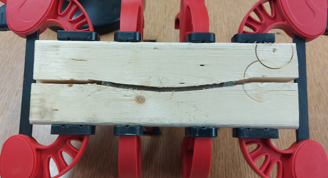
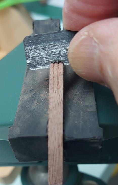
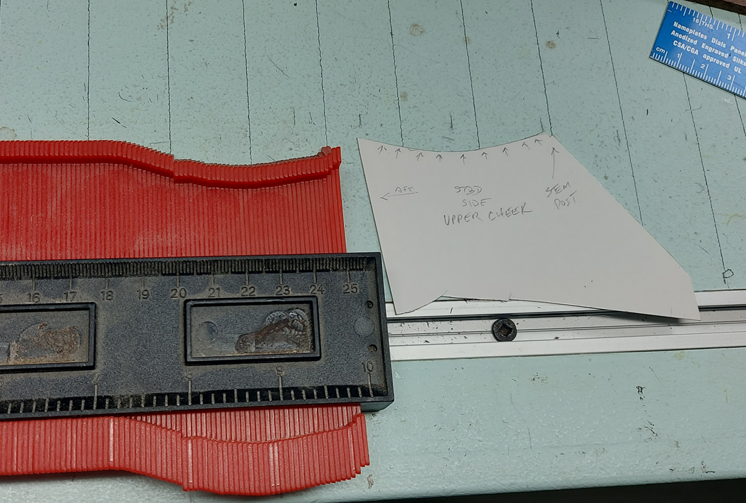
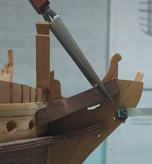
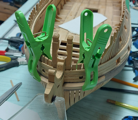
Well, I managed one of the two upper cheek finishing bits. It is presently soaking to be removed from the baseboard. I also installed the trail boards and decided on the figure, a griffon or gryphon if you prefer. The drawing has been mounted to some bass wood (linden) and that glued to a baseboard in readiness for carving. As I am getting tired of looking at my mistake at the stern, I've cut out the transom taffrail board in black walnut, steamed it, and it is presently clamped and drying. The clamp piece is a scrap 2x4 piece of lumber cut to the curve of the present stern taken with my profile gauge. I will not unclamp it until after Christmas. I intend to remove the offending counter timber tops sometime soon (in the new year) and will replace them with the taffrail board.
-
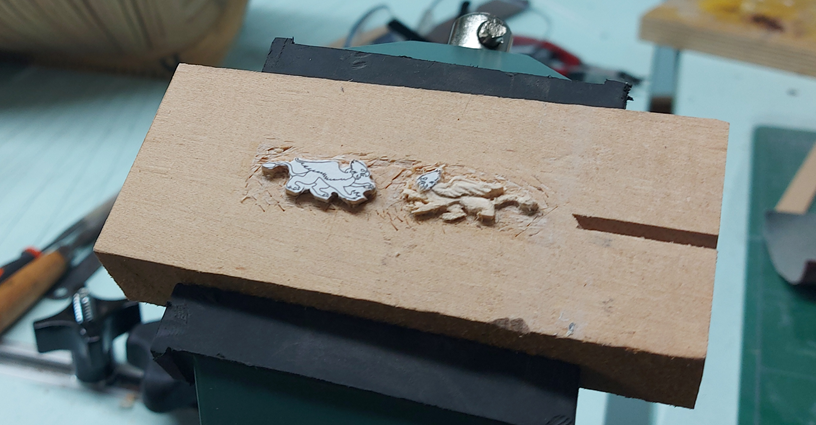
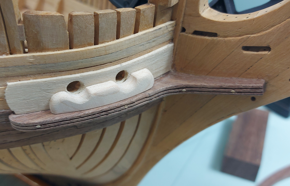
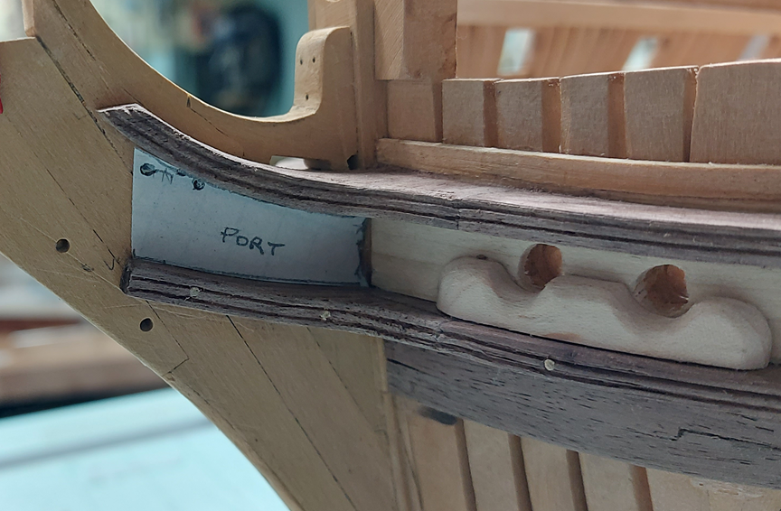
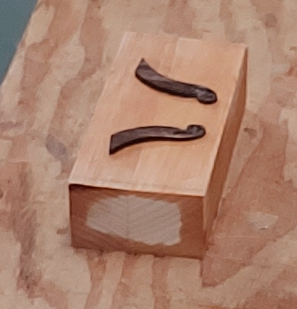
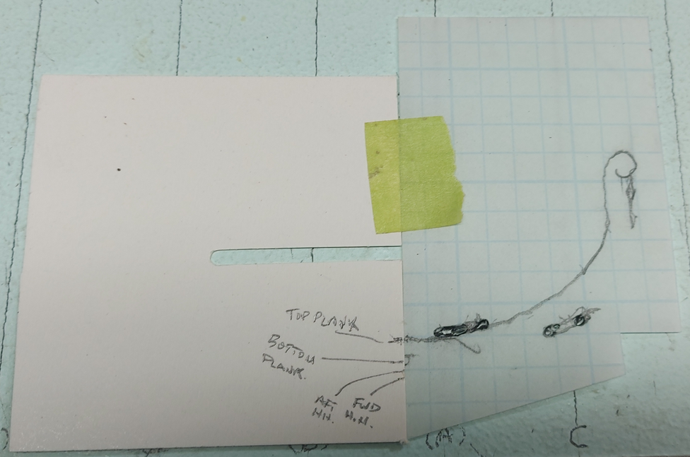
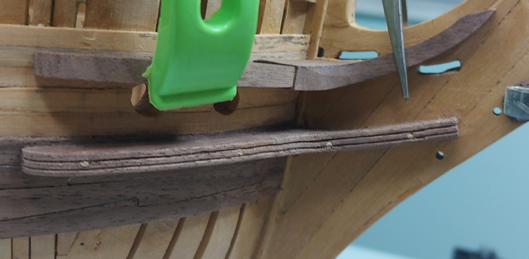
Having established the gap between the upper and lower cheeks, I made the hawse bollard and backing plate. I decided the clean white look of maple was a nice contrast. The backing plate was steamed and clamped. I couldn't get back to it for three days... it was quite dry and had no spring back! I completed shaping the upper cheek pieces, scraped the grooves into them, then glued them into place. They just need to be drilled and pinned similarly to what I had done to the lower cheeks. The paper template in the top photo is for my trail board. The contract reads as follows: To have a double trail board, and a lion or figure, as shall be directed. Handsomely carved; the rails and supporters handsomely wrought with mouldings. I searched the internet for lion figures and found a few that might be suitable, but then thought the Chimera monster (that Bellerophon killed) which is mostly lion… or a Griffon (as seen on the crest of the last stone frigate) which is partly lion might be more interesting, but also these might be more difficult to carve, especially to fit a ½” tall x 1” long space. Decisions! I also have had two attempts at the third piece of the upper cheek that rises up the main bracket behind the figurehead. These have both been tossed in the scrap bin. Third time is the charm! These two above had been soaked in 90% Isopropyl Alcohol (cotton batten soaked, laid over the figures and wrapped in clear cling wrap aka Saran wrap) over night to allow me to peel them off the block of wood. They were glued on with drops of yellow wood glue. The block is clamped in a vise to allow me to carve away at them. Not sure how much I'll get done before Christmas.
-
I had been working on the lower cheeks and have since started the upper cheeks. I began by making a card template of the hull using my profile gauge. Then I traced the stem works to fit the upper cheek between the gammoning slots. The lower cheek was made in two pieces, glued and pinned with wooden dowels requiring #57 drill bit holes. The upper cheek will be in three pieces of which I have two pieces roughed. The piece against the stem works is longer than needed. I will make the mating piece longer and trim the two to fit. Tomorrow I will make up the hawse bolster and backing plate pieces to help with spacing and alignment of the upper cheek pieces.
-
forgot to mention is was very cold this morning up here.
-
They can easily be cleaned up with a very narrow chisel, if you have one. If not, possibly I can bring you one 😃
-
Over take you? I hope not. Your build is one of the two I refer to religiously!
-
My first attempt at the lower cheeks was not a complete disappointment. Both lower cheeks were aligned with each other and a nice gentle slope on the forward arm. Made in two pieces... the joint wasn't quite good enough, even for me. 😁 My second attempt should be the keeper. Presently busy making one Christmas and one birthday present in the shop, on the sly, in between work on the cheeks. December is a busy month.
-
I think you need to sand those spots, finishing with very fine grade sandpaper (320 grit), and after a through cleaning, re-apply the shellac in those areas.
-
Golden Hind by Rock_From_Korea - 1:48
AON replied to Rock_From_Korea's topic in - Build logs for subjects built 1501 - 1750
The small details make all the difference. They both look wonderful! -
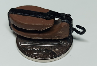
With a couple figures done and the three rows of 4" planking completed, it is time for a change before I go back to yet more planking. I decided to complete the assembly of my 3D printed viol/vyol block. The strapping is blackened card stock. The hook is copper wire that has been twisted and filed to shape. The completed block is placed on a 5cent piece for scale. I then started on the outer lower halves of the lower cheeks. Used some scrap pieces (of which I have plenty) for this first attempt. They fit up quite nicely. Still require shaping and rounding the edges. I'll need to make myself a scraper. Now to attempt the forward halves of the lower cheek assembly.

-
Not sure what I am supposed to see. I did sleep in so maybe I'll need a moment. A moment later.. I see it, the ring on the too of the lower capstan. Looking good!
