madtatt Posted May 17, 2025 Author #91 Posted May 17, 2025 Today, it was all about properly securing the masts to the deck. I’m always a little nervous before such important steps. That’s why preparation is key to ensuring everything goes smoothly. That’s how I did this small plate that serves as a support for the stop angle. By placing it on the bridge house, I can quickly check the angle of each side of the mast. This is important because the time window is very small. I use superglue with a long setting time, but it still has to be done quickly. I won’t keep you in suspense, but it worked. I laid some more rope next to it and had a sailor check the ropes. And everything went smoothly at the rear as well. Phew… The deck amidships is slowly filling up. Now I can continue working on the bridge houses. ccoyle, goetzi73, Canute and 6 others 8 1 Greetings from Germany, Joelle. Follow me on Instagram
madtatt Posted May 18, 2025 Author #92 Posted May 18, 2025 (edited) Good morning everyone. Another question for Jeff. You left out the small handwheel on the square mushroom structures and changed the height. I also think it's a ventilation duct and not a hatch. You took the height of the ventilation duct from the picture of the museum ship. However, there it's also positioned a bit further forward. And now to my thoughts. I found an original photo where the bridge houses are clearly visible and brightened it up a bit. However, I can't see these structures at all in the photos. Whereas the wheelhouse is quite clearly visible. Could it be that the height of the ventilation ducts on the museum ship was only subsequently changed? Otherwise they must be visible from the front view of the bridge house, like here, again on the museum ship. And another question that occurs to me, Jeff. Where did you get the information that these cable drums were installed on the bridge houses? I've carefully reviewed all my photos of the original ship, but I can't find her on any of them. 🤔 Edited May 18, 2025 by madtatt ccoyle, yvesvidal, GrandpaPhil and 2 others 5 Greetings from Germany, Joelle. Follow me on Instagram
madtatt Posted May 19, 2025 Author #93 Posted May 19, 2025 (edited) Hi Jeff, it's me again. I discovered something else interesting about the pretty good and well-known picture of the Mikasa at the Vickers shipyard shortly before its completion. I enlarged the bridgehouse and discovered the gratings of the accommodation ladder. See green arrows. Since I want to show the ship at full speed, I need them stowed. What I can't find, however, are the drainpipes you added. Is it possible that these were also added to the museum ship later? To prevent tourists from slipping when its rain? 😁 Edited May 20, 2025 by madtatt Canute, Herby63, king derelict and 1 other 4 Greetings from Germany, Joelle. Follow me on Instagram
madtatt Posted May 24, 2025 Author #94 Posted May 24, 2025 (edited) Now that the lower part of the masts is firmly anchored to the deck, I can turn my attention back to the bridgehouses. First, I soldered more attachment points for the rigging. It simply holds best. As mentioned in the previous post, I noticed two dark squares. I believe these can only be the gratings of the accommodation ladder. Since I'll be showing my ship at full speed, as usual, they'll have to be stowed there as well on this model. But that won't happen until after I've attached the bridgehouses to the deck. What I'm already doing is attaching the corresponding davits. I've identified them in the following pictures. Rear bridgehouse.... And the implementation by me. And at the front. Strangely, my image editing program didn’t allow a green arrow. So a white arrow points to the davit. Note that the davits point to the right and left. Great, I love searching for details like Sherlock and then adding them. 🔎 Edited May 24, 2025 by madtatt Typo Herby63, GrandpaPhil, yvesvidal and 3 others 6 Greetings from Germany, Joelle. Follow me on Instagram
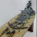
madtatt Posted May 25, 2025 Author #95 Posted May 25, 2025 Another little mini-update to round off the weekend. The only thing missing were the support poles for the awning, and then the base coat could be applied. The protruding details such as profiles, davits and the like are accentuated again with a light grey. In combination with the preshading, this creates a fine first contrast Now I can start aging next week. Javlin, ccoyle, egkb and 4 others 7 Greetings from Germany, Joelle. Follow me on Instagram
Jeff59 Posted May 28, 2025 #96 Posted May 28, 2025 Hi Jolle, been a little while since l last looked at this, busy working on my shed come workshop, l did say summer weather slows up modelling a tad, mines has stopped for weeks now 😂 you’re models looking brilliant, no surprises there 🤛 that last photo you put up of Mikasas Bridge is the after Bridge, you can tell by the position of mast into the deck on Bridge structure, this also shows that the ventilation trunking was here as well, definitely closer to the edge. l didn’t move this cause the etch deck was already notched out to suit kit. There’s also a round ventilation duct just behind this ? But lm afraid it’s extremely difficult to define at what period this is relevant to, it’s just a minefield trying to decide on the right direction 👀 The cable drums on Bridge structure beside the doors just picked from some coloured cad drawings of ship in her early days found on Museum website when browsing, shall see if l can find them and post them 🤛 oh and watch out for Bridge wing clashing against the after mast, think l ended up notching a little bit out of mast to get it sitting vertical. It’s only when building this model you realise how hard it is to do without solid evidence, very difficult trying to do the early 1902 version, photos at Vickers the only source, even the Bridge wing is slightly different when you look at the supports at the edge of Bridge wing. Have to say your doing a great job with d difficult task. Shall get back to you on those images, away back to my shed just now. 🤛 madtatt and Canute 1 1
Jeff59 Posted May 29, 2025 #97 Posted May 29, 2025 Had a Quick Look at lots of images on Mikasa Meuseum web site Jolle, you can spend many hours browsing , l know l did , always scanning the images looking for details. The drain pipes you mentioned, have found some older photos of ship that show them there, and one showing Bridge spaced in middle of Bridge wing 👍as l have said before a dedicated book on Mikasa is sorely needed. madtatt, GrandpaPhil, Canute and 2 others 4 1
Jeff59 Posted May 29, 2025 #98 Posted May 29, 2025 (edited) Hope this is off help to you Jolle, on that Bridge wing on after supper structure it’s the back of the Bridge wing and etch that clashed with my model, maybe it was just a mistake on my part, but worth checking. That photo you showed of Mikasa at Vickers might be the same one l used to correct the bracing on the flag staff, it’s definitely not symmetrical, you’ll see what l mean. Glad to help 🤛 Edited July 17, 2025 by Jeff59 madtatt and Canute 1 1
madtatt Posted May 29, 2025 Author #99 Posted May 29, 2025 Hello Jeff. Yes, the information about this ship is truly sparse and often contradictory. So, thank you very much for the wealth of information you've given me. 👍 I'll proceed as follows. I won't be doing the cable reel and drainpipes, as I can't see them in the photos that show them painted gray. So I'm going to finish the bridge houses now, just like you saw them in my picture above. I'm excited to see how it goes. Canute and GrandpaPhil 2 Greetings from Germany, Joelle. Follow me on Instagram
madtatt Posted June 9, 2025 Author #100 Posted June 9, 2025 After a short break, I’m continuing. The lower bridge houses are finished weathering and can be put on the deck for a test run. Now I have to think about the most logical way to proceed. I think the rear bridge house is not glued to the deck yet. Because directly behind it the steam pinasses come onto their cradles. It’s probably better to have a little more room for my fat fingers. For the armored control center, I lined the entrance with a profile. It was clearly too thin. And there isn’t much space in front of the bridge houses up to the tower. So I’ve already fitted the lower parts of the tower into their barbettes and made them move freely. They were practically impossible to move. And I’ve also prepared the lower ladders that belong on the mast. Herby63, yvesvidal, Canute and 4 others 7 Greetings from Germany, Joelle. Follow me on Instagram
madtatt Posted June 14, 2025 Author #101 Posted June 14, 2025 Just another small update that I had to do before moving further toward the bow. I was still missing the bollards and other small items that would go directly in front of the bridge houses. These are now also attached to the deck. This had to be done so that I could install the companionways that lead to the main deck. This means the inner area is almost complete. And so the bridgehouse was glued in front of the steam pinnaces towards the stern. Otherwise, it would have been difficult to install the companionways behind the pinnaces. Now I can start with the anchor area at the bow and have cut everything I need out of the boards. Herby63, king derelict, GrandpaPhil and 4 others 6 1 Greetings from Germany, Joelle. Follow me on Instagram
madtatt Posted June 22, 2025 Author #102 Posted June 22, 2025 Today we’ll continue without much ado. I had time over the long weekend to finish the anchor section. That was fiddly.😵💫 In this area, the Pontos set was used exclusively. KA failed to score points here. Of course, double-link chains had to be purchased again. It’s disappointing that two very expensive aftermarket kits like KA and Pontos don’t consider it necessary to include proper chains. 👎 Herby63, egkb, Jeff59 and 5 others 8 Greetings from Germany, Joelle. Follow me on Instagram
Jeff59 Posted June 24, 2025 #103 Posted June 24, 2025 See that you came to the same conclusion as myself as how to run the spare anchor chain as there was no information to go on here , l just stared at it for ages before thinking this set up made sense 👍 on the kit supplied anchor chains totally agree, didn’t know you could purchase these chains. Cracking job Jolle 🤛 haven’t been on site for a few weeks, busy finishing of my work shed that l started before retirement since summer weather permits this, looking forward to getting back to my own build soon though. You are right, the forward area at this point on Mikasa is crammed with details, but enjoyable. madtatt, king derelict and Canute 2 1
madtatt Posted June 26, 2025 Author #104 Posted June 26, 2025 I completely agree with you, Jeff. This model is turning out to be a mysterious adventure. But with a high level of entertainment value. Yes, the anchor chains really look great. If you need them, I'd be happy to send you the link to where I got them. I also installed them on my Bismarck. And I hope you'll be finished with your work shed soon and we can marvel at your latest construction again. 💪 GrandpaPhil, ccoyle, king derelict and 2 others 5 Greetings from Germany, Joelle. Follow me on Instagram
madtatt Posted June 29, 2025 Author #105 Posted June 29, 2025 Let’s continue unspectacularly. We’re still missing skylights, handwheels, and a winch on the main deck at the stern. First, another small collection in my printed organizer. Nothing complicated, so straight to the result. The deck continues to fill, both front and back. The small stuff on deck is now roughly completed. I would like to show you this wonderfully detailed skylight a la Pontos again in a close-up. That’s what sets these kits apart. Molded plastic can’t replicate that. Jeff59, king derelict, Canute and 5 others 6 2 Greetings from Germany, Joelle. Follow me on Instagram
madtatt Posted July 5, 2025 Author #106 Posted July 5, 2025 And immediately, I have the next nerve-wracking construction phase ahead of me. But I was particularly looking forward to this part. I’m starting to incorporate a miniature marvel of 3D printing technology into my model. The 50-foot steam pinnace. https://forums.kitmaker.net/images/emoji/google/star_struck.png?v=14 But first, I have to get it into the cradles and onto the struts. I made a jig for that. One each for the starboard and port sides. The stripes aren’t exactly evenly spaced on the two sides, and I have to take that into account. I now glue the cradles onto the gauge and can then align and change them easily without damaging the now quite delicate Mikasa. For example, the distance to the access to the higher deck is important, as the pinnace’s rudder extends quite far out. And toward the bow, I have to pay attention to the funnel rigging. I have the same problem with the cradles as I did with the cutter amidships. They don’t fit where they were originally printed. And besides, only three were planned. But the pinnace rests on four struts, so I need one more cradle. It’s nice that four boats will be hanging from the davits at the stern later, so I can repurpose the cradles. Then I took out the profiles and adjusted them. It’s better. And so the first pinnace could be placed in its cradles and placed on the deck for testing. You can see a faulty print in the hull. This has already been claimed, and I’m getting a new one. In front of the boat, you can see a thin round rod. This is supposed to simulate the funnel rigging. You really have to think of everything. At least you should try to, so you don’t end up on your backside in the next step. https://forums.kitmaker.net/images/emoji/google/worried.png?v=14 Canute, egkb, ccoyle and 6 others 9 Greetings from Germany, Joelle. Follow me on Instagram
Landlubber Mike Posted July 5, 2025 #107 Posted July 5, 2025 Beautiful work Jolle! The new 3D printed accessories for model ship kits is another advancement beyond PE. It's amazing that you can buy 3D printed bridges for a number of models - not sure how I feel about that, as that seems to be more about assembling than modeling. I have bought a number of 3D sets for my various kits to model small details like small boats, guns, ammo boxes, etc. Canute, madtatt, Jeff59 and 1 other 4 Current Wooden builds: Amati/Victory Pegasus MS Charles W. Morgan Euromodel La Renommèe Plastic builds: Hs129B-2 1/48 SB2U-1 Vindicator 1/48 Five Star Yaeyama 1/700 Pit Road Asashio and Akashi 1/700 diorama Walrus 1/48 and Albatross 1/700 Special Hobby Buffalo 1/32 IJN Notoro 1/700 Akitsu Maru 1/700 Akitsushima 1/700 Crane Ship Seishu Maru 1/700 Completed builds : Caldercraft Brig Badger CLC Annapolis Wherry Amati Hannah - Ship in Bottle Pit Road Hatsuzakura 1/700 Hasegawa Shimakaze 1:350 F4B-4 and P-6E 1/72 Accurate Miniatures F3F-1/F3F-2 1/48 Tamiya F4F-4 Wildcat built as FM-1 1/48 Special Hobby Buffalo 1/48 Eduard Sikorsky JRS-1 1/72 Citroen 2CV 1/24 - Airfix and Tamiya Entex Morgan 3-wheeler 1/16 Terminated build: HMS Lyme (based on Corel Unicorn)
madtatt Posted July 6, 2025 Author #108 Posted July 6, 2025 Thanks, Mike. I absolutely agree with you. Especially when it comes to all the little things. With cannons, small boats, and the crew for example. It's fantastic how much more depth these details can add to the model. The pinnace wouldn't get as much out of it, even with the set of pontos from the original kit model. But when I think of fully printed sections like the bridge you mentioned, I'm just as torn as you are. Where does model building end, and when do we enter the realm of simply assembling Lego bricks? But everyone has to decide that for themselves. I think, as is often the case, the happy medium is the right way. goetzi73, GrandpaPhil, Herby63 and 4 others 7 Greetings from Germany, Joelle. Follow me on Instagram
Jeff59 Posted July 6, 2025 #109 Posted July 6, 2025 7 hours ago, madtatt said: Thanks, Mike. I absolutely agree with you. Especially when it comes to all the little things. With cannons, small boats, and the crew for example. It's fantastic how much more depth these details can add to the model. The pinnace wouldn't get as much out of it, even with the set of pontos from the original kit model. But when I think of fully printed sections like the bridge you mentioned, I'm just as torn as you are. Where does model building end, and when do we enter the realm of simply assembling Lego bricks? But everyone has to decide that for themselves. I think, as is often the case, the happy medium is the right way. Canute 1
Jeff59 Posted July 6, 2025 #110 Posted July 6, 2025 Also agree, happy medium gives the best off both worlds. Watch when you position the boats on this deck Jolle, space is a premium, considering the Micromaster Pinnace is quite a bit shorter than the kit one, l found it a tight squeeze to shoehorn them in, that’s when l had to add extra steelwork supports to support the extra boat cradles, it just goes on forever Jolle 😂, you might want to check out the pinnacle style, l did remove the helm screen on the last one that l made to make it look like it was from another ship, did manage to gently break this of and change the rear cabin, this probably makes it a bit nearer the period for 1905. Shall put up a photo off book l purchased that was a good help for photos and info. Shall also get said info from you on anchor chairs for Bismarck definitely 🤛 Your model is coming on a treat 👍 madtatt, GrandpaPhil, Herby63 and 1 other 4
madtatt Posted July 7, 2025 Author #111 Posted July 7, 2025 (edited) Ahoy, Jeff. Oh yes, I've also noticed that space is at a premium on the ship. I don't see any end in sight. But the fun is also the challenge, right?! Thanks again for the helpful tips. I've also been thinking about the final appearance of the pinnaces. I examined the following two photos, although I don't know if they are the Mikasa's boats. The fact is that there was no helmet screen, just like there was no cabin. There was apparently only one tarpaulin. I'm a little torn about how to proceed. I'm really afraid of destroying the pinnaces when removing the two parts. As you know, they weren't exactly cheap and come from the other side of the world. I really have to think carefully about whether to take that risk or just install the boats as they are. There's virtually no historical evidence of this ship, including the appearance of the pinnaces. 🤫 Edited July 7, 2025 by madtatt Jeff59, ccoyle, egkb and 2 others 5 Greetings from Germany, Joelle. Follow me on Instagram
Jeff59 Posted July 16, 2025 #112 Posted July 16, 2025 Shall put some of my build log photos up to see if it helps 👍 Canute, Haliburton, Herby63 and 5 others 5 3
Jeff59 Posted July 16, 2025 #113 Posted July 16, 2025 Since you are working on these areas just now picked some random photos out, hope this gives ideas 🤛 Canute and madtatt 1 1
Jeff59 Posted July 16, 2025 #114 Posted July 16, 2025 Just taking these few photos to show you were l ended up. Haliburton, egkb, madtatt and 4 others 4 3
Jeff59 Posted July 16, 2025 #115 Posted July 16, 2025 (edited) By the time you fit the three boats you’re talking about millimetres to spare, this must be why nobody could get three boats onto original set up from kit, the kit steam pinnace is much larger than the Micromaster pinnace but l think it’s the right style, must be 56 ft . As you say you have to work with what you’ve got. Challenge is working it all out 😂 enjoy 🤛 Edited July 16, 2025 by Jeff59 Canute and madtatt 1 1
Jeff59 Posted July 17, 2025 #116 Posted July 17, 2025 On 5/24/2025 at 1:39 PM, madtatt said: Now that the lower part of the masts is firmly anchored to the deck, I can turn my attention back to the bridgehouses. First, I soldered more attachment points for the rigging. It simply holds best. As mentioned in the previous post, I noticed two dark squares. I believe these can only be the gratings of the accommodation ladder. Since I'll be showing my ship at full speed, as usual, they'll have to be stowed there as well on this model. But that won't happen until after I've attached the bridgehouses to the deck. What I'm already doing is attaching the corresponding davits. I've identified them in the following pictures. Rear bridgehouse.... Jolle , this photo you put up with the green arrow showing the davit above the double doors, you can see a pipe running down side of bridge house and one of the old photos of her amongst the group, when you zoom into it you can see similar pipe on side of forward bridge, it has an offset between two portholes. I couldn’t get the offset to work because didn’t line up for me, so just ran the pipe vertical, but on same photo does look like a drain pipe at bottom. On the small fire hose drums?, KA and Pontos supplied these with no reference as to positions, so thought someone knows something l don’t, nothing new there, so the coloured cad pictures made a small reference to this but only in her early colour scheme. Since l love adding more detail couldn’t help myself 😂 And the implementation by me. And at the front. Strangely, my image editing program didn’t allow a green arrow. So a white arrow points to the davit. Note that the davits point to the right and left. Great, I love searching for details like Sherlock and then adding them. 🔎 Canute 1
Jeff59 Posted July 17, 2025 #117 Posted July 17, 2025 After seeing what you did with your open boats with tarpaulins being pulled back, l can’t begin to guess what’s coming with the steam pinnaces 😂 🤛 madtatt and Canute 1 1
Javlin Posted July 18, 2025 #118 Posted July 18, 2025 Some very Nice stuff Jolle I may be lucky if I am 1/5 the builder you are I have lots to learn!I never thought of positioning the men as one builds?I was wondering what you guys were using for research shame not much in the line of books.The Anatomy of the Ship seem to be some Nice productions of research which I am using keep up the fantastic work Jolle 1/200 is an amazing scale to play in! madtatt, Jeff59 and Canute 2 1
madtatt Posted July 20, 2025 Author #119 Posted July 20, 2025 (edited) Thank you both for your wonderful and inspiring words. On 7/17/2025 at 7:22 PM, Jeff59 said: After seeing what you did with your open boats with tarpaulins being pulled back, l can’t begin to guess what’s coming with the steam pinnaces 😂 🤛 Wow, Jeff, when I see your Mikasa, my heart melts. She's turned out so beautiful. What I don't understand, Jeff, is that you're talking about three pinnaces. Where exactly would the third pinnace have been stand on Deck? On 7/18/2025 at 3:11 AM, Javlin said: Some very Nice stuff Jolle I may be lucky if I am 1/5 the builder you are I have lots to learn!I never thought of positioning the men as one builds?I was wondering what you guys were using for research shame not much in the line of books.The Anatomy of the Ship seem to be some Nice productions of research which I am using keep up the fantastic work Jolle 1/200 is an amazing scale to play in! Javelin, thanks again for your compliment. It makes me very proud. So, for my research on this ship, I'm almost exclusively using what I can find online. I do have a few books about the Mikasa and the IJN, but they're often about their historical background. Strangely, the pictures and technical information about this famous ship are very sparse. Which, as you say, is a real shame for such a large scale, as there's so much detail that could be included. I found the following page on the Internet, which helped me figure out how I wanted to display my pinnaces. Steam Pinnacles, Pickets and Tenders Among other things, you can see the following two photos which contributed to my decision not to change the cabin. Here you can see the pinnace with its cabin fully fitted and without a tarpaulin. It's also not as elaborately painted as in the following photo, which reinforced my intention to paint it a warlike gray. It shows the H.M.S. Royal Sovereign. And so I decided not to make any changes to the Micro Master boats. I simply didn't feel comfortable removing the splash guard from the rudder and damaging the railing. The manufacturer of the 3D print is located on the other side of the planet, and another Micro Master order for me has been stuck in customs for over three weeks anyway. I didn't want to take any chances. First, the basics again. There's a narrow edge that I had to negotiate with the cradles. So I lined the front part of the cradles with styrene. Fits quite well. Then the base colors were applied. As already mentioned, this one also uses the gray of the war paint. Then a mandatory aging process. This is the first step. Man, those boats look great. And put it on the deck to test it. Edited July 20, 2025 by madtatt ccoyle, Jeff59, egkb and 6 others 6 3 Greetings from Germany, Joelle. Follow me on Instagram
Jeff59 Posted July 20, 2025 #120 Posted July 20, 2025 Aren’t they marvellous these boats from Micro Master Jolle, especially when you compare them to the kit boats 😂 totally different league, even if they are not strictly correct they add so so much more to the finished model. On myself having three pinnace boats , my final take on my display was Mikasa just arriving in Japan from Britain and taking on more crew, assuming some would be taken from other new ships from Britain already in Japanese Fleet, hence the other steam pinnace, besides had to have another shot on one of these, just indulged myself here 😂 🤛 Haliburton, Canute and madtatt 3

Recommended Posts
Create an account or sign in to comment
You need to be a member in order to leave a comment
Create an account
Sign up for a new account in our community. It's easy!
Register a new accountSign in
Already have an account? Sign in here.
Sign In Now