HOLIDAY DONATION DRIVE - SUPPORT MSW - DO YOUR PART TO KEEP THIS GREAT FORUM GOING! (Only 20 donations so far - C'mon guys!)
×


thibaultron
-
Posts
2,938 -
Joined
-
Last visited


-
 Sterling59 reacted to a post in a topic:
Books for Sale - Updated 11/8/2025
Sterling59 reacted to a post in a topic:
Books for Sale - Updated 11/8/2025
-
thibaultron reacted to a post in a topic:
How serious do you get about dust protection
-
thibaultron reacted to a post in a topic:
How serious do you get about dust protection
-
thibaultron reacted to a post in a topic:
How serious do you get about dust protection
-
thibaultron reacted to a post in a topic:
How serious do you get about dust protection
-
thibaultron reacted to a post in a topic:
Danish cannons for 3D printing
-
thibaultron reacted to a post in a topic:
Danish cannons for 3D printing
-
 thibaultron reacted to a post in a topic:
Danish cannons for 3D printing
thibaultron reacted to a post in a topic:
Danish cannons for 3D printing
-
thibaultron reacted to a post in a topic:
Danish cannons for 3D printing
-
thibaultron reacted to a post in a topic:
Danish cannons for 3D printing
-
thibaultron reacted to a post in a topic:
Danish cannons for 3D printing
-
 Ian B reacted to a post in a topic:
Arado Ar-196 by Ian B - PLASTIC - German seaplane
Ian B reacted to a post in a topic:
Arado Ar-196 by Ian B - PLASTIC - German seaplane
-
Old Collingwood reacted to a post in a topic:
Arado Ar-196 by Ian B - PLASTIC - German seaplane
-
Jack12477 reacted to a post in a topic:
Arado Ar-196 by Ian B - PLASTIC - German seaplane
-
Canute reacted to a post in a topic:
Arado Ar-196 by Ian B - PLASTIC - German seaplane
-

Arado Ar-196 by Ian B - PLASTIC - German seaplane
thibaultron replied to Ian B's topic in Non-ship/categorised builds
The 1/32 looks great! For those who are building smaller versions, Distefan 3D Print, offers the Bismark catapult assembly in 1/72nd and smaller scales. I'm hoping to get their 14" 45 caliber (Used on at lest the USS Arizona, and Pennsylvania) Turret and catapult model in 1/72nd, though the ~325 price is going to be hard to find. I built the Arizona in 91 for my RC Combat competitions, and want a model of one of her turrets in 1/72nd to match my other Takoma turrets. -
Canute reacted to a post in a topic:
Metallic paint questions....
-
I'd forgotten there was a model in the center fold. I just bought a second copy so I can build the card model, and still have the first complete book.
-
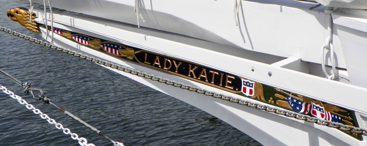
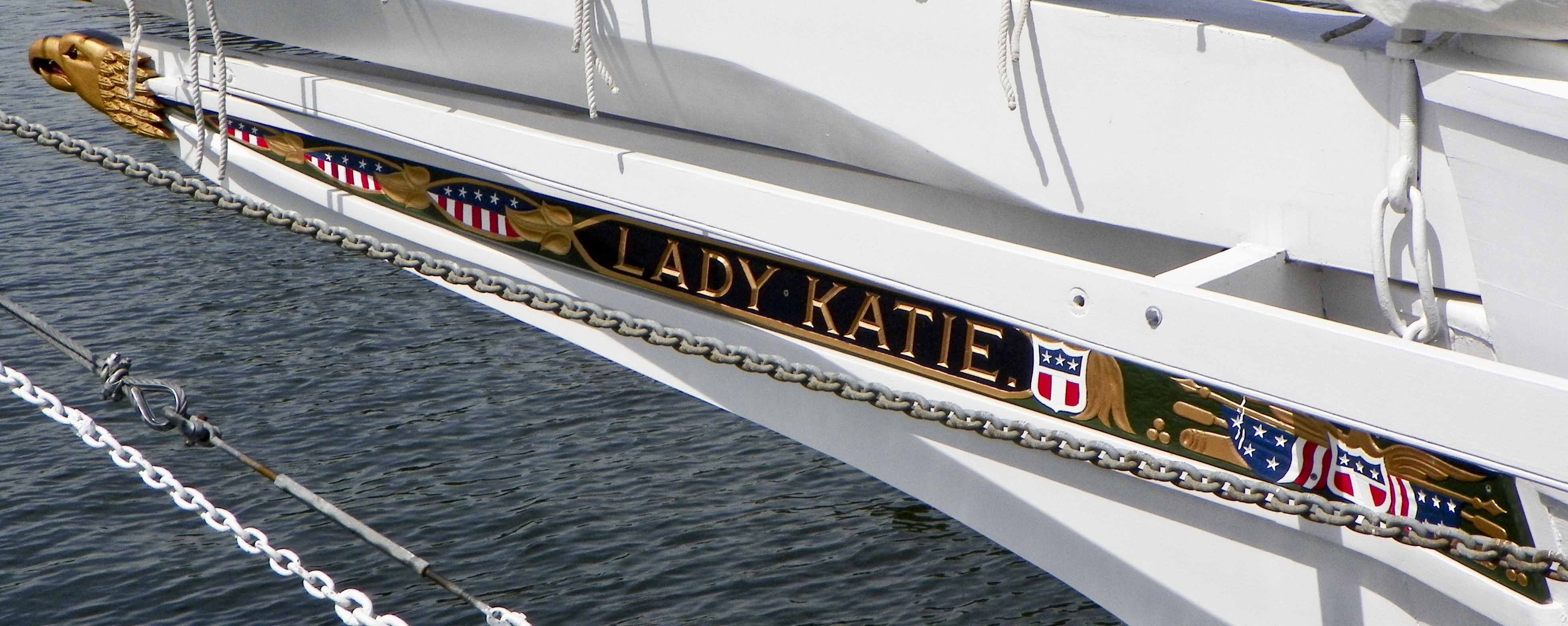
Determine the length using the drawn bore width as a meteric.
-
Cardstock for printers is about 0.011" thick, or about 1 3/8 thick in 1/120 scale, so you could use that as the sign, and just print the lettering on it. You can buy acid free cardstock, so it would not yellow on you, and would not need to be painted.
-
Fantastic work! These are at a fantastic level of detail! Have you tried Zipping/Compressing the STL file to reduce the size?
-
Great work! Thanks for sharing them!
-
In the model railroad hobby, they have been saying the same thing for over 60 years! This hobby will also survive.
-
I save my work several times during a session upping the "Revision" number each time (i.e. File_011.f3d, File_002....). This allows me to both not loose the last X (mins, hours) time of work, if the computer or program hiccups, (or a cat jumps on my keyboard), or I think of a better way to do an operation. And Yes, I have some of my projects that have run into hundreds of revision files. I can always delete or Zip them when I finish. Do not be afraid to go back and redo something, if you find new information/details during the design, or something you did does not print and fit like you thought.
-
3D Printing Cannons in Resin
thibaultron replied to thibaultron's topic in 3D-Printing and Laser-Cutting.
I run piece of wire or wood into the bore and touch hole to get any resin out, and print with the muzzles pointing away from the plate to encourage the resin to drip out. Holding the barrel in a pool of cleaner while cleaning the bore helps. I let the cannons dry over night, after final cleaning, before curing them. This allows any moisture in the barrel to dry, and not have liquid run out and mar the exterior surface. For larger scales I have an UV LED that run into the barrel, to insure the bore is cured. I think I detailed these steps earlier in this thread. -
Depending on how must saw dust or dust you are creating, several companies make ceiling mount units similar to this. https://www.grizzly.com/products/grizzly-hanging-air-filter-3-speed/g0738 I was lucky ans found a delta unit used for much less.
-
Bragdon Weathering Powders, are more expensive, but are made from finely ground real materials, like the Rust is finely ground rust. They also have a pressure sensitive adhesive, so will stay on the surface, and be less susceptible to being rubbed off after application. With any of these a light coat of flat clear should be concidered to lock the powders in place.
-
I would suggest using the window on the side as a guide rather than the door. I think the door is regular height, but narrow.
-
San Francisco cable car by kgstakes - FINISHED - OcCre
thibaultron replied to kgstakes's topic in Non-ship/categorised builds
If the real cars have them painted, I vote for that. -
3D Printing Cannons in Resin
thibaultron replied to thibaultron's topic in 3D-Printing and Laser-Cutting.
Here is a drawing, better showing the positioning of the transom on the axletree.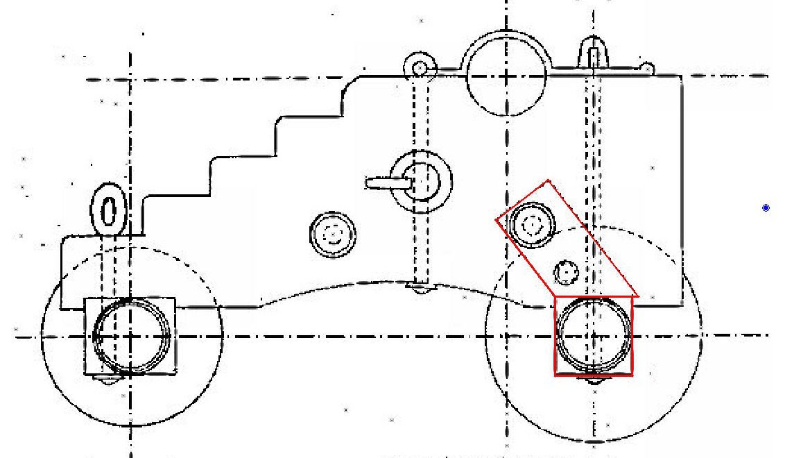
-
http://lastskipjacks.com/images/ladykatie_trailboard.jpg