


nickedw
-
Posts
33 -
Joined
-
Last visited
Content Type
Profiles
Forums
Gallery
Events
Posts posted by nickedw
-
-
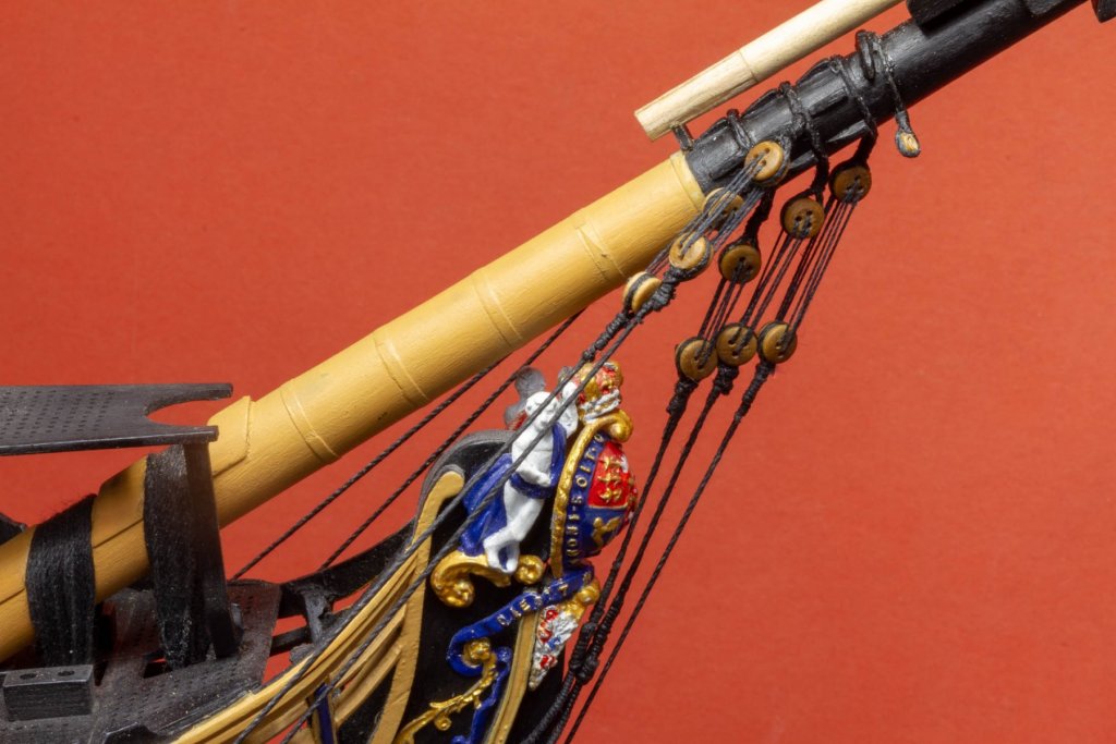
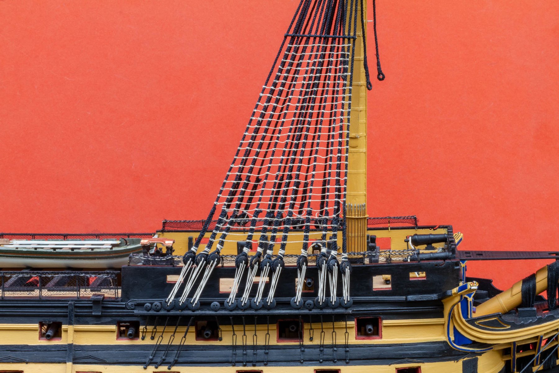
Took some outdoor photos of my baby-steps rigging progress as the sun is shining today.


- Robert29, mort stoll and zappto
-
 3
3
-
Hi everyone, I’ve been doing a bit more work on my Victory.
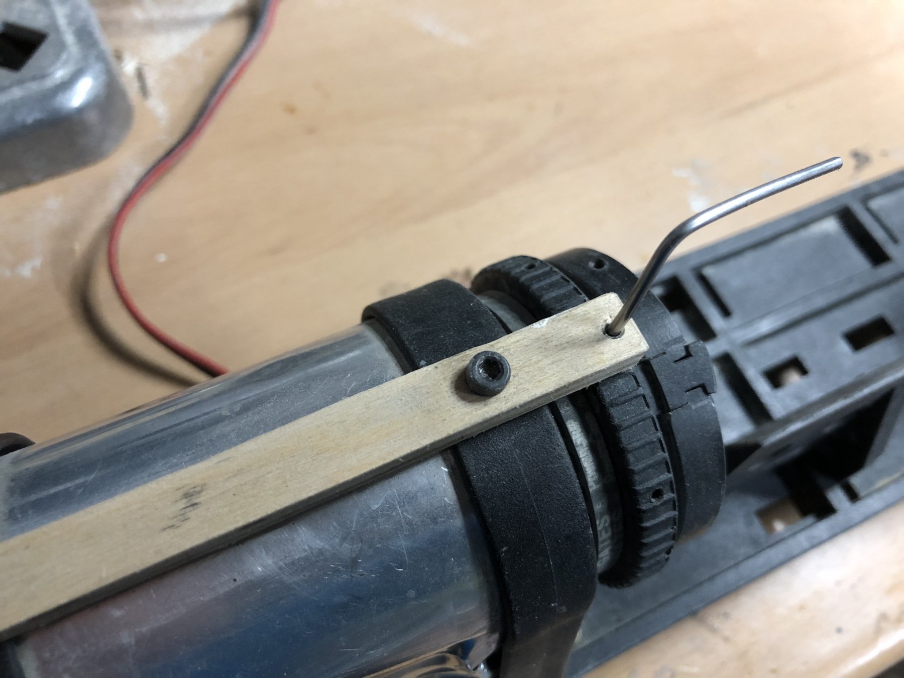
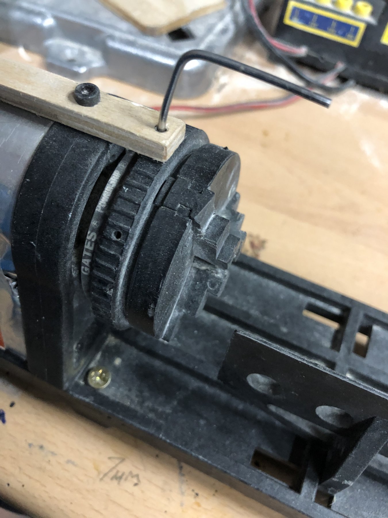
I was never very happy with my mast-making set up, I have a model engineers metal working lathe, and a little ‘toy’ mantua lathe I’ve never really used.
So I thought I would put some effort into getting a better setup.
The main issue with the mantua lathe, is it’s all made out of polycarbonate so the Chuck is a bit rubbish and doesn’t tighten properly, so long thin pieces slip, whip and destroy themselves.
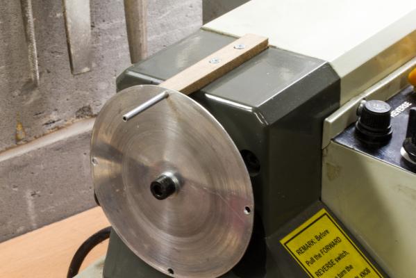
To cut a long story short, I decided to start drilling some holes in it...


So one in the tightening ring to get some leverage, with a steel rod inserted, which transformed it into a useful bit of kit from someting I was about to abandon, so while I was drill-happy, I also drilled 8 indexing holes and added a ply strip as you can see, that gave me the ability to cut squares and octangons easily as well as turning.
This works really well I think:


-
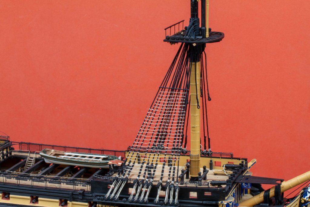
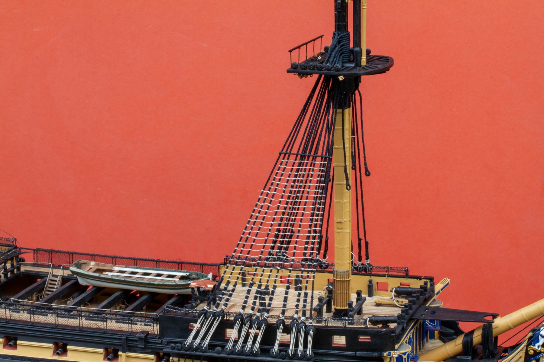
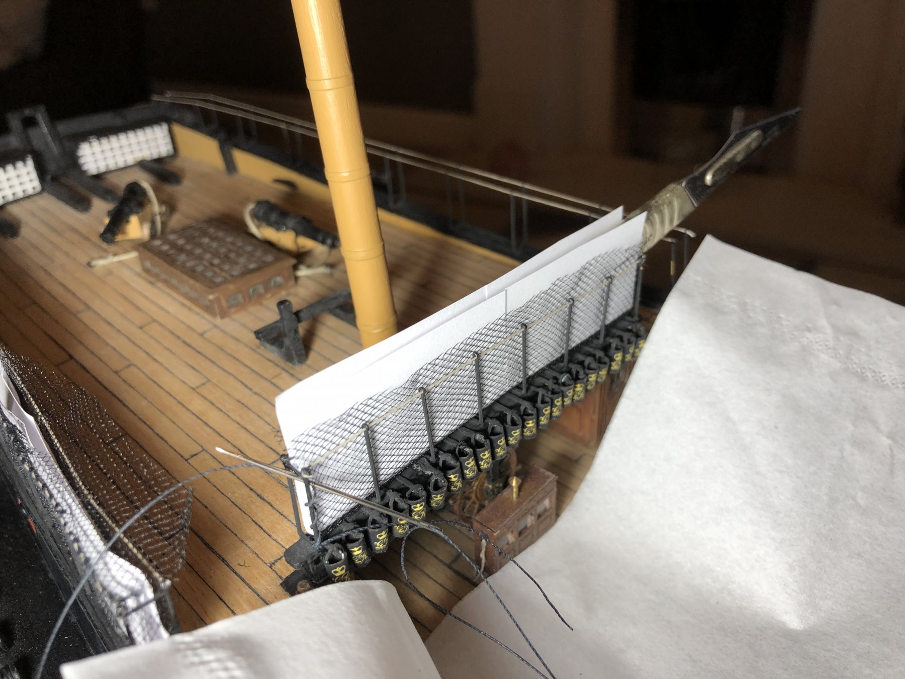
Been cracking on with the much-dreaded hammock-crane netting today.
Turns out it wasn't too bad. I developed a technique that uses a paper pattern cut and then folded to the shape the net needs to be. I then cut my tulle slightly larger than this, drop the both into the opening and weight down with a scalpel which is heavy enough and just the right shape to make the net conform. I then stitch one vertical end as below

Once a vertical end is stitched, I then fold the top edge of the tulle down and stitch the rest as below:-
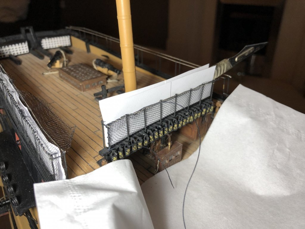
Finally seal everything with watered down PVA and trim the edges. I haven't trimmed the one in the photo yet in case you're wondering)

The paper makes it conform to shape, gives a high contrast (and isolation of the work) and acts as a guide for the needle. So it turns out a job I've been dreading wasn't that bad in the end. I've also discovered how useful draping a tissue over sticky-out stuff is to prevent snags when sewing stuff like this is!
-
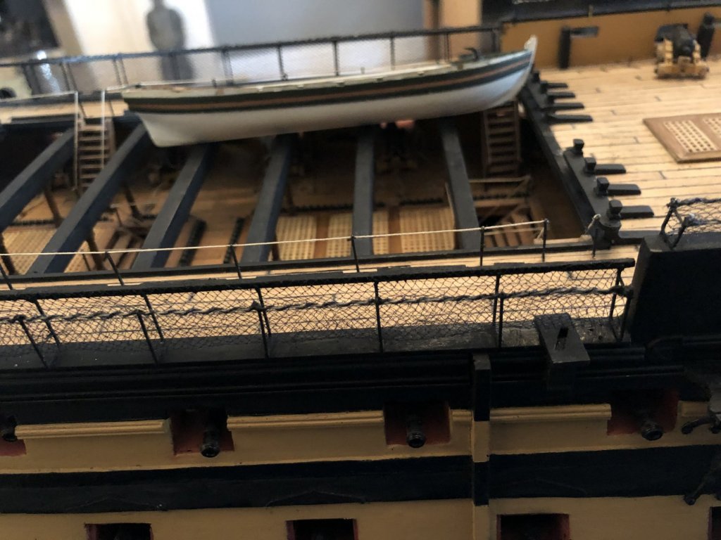
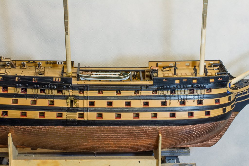
Made a start on the rigging now (Eeek!) so took a few shots of general progress today. Also cracking on with the hammock netting which I have really been putting off.

- GrandpaPhil, Robert29, Richmond and 3 others
-
6
-
After a very long lay-off, I'm back on the horse now and enjoying my build.
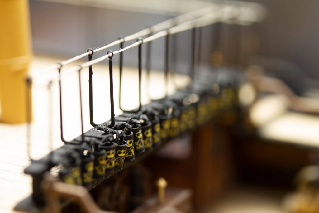
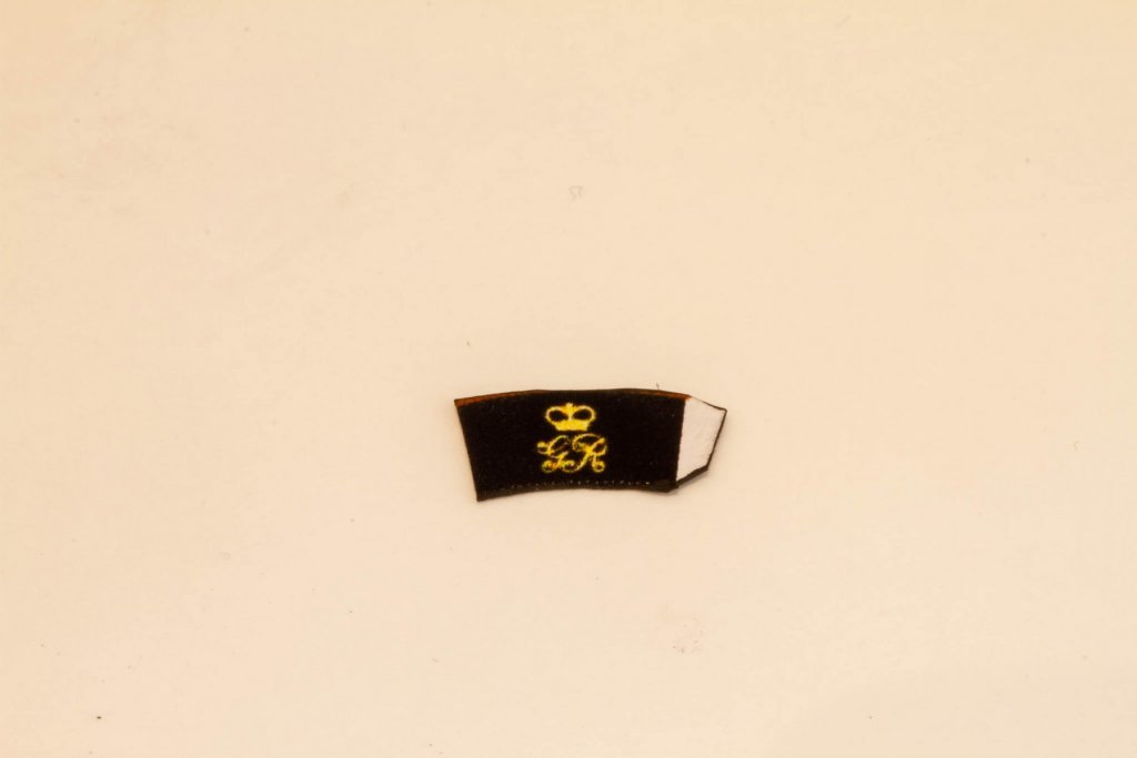
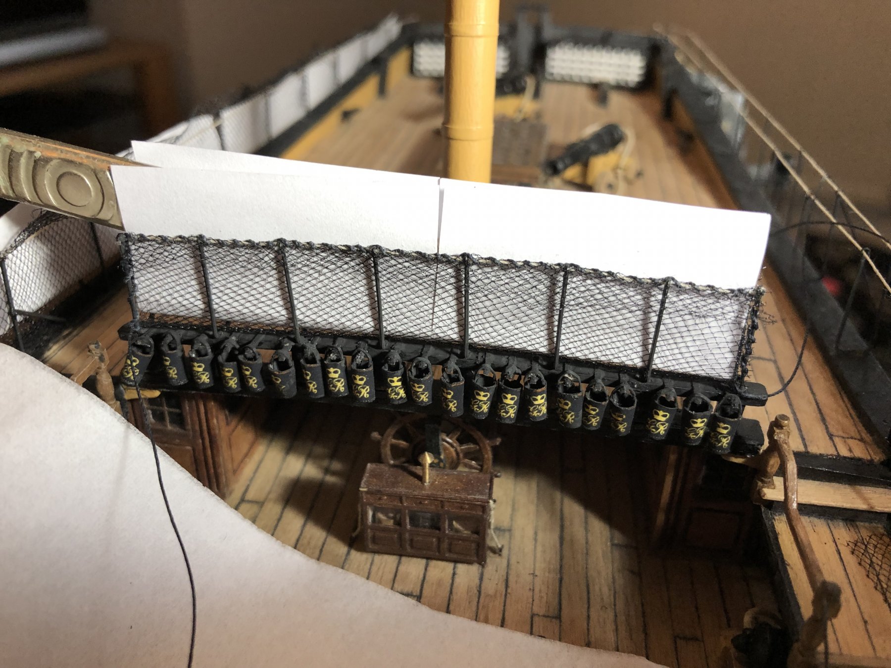
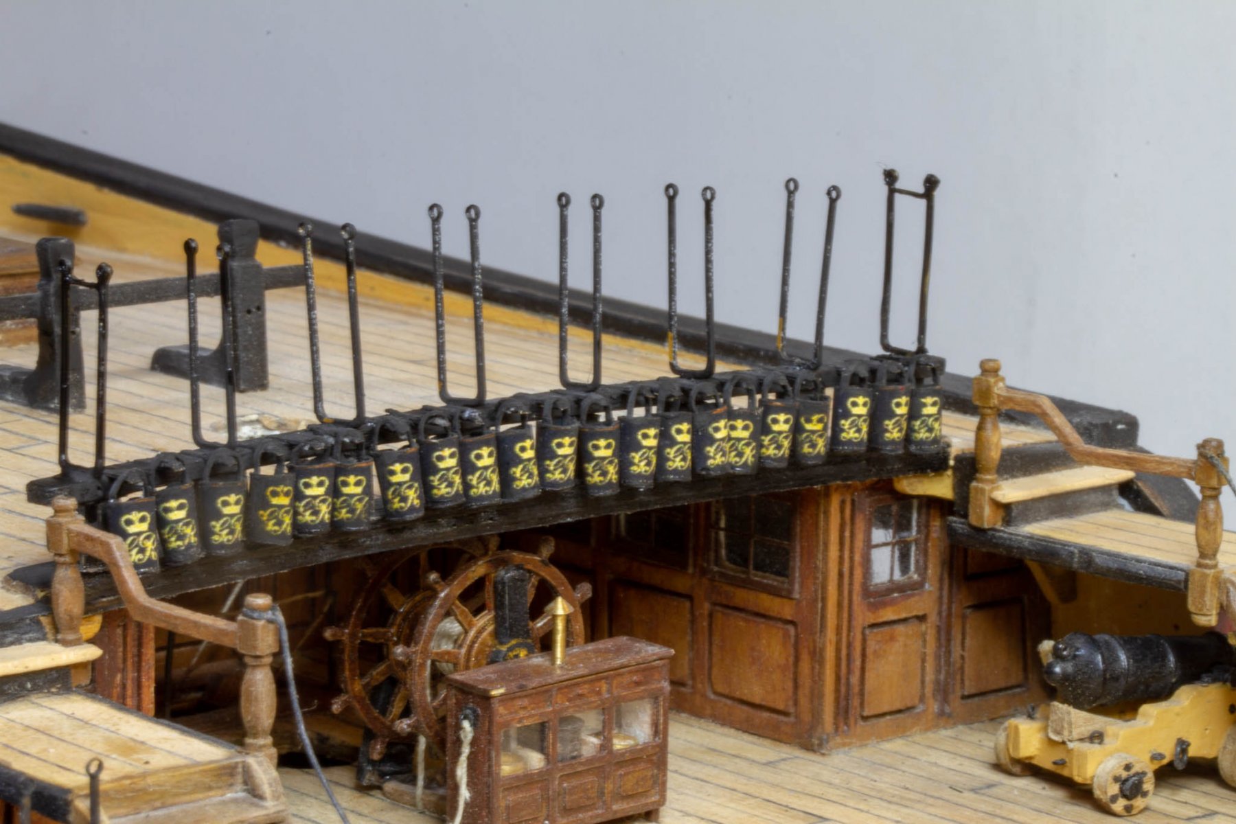
I've never been happy with the turned brass buckets provided in the kit and the real items are very distinctive with the GR coat of arms.
Nobody I can find seems to make a decent after market replacement for these, which is surprising as I think they are very noticeable and unrealistic if left plain.
So I've been considering 3D printing or making some Photo Etch, both of which I've done in the past for other projects, so I have some experience in this area
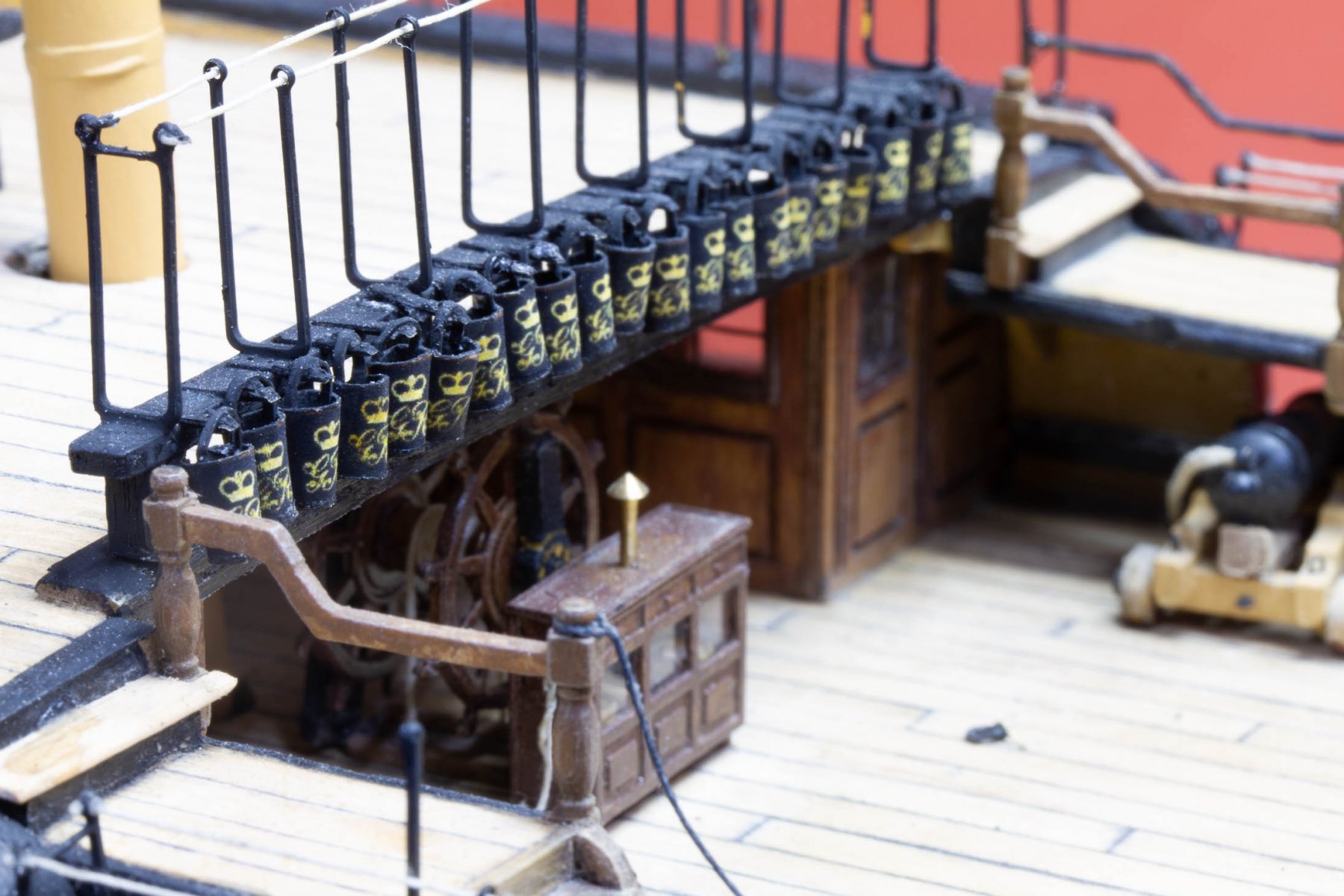
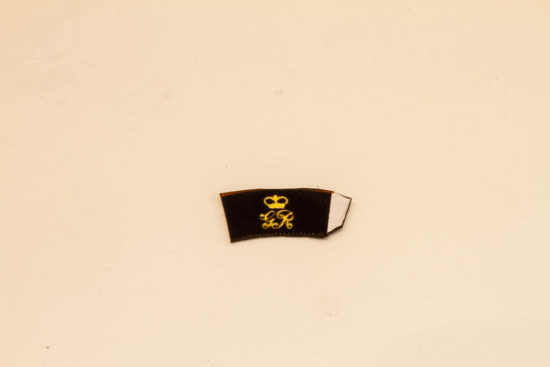
In the end, I've gone for the simplest solution of ink-jet printed cartridge paper, and I think, they look OK:-

I've attached the illustrator file I created in pdf format, if you want to use it - PRINT AT 10% OF FULL SIZE, max dpi your printer is capable of and use good quality matt cartridge paper, not gloss photopaper.
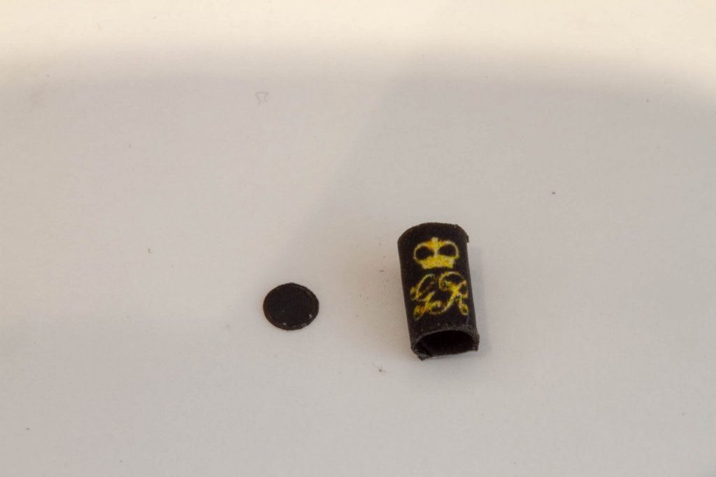
When you have everything cut out, paint the back and all edges matt black first, leave a tab on one end to make the joint, like this:-
Form the curve, by rolling around a metal rod about 60% of the diameter of the finished bucket.
For the bottoms, I used the smallest size on my rotary punch tool to punch out cartridge paper disks, paint the paper black first as it's difficult to paint the inside of the bucket bottom!
The handles are just thin strips of cartridge paper, again painted black. on all edges. This is easiest to do when attached at both ends it turns out.
- Richmond and Landlubber Mike
-
2
-
Hi Robert
I think my brass tubing was about that in diameter, check the inside diameter.
The wiring was a tight fit and I used very special wires.
I doubt that you will find normal wires to go through.
The ones I used (from work) are Kapton coated wires, the Kapton is a good insulator so is applied very thinly.
A search online should find you a local supplier.
Nick
Robert & Nick,
I use enamelled wire for jobs like this (the stuff of transformers and other wound components) which is as thin as you like.
If you're really struggling, you only actually need one wire if you use the brass tube itself as the other conductor.
Nick
-
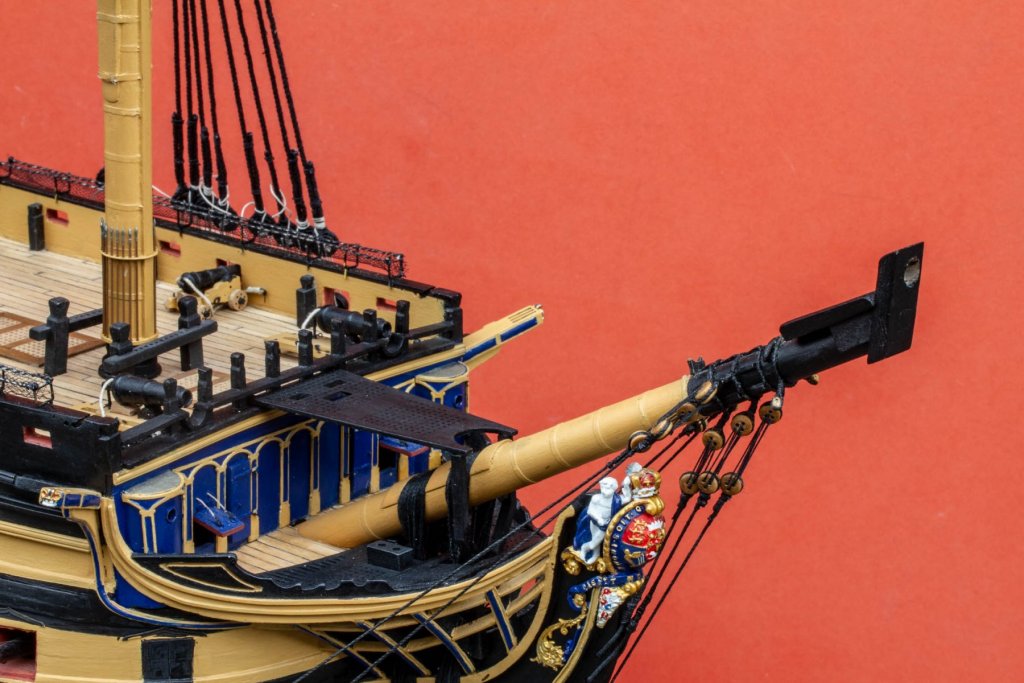
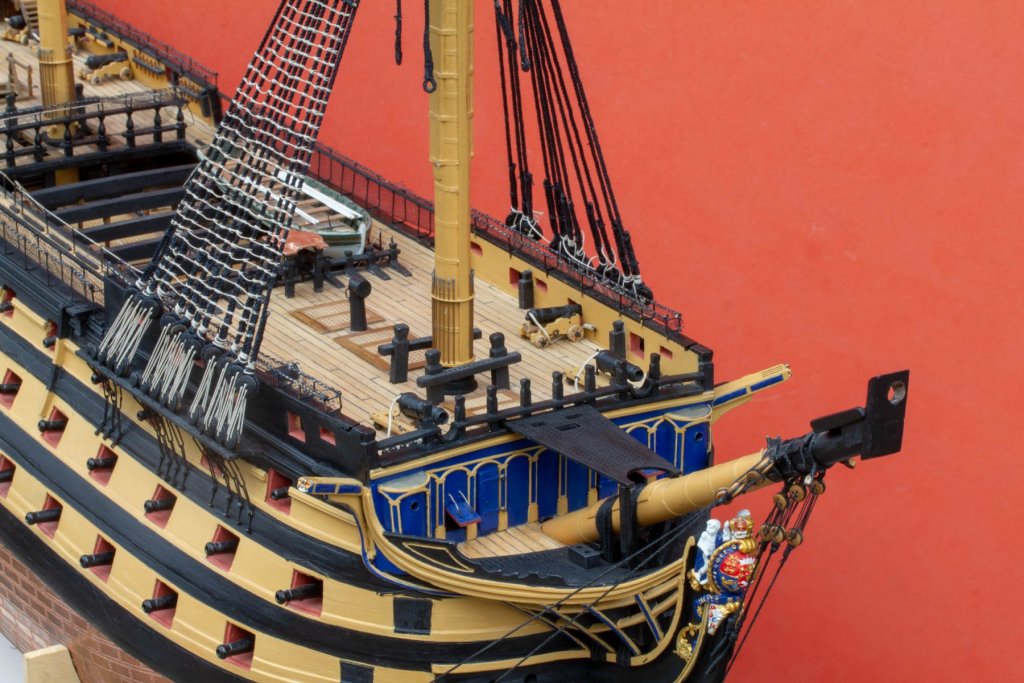
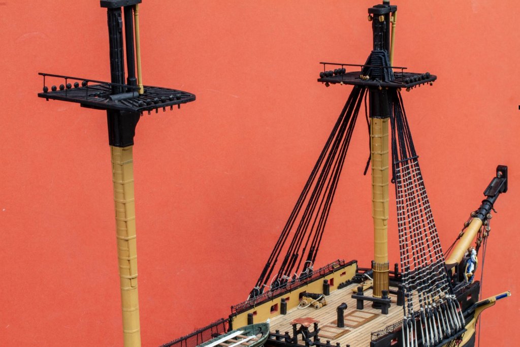
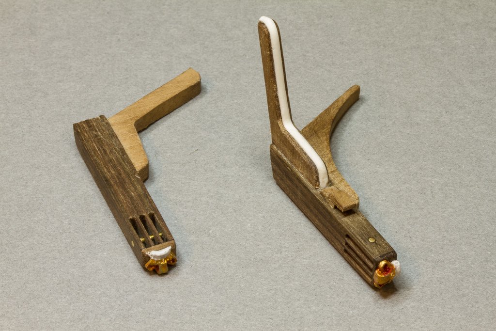
although I'm very much a dog person, I must admit I did enjoy building the catheads:-
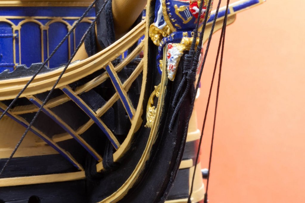
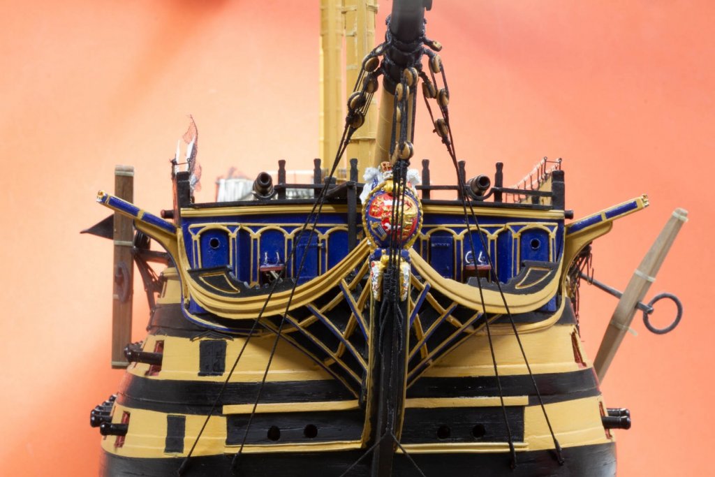
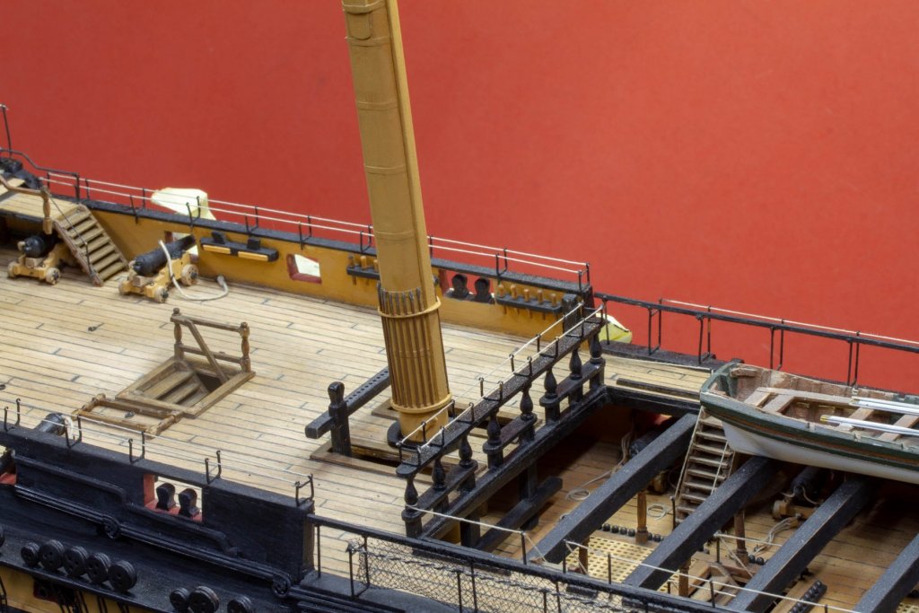
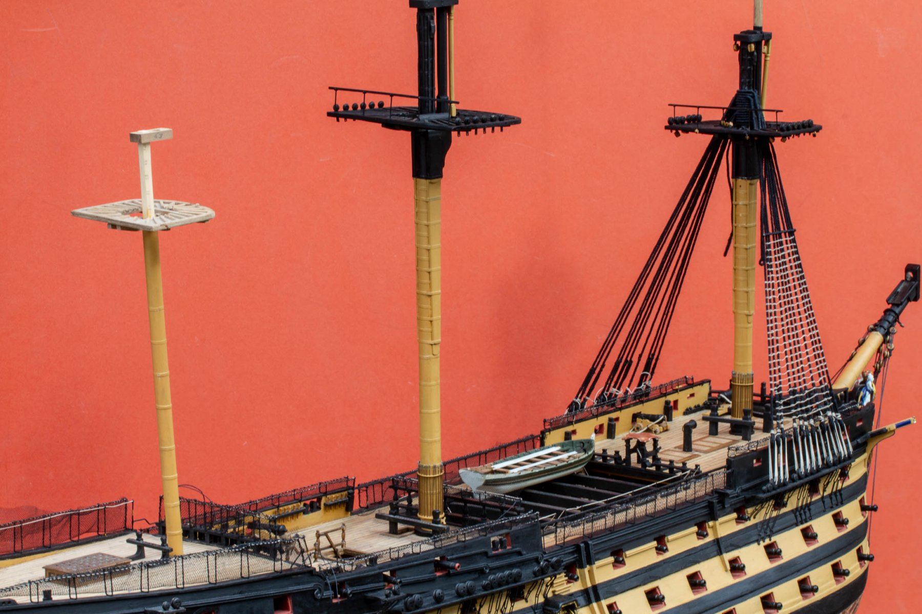
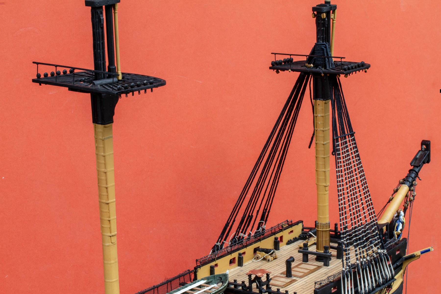
Here's a few general views of progress - A long way to go!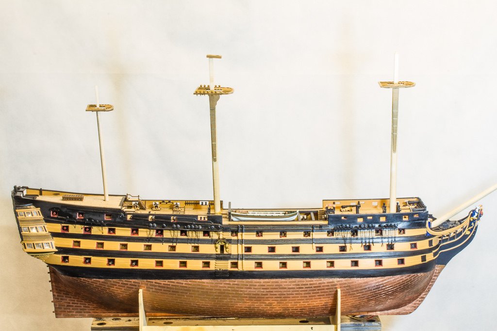
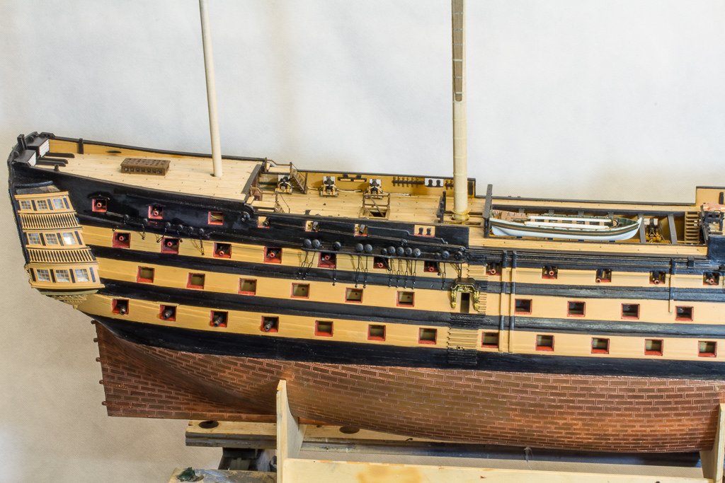
Thanks for looking,
Nick- mort stoll, Robert29, waspy and 1 other
-
4
-
Been doing some work on detailing the poop deck ladders - it's looking very dusty now I look at the shots!
Added some plastic sheet profiles to the cheeks of the ladders and frames, chamfered the edges and dry-brushed (a bit too much looking at it) to pop the detail.
Nick
-
Whilst I'm at it, here's how I make rings for the many eyes on the vessel.
I use black coated florists wire and form around the shank of a drill bit for varous sizes as appropriate
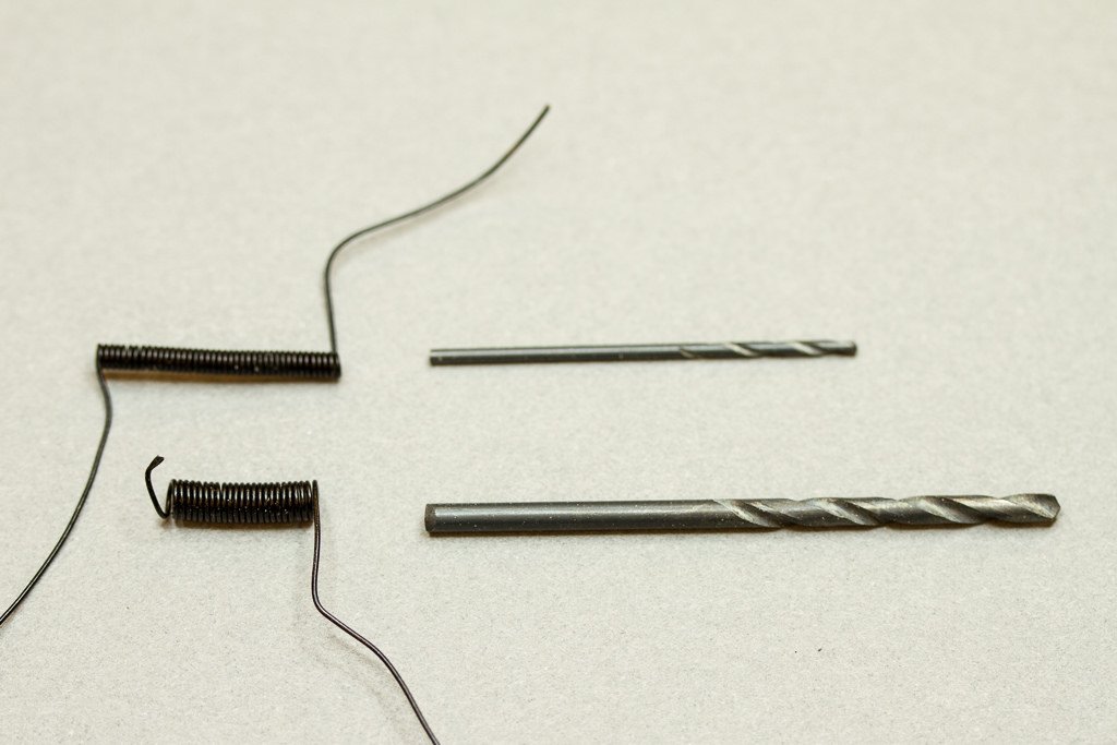
I find cutters fail using the extreme tip all the time, so I have ground down the top jaw of some cheap flush cutters designed for printed circuit boards (the bottom jaw is still full length to locate it the wire)
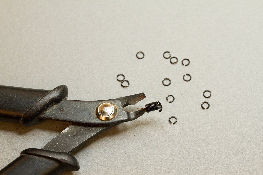
This gives me rings (more or less) with a handy gap the right size to insert into kit eyelets
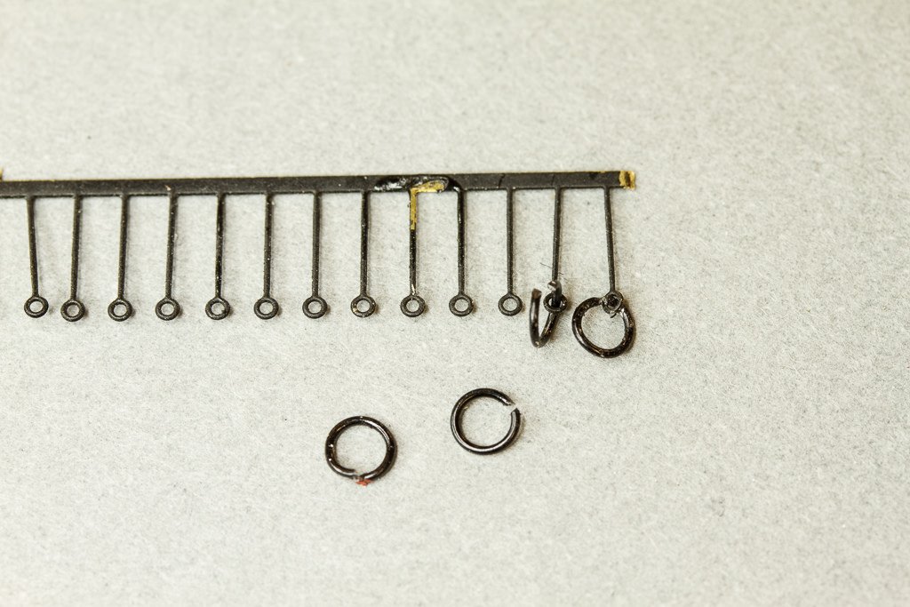
Just flatten them when inserted, and close up the gap with pliers. I then re-spray with matt black to remove any scratches and marks caused by assembly..
Here they are in use
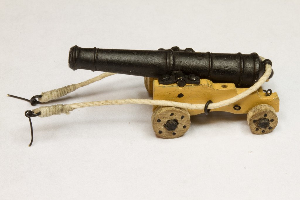
Regards,
Nick
- Seventynet and mort stoll
-
2
-
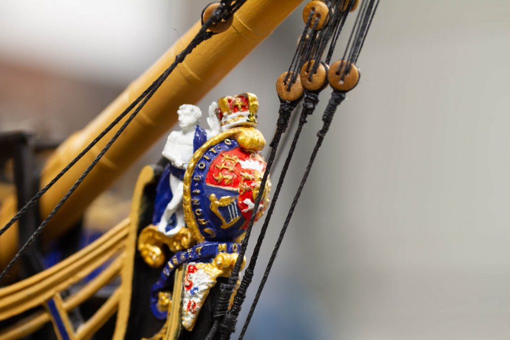
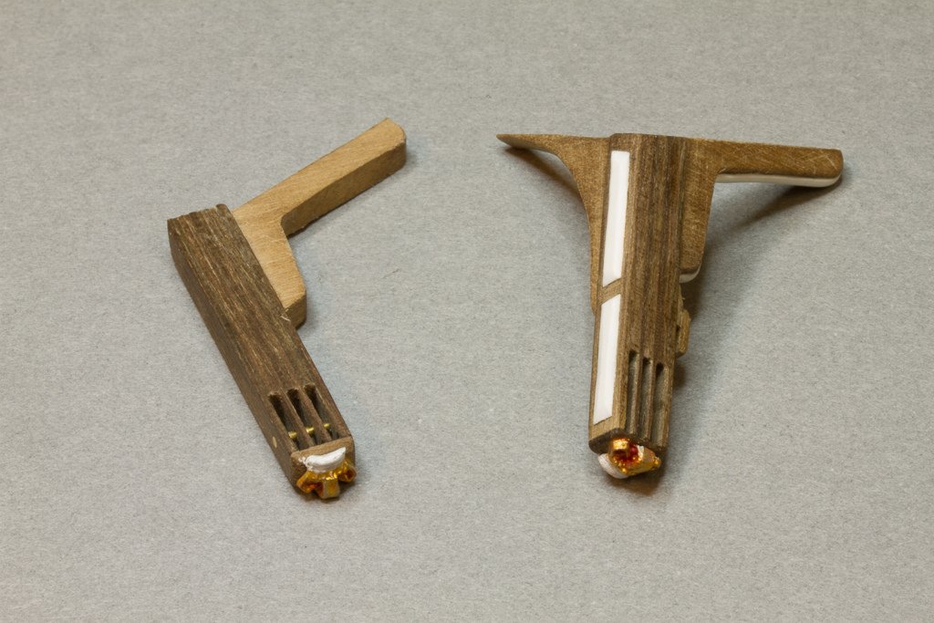
Hi folks, bit more activity and I thought I would show how I made the scrolls, as I have more to make for the second side of the ship. I had considered making resin casts but as 6 of the 8 required are unique I decided it wasn't worth it.
Anyhow, here' what I do:-
Firstly I use an excellent rolling tool designed for forming cylinders from photo etch material. This is one of those expensive modelling tools that you agonise over buying but then proves invaluable on the times you need it so never regret purchasing.
It's a nicely machined alloy base with a set of rollers that match each half cylinder cut-out, I formed a couple of test pieces to show what's it's really designed for.
So what I'm doing is using some lead wire (solder actually in this case)
dropping it into the smallest C channel,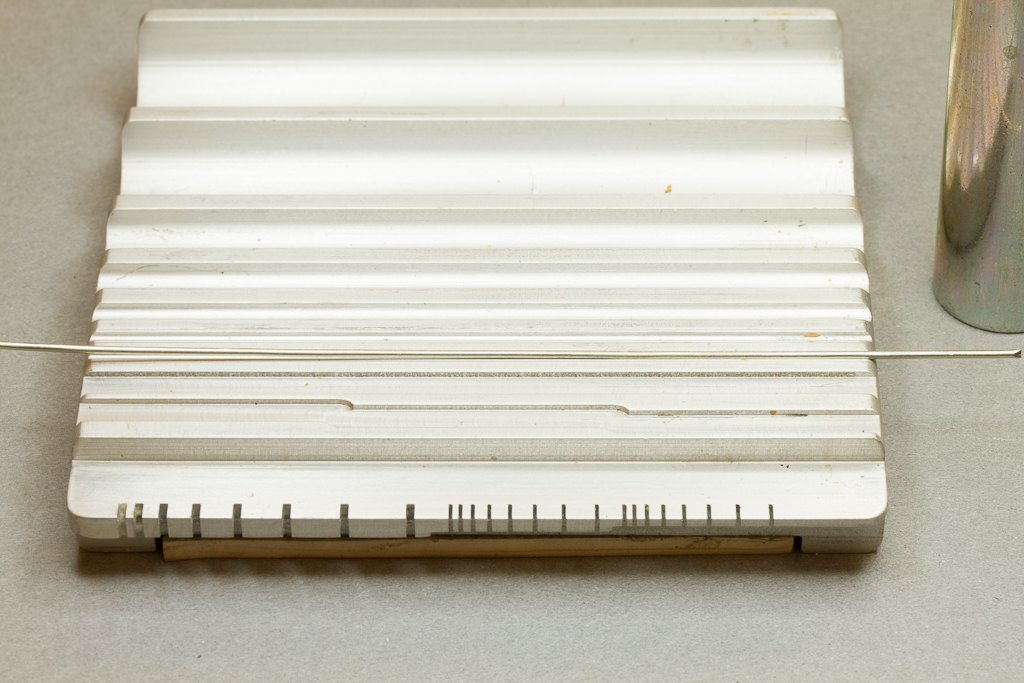
then using the largest roller to compress it into the form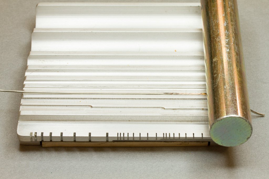
like this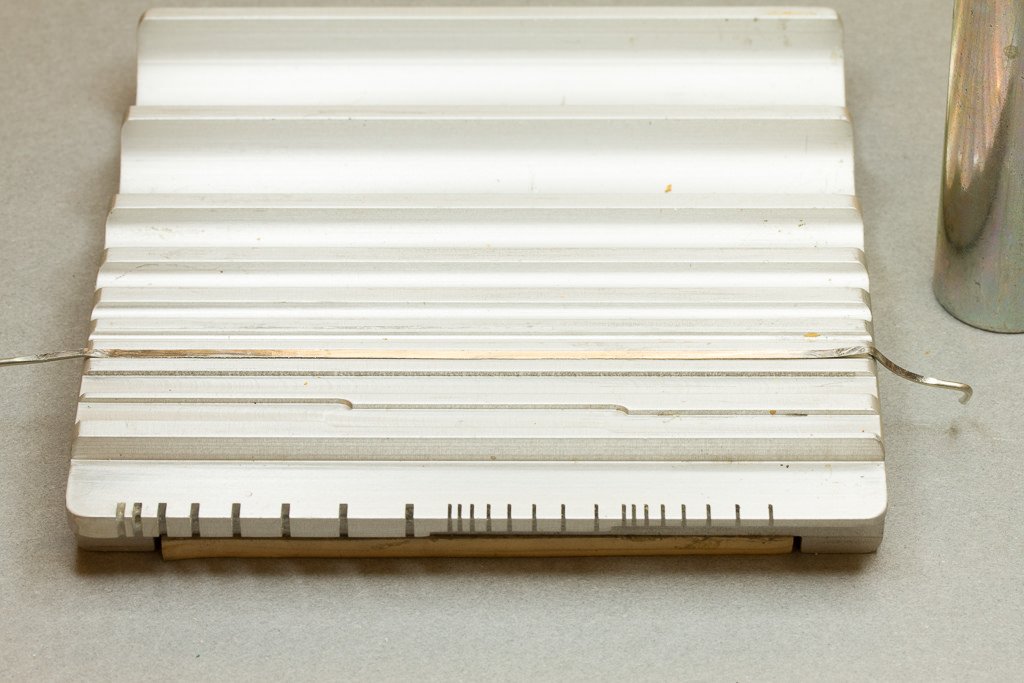
and ending up with a nice D section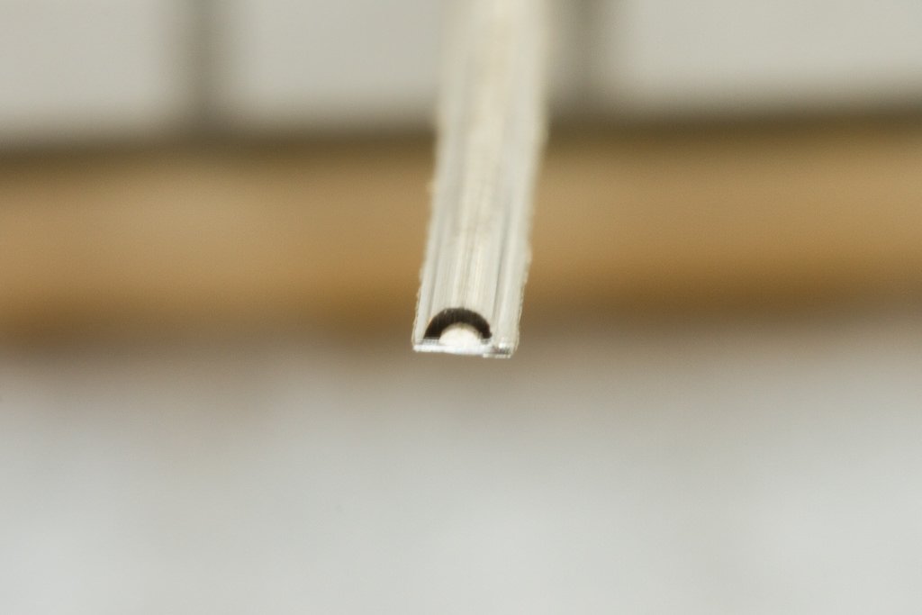
There is excess material, flash, on either side, just scrape off with a scalpel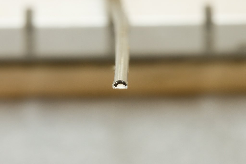
I use the wooden kit item as a template for plastic sheet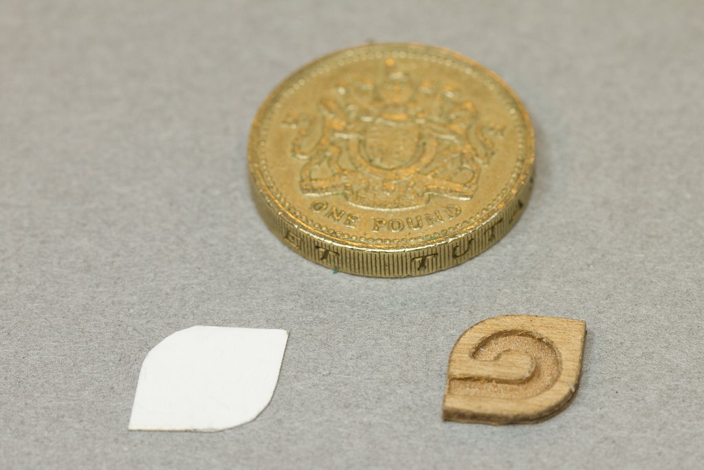
and carefully form the D section onto the plastic template with the flat to the back of course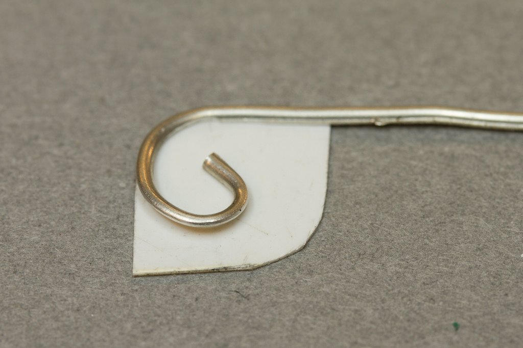
I then use plastic rod as the centre piece and form the second rail in the same way, hot CA when happy with the curves and intersections.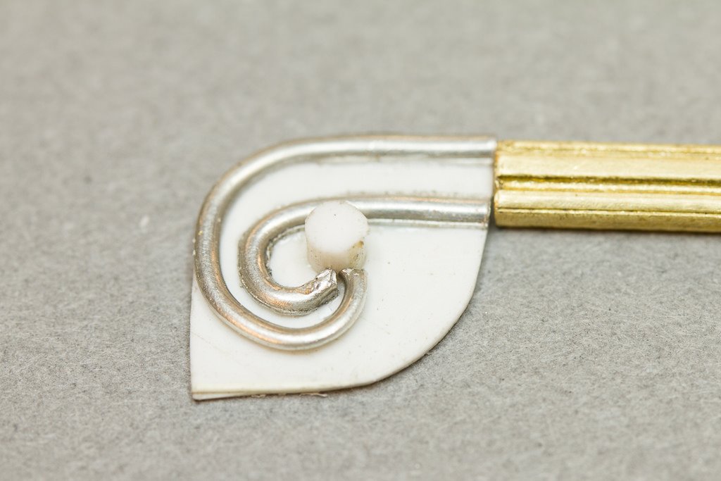
Finally I heat form some plastic strip (chamfering the end) to fill the void and with a sanding board, reduce the height of all the plastic to match the lead work. Tamiya thin cement takes all the 'noise' out of the plastic - scratches, nicks etc.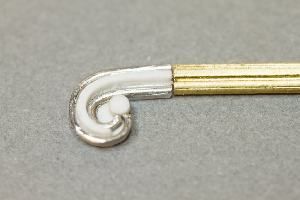
Lastly, Mr surfacer is your friend to ensure everything is smooth and blemish free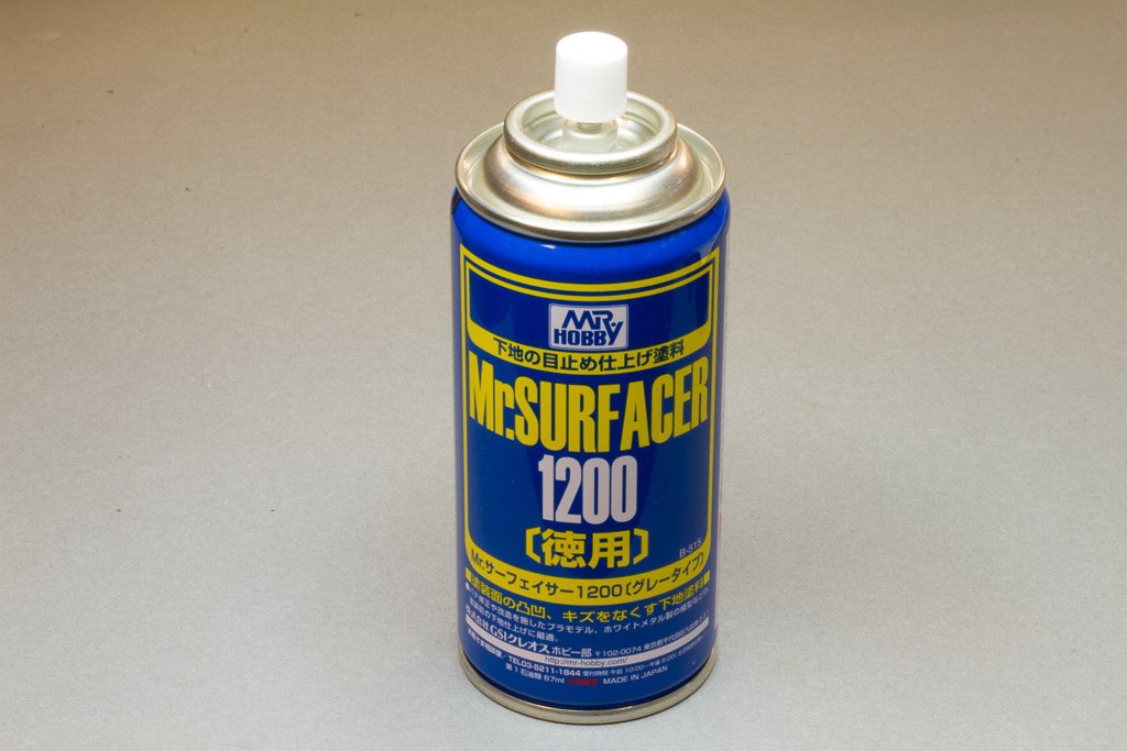
And that's it. MAtches the prfolie of the brass section fairly well I think and an improvement over the kit item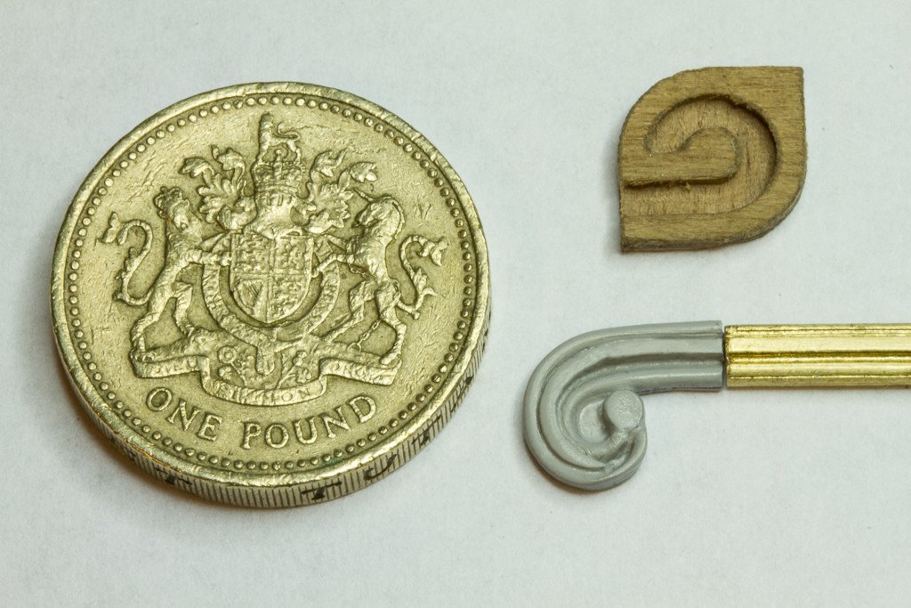
Here's the real thing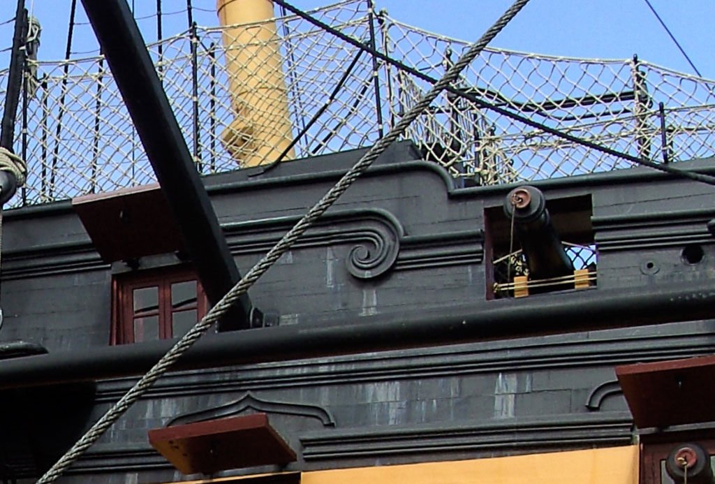
and the model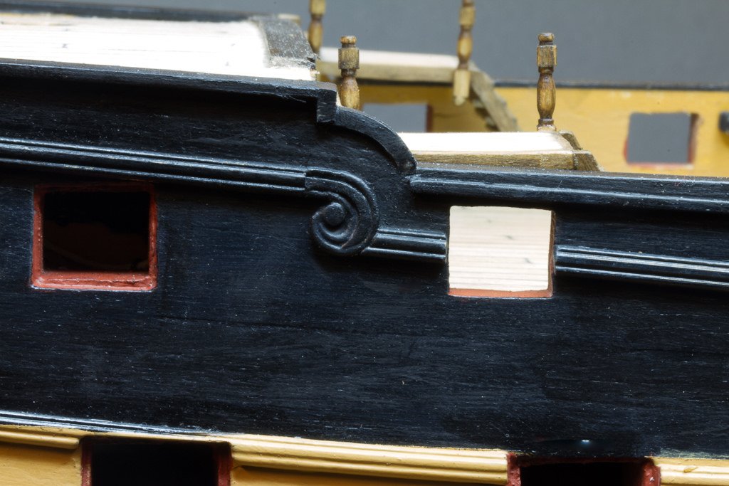
Hope this may be of use to someone!
thanks for all your support with the build,
Regards,
Nick- mort stoll and Seventynet
-
2
-
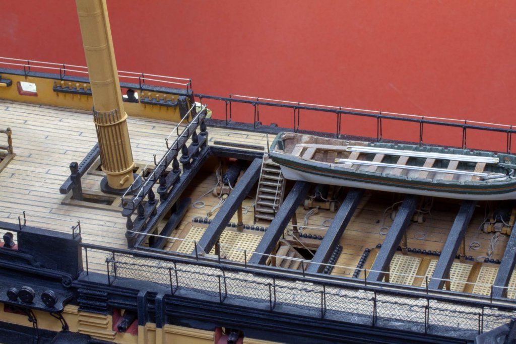
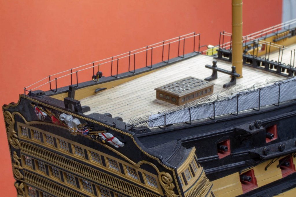
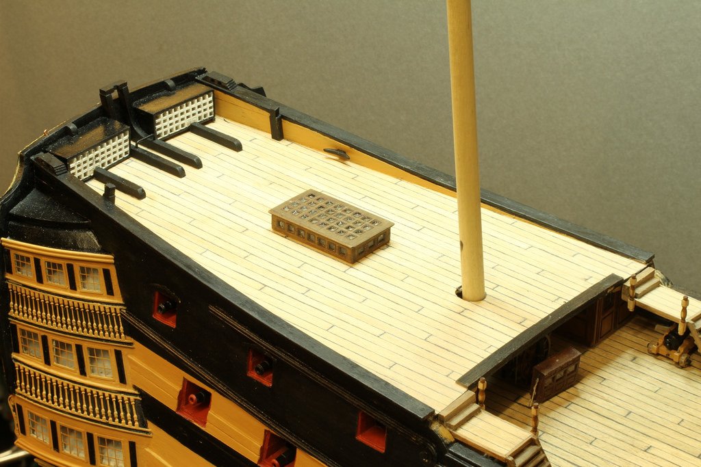
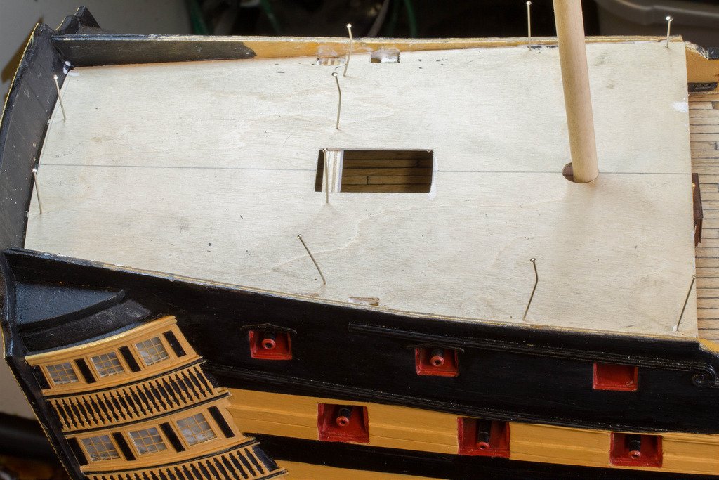
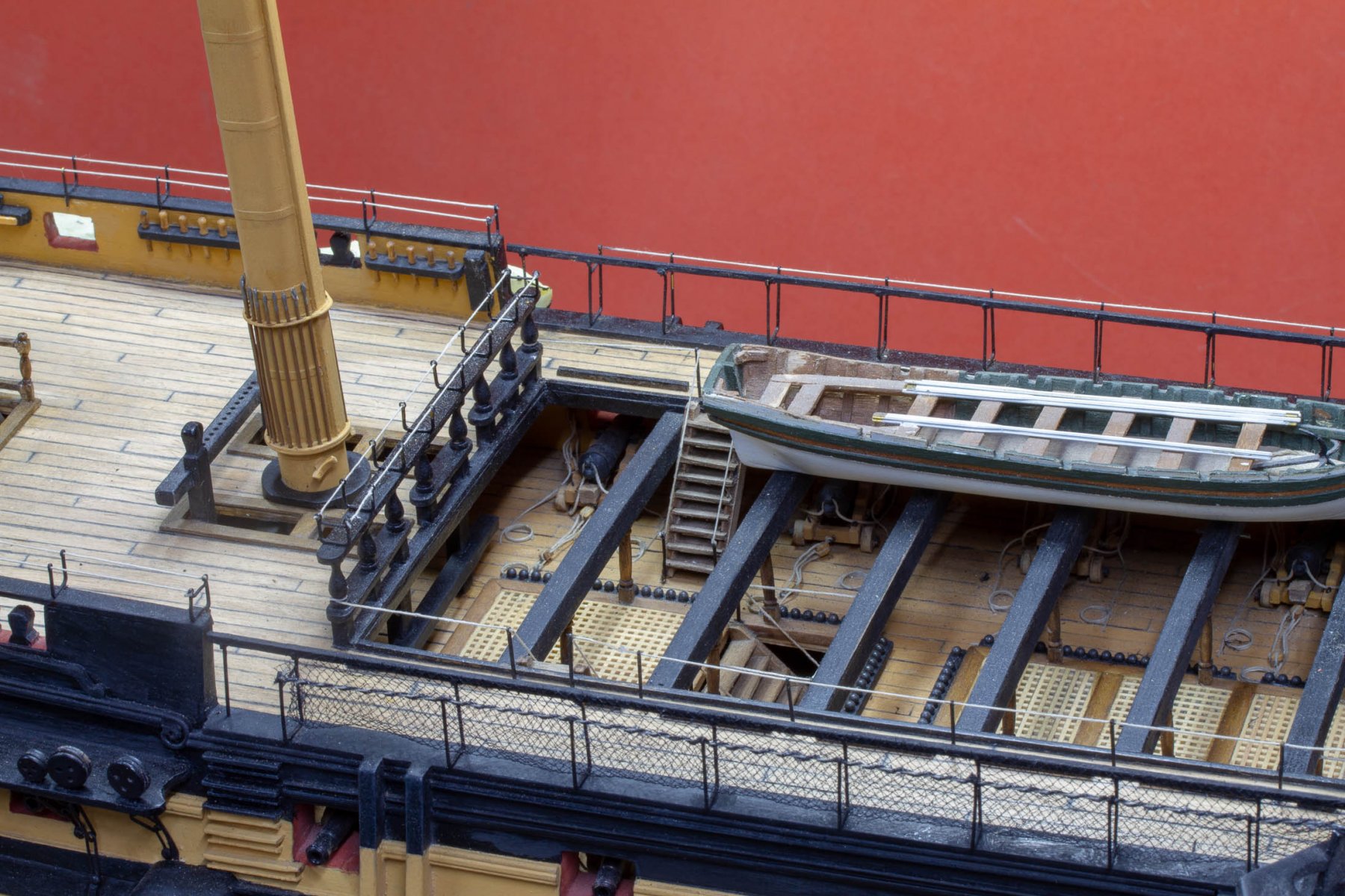
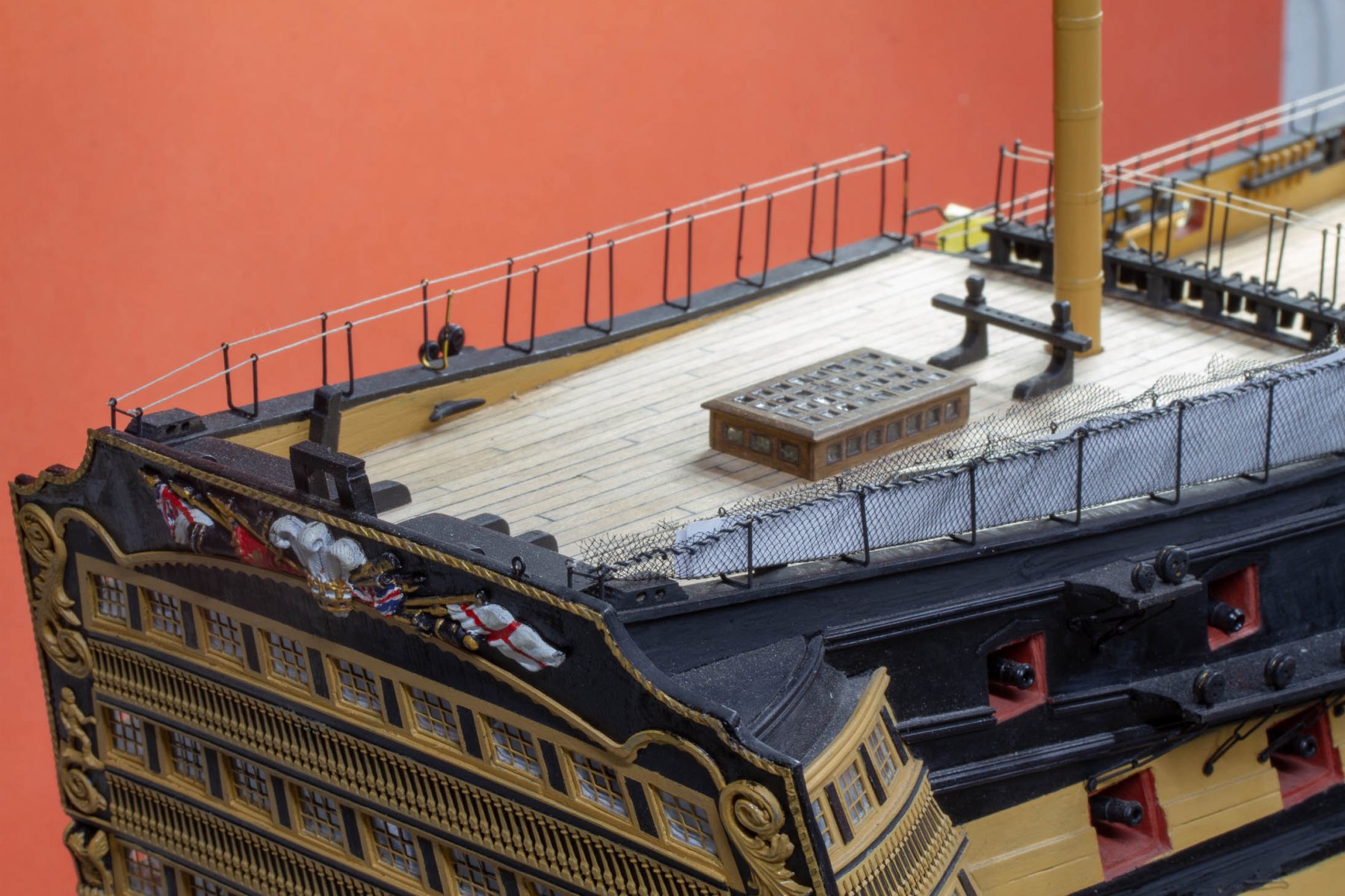
Got a little more work done this weekend, planked and capped the poop deck, installed the flag lockers and knees,built the two platforms and ladders, although not fitted yet.
- justsayrow, Seventynet, mort stoll and 2 others
-
5
-
Amazing build, very impressive, although a slightly depressing reality check on how much is left to do on my own build!
-
AS I had already prepared the planks, the deck went on fairly quickly:-
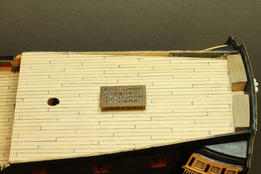
I had already built the skylight and flaglockers.
The skylight is glazed with glue'n glaze for that hand blown glass look.
Nick- mort stoll, Tadeusz43 and Seventynet
-
3
-
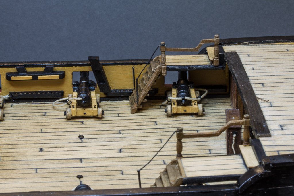
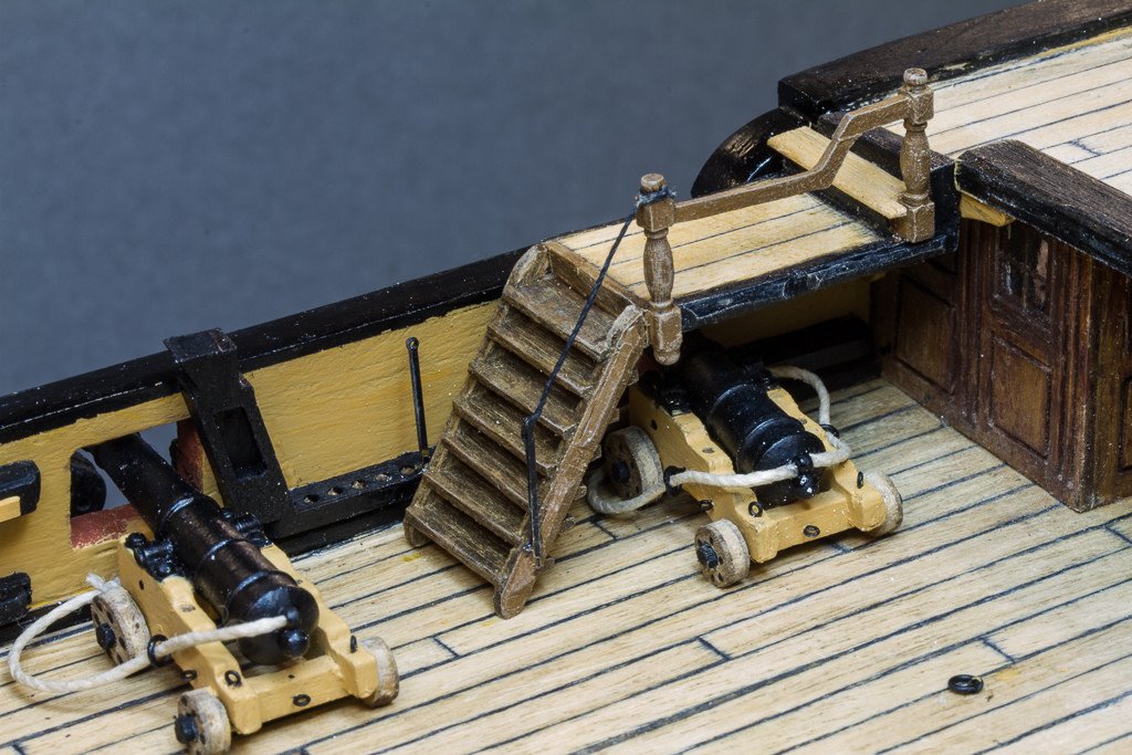
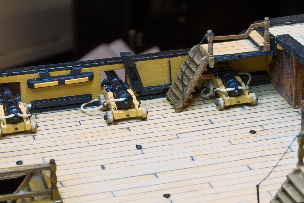
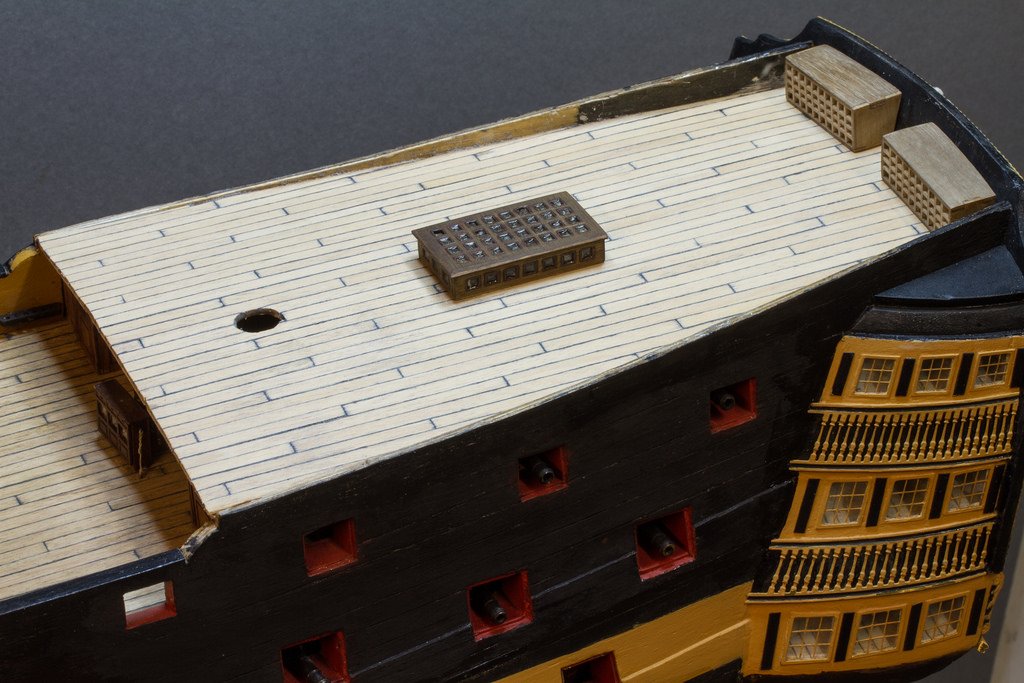
So I just went for the main rigging on the 'hidden' guns in the end. I think this is a reasonable compromise


The deck is fitted now anyhoo.
A little bit more deck to do then the fun with string really begins.
Nick
- Tadeusz43, GuntherMT and Seventynet
-
3
-
I've decided to compromise and partially rig these six guns, as the training tackle won't be visible under any circumstances I've decided to omit it. Pictures to follow.
-
Well Winter is here, so time to dust the old girl off. Lots of progress, but not many photos during construction I'm afraid.
Here's where I'm up to:-
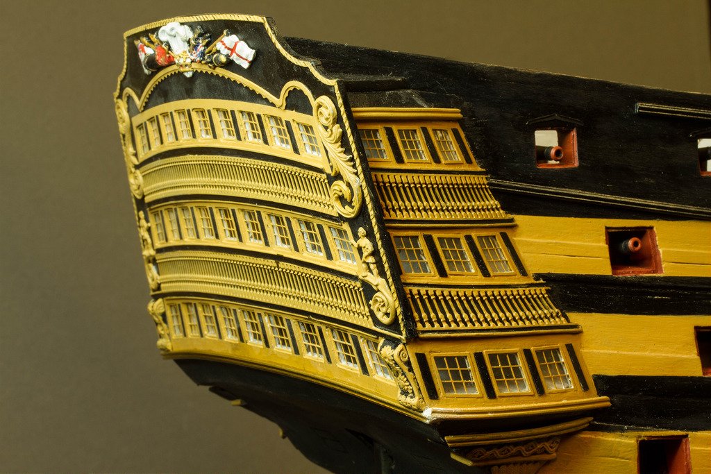
Finished Glazing all of the gallery now,
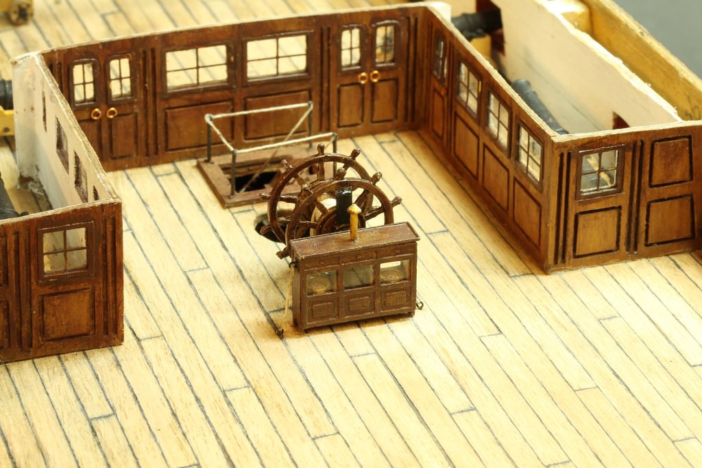
Scratch built the compasses and lantern

Scratch built the scroll work for the mouldings by forming lead wire into a D channel and curving onto a plasticard backplane.
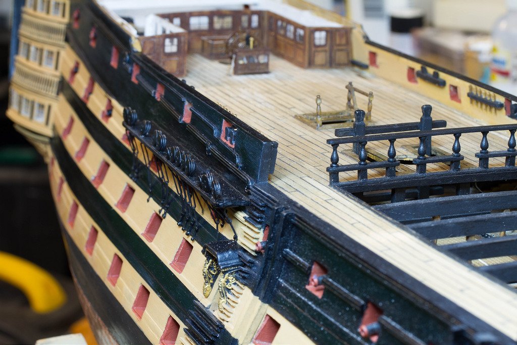 built all the chainplates, soldering the links for strength, and fitted the first one.
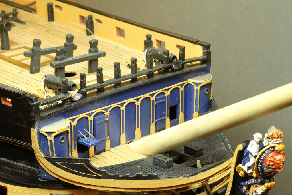 Caronades rigged.
More to follow.
Nick
- mort stoll, Seventynet and GuntherMT
-
3
-
..., the Arizona is that plastic?
Yes it's the 1/200th scale Trumpeter kit with the KA models deluxe accessory set (laser cut veneer deck and lots of photo etch) it also has correct brass props added.
The photo etch set costs about the same as the kit. Well worth it though.
Nick
-
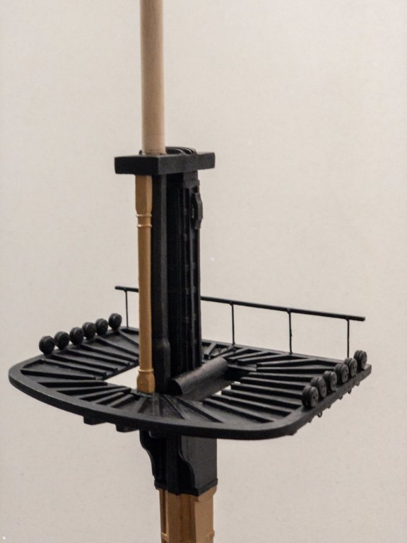
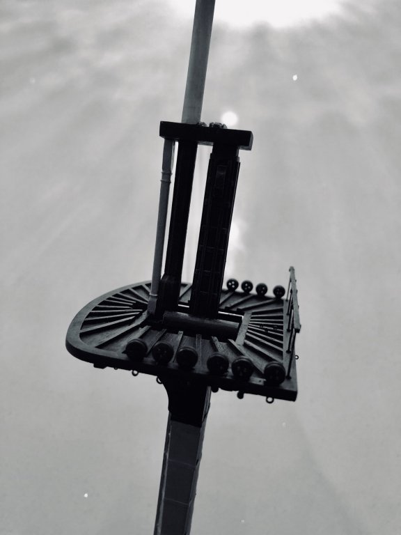
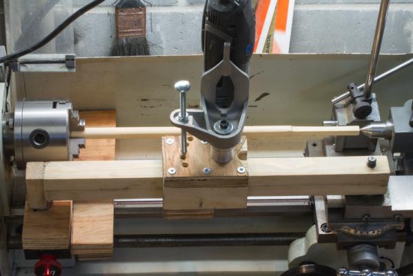
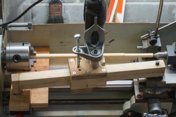
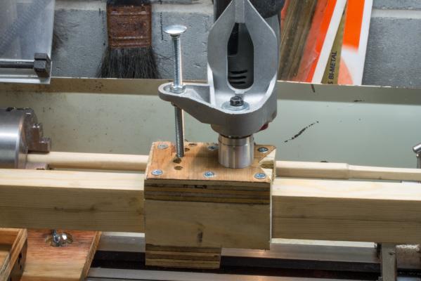
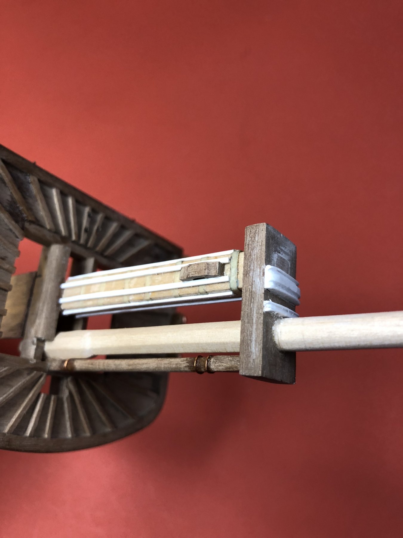
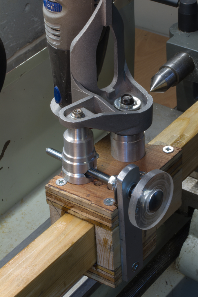
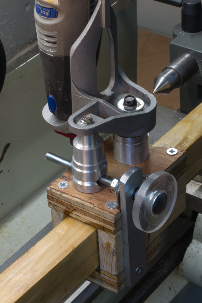
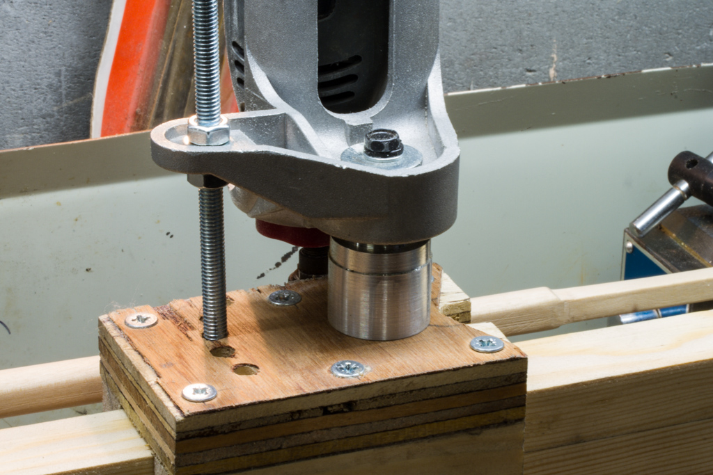
Hi all modified my tool so I can continuously vary the travel of the cutting head. This is a much better arrangement than my original index idea as you can see.
Original MKI Setup:-
MKII enhancement
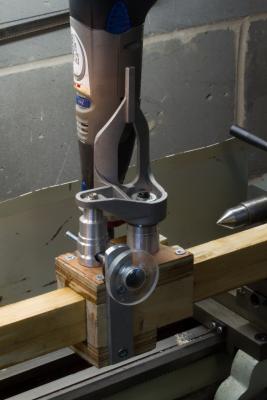
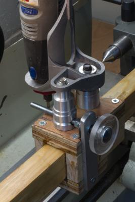

This makes multiple passes much easier, maintaining a constant angle.
It has a floating nut captive in the new machined pillar the adjustment screw is sandwiched between the flat plat with spring washers to allow very slight pivoting as the screw is worked. The knob is just turned from scrap acrylic sheet I had lying around in the workshop.
I know it all should be linear ideally, but it works well enough for the application in hand.
Thanks for your continued support.
Nick
-
-
what are you using as the straps?
I have some masking tape of the right width and thickness, sealed with Matt varnish.
Probably not the 'done thing' but seems to work OK.
Nick
-
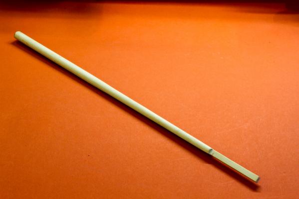
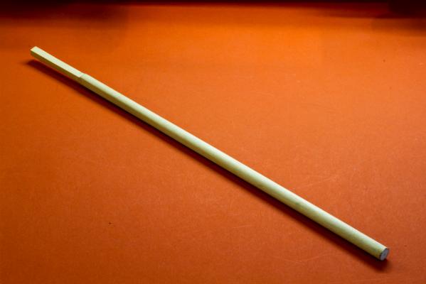
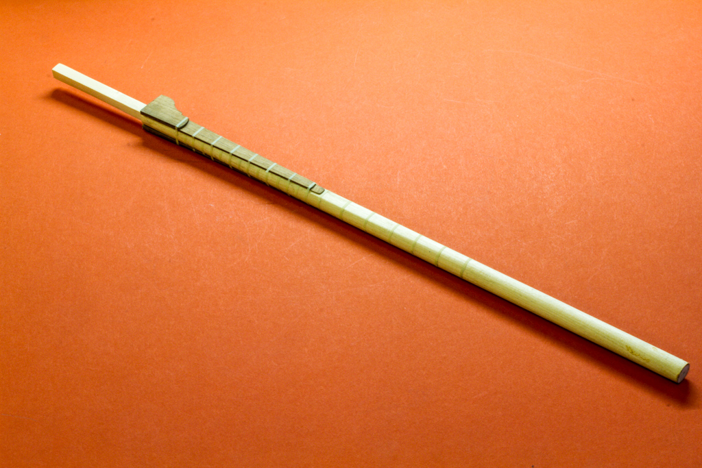
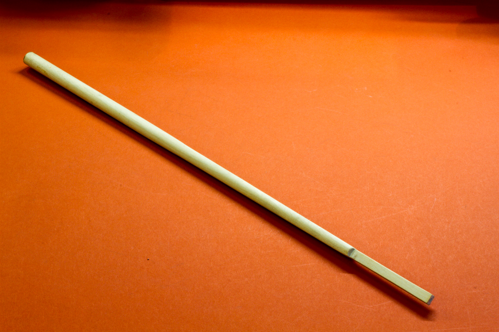
And here's my first mast using my new setup:-
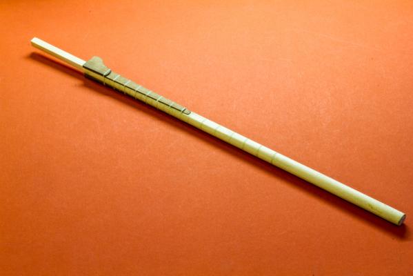
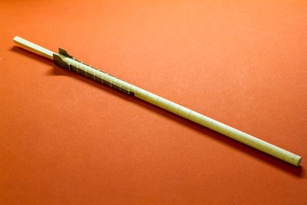
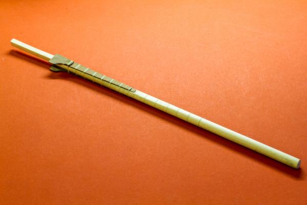
Regards
Nick
- Landlubber Mike, Kevin and gieb8688
-
3
-
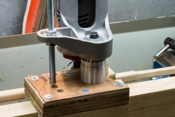
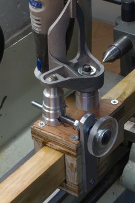
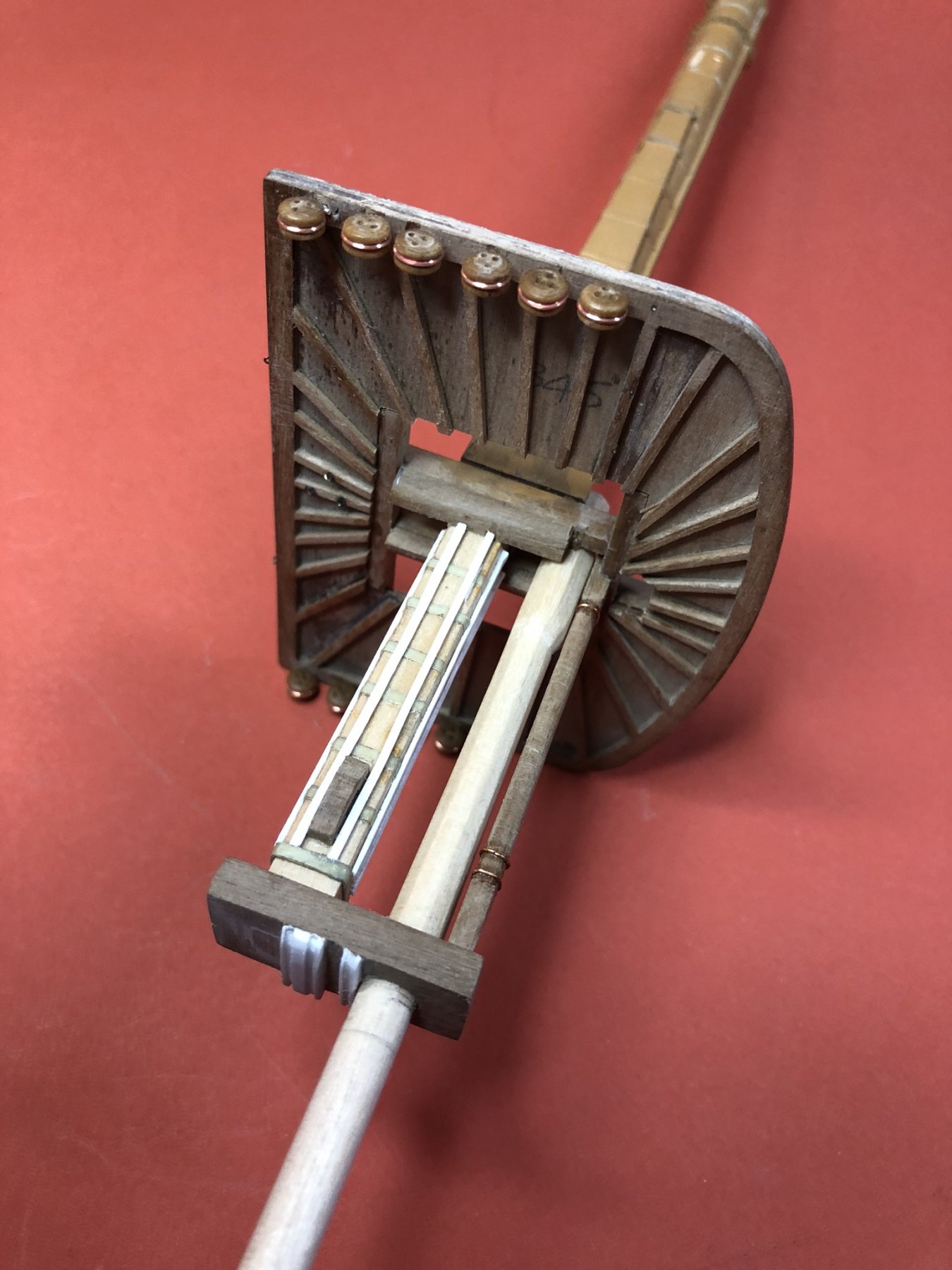
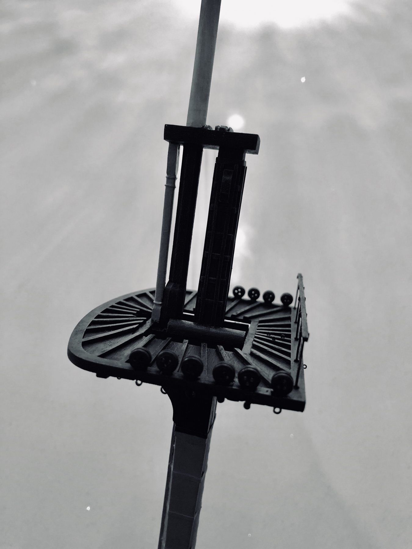
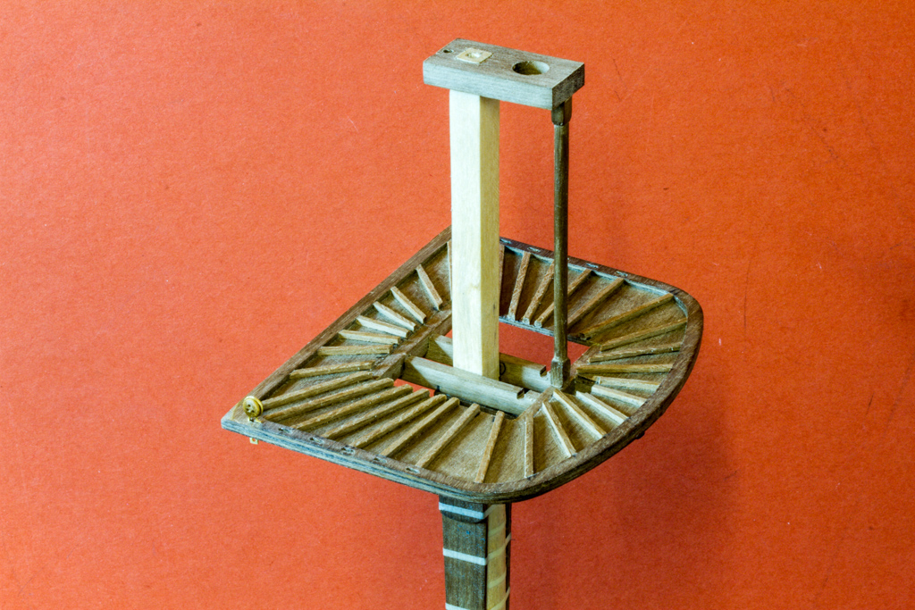
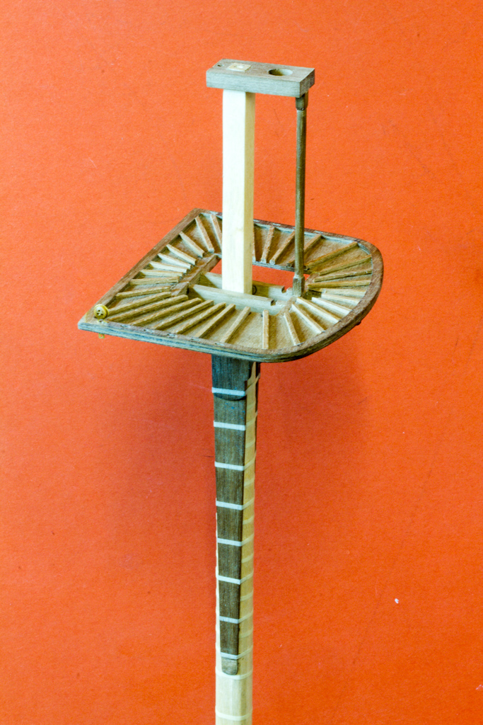
Hi all, Nearly time for masts and I didn't fancy my chances with a draw knife or David plane, so spent the weekend modifying my trusty lathe from the 'rough-but-functional' school of engineering - this was a scrap-heap challenge, so everything you see was lying round the workshop somewhere, so you could argue I built this for nothing. should be self explanatory from the pictures I hope:-
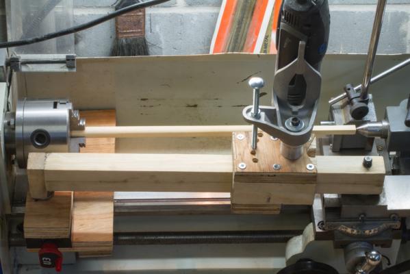
It's designed to cut any taper (as well as cylinder) within reason with the lathe running, or will taper individual faces and cut parallel square or octagonal sections with the indexing plate and the lathe stationary. In both cases the Dremel does all the work.

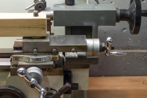
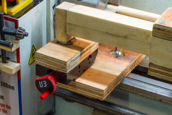
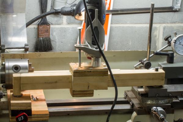
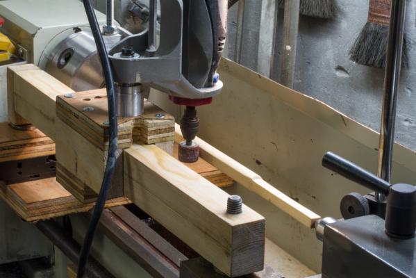
Strangely, it all seems to have worked!
Thanks for looking.
Nick
-
-
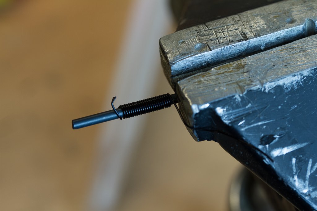
Yesterday I was mostly making anchors:-
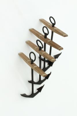
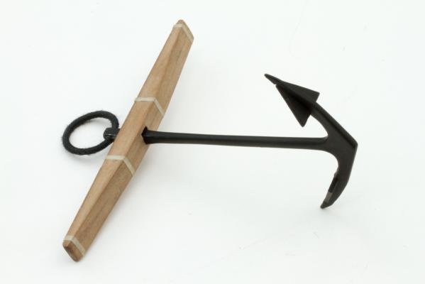
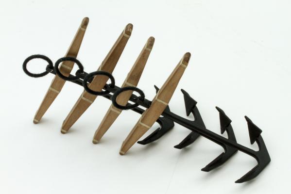
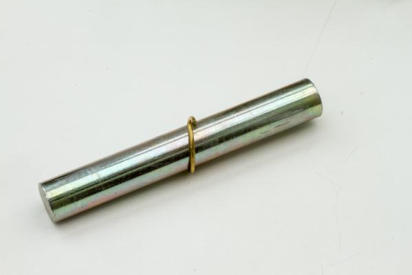
Good fun actually, I formed the rings by winding a 'spring' of 1.5mm brass wire around a 14mm dia steel former, this was under a lot of tension, so 'persuading' with heat was applied by blowtorch, it was then a case of slicing the spring into rings with a Dremel cutting wheel, forcing flat in the vice, inserting into the anchors and soldering closed.
Puddening was then applied to the rings with 0.5mm black thread.
The bands are just formed from my thinnest masking tape.
Thanks for looking.
Nick


HMS Victory by nickedw - Caldercraft - 1/72nd Scale - First wooden Ship build
in - Kit build logs for subjects built from 1751 - 1800
Posted · Edited by nickedw
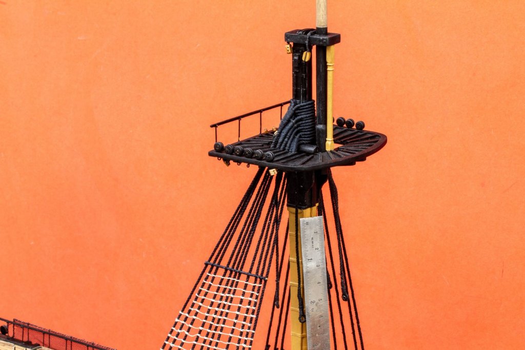
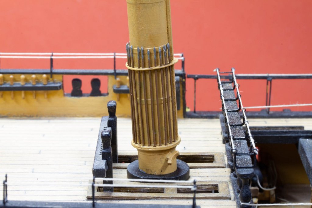
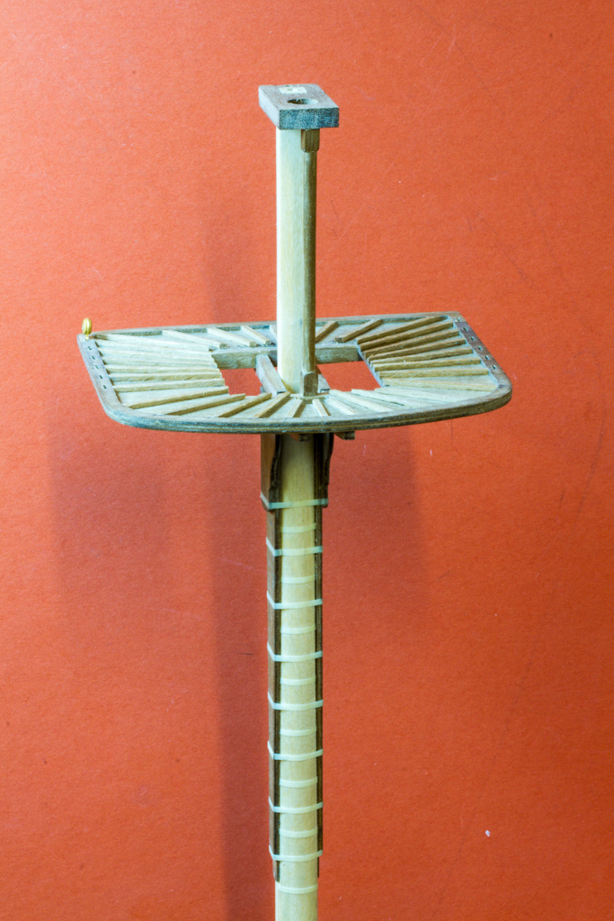
Fun with mice today.
I'm trying to produce a decent looking mouse for the next stage of my build, so I turned a wooden former on the lathe from scrap dowel
I then modified my server that I built a few weeks ago, by adding a couple of nylon gears I had in the parts bin, and then threading them with .25mm thread
I then carefully pulled them in to the base of the mouse taper, ensuring they were evenly distributed
After that it was just a question of darning a covering for the wooden mouse formed, here's how it turned out