Mark P
-
Posts
1,774 -
Joined
-
Last visited
Content Type
Profiles
Forums
Gallery
Events
Everything posted by Mark P
-
 Hi Archnav; The dimensions of the 'stop beam' in the excavation report bear little resemblance to anything quoted by Steel or Fincham. The excavator lists this timber as being 1.4m long x 160mm x 260mm at its widest (55" x 6 1/2" x 10"widest) This is a very substantial piece of wood. Its curved inner face is conjectured to have been designed to make traversing the gun easier. This cannot be any connection with anything referred to by Steel under the heading 'Port stops'. I can think of no obvious reason for the differences between Fincham and Steel, except perhaps for different yards working to different practices (or changing customs over time) The 3 1/2 " minimum may be a typo, or it may not. Can you post the relevant part of the text from Steel. I cannot find it in my (digital) copy. Separately, and rather worryingly, and referring to the 'Colossus' report: although the drawn sections show no sign of the waterway, the photographs do appear to show one! The side view of the standard (fig 30 in the report) quite clearly shows a shaped timber running along in the angle between the deck planks and the side planks. The bottom inner corner of the standard has been cut away to clear this and leave a gap, which was to allow water to flow through so that it could reach the scuppers. In addition, in the photos you have posted fig 28 shows this same length of timber, visible below your words 'slot has fallen apart'. By the way, what programme do you use to insert the pictures here. I tried, but it was beyond my skills. I need to educate myself! Concerning the piece of timber which presumably slotted into the small battens at the bottom half of the gunport, this may well have functioned to stop water entering when there was a bit of a sea running. But bearing in mind that the seamen messed at a board table set up with one end fixed into the gunport, it would also have served to prevent items on the table from sliding through the port if it was open, and making a quick descent into the depths. Two functions from one piece of wood. It would appear to be that the excavators have missed a piece of timber. Maybe, as the drawings were made on land, and possibly not by the person who was underwater, the illustrator may have had a pre-conceived idea of how the deck planks meet the sides of a ship like Colossus. All the best, Mark P
 -
Thank you Archnav for the link to the Colossus' wreck excavation reports. The stern carving has been mentioned on this site before (which was the first I knew of it) It has now been conserved (by the Mary Rose Trust) and is on display, at Tresco on the Scillies, I believe. However, the wreck excavation reports mentioned by Archnav are most interesting. I have not looked at them all, but the 2012 investigation and monitoring report deals in part with the excavation of a gunport. This is featured around page 32-38, and has some interesting items. The sections through this show the outer planking stopping short of the port cills, to leave a rebate. Of further interest is the presence of a standard knee in the excavated section. Another is reported from an earlier, adjacent, excavation, and the report concludes that they were present between each gun port. As these are not always shown on models, there has been some previous discussion as to whether or not these were still in use in the final decades of the 18th century. Their presence on a ship launched in 1787 shows that at that time they still were. Also of interest is the fact that the standard is made up of 3 separate pieces of timber. Many timber sizes are given, which is of interest also. Thanks again, Archnav. All the best, Mark P
-
Good Morning Gentlemen; Thank you all for a very illuminating thread, which I have followed with great interest. I believe that Archnav's original question has been answered by a combination of earlier replies, as shown below. First I quote part of a post by Wayne, which is part of a very informative extract he posted from one of John Fincham's works. Followed some time later by Archnav's posting of an extract from Brian Lavery's AOS book on Bellona. The description from Fincham, quoted by Wayne, seems to me to fit perfectly with the illustration included in Archnav's post showing the Bellona's ports. Taken together, the two are clear in their meaning. The port stops are formed by stopping the side planking slightly short of the actual port opening in the timbers, with the greatest width of exposed frame timber left at the bottom. This immediately creates a rebate, which will provide a good seal, and is easy to make. The rebate in the ship's side is thereby formed without any additional work being required to produce it. Likewise, the corresponding rebate in the lid is formed by the inner planking (lining) of the port lid being narrower than the outer layer of the lid's planking. Again, no need to perform any extra task to create a rebate. The ship's futtocks or toptimbers, and the port cills, are then left exposed to form the sides of the opening, and not covered in any way with any timber. The ship is planked; the port lid is made; and the two are put together when the lid is hung. Job done! At no part of the process is any extra planking fixed to the sides of the opening to form a stop. If this was to be done, it would open up a real can of worms: is the regulation size of the ports, listed in so many Naval documents, to be taken to refer to the port size before these additional timbers are fixed, or after? All the best, Mark P
-
Hi Mark; More lovely work. She's coming along beautifully. So interesting to watch. Regarding the relatively small size of the hooks, in full-size work an 8" thick oak post let into a horizontal timber by only 1" is remarkably resistant to lateral forces. The same effect would apply here. Keep up the impressive work. It looks a bit chilly outside! Stay indoors! All the best, Mark P
-
Good Evening Bear; Not sure if this is too late to be of any help to you, but as you are talking of a Royal Navy vessel, I would assume that models of other RN vessels would be a guide. I have seen quite a few now, out of their cases, and all those which had red-painted bulwarks had the cleats, kevels, stag-horns etc painted the same red as the bulwarks. All the best, Mark P
-
Hi Tom; It is my firm belief that a boom was in use earlier than 1790, as I have contracts for several 74 gun ships built well before this date, which specify a metal crutch on the quarter to hold the boom (presumably when lowered) I would therefore not dismiss the idea of a gaff and boom combined. There was also a major overhaul of rigging practice in the 1770s. I cannot remember exactly when, but maybe another member can be more specific. If your vessel's second refit occurred after this overhaul, I find it difficult to believe that a full-length mizen yard would be retained. All the best, Mark P
-
Hi John; Sorry, but this style is actually called 'hook and butt' planking. Anchor stock is similar, but doesn't have the hooks. All the best, Mark P
-
Hi everyone; Siggi, thanks for the pictures of Centurion, she's a lovely model, and the others. Everyone here is saying essentially the same, that the wale curves upwards towards the stem, as Siggi's excellent bows-on shots show. But when seen from some angles, it can appear to flatten out a bit. Siggi's shot of Balchen's Victory shows this just starting to happen. The point then is that, if the modeller notices the flattening, he must check his drawings and dimensions, but most importantly, he should not try to increase the upward curve of the wale to counteract what is an optical illusion. Not unless the measurements are wrong; hence Druxey's comments. The risk is that the upward curve will be increased beyond what it should be, when the eye tells us that the wale looks wrong, but it is actually correct. Mark, I wish I had the time to spend on my model that you do! I'm envious, in a good way! One note of caution regarding the 'Bellona' model, though. I think that the top strake of the wale is stopped short of the bow. There are only 3 strakes, and there should be 4. So I would be more inclined to follow the bottom curve than the top curve. All the best, Mark P
-
Hi Mark; I would be more inclined to make an inner surface template and band saw it to almost the right shape, with a fine-tooth blade, finishing by sanding. This would seem to be quicker. All the best, Mark P
-
Hi Mark; Thanks for the explanation. I must make one of these. All the best, Mark P
-
Hi Mark; That looks like an ingenious steamer. I have the exact same wall-paper stripper, and you've just given me an idea of what to do with it that the Admiral will probably want to keel-haul me for! Can you enlighten me as to the purpose of the holes in the side of the tube? I also agree with Druxey: very neat and well formed clamping arrangements. All the best, Mark P
-
Gun deck bulwark color
Mark P replied to DocBlake's topic in Building, Framing, Planking and plating a ships hull and deck
Hi Dave; The contemporary model of HMS Ajax in the Science Museum archive, which I have studied and photographed out of its case, has red bulwarks and black spirketting on its upper deck (the black spirketting is not as common as red, from what I have seen) This is then repeated on the lower deck, although it is much more difficult to see. The centre-line fittings on the lower deck are also painted red, as are the sides of all the deck beams to the upper deck and lower deck (and presumably their undersides, although none of my photographs show these) All the best, Mark P -
Hi Ron; You got it exactly right. That's the marine walk. All the best, Mark P
-
Greetings Ron; The marine walk is a tapered grating which runs from the top of the beakhead bulkhead forward onto the bowsprit. It was presumably to give a good vantage point for a marine sentry when in port, or for several marines in battle. HMS Victory has a good example. Look for pictures of her bows, and you will easily spot this. All the best, Mark P
-
Hi Tim/Steven; Further to earlier posts, I am reading Lavery's book 'Nelsons's Navy, Ships, Men & Organization', and he says that the ship's carpenter and his mates were responsible for making the mess tables and benches for the crew, and the tables and chairs for the gunroom and wardroom. As this would have been done using government supplied timber, there would certainly have been an official listing of what they were allowed to make. All the best, Mark P
-
Cathead Angles
Mark P replied to allanyed's topic in Building, Framing, Planking and plating a ships hull and deck
Hi Allan; My guess is that it is drawn this way to show the termination of the main rail clearly, as this is obscured by a normally drawn cat-head. Can't think of any other reason; and I've certainly never seen a cat-head this way on either a model or a draught. All the best, Mark P -
Beam Arms
Mark P replied to allanyed's topic in Building, Framing, Planking and plating a ships hull and deck
Hi Allan; Thanks for the info. I will see if I can get a look at this once the plans archive is accessible again (it's shut at the moment while the storage area is re-built) Concerning beam arms, nothing I have been able to find is any earlier than your draught. Everything from the Restoration era neither mentions nor shows beam arms. All the best, Mark P -
Hi Dafi & Druxey; Thank you for your thoughts. I was not aware that the ladders were changed when clearing for action. Was this a widespread thing, or limited to certain ladders on certain vessels? Druxey: I had to look up 'rubric'; that's a new one on me. I always thought it was something connected with religion! I've sent an email to the staff at 'Victory', asking about the means of access to the storerooms. I will pass on any reply I get. All the best, Mark P
-
Beam Arms
Mark P replied to allanyed's topic in Building, Framing, Planking and plating a ships hull and deck
Hi Allan; The draught you show looks like a good detailed one. Is this the Elizabeth, 1706, which you refer to? All the best. Mark P -
Good evening Druxey, Wayne; Thank you for your thoughts on this. I think that this paragraph served as a general 'catch-all' specification, which would cover anything that might have been missed in the main part of the contract. Some of the things listed here have already been described in their due place. It could indeed refer to the railing around the companionway, as these were certainly features of the deck furniture, and they could be said to 'encase' the stair; although I don't think I've ever seen the ladders called anything except ladders. I that it could well also relate to the means of accessing the store rooms. Does anyone have any knowledge of what is fitted in the 'Victory' for this? I've been to see her, but the storage rooms are not part of the general tour. On the red drawings for inboard works, the ladders into the magazine and aft powder room are normally shown. However, nothing is shown to give access into the store-rooms, which, even if they were not as deep as the hold, would still have been pretty far below the orlop, especially when empty. And a set of staples in the bulkhead would not take up a lot of room. I think that I will send an email to the people at the Victory, and see if they can shed any light on this. Isn't it Peter Goodwin who is in charge nowadays? All the best, Mark P
-
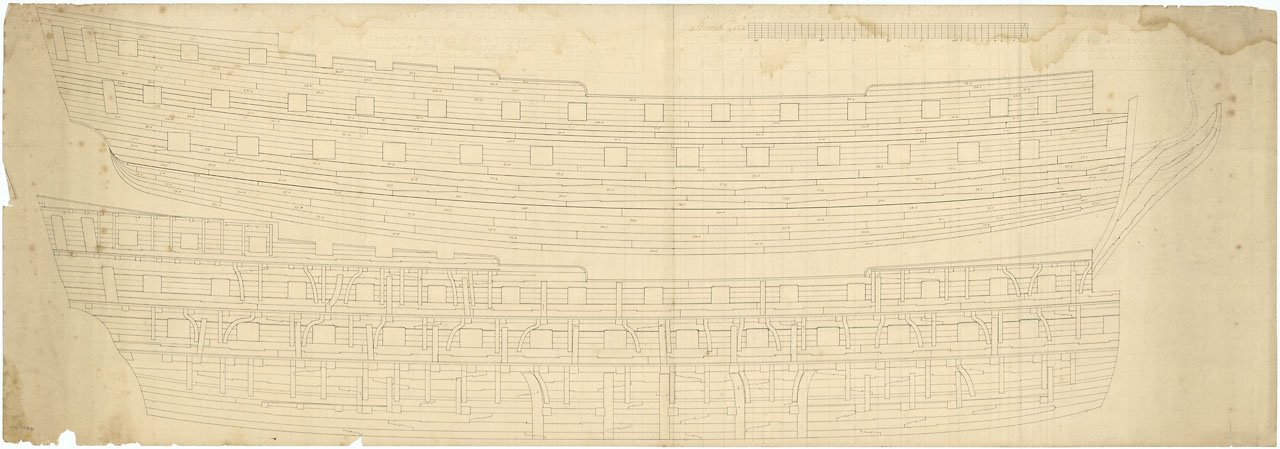
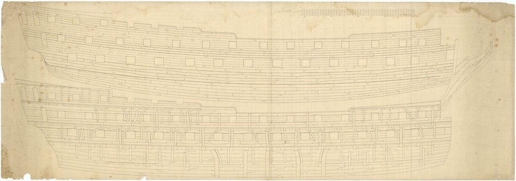
Hi Mark; You raise an interesting point regarding hanging knees. The Berwick was ordered in 1768. The Culloden contract, dated 1770, makes no mention of iron knees for either the gun-deck or upper deck knees. However, the Fortitude contract of 1778 makes several mentions of iron knees for deck beams, near the stern, & to as many of the other beams as may be done. This would make it unlikely that the knees shown in the drawing are of iron, unless it is from a later re-fit. The NMM catalogue entry states that the drawing is not dated, unfortunately, and so could be later than the build date. Unless there is something on the drawing which would indicate a date, we probably cannot be sure if the knees are iron or timber. One final thing: the NMM have/had a contract for building a ship which was listed as being that for 'Berwick', and which mentions iron knees. However, as the contract is quite specifically dated to 1779, with Mr Perry at Blackwall (on the Thames) it is most unlikely to refer to a ship which was launched four years previously at Portsmouth. This anomaly has either been recently corrected, or is about to be so. All the best, Mark P
-
Rigging lines located inside of shrouds?
Mark P replied to Mickgee's topic in Masting, rigging and sails
Hi Michael; Jim Lad is right. Many ropes for the running rigging lead through blocks under the top, then down the inside of the shrouds, often passing through a 'shroud truck', (I think it is called) which is a wooden tube lashed to the shrouds to contain the rope and give a fair lead to the belaying point. For top & topgallant sails, some of the ropes belay to a cleat which is lashed to the inside of a topmast shroud. All the best, Mark P -
Hi everyone; I have looked at the plan of the orlop for 'Tremendous', a 74 launched in 1784, and the scuttles are close to the bulkheads, which would allow access to a ladder fixed to the bulkhead. Bearing in mind that the depth in hold is 20 feet, they would certainly have needed a means of climbing down. The inboard works does not show any ladders here, so maybe the 'Iron Stair Case' does refer to a means of getting down into the storage rooms in the hold. All the best, Mark P
-
Hi everyone; Gary: thank you for the info regarding Berwick. I have found the drawing you refer to in the NMM collections, ref no is J2633, or ZAZ7846. This is a remarkable drawing: lots of lovely information! I will have to get a copy. Click on it and it comes up a bit larger, and clearer. The planks of the wale are not symmetrical. The contracts I mentioned above all ask for hook and butt planking for the spirketting and other locations. It's very interesting to see this draught showing it so clearly though. Again, thank you, Gary. All the best, Mark P
-
Hi Mark; The backwards hook is on one of the two photos you posted here a few days ago. On the bow view, between the 2nd & 3rd gunports from the bow, on the 3rd strake down. The hook is backwards/upside down, and the remainder of the plank next to it is actually parallel sided, or close to it. You might be right about the apprentice. It is also possible that the individual planks within a strake were of slightly varying lengths. As long as the butts were kept well apart in adjacent strakes, it would not seem sensible to cut off a few feet of perfectly serviceable timber just to create a uniform length. But I might be wrong. I hope Gary can find the number for his picture. If it shows the whole wale, that would be most interesting. Below is an extract from the contract specification for the 'Fortitude' a 74 of 1778. This was also used for the 'Bombay Castle' of 1779, the 'Culloden' of 1770, and the 'Bellerophon' of 1782. MAIN WALES: The Main Wales to be in breadth from upper edge to lower edge 4ft 4ins, and in thickness 8 ½ ins. To have one fair Seam in the Middle & the two lower & two upper Strakes to be lock’d into each other with Hook & Butt wrought of such lengths and the butts properly disposed so as to give the strongest Shift to the Ports & to each other. All the best, Mark P