Mark P
-
Posts
1,774 -
Joined
-
Last visited
Content Type
Profiles
Forums
Gallery
Events
Everything posted by Mark P
-
Thanks Greg, for the answer. I will give this a try with my next batch. All the best, Mark P
-
Good Evening Greg; Thanks for the advice, especially the 'what not to do' bits. Not sure if it's the picture, but the polished guns look a bit more bronze than black. Maybe just cleaning with a cloth leaves them blacker, perhaps. All the best, Mark P
-
 One interesting point: In 1695, the keel of a large ship is specified as to be in not more than 3 pieces. In 1755, the keel of an admittedly larger, but not double the size ship, is specified as to be in not more than 6 pieces. Tells us something about how the availability of large trees changed in the interim. All the best, Mark P
 -
Good Morning Allan; The contract for Burlington & Severn, 2no 50 gun ships to be built by Sir Henry Johnson at Blackwall, dated 1695, states as follows: Keeles to be of Elme (Not More than in Three Pieces) and to be fourteen Inches Square in the Midships with Scarphs Four Foot Four Inches Long at least and Each Scarph Tabled and laid with Tarr & Hair, to be well bolted with Six Bolts by an Inch Auger. False Keeles To be Three Inches thick of Elme laid with Tarr & Hair and well fastened with Treenails Spikes and Staples. No other timbers are so described, although the knee of the head is not described at all, so this contract cannot be used to know what happened with those joints. The contract for Swan of 1694 is similar: The Keele to be of Elme (not more than Three Peices) and to be Tenn Inches square in the Midships with Scarphs of Three foot Eight Inches long at least, Each Scarph Tabled and laid with Tarr and haire to be well Bolted with Five Bolts by Three Quarters of an Inch Auger. The False Keele to be Three Inches Thick of Elme laid with Tarr and haire and well fastned with Spikes and Treenayles. This does then describe the head of the ship, but makes no mention of tar or hair: To Build a Faire Head with a firm and Substantiall Knee & Cheekes, Railes, Traileboards, Beast, Bracketts, Kelson and Standarts, and to Finish the Same with Gratings and Stooles of Easement for the Saylors, with a Dead Block Carved for the Tack between the Railes, and with Mortices in the Knee for the Gammoning, and Washboards under the Cheekes. Other contracts of similar date are phrased in an almost identical manner. However, moving forward in time, the contract for Warspite of 1755 is more detailed: Keel. The keel to be Elm, not more than Six pieces, One foot Six ins square in the Midships, sided afore One foot two inches, and at the aft part of the Rabbit of the Post Eleven ins & a half; the Scarphs Four feet Six inches long, tabled one into the other, laid with white Flannel or Kersey, and Bolted with Eight bolts of One inch & an eighth diameter, the lips of the said Scarphs not to be left more in thickness than Five inches and a quarter. False Keel. To be in two thicknesses, the Upper one Four inches, the lower one three ins thick, so as to make the Main and False keel together one foot Nine ins below the Rabbit, not to have more than Six pieces of each, of proper lengths, to give Scarph to the Scarphs of the Main Keel and each other; to be laid with Tarr and hair, and Sufficiently fastened, the Upper one with Treenails, and the other with Nails and Staples. Stem. Not to be more than three pieces of good sound Oak, quite free from defects of any kind, sided at the Head (which is to be continued down to the upper side of the Upper Cheek) two feet, below the Hance One foot six ins, and at the Fore foot, the bigness of the keel; Moulded at the head One foot Six inches, and at the Forefoot the same as the keel, the Scarph Four feet long, tabled one into the other, laid with white Flannel or Kersey, and Bolted with Six bolts of One inch & an eighth Diameter, two of the middle Bolts to go through the false Stem and well chenched thereon; the Lips of the Scarphs not to be more than five ins and a quarter thick. The knee of the head is described thus (note the mention of Canvas, which, with tar, I have seen mentioned as a seal in various places, such as over the tops of the hawse pieces) Knee of the Head. To extend to the Upperside of the Upper Cheeks, to be One foot four inches thick at the Stem; the two Upper Bolts to be Two inches three eighths of an inch diameter in the Knee, and two inches and a quarter diameter in the Stem; the third two inches diameter in the knee, and one inch three quarters in the Stem; the fourth to be one inch seven eighths in the knee, and one inch Five eighths in the Stem; the Fifth to be One inch three quarters in the knee, and one inch Five eighths in the Stem, and all the rest to be but one inch & a half diameter. All the holes to be bored through with proper Sized Augers, that is to receive the Bolts in the least drift, that no Reaming may be suffered from the Stem in. That the holes be bored before the Canvas is put on, and the knee Swung off to Observe if the holes are all good, before any Bolts are drove; To have throat pieces of Sufficient depth of Elm, tabled and Billed, and well secured with Bolts drove up, with Pluggs. This would seem to indicate that a layer or layers of canvas, presumably tarred, was placed between the fore side of the stem and the corresponding face of the knee of the head. Moving forward approximately 30 years, the contract for Ganges of 1782 is surprisingly similar to that for Warspite: KEEL: The Keel to be Elm not more than 6 pieces if to be got, otherwise to have a short piece Abaft of about 22 feet, if required to be of Oak the foremost Piece about 24 ft, and the intermediate Pieces to be as near of a length as can be made suitable to the whole of what remains. To be 1ft 6 ins Square in the Midships, sided afore 1ft 2 ins, and at the Aft part of the Rabbet of the Post 1ft 0 ½ ins, The Scarphs to be 4ft 6ins long tabled one into the other laid with White Flannel or Kersey and Bolted with 8 Bolts of 1 ¼ Diamr, the lips of the said Scarphs not to be left more in thickness than 5 ¼ ins. FALSE KEEL: To be in one thickness of 7ins so as to make the main and false Keels together 1ft 10 ins below the Rabbit, to give Scarph to the Scarphs of the main Keel to be laid with Tar and Hair and sufficiently fastened with Nails & Staples. STEM: Not to be more than 3 pieces of good sound Oak, quite free from defects of any kind, to be thwartships at the head 2ft 2 ins and to diminish from thence to 1ft6ins at the lowerside of the lower cheek and at the end of the Keel or reconciling of the Sweep 1ft 2ins. To be moulded at the head1ft 6ins and at the fore foot the same as the Keel, the Scarphs 4ft long tabled one into the other, laid with white Flannel or Kersey, and bolted with 6 bolts of 1 1/8 Diamr. two of the middle Bolts to go through the false Stem and well clench’d thereon, the lips of the Scarphs not to be more than 5 ¼ ins thick. The Rabbit to be taken out agreeable to what is expressed in the Draught. The knee of the head is again described, again mentioning canvas: KNEE OF THE HEAD: The Knee of the Head to extend to the upperside of the upper Cheeks, to be 1ft 5ins thick at the Stem. The two upper Bolts to be 2 3/8 ins diar; in the Knee & 2 ¼ ins in the Stem. The third 2 1/8inches Diar; in the Knee & 2 ins in the Stem. The Fourth to be 1 7/8 in the Knee & 1 ¾ in the Stem. The fifth to be 1 ¾ in the Knee & 1 5/8 in the Stem, & all the rest to be but 1 ½ in diar; . All the Holes to be bored through with proper sized Augers that is to receive the Bolts in the least Drift. That no reeming may be suffered from the Stem inwards, that the holes be bored before the Canvas is put on, and the Knee swung off to observe if the holes are all good before any Bolts are drove. To have a throat piece of sufficient depth of Elm, tabled & billed, well secured with Bolts drove up with Plugs. In all cases only the timbers I have listed are described as having any sealing material within the joints. Sutherland may well have something to say on the matter, although Steel will be a bit late for your period. All the best, Mark P
-
Good Evening Jason; I'm afraid that I have not seen the Navy Board warrant ordering that the painting of names should cease, so the only reason I can give is as above, which I read somewhere in connection with this. 17th century ships did not have their names painted on them, nor their models, but they certainly appeared during the 18th century. As Druxey says, the Navy Board order that names should be painted on sterns was probably an official recognition of an established but unofficial practice. Thanks for the picture Druxey: that must have been a massive driver sail she carried. I wouldn't want to sew that by hand! All the best, Mark
-
Thank you Allan & Mic-art; One caveat: As-built draughts well into the 1780s show the ships with their names displayed on their stern. A lot of marine artists show the names also. It is possible that the Navy Board's directive to cease the practice was somewhat ignored, which would not be too unusual
-
Good Evening Allan; Druxey is almost correct. I think it was 1771, not 1781 when it commenced. I don't have the warrant when names were first mandated, but this is the wording of the warrant issued by the Navy Board in 1772, changing the rules: 9th September 1772 Notwithstanding our Warrant of 28th June 1771 These are to direct and require you to paint the Name of the Ships at your Port in Letters as large as the second Counter will admit, as they come in course of painting without any compartments [painted border] round them Dated the 9th September 1772 To the respective Officers of all the Yards. This practice lasted for about 10 years, after which it was discontinued, as it was felt that this could give important information to an enemy. 1781-2 is probably when it was ordered to stop. All the best, Mark P
-
Thanks Allan; I'm sure you'll enjoy it and learn also. All the best, Mark
-
Frank Fox is well-known for his work on Charles II's Battlefleet, published many years ago, by Conway in 1980. Copies of this command good prices on the second-hand market. His account of the Four Days Battle in 1666 is the best re-telling of a Naval encounter which I have ever read, and reveals an astounding knowledge allied with what must have been years worth of research in archives in Western Europe. It is far more than a bare narrative of events and their consequences. The historical setting, the Navy, the ships, officers, crews and customs, of the English and Dutch are all well described, which is what one would expect of any decent book. What sets this apart is firstly its readability, with no feeling of tedium or excessive quoting of statistics at any point; secondly the really clear and interesting explanation of just how much influence the shoals, tides & currents of the Thames Estuary and North Sea had on events; and thirdly the amount of clarity which is given to the abilities, shortcomings, characters, desires and motives of the various commanders and captains. The development of Naval tactics during the period (when the line of battle was first brought into use by the English fleet) is very well set out, with the contrasting tactical methods of the protagonists clearly explained and thoroughly analysed. The battle of Lowestoft the year before, and the St James' Day battle later in 1666 are recounted and their places and consequences in the Second Dutch War made clear. The decisive part in the year's events played by the French fleet, which never fired a shot in anger, and hardly saw an enemy ship at all, is analysed thoroughly. It was the perceived threat of Louis XIV's fleet which caused a large number of the Navy's best ships to be detached from the main fleet, leaving the remainder vulnerable. This was a mistake of catastrophic magnitude, made much worse by faulty intelligence and lack of scouting ships to report events. This meant, among other things, that the English commander was unaware that the Dutch fleet had sailed, for a week after it had set forth. This book will bring to its reader a deep understanding of the factors influencing Naval Battles in the Restoration period. I feel as though I have been thoroughly educated from reading this, but also, thoroughly entertained. All the best, Mark P
-
Good Morning All; The best method I ever used for making mast hoops was with an ordinary hand plane. This was to set the blade to a slightly coarse cut, and then carefully plane a long shaving off the edge of a plank of pine (no knots being present) The shaving will have a natural tendency to curl. Weight it down flat and coat the inner side with glue, then roll it around a suitable sized dowel, with a rubber band around the outside, and leave to dry. Once dry, this will give a perfect tube, from which hoops of the desired height can be cut with ease. This works for woldings and hoops for sails sliding up and down the masts. This was a tip I saw long ago in (I think it was) Underhill's 'Leon' book. But it works wonderfully well, and is quick. The plane needs to be sharp, of course. All the best, Mark
- 15 replies
-
- 12
-

-
Hi Hamilton; I have seen models with the lines worked from the tops tied off to the topmast shrouds just above the dead-eyes, and to the rail at the aft side of the top. I have also seen illustrations of them belayed to shroud cleats, but I cannot remember where I saw such illustrations. All the best, Mark
-
Good Evening Everyone; It must be remembered that clipper ships were a special case: captains drove their crews and their ships hard, and nobody got to be captain of a clipper without thoroughly knowing the ways of a sailing ship, so they had a good idea of where the boundaries were. The main point was that the first ship back was guaranteed a large premium on the price of its cargo, and the captain stood to get a bonus. Risks were taken in pursuit of this which doubtless most captains and crews would have deemed foolhardy. The reference to the Americas Cup is a good one, for it was a race: first back to port scoops all the prizes. All the best, Mark P
-
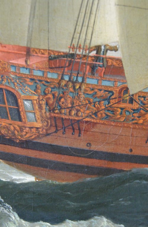
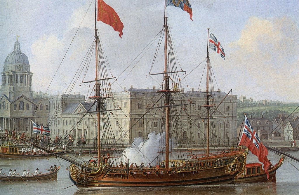
Good Morning Hamilton; Be very wary of using a kit as a precedent, for the reasons you give. The paintings of Royal Caroline shows pin racks on the shrouds, and fairleads lashed to the shrouds above them. See below two extracts from paintings, although one has no fairleads, and the other has no racks on the mizen shrouds. I think that this can be ignored as artistic licence. The painter of both pictures, John Cleveley the Elder, knew the ship very well, having worked on painted scenes in her State Apartments during her fitting out, and being previously a shipwright at Deptford Dockyard where she was built. One other interesting point: I have just finished transcribing the contract for 'Edgar', a 70 gun ship built by Francis Baylie in 1668-9. This specifically mentions fitting for rigging, being listed as 'Kevells, Ranges, Cleates, Turnpinns and whatever shalbe requisite for belaying the rigging'. Turnpinns I can only believe to refer to belaying pins. I have not seen this word before in all the other contracts I have transcribed, but I cannot think of it meaning anything else. All the best, Mark P
-
Good Morning Jason; Regarding the AOTS volume, David White was/is a very knowledgeable person, and if he says that there were separate ringbolts, I would tend to take his word for it. My only qualification on this matter is that I do not remember ever seeing any such ring/eye bolts in either models or books. However, as has been said before, absence of evidence is not evidence of absence. Concerning duality of function, it is very unlikely that train tackles would need to be rigged at the same time as the ship was anchored. This is only likely in a defensive posture in face of superior force, which was rare. So the same ring/eye bolt could perform different functions as required. Having said that, you are quite correct that Lever's stoppers do look pretty permanent. My best advice would be to do as you think best, but with the balance of probability being as per David White's volume if you are building a model from the late 18th century or after. All the best, Mark
-
Mast Partners in ships of the line
Mark P replied to michaelpsutton2's topic in Masting, rigging and sails
Morning Druxey; I would have agreed with you on this until Michael asked the question. Before posting an answer, I did a bit of checking, and according to Marquardt the situation is as in my previous post. Perhaps he is wrong, or perhaps he is right, and it was done so on three-deckers because the deck beams on the middle deck were more substantial than those on the upper deck. Some further research is perhaps indicated. All the best, Mark -
Good Morning Mark; With regard to port stops, Druxey & I, and others, have had some lengthy discussions on the subject, which I feel fairly confident in saying settled the matter to the satisfaction of most, which was that no additional timbers were added to the sides/tops/bottoms of ports, and that the stops were formed by ending the planking short of the sides of the openings. Perhaps Druxey can point you to these posts should you wish. It is beyond my skill level, unfortunately. All the best, Mark P
-
Good Evening Hamilton; Druxey is quite correct in what he says, and a good example of pin racks is shown in John Cleveley's paintings of Royal Caroline. The earliest I know of, dated to 1750, shows pin racks on all the shrouds. A model of the 74 gun Ajax, an early example of the type (1767) has single belaying pins in the rails in several places. All the best, Mark P
-
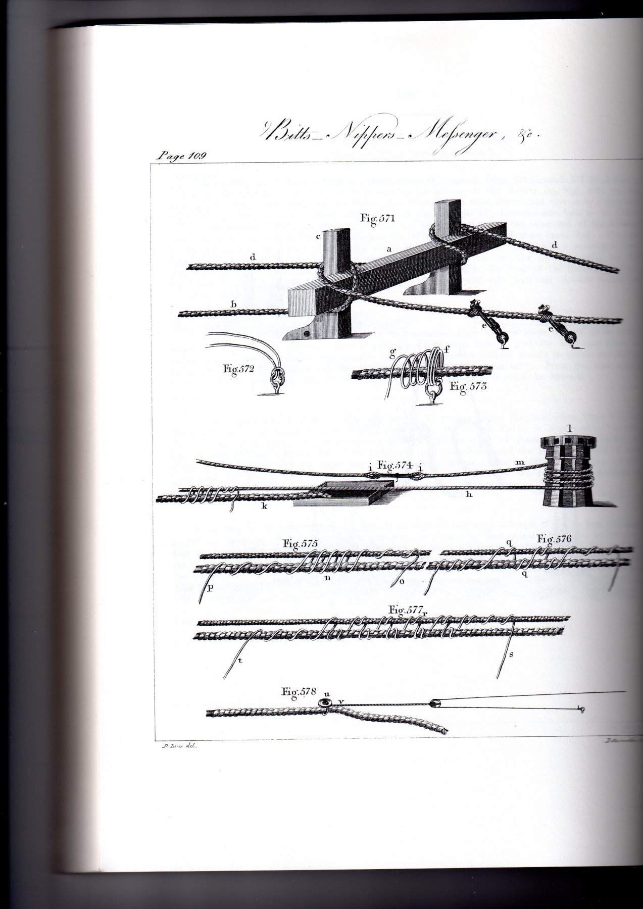
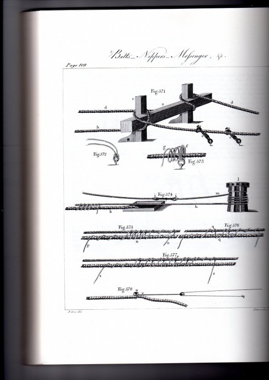
Good Morning All; I can understand Mac's thinking, but there is no need to get slack in the cable. The procedure was to make the inboard end of the cable fast to the bitts before the anchor was let go. The anchor would then hit the bottom, and the ship would be allowed to fall off until brought up by the cable becoming taut. Standard practice was for the cable used to be be three times the depth of water in length. That the cable was given a half-turn around the top of the bitt pin and then a similar turn, in the opposite direction, around the end of the cross-piece is shown in various contemporary illustrations. The cross piece for a third-rate 74 was around 18" square. The anchor cable for a third-rate was around 7" in diameter. For a first-rate it was between 7" & 8" in diameter, and in 1745 a ship of this rate would have carried 9 different cables of varying lengths for its largest anchors. A third-rate, along with most other rates, carried 7 cables, most of them about 100 fathoms (600 feet) long. They could be joined to allow anchoring in water over 200 feet deep. Mac is right to mention the expense. The Royal Navy, and presumably other Navies, placed a high value on anchors and cables, which were very expensive. There are regular mentions in the archives of dockyard personnel, or crew members, selling the cut-off ends of cables. When caught, they would be severely punished. It is hard not to feel sympathy for some of them, though, a common (and very true) defence being that they had not been paid for two or three years, and their wife and children were starving. A consequence of this high value was that anyone who salvaged an anchor, or anchor and cable, was well-rewarded. The Navy would sometimes commission a non-Navy vessel to go and sweep an area where a ship or ships were known to have left anchors and cables. Below is a page from Darcy Lever's 'Young Sea-Officer's Sheet Anchor' (from Dover Books) showing the bitts, cable and stoppers (the cable is shown much thinner than in reality, and the knees to the bitts are much too short in both length and height) Note that the stoppers are used on the aft side of the bitts. All the best, Mark P
-
Mast Partners in ships of the line
Mark P replied to michaelpsutton2's topic in Masting, rigging and sails
Hi Michael; On an English 2 decker, the widest diameter of the masts was at the upper deck. On a 3 decker, this was on the middle deck. In all cases, partners were fitted on each deck, although presumably the masts were set up using the partners at the widest diameter for the initial wedging. All the best, Mark -
Good Morning Mark; One thing to keep in mind with planking is that where a continuation of the plank above a gun port would leave only a thin sliver of the next-below strake running over the gun-port, the plank above would often be widened in the vicinity of the port, so that it extended downwards and occupied the position of the below strake. The technical term for this was 'to give wood to the ports', which is frequently mentioned in building contracts. Whilst I have seen planking expansions showing this, I cannot at present remember where I saw one to include here for you. It was done by drawing a line at 45 degrees upward and outward from the top corners of the port, until this line intersected the lower side of the strake above the port. The area thus delineated was included as part of that strake. Also, as Druxey mentions, butts above or below gun-ports were specifically avoided. All the best, Mark P
-
Good Evening all; Ring bolts were provided behind each gun in the deck, usually set into either a deck beam (the structure of English warships was that a gun-deck beam was always sited directly below the centre of each port) although 17th century ships had a longitudinal carling close to the centre line each side, and the ring-bolt was set into this, at its junction with the deck beam, presumably passing through both. The train tackle was not used to run in the gun during battle (although it presumably was during some types of gun exercises) as the recoil of the gun would bring the gun back inboard as far as the breeching would allow. The train tackle was used to prevent the gun running back out during re-loading. In the earlier periods, guns were only issued with two tackles, and it was presumably necessary to un-hitch one of the two gun-tackles to use behind the gun for a train-tackle. Concerning stoppers, I believe that there might be some confusion with 'nippers'. The ship's anchor cable, being very large diameter and stiff as a result, was not passed around the capstan. Instead an endless loop of rope was passed around the capstan, similar to the way of connecting the ship's wheel, but with the other end passing through a large block in the bows (17th century practice was a little different, but followed the same principle) and this moving rope was temporarily tied or 'nipped' to the main anchor cable with short lengths of rope to enable the movement of the rope to be transmitted to the cable. As the rope came close to the capstan, the nippers were untied, and taken back to the bows to repeat the operation. This was normally an operation carried out by the ship's boys, hence a common term for boys being 'nipper'. Stoppers were used once the anchor had been 'let go', and was on the sea bed. The main strain of the anchor cable was taken by passing it once around the end of the riding bitts. However, as it was not unknown for bitts to break under the repeated straining of a ship riding at anchor in rough weather, stoppers were used as a back-up and to take some of the strain. In the sailing navy these were short lengths of rope made fast to ring-bolts in the deck, and lashed to the anchor cable. Normally three or four were used for each cable. These were left in place until it was time to raise the anchor. I have not seen additional ring-bolts fitted for stoppers, and the train tackles were only rigged when the guns were in use, so there would seem to be no problem with a ring-bolt serving a dual purpose. All the best, Mark P
-
Evening Bob; Speaking of 'Rabbets' vs 'Rabbits', and other terminology, the keel you show is actually the main keel, not the false keel. The false keel is a thinner strip fixed to the underside of the keel, designed to break away in the event of the ship grounding accidentally, thereby avoiding excessive stresses being transferred to the main structure, and giving the vessel more chance of sailing free. This false keel is shown in Alan's post above (no 4) showing a ship's keel. I am not aware of longboats ever being fitted with a false keel. It is fair to say though, re 'rabbits', that the word is frequently spelt this way in contemporary contracts describing ship-building. The only version I have never seen amongst the many spellings, is the modern word 'rebate'. All the best, Mark P
-
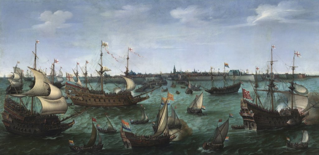
Hi Tom; I would be very careful before giving too much credence to anybody who talks of Navy ships from the early 1600s being 'HMS'. This was a term which came into use much later. In the 17th century ships were always known as 'The' whatever. So Mayflower was called 'The Mayflower'. Prestige ships, or 'Ships Royall', were certainly painted beautifully, and gilded. Check out the painting of the 'Arrival of the Elector Palatine at Flushing' and other similar ones, which will give a good idea of what was normal for some ships in those times (the Elector had just married King James I's daughter, sister of Charles I, and returned to Europe in the King's best ships) It is probable that any captain with any self-respect would try to do his best for his vessel, but Louie's comments in post no 4 above are certainly worth keeping in mind also. At the end of the day, nobody knows, so do as you wish! All the best, Mark P
-
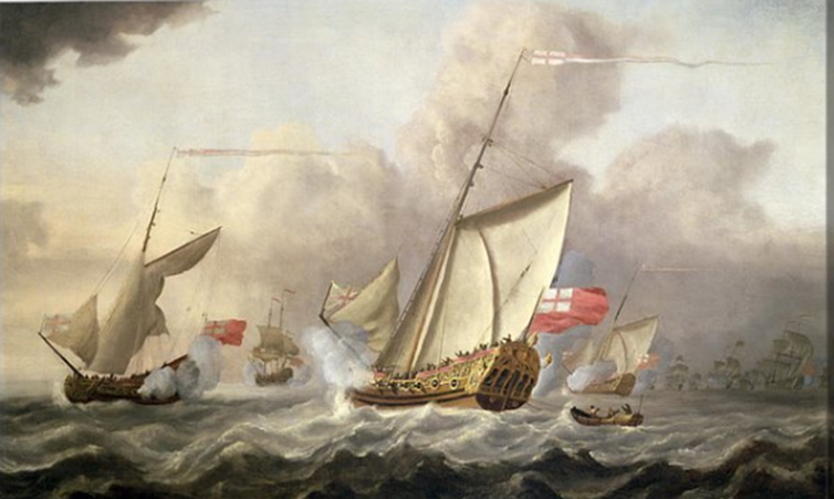
Good Morning Gregory; If your model is 17th century (the name was used over many decades in the 17th & 18th centuries) and you want to know about 17th century yachts, search the internet under 'Van de Velde yachts'. The most prolific marine artists of the time, they were a father and son, appointed official sea artists to Charles II. Alternatively, search under the yacht Mary. Either way, you will see a wealth of illustrations in colour, which will almost certainly answer your question. On the above version of the Mary, the vangs seem to be single each side, and rigged with a tackle. All the best, Mark P
-
Hi RPaul; Record tools, based in Sheffield, was (I don't know what they are now) one of the premier English tool companies, who made a range of woodworking tools regarded as the finest by many craftsmen, who paid significant amounts of money to purchase a Record plane or vice. Who owns the company now, or where their products are made, I don't know either. A search on the internet will show something, I would think. I believe that they have links with Irwin Tools, which is also marketed as a reputable brand (they are expensive, certainly) I once had a Record Power bandsaw, which certainly did all I wanted it to do, and performed well for several years. I sold it when I had to downsize, so I no longer have it; a matter of not infrequent regret. All the best, Mark P