Mark P
-
Posts
1,774 -
Joined
-
Last visited
Content Type
Profiles
Forums
Gallery
Events
Everything posted by Mark P
-
 It's amazing what skill and patience can do, starting with what is obviously a well-designed and made pile of sheets of cardboard. Very well done indeed. An inspiring example. Taken together with Doris's wonderful card ship models, it is a continuing amazement what 3D masterpieces can be produced with a raw material which is, essentially, only two-dimensional. Great work Dan!
 -
Ship's name on transom
Mark P replied to JamesBhm's topic in Building, Framing, Planking and plating a ships hull and deck
Good Evening James; On the 9th September 1772, the Navy Board issued a warrant to all dockyards, instructing them to paint the names of ships on the second counter. The letters to be as high as can be fitted. No colour is specified. The only other comment is that the name is not to be in a 'compartment', meaning not in a painted frame. I do not know if this applied to cutters, but they are not excluded. Then, on the 25th June 1787, the Board ordered that the name was to be painted on a board in 12 ins letters, the board to be hooked (presumably fastened) to the second counter. However, the painting of names was cancelled after a relatively short period, not much more than 20 years at the most, I think. It was then stopped, as it was considered that it was information which might be useful to enemies. All the best, Mark P -
Good Evening gentlemen; Depending upon how far you want to go, there is one further thing to consider about hammock nettings: once the hammocks had been stowed they were actually covered with painted canvas to keep the sea-water off them (damp hammocks would not be much fun to lie in) I don't know if there was any particular colour used for this, but from memory paintings normally show a light-colour. All the best, Mark P
-
Admiralty model query
Mark P replied to iMack's topic in Building, Framing, Planking and plating a ships hull and deck
Good Morning Bob; That sounds like a valuable resource for anyone with an interest in 19th century ships. As you say, we are perhaps a bit 'wonkish', but to judge by the number of members on this website, we are all together a good-sized community. Thank you for the mention of the book on lofting. I have modern versions of several old volumes on this subject, but I will get hold of a copy of Alan Vaitses' book, as it might help to fill in some gaps. This is a new one to me, as I have never heard of it before, despite numerous searches on the Internet. All the best, Mark P -
Admiralty model query
Mark P replied to iMack's topic in Building, Framing, Planking and plating a ships hull and deck
Good Morning Greg; This is an interesting debate. I am afraid that I would not agree with you that the method as described by Simon Stevens echos Bob's comments. Bob mentions that not bending the timbers, and cutting them from straight timber would produce timbers with end grain in them, which is not desirable. If I understand Bob's posts correctly, we are both, as far as models go, attempting to describe a process where the desired result is a curved timber with no end grain. If Simon is correct, and he has undoubtedly seen far more ship models than almost anyone else, then there will be a lot of end grain visible in the frames of the models. I assume that Simon is describing the frames correctly, and that end-grain exists, and is merely difficult to see in the many published close-up photographs. My main point, however, is not the construction methods of the models themselves, but the extent to which the finished appearance of the models resembles full-size practice. Simon's description as quoted above does not discuss this, as he is describing only the method by which this appearance was achieved in the models. See below an extract from a contract from 1649, which was for 'Foresight', built by Jonas Shish at Deptford: This describes the floor timbers, and then specifies that the Navill timbers (lower futtocks) are to fill the room, that is to fit between the floor timbers. Then the next tier of futtocks is described, again with the proviso that they must also fill the room. This is a description of a ship built with a succession of interlocking, overlapping timbers, exactly as the Navy Board models appear. The six foot scarph describes the minimum extent of the overlap of the adjacent, side-by-side timbers. It is not referring to the later method of joining timbers. Auger Bolt fastening the same together, The space of Tymber and Roome, to be Two foote & Two ynches at ye most, The floor tymbers of the Shipp to bee Fourteene ynches up & downe, upon the Keele, and Eleven ynches in & out at the Wrong heads Att ye Bearynge & ten Afore & abaft, The Navill tymbers to fill the Roome, and to have Six foote Skarfe, The Tymbers upwards at the Gunndeck to bee Eight ynches in & out, & to have the like Skarfe, and the Roomes to bee filled with Tymber, To have a Substansiall Kelson, Fourteene ynches up & downe, and Sixteene The actual construction of the models is secondary to the main theme I am writing about. Which is that the appearance of the models is much closer to real, early to mid 1600s construction techniques than most people, more accustomed to later, much better documented, methods of ship-building, are aware. All the best, Mark P -
Admiralty model query
Mark P replied to iMack's topic in Building, Framing, Planking and plating a ships hull and deck
Good Evening Bob; Your point that you were referring to models when talking of battens is fair enough, and I am happy to stand corrected on that. Thank you for posting the pictures, which are always so lovely to see. As to whether or not the timbers of the frames for these models are bent to shape or cut from naturally curved timber, it is impossible to say, as the end results are visually identical. However one wishes to make a model's frames, naturally curved timber would be best, but is obviously not easy to get. The Boston model is, I believe, although I am not certain, the Royal William. The damaged model is either late 17th or very early 18th century. The Bonaventure is dated on its stern 1682 (not 83, if that is what the NMM has listed) and the Mordaunt, originally built as a privateer, I think, is of similar age. All of which leads on to the following: What is perhaps not realised by those more familiar with later building techniques is just how close to full-size 17th century practice the framing of such models is. Although it is generally stylised, especially as regards to the deadwood, and the length of the lower futtocks. Nonetheless, the use of interlocking floors, futtocks, navel timbers, and toptimbers was similar to that shown on the models. In the early and mid 17th century, few ships had more than 2 futtocks, and all contracts state quite specifically that the lower futtocks should fill the room, that is, they should fit tightly between the floor timbers. Although the use of paired frames and filling frames came into use well within the period in which such models were made, the models continued to be made representative of earlier practice for many years. The Peregrine galley, built at the turn of the century, was constructed with lower futtocks which stopped 2 to 3 feet short of the keel (this was reported when she was repaired in 1750) If the futtocks only overlap, and are attached to, one floor, as is sometimes shown in reconstructions in books on this subject, this is a much weaker form of construction than if the overlaps of the floors and futtocks form a continuous solid band of timber, such as the models show, and as full sized practice was. So to conclude, the models are a fair approximation to full-size methods during a large part of the 17th century. This has been discussed very well by John Franklin in his excellent book on Navy Board ship models, and by others since then. The sided thickness of the timbers used was also a reflection of full-sized dimensions, and was rarely, if ever, arbitrary. All the best, Mark -
Admiralty model query
Mark P replied to iMack's topic in Building, Framing, Planking and plating a ships hull and deck
Evening Roger; Thank you for your thoughts. I agree that it is important to be clear, when talking of ship-building in general, which Navy one is referring to. I would normally add 'Royal' to the word Navy, certainly, and have done in other posts. However, in this case the subject under discussion is Admiralty Board models, which are by definition already associated with the Royal Navy, without any need for further clarification. All the best, Mark P -
Admiralty model query
Mark P replied to iMack's topic in Building, Framing, Planking and plating a ships hull and deck
Good Morning All; The original query was about, and only about, Admiralty Board Models. As these ceased to be made around 1750, the only points to consider are either the construction of the models themselves, or full-size practice during the period when the models were prevalent. To make reference to much later (and much different) practice, or 19th century merchant vessels, is of no relevance to the subject of the original post, however accurately and thoroughly such practices may be discussed. Ships for the Navy were built from draughts from at least the reign of James I, originally using a system of 'whole-moulding'. This was used to develop frame templates at all stations where required. Deane's doctrine of Naval Architecture, and The Keltridge draughts, both from the 1670-80s show either most or all stations. A treatise on ship-building dating from the 1620s gives detailed and complex instructions on how to construct frames at every station, using a combination of geometry and mathematics. To advocate that Naval ship construction was carried out in any way otherwise, without use of a properly-drawn body plan or frame templates, can only be based on an (admitted) lack of knowledge. Whilst battens can be stretched between a few principal points to provide a hull shape, the degree of flexibility and lack of certainty which can be introduced by this method, especially in areas where a hollow is required, meant that it was both unsuitable and unused in Naval construction, except perhaps for very small vessels. Recent works by authors who have made a close study of Admiralty/Navy Board models shows that the construction of the frames closely replicates full-size practice of room and space. Grant Walker's excellent volume on third rates in the Annapolis Naval Academy collection is a good example of this. All the best, Mark P -
Admiralty model query
Mark P replied to iMack's topic in Building, Framing, Planking and plating a ships hull and deck
Good Morning All; I don't know if iMack, who started this thread will see this, but to go back to his original query: The number of frames/ribs in an Admiralty Board Model is equal to the number of station lines used to set out the ship's body. Each station line represents the fore face of the frames heading aft, and the aft face of the frames heading forwards. Note, however, that draughts normally show only every third station line. The number of station lines was dependent upon the size of the floor timbers to be used to build the ship, as it was this dimension which produced the 'room and space' measurement, which was the distance from face to face of successive frames. An important point to understand here is that in Georgian times the room and space was calculated slightly differently to that of the 17th century, when Admiralty (also commonly called Navy Board Models) started to appear. For models built in the Admiralty/Navy Board style, the distance between the ribs/frames of the model was normally equal to 17th century full-size practice. In those times, the space between the floor timbers was completely filled by the bottom of the first futtock, with the futtock stopping short of the keel. So to decide the number of station lines, it is necessary to know the room and space. See below an extract from a builder's contract from 1652, giving the room and space as 28". As the floor timbers are 14", the lower ends of the futtocks would also have been 14" to fill the space between the floor timbers. the keele with an ynch and quarter Bolt, the Flowre Tymbers to bee in length two and twenty foote, upp and Downe one foote, fore and aft fourteen inches, roome and Space to bee two foot four ynches, The Dead Rysing to bee four ynches at least; the lower Futtocks to fill the roome, and to have Six or seaven foote Scarffe in the Midshipps, the other Teere of Futtocks to have six Therefore, a model built to this room and space would have a frame every 28". Room and space varied according to the ship size. From early in the 18th century framing methods changed. Amongst other changes, the first futtock now reached the keel. A small gap, around 2", was left between the face of the futtock and the face of the floor timber of the next station. However, to construct a Navy Board style framed model, the futtock would need to be increased slightly in its sided dimension, to completely fill the space between the floor timbers. Again it is necessary to know the room and space. See below an extract from a builder's contract for 'Warspite' dated 1755. Room and space is 29" (very similar to that of 100 years earlier!) As the floor timbers are 15", the lower ends of the futtocks would be 14" to fill the space between the floor timbers (to build a Navy Board style model, the timbers could all be 14 1/2") Room & Space of Timbers. To be Two feet five inches. Floor Timbers. The Floor Timbers between Timber three, & Timber C, in the bearing of the Ship, to be Sided one foot three inches, and from 3 to 15 Aft, and from C to H forward to be sided one foot two ins; from 15 Aft, & from H forward, to be Sided one foot one inch; to be in length in Midships twenty five feet, eight inches, and afore and abaft as the draught directs. If you have a draught which shows station lines, the room and space is easy to find: the draught will normally show every third station line, so to find the room and space, and the number of frames you will need, divide the distance between the station lines into 3 equal portions. To find the shape of the intervening station lines, it will be necessary, as discussed in previous answers to this post, to loft them from the draught. All the best, Mark P -
Good Evening Kevin; In the eighteenth century dry dock facilities for 1st rates existed at most dockyards. As they did in the 17th century, in fact. Many first rates were built in dry docks, and floated out to launch them, rather than launching then stern-first from a slipway, as was normal for smaller vessels. Nelson's 'Victory', completed in 1765, was built in a dry dock at Chatham, and floated out (after a bit of panic when it was realised only a few hours previously that the dock gate was a little too narrow for her. If you search the NMM website under ship models, there is a very nice model of her as built, but sitting on a slipway, so wrong in that respect, but it will give you some idea of what a dock looked like. The ship herself looks far more attractive than the 1805 version, also. Well worth a look. All the best, Mark P
-
Evening all: By a coincidence, I recently bought a copy of this through 'Bookfinder', a site recommended by another contributor on this forum. The book is very detailed, and will teach almost any reader a lot they did not know previously. The reconstruction is based on the Stockholm model and on an anonymous treatise on shipbuilding dated around 1620, which is again very detailed, and gives a step-by-step guide to constructing a draught of a ship (although it contains some errors in the mathematics used, corrected in this book) I highly recommend this book to anyone with an interest in ships of this period, or with a general interest in their history or construction. All the best, Mark P
-
Good Evening Steven; Until some time in the early 19th century, sails were bent to the yard, as outlined above, by robands, believed to be a shortened form of 'rope-bands'. These were certainly in use in the 16th century, and presumably earlier. In the 19th century, the robands were no longer wrapped around the yards, but instead were made fast to jack-stays, a metal rod running the full length of the yard, fixed to it at intervals by brackets driven into the timber. Another feature of a yard, rarely shown on rigged models, were gaskets. This was a longer length of rope, normally looped and tied into a hank, which was used when the sail was furled up to the yard. The gasket was passed around the gathered bundle of canvas, and the yard, and made fast. The gaskets are the narrow points on furled sails, which cause them to hang in a series of swags from the yard. All the best, Mark P
-
Good Evening All; I don't know the exact details without looking it up, but I remember that the American Navy fought several drawn-out campaigns against the Barbary pirates, as did the Royal Navy. But even if the corsairs were beaten, they always popped up again. If their ruler, the Bey or the Dey he was called, I think, agreed to make peace, he was never able to control his people for long, and they soon murdered him and replaced him with someone more willing to continue with the old ways. And yes, they did kidnap whole villages or small towns of people from the South coast of England, more frequently than most people nowadays would ever believe; and presumably from other countries also. Another lucrative line was ransoming the crews of merchant vessels captured in the Mediterranean. The Commonwealth Navy and Charles II's ships were frequently operating in the Med to protect shipping, and Parliament was often petitioned by merchants demanding better protection for their ships. Many Europeans were enslaved by the Barbary Pirates, and it is not pleasant to contemplate the fate of the women they caught. But as Blue Ensign points out above, there is never any mention of this when Western politicians, playing to a minority gallery, apologise for their country's involvement in the slave trade; or when some countries demand compensation for it. As if present generations are responsible for the sins of their country's citizens several centuries past. So slavery, undeniably an abomination to present generations, was very much a two-way street; something which deserves much greater publicity than it has ever received. I could say a lot more, but that would be getting off-topic, so I had better avoid it. All the best, Mark P
-
Warped frames
Mark P replied to jdbondy's topic in Building, Framing, Planking and plating a ships hull and deck
Good Evening JD; Boxwood is wonderful stuff! I love its tight grain and smooth surfaces. But it does have its limits, and I would suggest that your chosen method of construction exceeds them, unfortunately. Natural wood, even when kiln-dried, will distort over time if the moisture content in the atmosphere is different to that in which it was previously stored, or to the percentage to which it was dried. To be honest, cutting whole frames from a single sheet is inadvisable, as it is going to include a variety of short-length grain patterns which will have an inherent instability. The only way to counteract this tendency, and assuming the timber is dried/seasoned to start with, is to assemble the frames and keel quickly and use fairly stout stringers or filler blocks between each frame. Depending upon how much of your frames will be seen, you would probably do better to use plywood up to deck level, and rebate short lengths of boxwood frame into the top of these to form the bulwark timbers. All the best, Mark P -
Good Afternoon Matrim; If you are thinking of bracing the yards round with sails furled, or sent down, then the following comment will not apply. However, if you are depicting them with any sails set, then note that the upper yards were braced around closer to the wind than the lower ones. Viewed from above, the yards would look like the plan of a spiral stair, although with the angle between each yard being much less than in an actual stair. All the best, Mark P
-
Preprinted lines
Mark P replied to achuck49's topic in Building, Framing, Planking and plating a ships hull and deck
Good Evening Chuck; If you are copying from paper plans, there is also one very quick way of doing this, which is worth a try, if what you are trying to copy will fit on a photocopier. Make a photocopy of it, but use a sheet of tracing paper for the copy. Turn this over, and copy again. This will produce a mirror image of your original. Job done. That is assuming you have access to a decent copier, and that it does not distort the image. Some do, some don't. However, if you only need to do this once, you have already found a good solution on your own. All the best, Mark P -
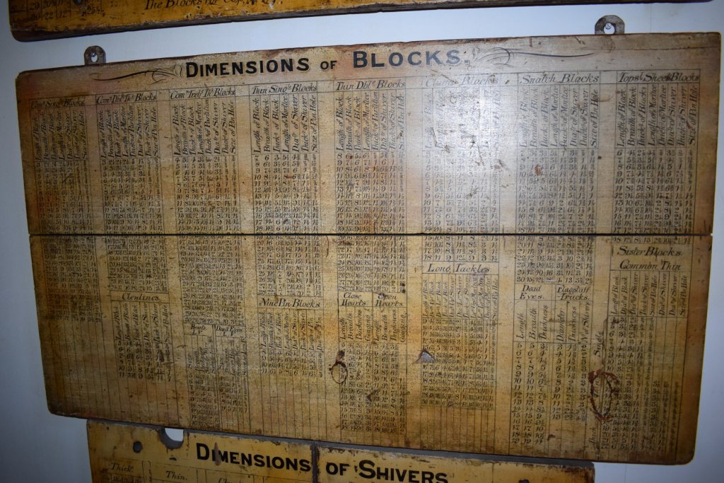
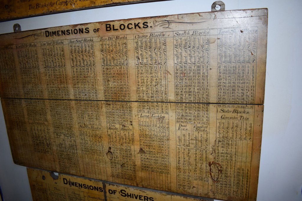
During a recent visit to Portsmouth, I walked through a gallery dedicated to the tools and equipment used by many of the traditional dockyard trades, and saw this board on the wall. I would believe from the style of lettering that it dates to the early 1800s, perhaps a little earlier or later. However, I would think that the information contained therein is unlikely to have changed very much at all from that of the times many decades previous to this. The photos are large files, and should expand considerably when clicked. There is a lot of useful information here! All the best, Mark P
-
- 5
-

-
Mast Lengths and their above deck heights for HMB Endeavour
Mark P replied to dashi's topic in Masting, rigging and sails
Good Morning Druxey; Yes, it is not the same, although I think that the details shown are very similar to at least one of the draughts shown in earlier posts. The date is very specific, which is helpful. Shipaholic, I agreed that my visit to the Library was for personal research. I cannot therefore post more pictures here, as who knows what may then happen to them. The Library staff were extremely helpful, though, and would be willing to take a digital scan and send it. This would avoid the photographic distortion present in my pictures. However, very inconveniently, they are now in the process of moving to different premises, and are very unlikely to reply to any emails, for many months. Which is not helpful. All the best, Mark P- 63 replies
-
- 1
-
-
- HMB Endeavour mast lengths
- above deck mast heights
- (and 3 more)
-
Mast Lengths and their above deck heights for HMB Endeavour
Mark P replied to dashi's topic in Masting, rigging and sails
Good Evening All; This is part of the draught referred to. I won't post it all for copyright reasons. I checked, and it actually says 'taken off in the single dock', not the wet dock. Memory plays up a bit, sometimes! It is definitely dated as mentioned, though. All the best, Mark P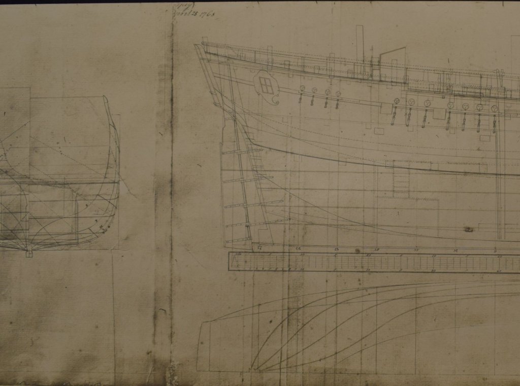
- 63 replies
-
- 2
-
-
- HMB Endeavour mast lengths
- above deck mast heights
- (and 3 more)
-
Mast Lengths and their above deck heights for HMB Endeavour
Mark P replied to dashi's topic in Masting, rigging and sails
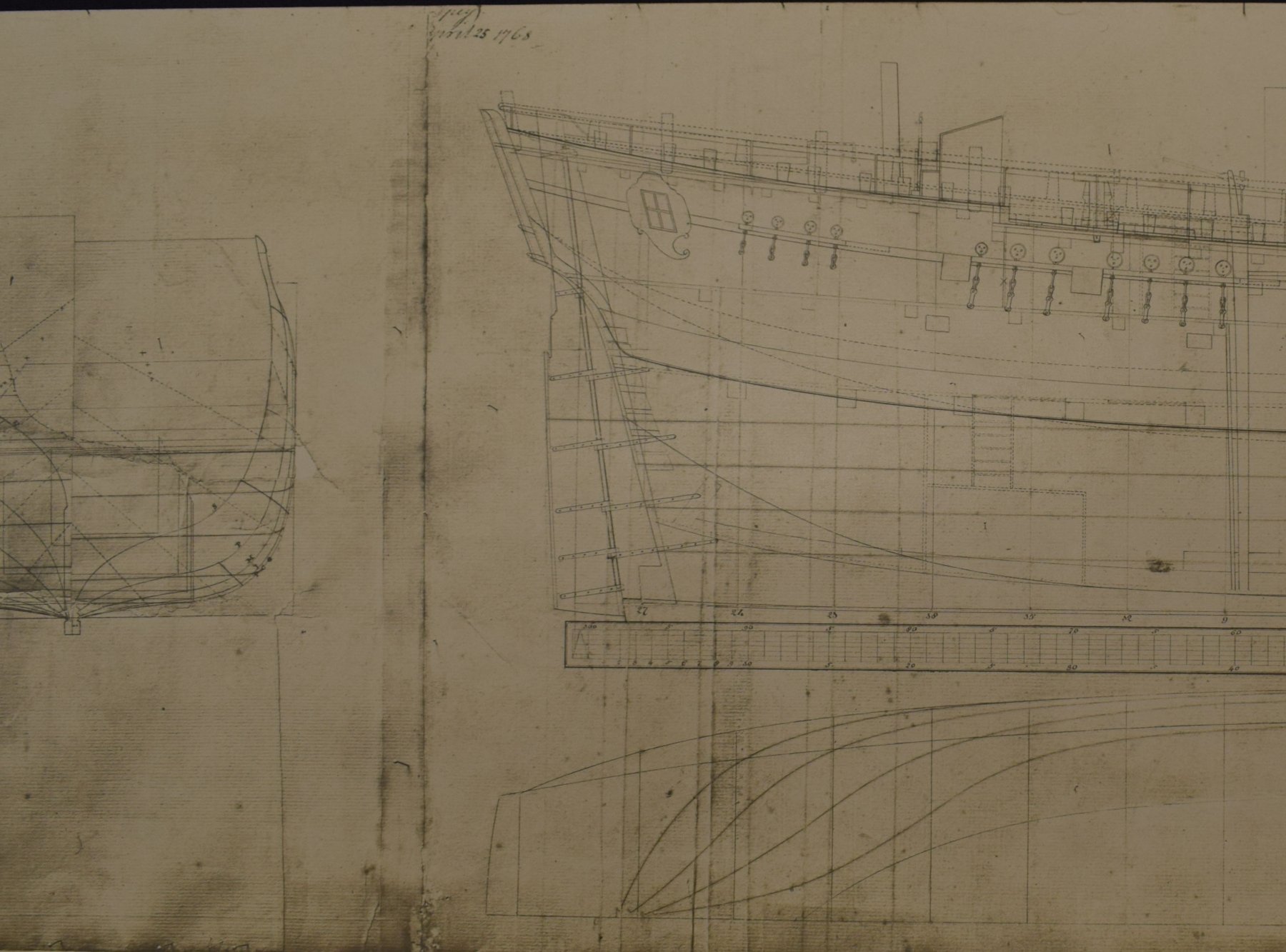
Good Evening Everyone; I recently visited the Naval Base at Portsmouth, with the kind assistance of the staff of the Library of the National Museum of the Royal Navy and the Librarians of the Admiralty Library, to view a variety of interesting documents. One of these was a draught of 'HM Bark Endeavour', described as 'taken off in the wet dock' and dated 25th April 1768. This lists her principal dimensions, and there is another word near the date, hard to read, of four letters, but it might say '?rey', which I would take to read 'Grey', as mentioned in previous posts, except that the 'r' looks more like a 'p', which would read '?pey' and I can't make much sense of that. Interestingly, this draught shows a tall, built up companion immediately afore the wheel, and a variety of dashed lines for the position of the rails and lengths of the mizzen channels. I will post a picture of part of her here, as it seems that it is not presently known widely, and it may be of use to modellers of the Endeavour. I don't have time right now to edit the picture, but I will do this tomorrow. All the best, Mark P- 63 replies
-
- 3
-
-
- HMB Endeavour mast lengths
- above deck mast heights
- (and 3 more)
-
Good Evening Spike; I wish you all the best with completing your model. The tackle at the rear is called the train tackle. When the cannon was fired, its recoil pushed it back within board. It needed to stay in that position while it was swabbed and reloaded. This was where the train tackle came into use. During this operation, it was kept taut so that if the deck heeled down towards the gun-port, the cannon would not roll while the crew were working on it. Once reloaded, the train tackle was un-hooked, and the gun-tackles (the ones on each side) were used to run the gun out ready for firing. Train tackles were not always issued as part of the gunner's stores, and even when available, were not always issued at the rate of one per gun. Concerning the breeching, I know little of French practice, but it looks from the illustration as though the breeching passes through the sides of the gun-carriage, which, as you say, is very different to English methods. I remember some other contributors here posting pictures of a replica ship, Danish I think, which was breeched in the same manner. I believe it was Tadeusz. All the best, Mark P
-
Hi Mike; I know that La Renommee is a bit later in time, but a very common phrase in ship-building contracts from the late 17th century/early 18th, related to gratings, is that they are 'to vent the smoake (sic) of the ordnance'. The gratings, if this is their purpose, are therefore designed for something moving upwards, not downwards. Although the waist is open, I would suggest that a fully planked gangway over the cannon would hinder the escape of the smoke, so the above hypothesis is reasonable. In this case, the prime function of the gangways would be for sailors to walk along. with this in mind, flush gratings would seem most likely. All the best, Mark P
-
Hi YT; A cleat in this context is a metal or wood object which is used to make fast (belay) a rope from the running rigging, so that whatever is at the other end of the rope will not move. They come in all sorts of sizes. Think of something like the top of a longhorn steer's skull with the horns poking out to each side, both in a straight line. The rope is passed under the horns, and over the middle, around and around in a figure-of-eight pattern. They were fixed to the ships' sides, to the masts, or to the shrouds (this latter type are called shroud cleats) A cleat is also the name for a small timber batten, used to hold something in place. All the best, Mark P
-
Hi Kevin; Thanks for posting this. She is such a beautiful sight! Looks like she can sail very close to the wind, too. All the best, Mark P
-
Hi James; That is indeed an impressive array of models. I presume that you have seen the large model of King George V in the NMM. Wouldn't quite fit on a cupboard, though! All the best with your modelling. Mark P