Mark P
-
Posts
1,774 -
Joined
-
Last visited
Content Type
Profiles
Forums
Gallery
Events
Everything posted by Mark P
-
 Good Evening Mark; Thank you for taking the initial steps with photo-etching, so that those who come after can learn from your experiences, and most importantly, any mistakes! Keep up the great posts! All the best, Mark P
 -
Good Evening Jason; Druxey is quite right. I will add a little bit as well. Models of ships were sometimes fitted with launching flags. A short plank is fixed over the hole in the mast partners, athwarthips, with a hole cut through it. The hole is much smaller than that for the mast. The plank does not cover the mast hole completely, not being wide enough to do so, so a portion of the mast hole is visible both afore and abaft of the plank. You may be right about the relative position of the flags, but remember that the ship was launched backwards! All the best, Mark P
-
Good Morning Siggi; The picture of Victory is interesting. If you look closely at the gunports, you can see that a narrow strip of wood has been nailed into the bottom of the port in the ship's side, to fill the space where the rebate would have been. As an example of proper practice in the 18th century, I would not refer to the present Victory, though. As you probably know, she has been repaired and patched so many times that there is very little original left, and I would doubt that the present gunport lids are faithful replicas of those she had at Trafalgar or earlier. All the best, Mark P
-
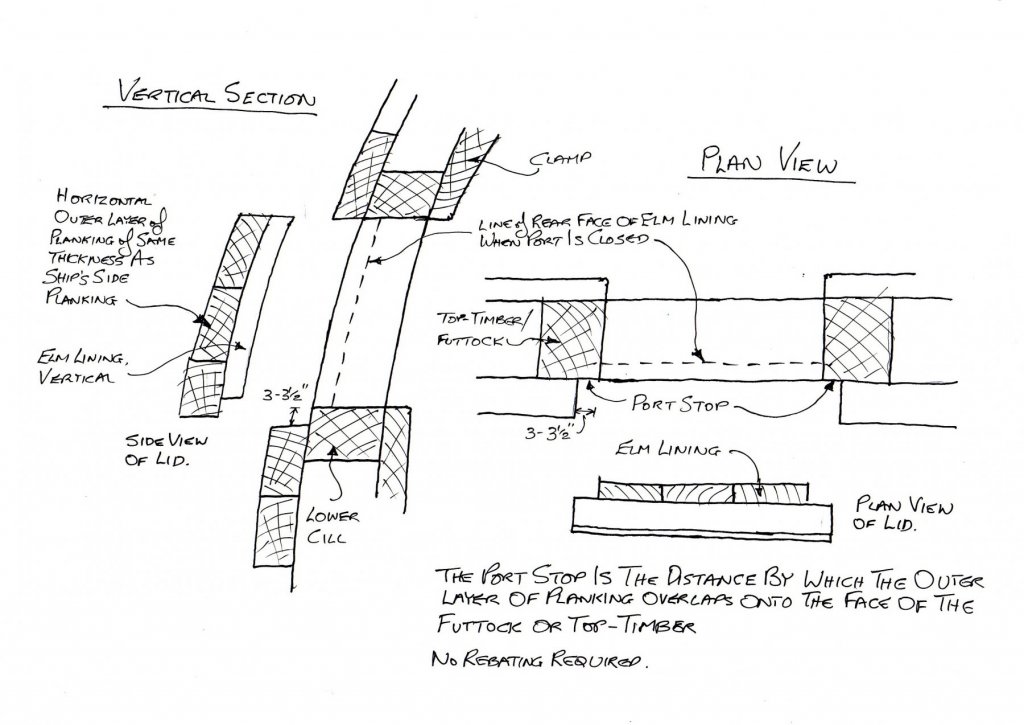
Greetings everyone; Having seen Steel's description, sent by Druxey, I can now present a solution which we both agree is the most likely one. Steel specifies that the port stops must be a minimum of 3 to 3 1/2 " depending upon the rate of the ship. The contracts I quoted in an earlier post state that the outer planking of the port lid is the same thickness as the outer planking of the ships side, and that this is backed up by an elm lining laid vertically and nailed to the outer planks of the port lid. By the way Mark (SJ Soane, see post above) I never envisioned a rebate in the frame timbers. A misunderstanding somewhere along the line. Siggi's left hand sketch in post 201 was as I interpreted the contract description. This has now been slightly refined, see attached sketch. The stop distance given by Steel is the distance by which the outer planking of the port lid overlaps onto the face of futtock or toptimber. He also states that the lining is to be 1" to 1 1/4" thick. This will be the thickness of the elm lining boards on the inner face of the gunport lid. No extra work required, no need to form rebates, no need for the stated dimensions of the gunport to be reduced by a separate lining, and no need to fit the separate lining. All the best, Mark P Gun port sections002.pdf
-
Hi Paul; The solid bar is a method of making the chains which was used before they were forged as a link, which was a later development. All the best, Mark P
-
Good Morning Druxey; Your point re the timbers being thicker for the ringbolts is a good one, I had not considered that; but it does not negate my proposition, it would be an additional reason to need a thicker timber, as well as leaving part of the timber exposed externally. My reasons for being certain that there was no lining of the timbers forming the sides of the ports are several: 1 - Firstly, I have both read and photographed many, many contracts for building Navy ships in merchant yards, over a hundred of them. I have transcribed over twenty of these. Whilst some of them detail the construction of the port lids as shown in the extract above, not one of them mentions separate linings being fitted around the ports. Whilst the very early contracts can be brief, the mid 18th century ones onward generally go into great detail, and I cannot believe that they would not specify a separate lining if such was expected. The builders would be justified in omitting it, thereby saving a considerable cost to themselves in time and materials, and the Navy Board would be unable to enforce them being fitted. 2 - Why would there be any need to add separate timbers, which would take time and money to do, when a stop can be formed as shown in Siggi's sketch, which is in complete accordance with the contract extracts in my previous post. This method of construction gives a good seal against water, and requires no additional work operations. The Navy Board was very strict about reducing costs wherever possible, and I cannot believe that they would have sanctioned an un-necessary process of fitting wood around all ports which had a lid. If it is believed that the ports were lined to prevent the gun-crews getting splinters in their hands from a sawn finish to the timbers, there is a counter to this in the contracts. These frequently state, and presumably this was universal, that all the beams, knees, standards and planking of the sides were to be planed, with the corners struck with a bead. The timber was also painted, normally with three coats of paint, periodically refreshed. A relevant point here would be what happened to the ports in the waist, which had no lids? 3 - The builders' contracts also frequently specify, when dealing with the ships' framing and fitting of the gun-port cills, that a certain amount of timber must be left beyond the birds-beaks cut into the timber for the port cills. They often then continue by saying that when the port is cut out to its bigness, no sap or wain can be left in the timbers. This can only really refer to any minor trimming or smoothing of timbers to leave the hole the exact correct size as specified (see also item 4 below) 4 - I have checked the sizes of the ports as shown on the framing plans of various vessels against the port sizes listed in the contracts. In all cases the dimensions matched. Any lining fitted would therefore reduce the size of the opening below that specified. To my interpretation, this is another good indication that no linings were fitted as separate pieces. 5 - There is no mention of stops as separate pieces of timber in any contemporary work of reference which I have seen. Can you post a copy of the section of Steel in which they are listed. How exact is Steel's description, is it clear to what he is referring. Falconer makes no mention of stops, neither are they listed in the copy of Steel's 'Vade Mecum', of both of which I have (pdf) copies. 6 - The excavation report of the 'Colossus', part of which dealt at some length with a gun-port on the wreck of that ship, includes colour photographs of the interior view of the port, with a curved, projecting piece of timber fastened inside the lower cill, against which the gun carriage's front end would have hit when the gun was run out. This is quite likely to be referred to as a stop, although this depends upon Steel's description of this, and the dimensions he gives for it. I would believe that items 1 to 4 above add up to a considerable set of reasons for separate linings to form stops being neither done nor necessary. All the best, Mark P
-
Good Evening Siggi; Your left hand sketch shows exactly how I always understood the ports to be formed, and agrees with the descriptions in both contracts. The size of the port is measured between the timbers of the frame. I have to respectfully disagree with Druxey's sketch above. It is much simpler to build the ports as in Siggi's sketch. No need to add a lining around the port. Other contracts stipulate that the top-timbers which make the sides of ports are to be sided 1" more than top-timbers which do not form ports. This would seem to be needed because part of the timber was to be left un-covered to form the stop for the port-lid, whilst still leaving a good width of timber to fix the ends of the planking to. That is full-size practice. There are more than enough precedents in contemporary models for Siggi to make his gun-port lids without a rebated edge. This was done, though, only for simplicity in the making of the model. The two pictures in post 201 above show the reality. All the best, Mark P
-
Greetings again Siggi; See below an extract from a contract for 'Newark', an 80 gun ship, dated 1693. This gives more detail of the gun-port lids and their eye-bolts etc. Port Lids To make all the Port Lidds on each Side for each Deck, & through the Bulkheads and for the Chases afore and abaft with Such Thickness of Oak Planck, and Prussia deals as the Planck is where they Respectively fall, to line them with Elme Board and Full Naile them. To Hang them with Substantiall Iron Hooks of Such Length as may Come within Two Inches of through the Ship’s side, and the Hinges to Reach within Three Inches of the Lower Edge on Each Port Lidd Bolted and Fore locked aloft. And to fit to each Port Lidd of the Lower deck Two Inside Substantiall Shackles and one neare the Lower Edge of the Port without Board, all the rest of the Port Lidds to have One only within and one without, and to well Belay all of them with good Rings, and Forelocks. All the best, Mark P
-
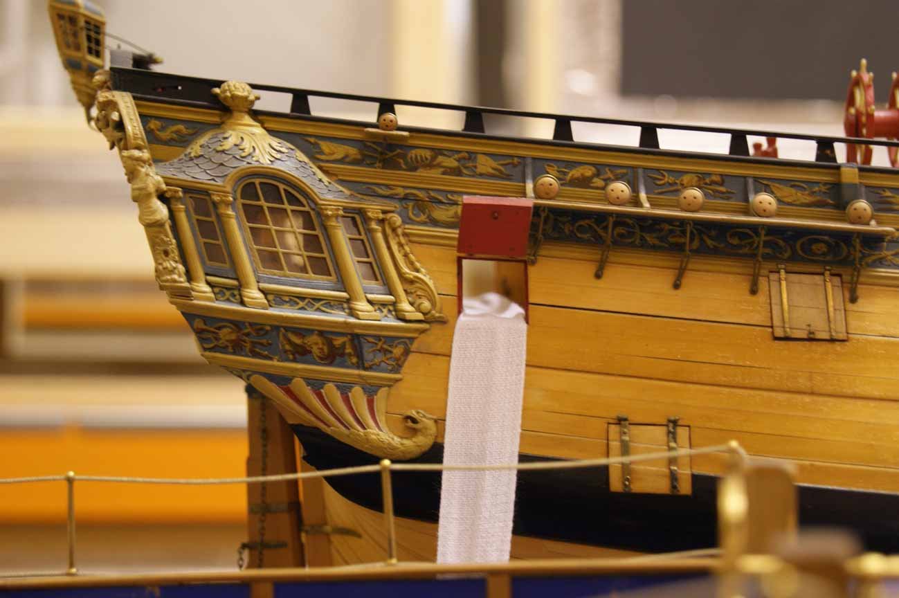
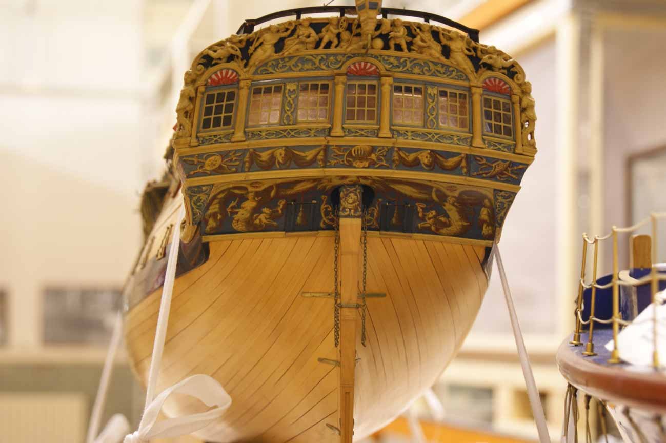
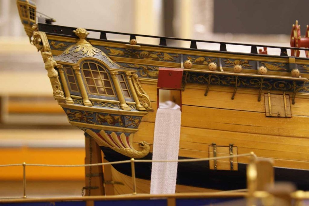
Greetings Siggi; You are making a very good job of building your model, very neat work, and a beautiful figurehead. Concerning the debate about port lids, see below an extract for a contract to build a 50 gun ship. This is dated 1692, but I have seen the same thing on later contracts. This clearly states that the ports are to be built with the same size planks as the outer layer, and then lined with a layer of Elm. A very important point here is that the sides of the ports were formed of substantial timbers, the verticals being either futtocks or toptimbers, and the cills of substantial oak pieces. By leaving the planking stopped short each side of the port, and below, a rebate is formed without any need for lining the ports. I have seen many, many listings of port sizes, and they are all the same, they never mention any slips or linings to form a rebate. As the extract below makes clear, the outer layer of planking is the same as the ship's side at that point. It is not possible to then have any other interpretation except that the elm lining (which would be vertical planks) being fixed behind this outer layer, must fit within the gap between the main frame timbers. forward to be Twelve Inches Square at the head. To make and hang all the Ports on each side upon Each Deck and in each Bulkhead with the same Size of Planck ye Side is wrought with. To lyne the same with Elm Boards well nailed. To build a fair head with a firm and Substantiall In the gallery, there are pictures of models which I have taken at the Science Museum and the NMM archives. All of these show a rebate for the port lids. All the port lids on models seem to be made of a single layer, though. This is presumably to keep it simple, as many are kept shut. All the best, and keep up the impressive work! Mark P
-
HMS VICTORY 1765 by albert - 1/48
Mark P replied to albert's topic in - Build logs for subjects built 1751 - 1800
Congratulations Albert; I am very glad that you have taken on such a vessel. I have always felt that it is such a matter of regret that the original, beautiful decoration of the Victory was removed just before the battle of Trafalgar. Such a shame that the battle was not fought a few years earlier, because then all the visitors to Victory in Portsmouth would see and realise just how attractive these old-time ships were. I presume that you are aware of the scale carving of her figurehead at the NMM, and the model of her at launching, showing her (incorrectly) on the ways. (She was floated out from dry dock) Anyway, I wish you the best of progress in all of the build, which I will follow with great interest. All the best, Mark P -
Having also purchased a copy as soon after publication as funds permitted, I can also vouch for the excellence of this book, and the value of the wealth of photographs which it contains. Very much worth the cost, even with postage to England added. Happy reading! Mark P
-
Evening Antonio; The boom referred to is, as Frankie says above, the studding sail boom. I assume you know what these are. Whether they were in use, or run in on the yard for storage, the inner end was lashed to the yard to prevent it moving. There was normally a hole drilled through the boom near its heel to allow the lashing to pass through the boom for better security of the lashing. All the best, Mark P
-
Clewline attachment to Topsail yard,HMS Cheerful
Mark P replied to davyboy's topic in Masting, rigging and sails
Good Evening Dave; Depends on the size of ship and the date. Can you give us a bit more information. All the best, Mark -
Morning Mark; You are correct about the ring on the cascabel for the breeching rope. It appeared around 1790, I believe. Prior to this, on some ships, a thimble was seized in a short strop around the cascabel to provide an eye for the breeching rope. The thimble was placed above the cascabel. All the best, Mark P
-
Evening Mark; Yes, this is an awkward little spot. You are right about the little triangle, which abuts the rear face of the wale planks on the outside; the side of the final curved end of the bottom planking on the inside; and sits under the counter planking at the top. This latter seam is then covered with the tuck moulding. The end of wale is rounded on its bottom corner to fair in with the curve of those last few inches of bottom planking. ie the bottom end of the wale is a curve when viewed from abeam. The amount of curvature required is controlled by the vertical difference between the height of the bottom of the wale, and the underside of the tuck mould. This distance seems to vary from ship to ship. In Endymion, below, it is perhaps greater than in some others, producing a larger radius curve than you will need to use for Bellona. It might be the angle of your picture, but it seems that you might not have left the counter planking with an edge for the bottom planking to butt against. The last little curved part of the bottom plank which is against the triangle was often sawn from the solid. The pictures of Endymion below show it quite well. All the best, Mark P

-
Evening Mark; I am not sure where the drawing came from, but just in case you are not aware of this, it is not accurate. My apologies if you already know, but the bottom of the spirketting is wrong on both decks. The waterway has a hollow curve, but the spirketting is flat. It would waste an awful lot of wood and be a lot of work to produce it as drawn. All the best, and keep up the inspirational work! Mark P
-
Hi Phil; Further to the replies above, in the mid 1600s the gun-ports in the waist did have port lids. However, slightly later in that century they were done away with, largely to save money. All the best, Mark P
-
Caroline's bottom
Mark P replied to GrantGoodale's topic in Building, Framing, Planking and plating a ships hull and deck
Greetings everyone; Thank you John, for such an informative post about the 'Teredo Navalis' worms. In the days before copper plating became standard (it appears to have been used by Liverpool-based merchant ships before the Navy adopted it, as I have seen references to a letter recommending it to the Admiralty 'as has been done in Liverpool merchant vessels these last eight years') most ships were 'Sheathed', ie their bottom was covered with a sacrificial layer of timber planking, fastened with sheathing nails. These were presumably of copper, and could well have been closely spaced. As the timber was sacrificial, it had to be removed and replaced at regular intervals, which would account for the meaning in Druxey's post above, that it would 'last extremely well until Spring', that is until the timber needed to be replaced. A layer of felt and hair was placed between the sheathing and the actual ship's bottom planking. The nails in the waterline area would be seen as the ship rolled, and would look like green peas, as per comments above. Those lower down would only be seen in the dockyard, so their different colour would not be what the sailors generally saw. I bet somewhere out there a worm is morphing into one which will munch its way through fibreglass! Eighteen footers beware! All the best, Mark P -
Evening Fidlock; Iron cannon were painted black. As were anchors, deadeye straps, and all other exposed ironwork. These last items were normally listed in painters' contracts. Cannon were the property of the Ordnance Board, who were independent from the Navy, and organised the painting themselves. All the best, Mark P
-
Greetings everyone; There are some interesting ideas put forward here. Frankie's diagram is quite correct. In order for the mast heel to travel 100 feet, the block in the end of the pendant must travel 200 feet. However, there is one point to keep in mind here, which is why was the top-rope not unrove once the topmast was hoisted. This could be for safety reasons, in case the fid broke (in later times a preventer fid was fitted to counter just this event) But in the Restoration Navy, and later, it was customary during stormy weather to lower the topmasts, but perhaps they did not remove them and stow them away. This was done to lessen the weight at high level, and reduce the roll of the ship. There are some famous paintings showing ships in stormy weather with lowered topmasts. I will have to dig one out and see if the masts were removed or not in these circumstances. Perhaps they were lowered enough for the topmast trestle-trees to be above the lower mast cap, and the heel of the mast was lashed to the lower mast to prevent movement. All the best, Mark P
-
Hi Louie; The pumps were connected to the ship's side by removable timber tubes, square in section, which were known as 'dales'. These were taken to a scupper, which, if my memory is not playing me false, was sometimes larger than the other scuppers. The dales were presumably stored near the pump. The pumps were sited near the main mast, as this was in what was called the 'well', and area kept clear right through the hold, down to the bottom of the ship, so that the amount of water coming in could be easily assessed. This was also the lowest point in the ship, and the timbers were sometimes cut away to allow the lowest part of the pump to scoop up water from below the tops of the floor timbers. Some systems of framing left a gap between the opposite end of the first futtocks (navel timbers as they were called at that time) which allowed the end of the pump to be sited at the end of the navel timbers, against the keelson. All the best, Mark P
- 12 replies
-
- 2
-

-
- chain pumps
- dromons
- (and 2 more)
-
Good evening all modellers! I am not sure if this has been mentioned here before, but if so please forgive me, as I did not see it. I think that many of you will be interested in a project to build a full-size replica of the Lenox, a 70 gun warship, which was one of the 30 ships programme from 1677. Richard Endsor, whose books on Restoration warships are a wealth of beautifully illustrated detail, is one of, or the, founding member(s) The project aims to build the ship in one of the original dry-docks at the former Deptford Royal Dockyard on the River Thames in London. The project is now well under way, although it will probably be some years before the keel is laid. Search for 'The Lenox project' for more information. I sincerely hope that the project continues to move forward, and is successful. All the best, Mark P
-
Greetings everyone; I have just finished reading 'Kings of the Sea', by J D Davis, and I have to say that it is a real revelation. This is very well written, and every page makes it clear that the book is the outcome of many years of patient and very thorough research. The subject is the influence of Charles II, and his younger brother, James, on the history and development of ships and the Royal Navy. A great deal of new material is included, and the reader discovers just how deeply Charles was involved in even the day-to-day running of the Navy, how important it was to him (and his brother) and how little of all this has been discussed in biographies of this king. Charles shaped both the ships of the Navy, and the ethos of the men who crewed and directed them, far more than he has ever been given credit for. The King's (and his brother's) role in the appointment of officers, including many warrant officers, is shown in detail, as is his interest in, and control over, where they should be deployed, and the orders given to the captains. Davis also brings a new consideration to the sources for the development of the Navy at this time, mostly Samuel Pepys, whose diary and journal have been mined many times for information. The author gives an example of a meeting which Pepys described briefly, giving an impression that things happened only because of his influence. Nearly all the time, Pepys is the only available source for such information, leaving little choice except to take him at his word. However, in this case, Pepys' own brother was also present, and kept his own minutes, which show that more people were present, that there was a prolonged and lively debate, and that Pepys played almost no part in the proceedings. The brother's record is included amongst the great archive of material which Pepys left to Magdalene College, Oxford, where it still resides. Davis seems to have read nearly all of it, over the years, and demonstrates that future authors should perhaps be more critical of Pepys' memoirs than has hitherto been the case. Which is still not to deny that Pepys also played an important part for many years. This book brings something new and important to the knowledge of the Restoration period's Naval history, and I cannot but predict that even the most widely-read and knowledgeable reader will know and understand a great deal more by the time they reach the end of this most deserving work. All the best, and happy reading! Mark P
-
Sail design for 18th-century longboat?
Mark P replied to Cathead's topic in Masting, rigging and sails
Thanks Roger; I guess that blows my theory out of the water then! Good to hear the facts from someone who knows through experience. All the best, Mark -
Sail design for 18th-century longboat?
Mark P replied to Cathead's topic in Masting, rigging and sails
Hi Dowmer; Thanks for letting me know. I think that when I clicked on this topic, I was taken to an earlier point in the discussions, and missed some of the latest posts. Has a sailor commented on the practicality of this, rather than only landlubbers. The boat's momentum would keep it moving ahead, and the wind on the headsails turns the bows in the direction that they need to go. For a brief while, the rudder does nothing. All the best, Mark P