Mark P
-
Posts
1,774 -
Joined
-
Last visited
Content Type
Profiles
Forums
Gallery
Events
Everything posted by Mark P
-
 Good Morning Ferit; If you are talking of 18th century ships, or earlier, I have seen frequent mention in lists of bo'suns' stores to candles, and they are mentioned in other documents. Oil would be a volatile substance to have near a flame on a constantly-moving ship made of wood. I would exclude oil completely, and show candles. However, for 19th century merchant vessels, oil might have been used. I cannot say. If this is your area of interest, try looking under the National Maritime Museum's online collections site. They will certainly have some ships' lanterns there. All the best, Mark
 -
Good Evening Gary; Thank you for the message. I will look into this cyclone idea, and see if anything like it is available over here. All the best, Mark P
-
Good Evening Gary; That looks like a very well set-up workshop you have made there for yourself. Your library looks really impressive too. I recognise the set of Model Shipwright, and quite a few of the books, but some of them I don't know. I am jealous (in a good way!) of your dust extraction set-up. I spent some time trying to get mine to work properly, but so far without much success. Thanks for the pictures. All the best, Mark P
-
Welcome to the forum Dean; My first ever project was a 'Keil-Kraft' balsa glider. Disappeared long ago. I once started on a 6ft B-17 flying fortress, but ran out of steam (ships took over) Whatever you choose to build, I wish you all the best. Mark P
-
How many riders?
Mark P replied to Bluto 1790's topic in Building, Framing, Planking and plating a ships hull and deck
Good Evening Jim; Whichever you choose, I wish you happy building! And happy reading of your book when it arrives. Good Evening Druxey; You are right, of course. Sole was more usual in the 18th century. I would just like to re-assure you that I am completely sober (hic!) Only drunk from reading quite a few 17th century contracts, wherein 'shoal' is more customary. All the best, Mark P -
How many riders?
Mark P replied to Bluto 1790's topic in Building, Framing, Planking and plating a ships hull and deck
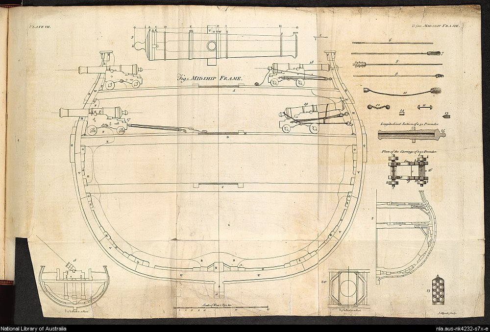
Good Evening Jim; Your coloured arrows are correct: green equals the floor rider; red is the first futtock rider and blue is the second futtock or breadth rider. The coloured-in pieces on the orlop deck drawing are indeed the tops of the riders. Another point which might be worth bringing to your attention is standard knees. These are knees which are 'upside-down', and are located on all the main gun-decks. They sit on the deck, and are fixed to the ship's side. On the left hand side of Falconer's midship section, you can just see two of them, one behind each of the guns. A 74 had something like 10 of these on each side on each deck. They were not fixed directly to the deck, but to a 'shoal', which was a 3 inch thick piece of plank laid over the deck, and it was on top of this that the standard was located. The shoal would often stop short of the ship's side so that any water on the deck could run along the waterways to the scuppers. Standards and shoals are rarely seen on contemporary models, nor are they shown on McKay's drawings of 'Leopard', but depending upon your desire for accuracy, you might wish to include some. All the best, Mark P -
How many riders?
Mark P replied to Bluto 1790's topic in Building, Framing, Planking and plating a ships hull and deck
Good Evening Jim; With a midship section without any other details showing it could be looking forward or aft, it would look the same. As viewed, I meant starboard to be the right hand side. There are no knees shown on that side to confuse the issue. All the best, Mark P -
How many riders?
Mark P replied to Bluto 1790's topic in Building, Framing, Planking and plating a ships hull and deck
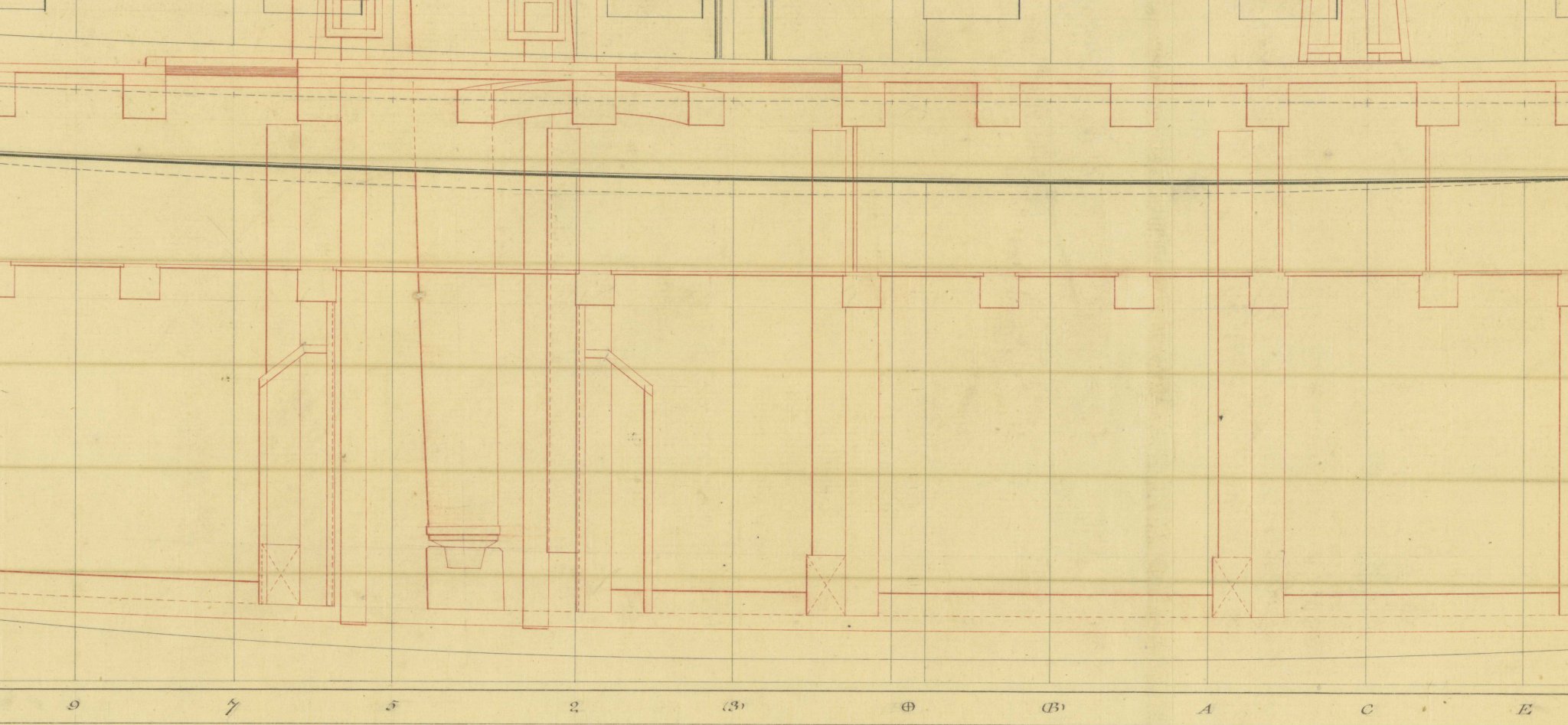
Good Afternoon Bluto; I agree with Druxey's comments, you should certainly read at least one of the books he mentions, and preferably at least the last two, if you need to understand riders somewhat better. However, one comment is that the midship section you posted is taken from the book 'The 50-gun Ship', by Rif Winfield. If you have not got this, I would advise you to do so, as there are some further drawings in it which show the decks in isometric views, all very clearly drawn by the very talented John McKay. Unfortunately, the hold is not included in this series, but the view of the orlop does show the ends of the riders poking through. See below an excerpt from a draught of the Stirling Castle, a 64 gun ship, but the principle is the same. Riders comprised floor riders, which straddle the keel; first futtock riders, which run alongside the previous ones, but started at the keel and stopped at the orlop deck beams; and second-futtock or breadth riders, which began at the end of the floor riders, and extended up to the gun-deck beams. In the draught, there is a pair behind/below each shot locker, although the forward one seems to have no floor rider, then again just aft of the midship station; just forward of station A and just forward of station E (the latter has no floor rider) Note that although the 'X' marking the floor riders appears to cut into the keelson, this is a draughting convention. In reality, the floor riders were bent up over the keelson. See also below a plate from Falconer's work, which shows the midship section and riders (starboard side is clearest) All the best, Mark P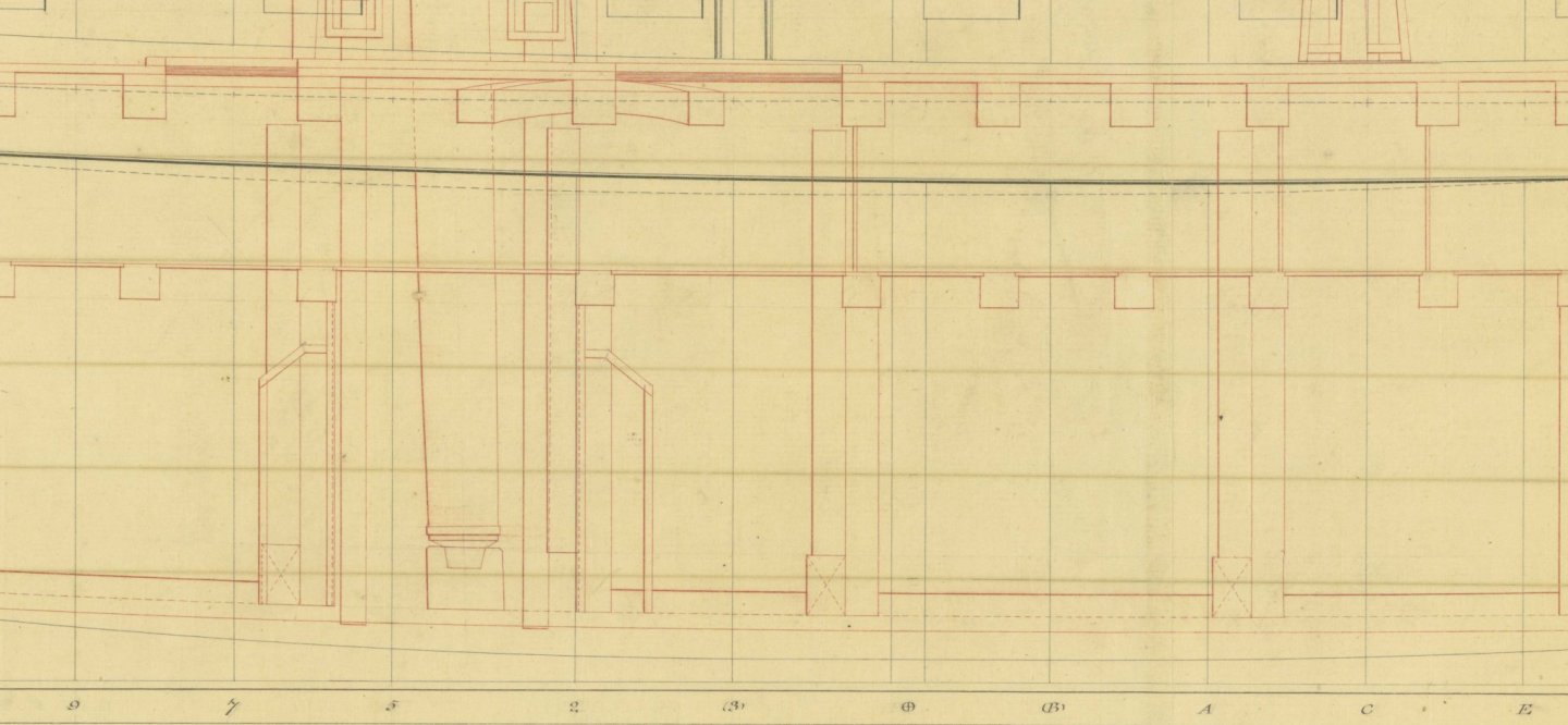
-
Good Morning Vulcan; I would suspect that oars would be lashed to the thwarts (different boats would almost certainly have had different lengths of oars. The contracts for supplying these are very specific about lengths, of which there are a large variety) and the masts and yards would perhaps be also. These latter, though, could also have been lashed to the skid beams or the spare topmasts etc on which the longboat was stowed. The rigging and sails were probably removed and stowed in a sail room or the bo'sun's store room. As the boat might not be used for a long time, anything left in the bottom of the boat would be exposed to damp, and would only dry slowly, leaving them vulnerable to rot, especially the canvas sails. However, if you are depicting the boat being hoisted out, I would believe that all the masts and rigging would be brought out of store, and put on board before she was hoisted, ready to be stepped and set up once she was in the water. Some boats had lockers under the seats, and perhaps in the bow. Some of the rigging may have been stored in these, in which case it would be unseen during the hoisting. All the best, Mark P
-
Good Evening Pop; If you are referring to the very early days of artillery on ships, Henry VIII up to the early 17th century, the gun carriages were very different to those with which we are more familiar. Some of those recovered from the Mary Rose were designed to lay flat on the deck, strapped to a baulk of timber, with a removable breech section, which was wedged in place before firing. As these were the lighter ones, they may well have been used on the more upwardly-curved parts of the upper decks. I am not sure how the recoil was contained. Look up the guns in the Mary Rose museum. This design would be unaffected by any sideways lean from the angle of the deck. This degree of curvature would not have been repeated on the lower decks, where the heavier guns were located, because these decks were actually built with a step downwards towards the stern, giving a split-level deck. This was very common prior to around 1620. When full-length unbroken decks were introduced, they became known as 'over-leaping' decks, from which we derive the word 'orlop'. In the early 17th century, this term was applied to all continuous decks. A ship could contain 2 or 3 orlop decks, known as the upper and lower orlop, etc. How far into the Elizabethan era this type of gun continued in use I am not sure, but shipbuilders gradually reduced the amount of sheer (curvature) so any problems caused by this would have diminished. And for large parts of those times, and well into the 17th century, guns were often not fitted to the upper most parts of the stern or the forecastle on most ships. All the best, Mark P
-
Chocks for futtocks
Mark P replied to allanyed's topic in Building, Framing, Planking and plating a ships hull and deck
Good Evening Allan; Regarding wrecks, there are attempts being made to authorize the salvage and/or investigation of timbers from the Anne, burnt on the beach to avoid capture after being damaged by cannon fire in the Battle of Beachy Head in 1690. Similarly, the remains of the London, which blew up in the Thames Estuary, killing most of her crew and their families who were aboard, whilst anchored at The Nore in 1665. Apparently, a very well-preserved gun carriage was recently recovered from near the latter ship. Something to look into! All the best, Mark -
Converting a Backyard Shed into a Model Workshop
Mark P replied to Hank's topic in Modeling tools and Workshop Equipment
Good Morning Hank; I wish you all the best with your shed conversion, and many years of happy modelling! I have to say that to almost anyone living in England, the idea of a 'garden' as big as yours is unthinkable. So much space! I know America is a big place, but you seem to have half of it in your back yard! All the best, Mark P -
Good Evening Bruce; Unless I have misunderstood your last post, there is no mistake in your earlier postings. The date of your letter is post 1750. I only mentioned the previous New Year custom as a possible reason for a mistake on Rif Winfield's part (or his assistant) All the best, Mark P
-
Good Evening Bruce; Thanks for the clarification. Thirteen months would seem an excessive delay, certainly. I think the most likely answer is a typo in Rif Winfield's book. It should probably read that the work was done in Feb-May 1778, not 1779. One factor that may influence this is that until 1750 the official New Year began on the 25th March, Lady Day, one of the year's quarter days. So prior to 1750, any documents dated from January to 24th March in any year would nowadays be dated to the following year. It is possible that this mindset may have caused an error to creep in to the entry. With so many dates to think of when compiling his book, and many prior to 1750 needing to be updated, I would not be surprised if this was the case. All the best, Mark P
-
Good Evening Bruce; It is likely that your reference is the date of the decision to order her to be coppered. What is the date of the letter you are quoting? It would seem normal enough for the order to precede the action by some months, which would seem to be corroborated by the fact that the letter you mention changes the dockyard where the work is to be done, to Chatham as mentioned in Rif Winfield's book extract above. The actual work being carried out was then dependent upon a dry dock being available. Bringing in a new ship to work on was normally planned some time in advance, to take place as soon as work on a dock's current occupant was completed. As the book lists the coppering being commenced in February the following year, this would seem consistent with the letter you quote, if it is dated a few months prior to then, in Autumn or late 1778. All the best, Mark P
-
Good Morning Phil & Edward; Rif Winfield's book British Warships of the Sailing Navy lists Triton as being coppered at Chatham from February to April 1779. This is probably taken from the ship's progress book in the National Archives, which lists the main dockyard events in the lives of all Navy vessels. If you are depicting Triton as first launched, I would not copper her. All the best, Mark P
-
Further to Richard's reply above, the main drawback to the use of copper was its electrolytic reaction with seawater and the iron bolts holding the timbers together, causing rapid corrosion and weakening of the fastenings. This was overcome by replacing all of a ship's bolts below water level with ones made of a bronze-based metal, or 'mixt metal' as it was called. I believe that 'Muntz metal' was another name for this. Once the Navy Board and Admiralty had agreed the necessity for this, and swallowed the expense, a programme of coppering all ships as they came into dock for routine maintenance was adopted. This programme was well underway by the mid 1770s, and by 1780 it is safe to assume that all Naval ships were coppered. Further interesting points are that coppering had apparently been used for a number of years prior to the Alarm experiment, by Liverpool-based merchant ships. And when the warrant for coppering Alarm was sent to Woolwich dockyard, it gave strict instructions that all workmen involved were to be publicly gathered and 'that they may be in no doubt', were to be told that any attempts to embezzle or secrete (steal, basically) any quantity of offcuts of copper would result in instant dismissal, and being proceeded against with the full force of the law. Copper was valuable stuff, and the temptation to men whose pay was months or years in arrears must have been high. All the best, Mark P
-
Thanks Alan, not just for the continuing build log, but also for the photography article. Full of good advice. Wish I could have been there! As for having a meeting in a tool store: a very canny move on somebody's part! I really, really wish I could have been there! All the best, Mark P
-
Good Evening all; Chuck's comments about the amount of waste are very true, if the situation in the States is anything like that in England. I have purchased or been given boxwood from trees grown here, and there are a lot of sections with wild grain; clusters of small knots; large knots; bent at all angles branches; and twisted grain, like a rope. The bent parts can, sawn with some care, provide compass timber, which is very useful, but the time required is not likely to be economical compared to the small amount of timber which results. In all the other cases, the wood is good for nothing, really. During seasoning it will often distort to a remarkable degree, and could not possibly be sold on. Frequently, the wood contains dark markings, or streaks. I could show you pieces of boxwood (I know it is boxwood because I saw it in the tree, and it still had leaves on when I collected it) which you would swear were pine by its striped appearance as seasoned timber (the weight makes it clear it is not pine, though!) I have discarded about half of all the boxwood I have bought. That still leaves a good quantity, but I would not want to do this commercially. I wish Chuck all the best with this.
-
Tailing deck beams
Mark P replied to allanyed's topic in Building, Framing, Planking and plating a ships hull and deck
Good Evening Doug; Thank you for your post. If the knee was seen more as a method of fastening the beam securely to the ship's side, then its substitution by a dovetailed joint would seem reasonable enough. Thank you also Druxey, for mentioning the Swan volume. David Antscherl's books are indeed a valuable source for any modeller, and well worth obtaining. All the best, Mark P -
Good Evening Gentlemen; Thank you Brandon for the original posting and info, and Don & Gregory for the follow-ups. I have looked in the British Library catalogue, and there are actually three editions of this book, dating from 1747, 1757 & 1775. I will take a look at the earlier two editions and see what Mr Robinson had to say about cannon and mortars in them. All the best, Mark P
-
Tailing deck beams
Mark P replied to allanyed's topic in Building, Framing, Planking and plating a ships hull and deck
Good Evening Allan; I hope you are enjoying your labours. I understand what you mean about doing it for love. Another item of interest with deck beams, which no-one will expect you to replicate, not even yourself, is this: alternating beams were laid 'top and butt'. This was the practice of having the root end of the trunk from which the beam was sawn laid alternately to port and starboard. This was because the root end was tougher and more resistant to rot, and meant that, all other things being equal, there would not be a weakness caused by a run of beam ends rotting at the same time. A further precaution was to drill a horizontal hole into the heart of the beam's ends, and then insert a red-hot iron in the hole, charring the wood, which also helped prevent rot. In addition, a further hole could be bored upwards from the underside of the beam, to intersect with this horizontal hole, thus allowing the circulation of air to help dry out any damp in the beam end. All the best, Mark P -
Tailing deck beams
Mark P replied to allanyed's topic in Building, Framing, Planking and plating a ships hull and deck
Good Evening Allan; It does indeed refer to dovetailing, as Druxey says. The beams were normally dovetailed on the end, and the dovetail was let down around 1" into the top of the clamp. I'm not sure if the dovetail was worked through the full height of the beam, or merely the part which was set down in the mortice in the clamp. Sources seem to vary on this. All the best, Mark -
Good afternoon Allan; Mainwaring will have been describing the most common arrangement which he knew. He does not list alternatives, only the pins, so we can take it as normal. He was active during the reign of James I (who gave him a Royal pardon for piracy in exchange for a large slice of the ill-gotten loot, and knighted him to boot) and during the reign of Charles I and the Civil War. His Seaman's Dictionary is pretty contemporary with Vasa, as Druxey mentions (thanks for that also) All the best, Mark P
-
Good Evening everyone; There has previously been some discussion of when belaying pins were introduced. The general consensus is that they appeared relatively late in the sailing era, although isolated examples were known before this. I posted a copy of an entry in a 17th century contract which referred to 'turn-pins' in the context of items to belay rigging. However, I have been reading Sir Henry Mainwaring's 'Seaman's Dictionary' as re-printed by the Navy Records Society in 1921, and this contains the following entry: Ranges. There are two; the one aloft upon the forecastle a little abaft the foremast, the other in the beakhead before the wooldings [gammoning] of the boltsprit; that in the forecastle is a small piece of timber which goes over from one side to the other, and there is fastened to two timbers, and in the middle, on either side the foremast, two knees, which are fastened to the deck and this timber, in which run the topsail sheets in a shiver, and hath divers [various] wooden pins through it to belay ropes unto (as the foretacks, fore-topsail sheets and fore bowlines, the fore loof-hook) and that in the beakhead is in the same form, whereunto is belayed the spritsail lifts, the garnet of the spritsail, and other ropes belonging to the spritsail and spritsail-topsail. Although the exact appearance of what is being described is difficult to understand, this makes it clear that a good number of belaying pins were used in a rail across the topsail sheet bitts on the forecastle, and another on the beakhead (a range later came to mean a horizontal timber fastened to the inside of a ship's bulwarks, to which major ropes were belayed) Mainwaring's dictionary was hand-written by him in approximately one copy per year, starting between 1620 and 1623, and continuing for some years after this. He gave each edition to an influential patron, and many different copies survive. It was eventually printed in the 1640s. He was an expert seaman, with many years service, and former pirate, who was a confidant of kings and high officials. We can be certain that he is telling us about things as they were. Belaying pins have therefore been around since at least the early years of the 17th century. All the best, Mark P