
HOLIDAY DONATION DRIVE - SUPPORT MSW - DO YOUR PART TO KEEP THIS GREAT FORUM GOING! (Only 13 donations so far - C'mon guys!)
×


Mark P
-
Posts
1,770 -
Joined
-
Last visited
Content Type
Profiles
Forums
Gallery
Events
Everything posted by Mark P
-
Good Afternoon Gentlemen; 'Fully square-rigged', whilst it may, or may not, have ever found a place in the seaman's lexicon, is what I would regard as a simple way of categorising a mast as carrying only square yards, at all levels, with near-rectangular sails routinely set on all of them. An example would be the main and fore masts of any 18th century three-masted warship. No gaffs or booms. This then makes a clear differentiation between these and the mizen mast, which was partially square-rigged. It goes by default that if one can legitimately speak of a 'partially square-rigged' mast, the term 'fully square-rigged' must also exist. These are both descriptive phrases which I have seen many times, in a variety of books on nautical subjects. Whether or not these are terms which point out the user's land-based origins and experience is not really relevant; what matters is that the reader can clearly understand the writer's/speaker's meaning and intent. Any other way of describing these types of mast will either be less clear, or longer, and I am not aware of any in current or former usage. Experience and knowledge of relatively modern practice, whilst invaluable and of the first order, is not the only guidance which can be applied here. I would imagine that, especially nowadays, most modellers are not sailors, nor have they been. For a sailor to make derogatory comments about non-sailors, however well-merited, on a forum which is not devoted to sailors, is conduct unbecoming, I would say. All the best, Mark P
-
Happy New Year to Everyone! Greetings to Bob especially; speaking from my room 😁, I have to query the truth of the brigantine ID for the second vessel. A brigantine has a fully square-rigged foremast, and the after, or main mast, is taller than the foremast, which this one is not. I agree that there does seem to be a foresail furled tight in the centre of the lower yard, which would make it not a topsail schooner; but only two square sails on a whole mast is rather too few to constitute a full set of square sails, I would say. This could be a cut-down version of a larger rig, forced on the captain by lack of money in the final years of sail, and not quite conforming to any set definition. It almost looks like a cutter-rig with a mizen mast added. All the best, Mark P
-
Good Evening Thanasis; I am far from being an expert on small ships of this type, but I would say that no. 1 is a two-masted schooner, with a large main-topmast staysail; no. 2 is a two-masted topsail schooner (fond memories here: the second model I ever made, forty years ago now, was one of these) The third I am not sure about, although as she appears to be at anchor she is probably drying her sails, in which case it is just possible that the triangular mainsail is not actually triangular. It does appear to be some kind of triangular lug-sail, though. The fourth is also a two-masted schooner. If anyone knows a specific name for these rigs, I would love to hear it as well. All the best, Mark P
-
 Good Evening Matrim; I am glad to see that you are making progress; it all looks very good. I will pray that your fears are not realised! All the best, Mark P
 -
Good Morning Gentlemen; Red lead paint was widely available from an early period: Mary Harrison's contract for painting ships, made with the officers of Portsmouth Yard in 1676, specifically states that she undertakes to paint the inside of the ports with one coat of red lead. Prussian blue was accidentally discovered (whilst attempting to make a red pigment!) around 1706. This was the first stable, chemically produced pigment, and became widely available. All the best, Mark P
- 607 replies
-
- 6
-

-
- winchelsea
- Syren Ship Model Company
- (and 1 more)
-
Good Morning Remco; I wish you all success in your hunt for work, and a speedy return to your workshop. All the best, Mark P
- 1,215 replies
-
- 4
-
-
- sloop
- kingfisher
- (and 1 more)
-
paperdrawing transfer to cad
Mark P replied to helge's topic in CAD and 3D Modelling/Drafting Plans with Software
Good Afternoon Helge; If you have a completed drawing on paper, I assume of a large size, the usual course would be to have the drawing scanned at a printer's works or by someone with a large-format scanner. The output will then be in a digital format, ideally png file, which can then be sent anywhere in the World by email, and loaded into a CAD drawing as an underlay. This underlay will have to be traced over using AutoCAD generated lines, arcs or curves, though, before it can be 'seen' by the CAD software. I am not aware of any software which will reliably convert a paper drawing, or a digital scan of a paper drawing, straight into a usable CAD drawing. There has been some discussion of this on this forum, and the outcome seems to be that there is, as yet, no reliable way of making a straightforward conversion, despite some programmes claiming to do this. All the best, Mark P -
Good Morning Mark/Gary; One thing which I think it is important to keep in mind is that the rule about lodging knees being fitted to the fore side of the beams in the aft half of the ship, and vice versa, was not based at all on structural considerations; it was due to the angle formed on the fore side of the aft beams being obtuse. Whereas by the alternative scenario, placing a lodging knee on the aft side of the aft beams, the angle would be acute, requiring timber which was more difficult and expensive to obtain. For this reason, I suspect that where a situation called for an incredibly curved 'cast' hanging knee, this may well have been a justification for fitting the lodging knee on the opposite side to the normal rule, thereby allowing the hanging knee to be straighter, with less of a cast. Where this resulted in two lodging knees pointing at each other, the arm of one was tucked down below the arm of the other, so that they overlapped in side view; which you probably already know. All the best, Mark
-
Good Evening Druxey; It would seem that suddenly half the World's population have been forced into taking early (and hopefully temporary) retirement. In that event, a fair number will, it must be hoped, turn to building model ships as a great way to fill the time that work no longer takes up. I just hope, though, that the bill for all the 'temporary pensions' does not land on my doormat with too much of a bang! All the best, Mark
-
Good Evening Siggi; Some very nice work on your Tiger, as always. I read through the discussion above concerning standards, and I can add a bit of info to help with some of the queries posted there. The contract for Warspite, 70 guns, dated 1665, specifies six pairs of standards on the gun-deck. The contract for re-building the Warspite, 66 guns, dated 1701, specifies seven pairs of standards on the gun-deck. The contract for Warspite, 74 guns, dated 1755, specifies eleven pairs of standards on the gun-deck. It would appear that as ships grew longer, the number of standards increased. One important point to note is that in all cases the standards are not laid directly onto the deck, but have separate boards under them, called 'shoals'. These are a few inches wider and longer than the standard itself. In 1665 the shoals are two inches thick; in 1701 they are three and a half inches thick; in 1755 they are three inches thick. The Dorsetshire draught standards have pins through them, as you surmised. Think of them as horizontal belaying pins. I have seen them on contemporary models, and they are parallel-sided bars, not classic belaying pin shapes; presumably because they were fixed in position permanently. The shoals stopped short of the waterways, to allow the water to run through, and the bottom corner of the standard was often cut away at forty-five degrees, to allow the same thing. Keep up the great work! All the best, Mark P
-
Good Evening Matrim; That's looking like a good start; only another ten zillion scarph joints to go! All the best, Mark P
-
Nice work Rusty; I can see that your name does not give any indication of your skills! Keep up the progress, and keep us informed. She's looking really good. All the best, Mark P
- 642 replies
-
- 1
-
-
- winchelsea
- Syren Ship Model Company
- (and 1 more)
-
Good Morning Steven; A very nice model; the figures of the crew give so much atmosphere to the whole view. A highly worthwhile return on all those years of effort, research and thought! Congratulations and well done!! All the best, Mark P
-
Good Evening Jonathan; I would say that you have summed it all up nicely, and made the best decision in the circumstances. All the best, Mark P
-
Good Evening Jonathan; I would not take the presence of an eye bolt in the rear of a kit's gun carriages to be any evidence that the real Revenge would have had such a thing. Certainly the Navy did not issue train tackles as separate items until much later; and in the 17th century one of the gun-tackles was used as a train tackle when needed. If you are depicting your guns in the run-out position, then the train tackle would have already been detached anyway, as it was only used to retain the gun in its recoiled position for loading. However, the whole issue of train tackles is closely linked to the method of using a ship's cannon. There has been some considerable discussion of this recently on MSW (see topic 'the early use of cannon at sea') which discusses the evidence that in the time of Revenge, the guns were fired from a fixed position, with no recoil. In these circumstances, there would certainly be absolutely no need for train tackles at all. May advice would be don't fit them, and if possible, remove or don't fit the eyebolts in the rear of the carriages. All the best, Mark P
-
Thanks Louie; That is logical enough, although I have never thought of that before. One for the pub quiz: 'Who is the queen of Scotland?' All the best, Mark P
-
Good Morning Louie; Thank you for pointing that out. I do believe that you are correct, and the author is referring to James I of Scotland, whereas I am indeed thinking of a different James; the first of England. Ooops! All the best, Mark P
-
Congratulations on completing her, Vladimir; A very lovely model, and built with remarkable speed. There is a lot of good detailing on her, and I agree with the others above: it has been a pleasure to watch her taking shape under your hands. I hope that whatever well-earned rest you take now will not last too long, and you will be back in the workshop on your next project; which I look forward very much to following. All the best, Mark P
- 200 replies
-
- 1
-
-
- cutty sark
- clipper
- (and 1 more)
-
Good Morning Louie; Thanks for posting this. The extract from Matthew Paris is especially interesting, as you say, giving reasons to obtain the weather gage long before gunpowder had any part in it. I also rather like the description of James I & VI as 'able and spirited': not something with which most historians or contemporaries would agree, I suspect. Although he could exhibit examples of intelligent reasoning, and he did somewhat to encourage maritime exploration, his indulgence of flawed favourites, and his willingness to allow demonstrably corrupt and venal men to continue for many years as administrators of the Navy, despite their exposure by two special commissions, should be taken as more indicative of his character; which overall tended towards indolence and indulgence. All the best, Mark P
-
Lead ingots (slabs) used for ship's ballast?
Mark P replied to SYRGEM's topic in Nautical/Naval History
Good Evening Syrgem; I can certainly confirm that Jonas Shish, Master Shipwright at Deptford during at least part of the Protectorate period, and the reign of King Charles, was familiar with the use of cast lead as ballast. However, the only use he refers to, and which I know continued into later periods, is in Royal yachts; which did not exist in England prior to the Restoration in 1660. So you are probably already aware of this. I have seen no earlier reference to this practice. It is possible that this began with the Dutch presentation of a yacht to Charles on his Restoration, if that yacht was so ballasted. Charles, who took a deep interest in ship design, would doubtless have been aware of this if it was so, and this could have been the source for the introduction of cast lead ballast in English vessels. But this is entirely conjectural. The ballast was cast to fit between the timbers, under the keelson, then sealed over by the ceiling of the hold (there's a clue there to the origin of the word, methinks) The reasoning was that the maximum amount of hold space remained available, not being occupied by shingle or iron ballast, both of which took up a larger volume for the equivalent weight. In later yachts, additional ballast in the form of further cast lead pigs was distributed along the sides of the keelson; presumably not over the limber passage, though. All the best, Mark P- 1 reply
-
- 2
-
-
Good Evening Mark; I have seen contracts which stipulate that a thicker deck plank is to be used below the columns. This could refer to the binding strakes which run parallel to the centre line. I don't remember exactly which ships and periods this occurred in. Druxey's suggestion of carlings being used seems reasonable also, although a 4" deck plank supported by the ledges would also take a fair amount of weight. In the 17th century long carlings were used to form a raised line each side of the centreline, making the outer edge of all the hatchways, but again, I cannot remember if these seated the columns also. I will have to do a bit of checking back through some contracts. All the best, Mark P
-
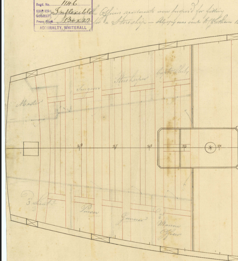
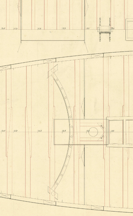
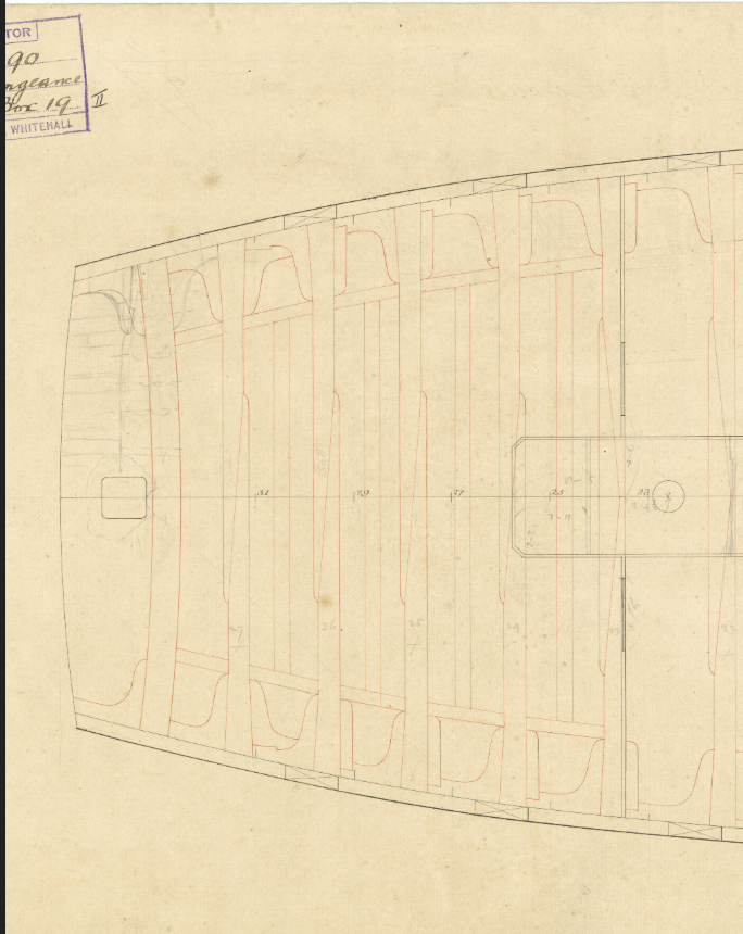
Good Evening Mark; I have done a bit of looking through the draughts on Wikimedia, and besides the Dorsetshire, there are plans of the Hampton Court and Weymouth? with similarly detailed deck plans. All of them show the knees abutting the carlings with rounded ends, not cut off square. See below a plan from Inflexible, which, although it is dated 1790, when she was converted to a store-ship, shows the deck beams from an earlier period. Doesn't show any knees, unfortunately; but the carlings are far enough from the side for the knees not to need shortening in any way. Following on from some of the comments above, here is the deck plan of the Stirling Castle of 1775, showing the improved sweep with rollers and other parts of the steering mechanism, which will be of interest, even if it is from a later period. Then there is the deck plan of Vengeance, 1774, showing just what you need. All the best, Mark P
-
Good Evening Siggi; I hope that Mark won't mind me answering for him, but if you are asking about what I think you are, this is a deck beam structure using half-beams; which is a fairly common method of fitting the deck beams in the after end of the deck. It allows for shorter beams to be used than are otherwise required. All the best, Mark P
-
Good Evening Matle; It is well worth reading; as it is subject to copyright, I cannot post it or a link here. I can say that there are many accounts in the literature of the 16th-early 17th centuries which describe sea fights, all in the context of firing the bow guns, then the broadside guns, then the stern-chasers, then perhaps the other broadside also, and then moving away to reload. This was a common tactic for all nations, commencing with a 'charge' towards the enemy, before firing the bow guns. There are multiple references to this kind of tactic by many contemporaries. The ultimate aim originally was to soften up the enemy ready for boarding; which gradually developed into standing off and battering each other with broadsides. Regarding the wheeled truck carriage, this is also discussed by Rodger in his article, with the view that the wheeled carriage was not developed as part of allowing for recoil, but more to allow the guns to be run out at the beginning of an engagement, and withdrawn inboard at the end of it. The idea of using the recoil was seemingly adopted much later than we might expect, part of the possible proof of this being noticeable increases in the sizes of gun crews in the first decades of the 17th century, with repeated running out being the main reason for this. All the best, Mark P
-
Thanks for your reply Matle; I do agree with you that it seems to be a rather daft idea to load outboard (in the Van de Velde sketch mentioned, a member of the gun's crew is sitting on the barrel outside the port) but according to the tactics of the period, the reloading was carried out away from the enemy, so while not being shot at. Nonetheless, it does seem rather inconceivable. Your mathematical workings are a welcome addition, and you are correct in that I did indeed ignore that, responding instead to the seeming intent of 'silly'. I will try to avoid such limited views henceforth. 🤐 The other points re broadside development had been discussed previously in the thread, and can only be settled in the mind of each reader, as there is no solid consensus either way. Rodger's article is interesting because it provides a lot of good reasons to believe in the development of full broadside fighting rather later than has been frequently stated in other works. I started this thread on the assumption that most modellers, and other readers on this site, will not be aware that there is much of a debate on this subject, lying as it does at a time in history before that which inspires the majority of models. If this thread succeeds in widening the debate slightly, that will be a beneficial outcome. The Vasa replica is a wonderful bit of film, which has been mentioned on here before, and I imagine that most people seeing it would be very glad not to be on the receiving end of cannon-fire. It obviously gives a solid and reliable basis for the mathematical calculations you show. All the best, and thanks for your contributions, Mark P
