Mark Pearse
-
Posts
836 -
Joined
-
Last visited
Content Type
Profiles
Forums
Gallery
Events
Everything posted by Mark Pearse
-
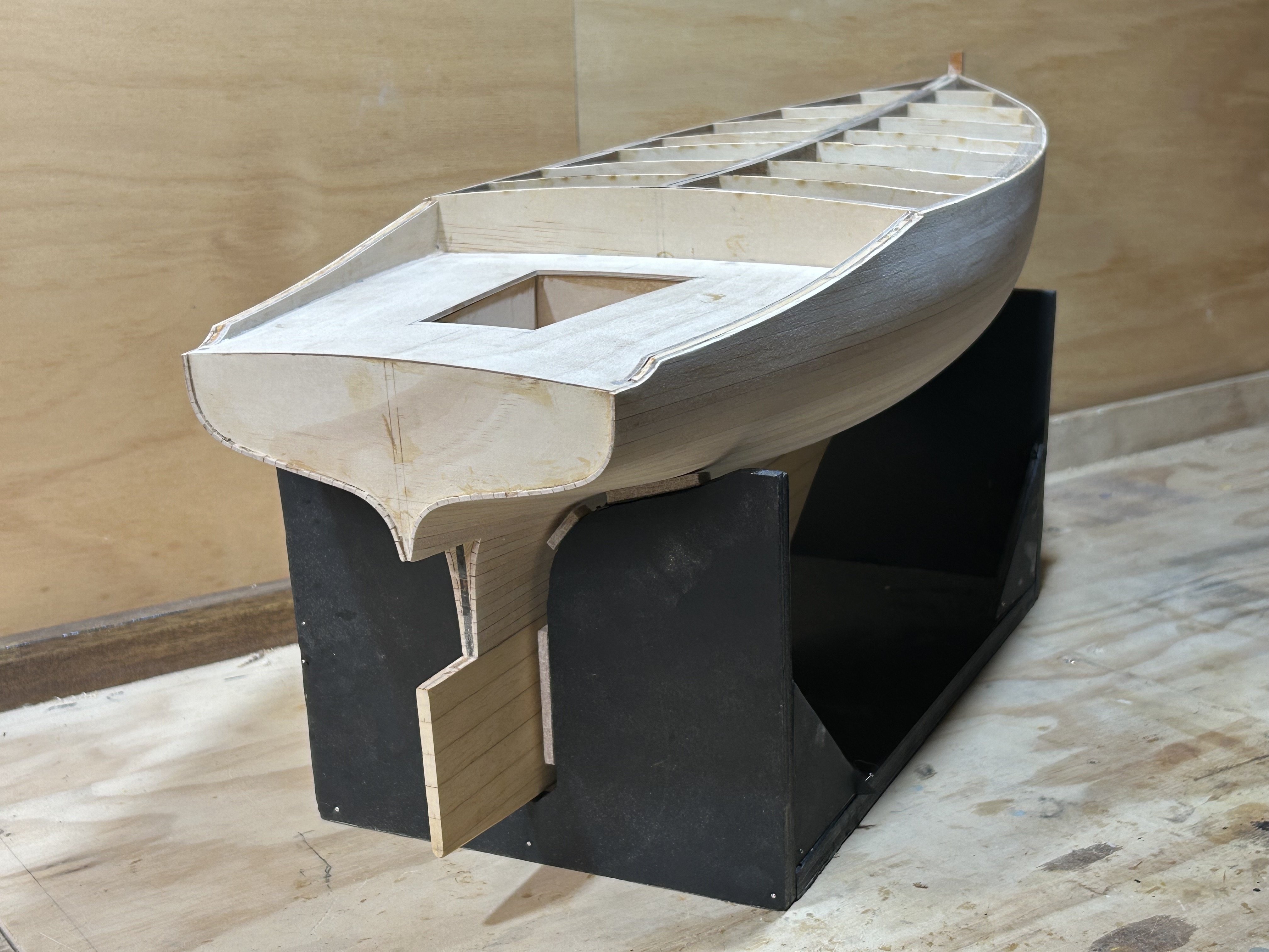
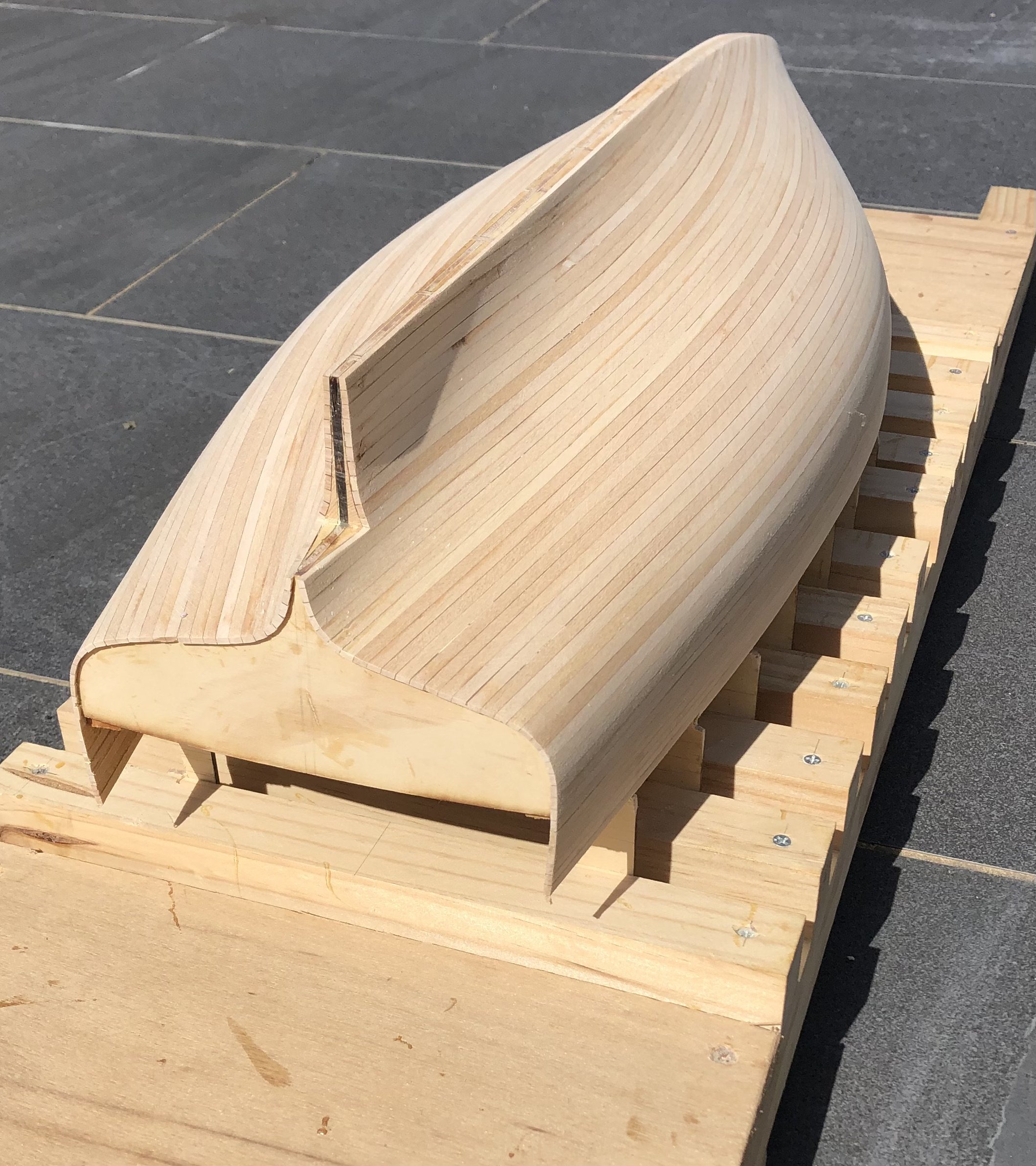
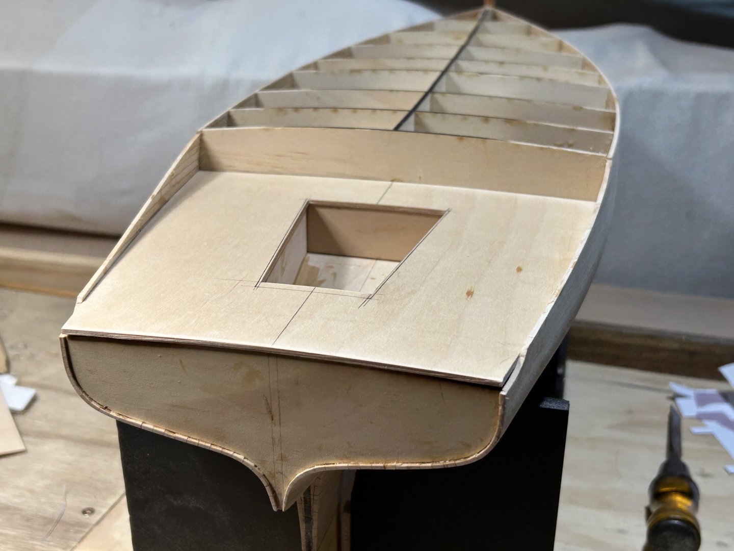
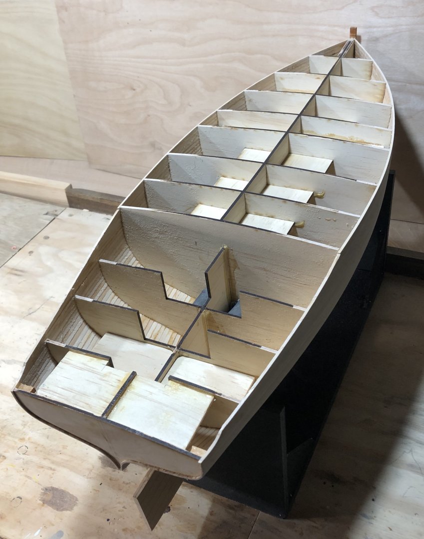
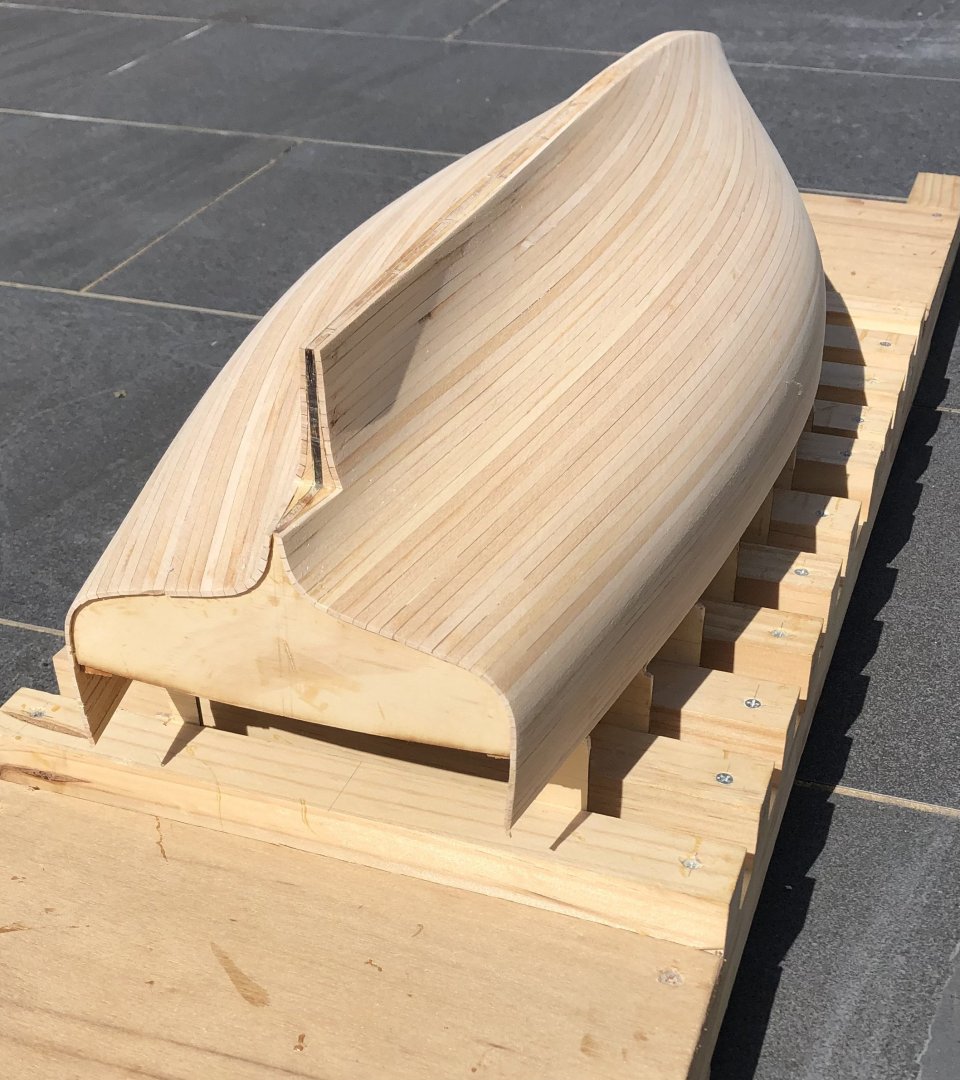
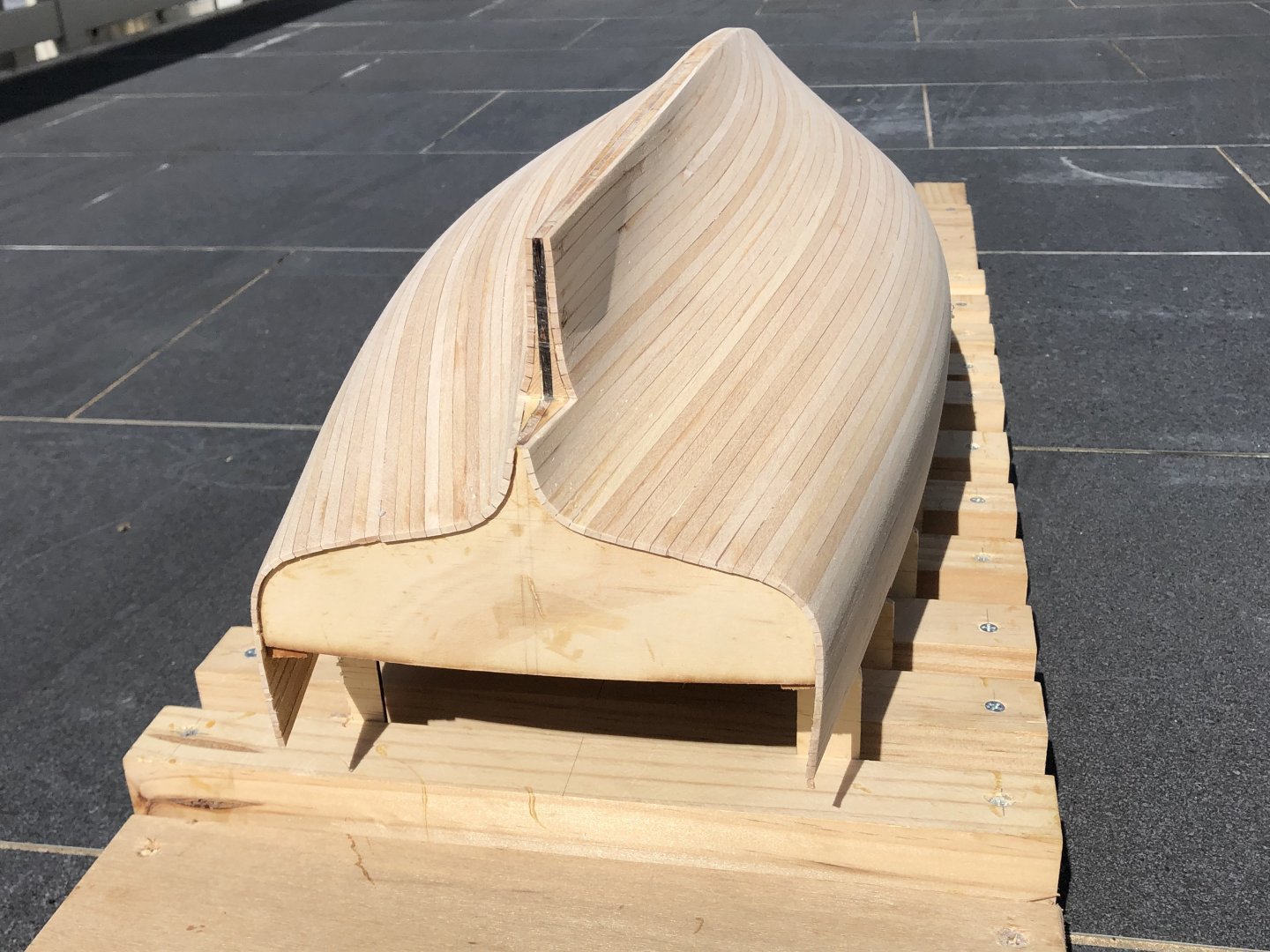
 The cockpit seat & scuppers area is now glued in place, & mitred at the transom. The side sections of hull were laminated to a scale thickness of about 80mm, approx 7mm actual. The width between the footwell & hull is divided by the seating backrest, which does more to keep water out of the cockpit on a windy day than it does to provide sumptuous & ergonomic seating. The width of the deck landings have been increased with strips of hardwood, Spotted Gum I think. I will use small screws to help the plywood deck to hold its camber while the glue goes off, so the screws can go into the hardwood rather than the edge of the ply. The mast sits on the 4th bulkhead back from the bow; the tripled strips are where the shroud chainplates sit. Although with a static model there's not a lot of load, it means I can have a leg on the back of the chainplates going down into the hardwood, & glued. Given it's not much work it's worth it for whatever additional strength it gives. I'm probably ready for the deck, & then probably the timber to infill& finish off the propeller cutaway. thanks,
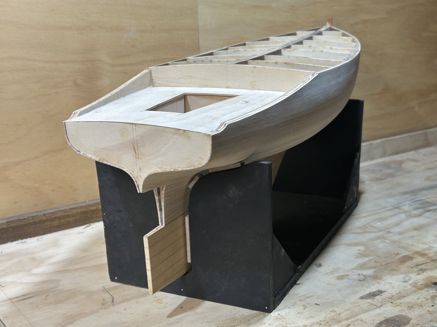

-
Hi Vaddoc, She's looking fantastic, very nice work on the finishing details. I think the vertical rod is the engine throttle control. The horizontal rod just contains it against the coaming, & possibly had some notches or something to hold in set positions. The small rod just behind the engine would be the gearstick, for putting the engine into gear or neutral, probably it was just a thrust gearbox - not real gears, you just push the lever forwards against a friction plate & the propeller starts turning & the thrust of the propeller keeps the friction plate engaged until you pull the lever aft & disengage it. On the rope steering, I am guessing the reason is so they can steer the while working in another part of the boat. If you do an internet search "Herreshoff rope steering", his small yacht design the Coquina was fully rope steering. A rope might also mean that the steering would hold a certain position, especially if there was a v cleat or horn cleat - tillers are great but when free, the boat will steer where it wants to go. The rope might give some ability to set it a bit one way or the other, as well as steer while tending to the catch in your lovely fish well.....
-
Hi Steven My only comment on the anchor is that the stock needs to be perpendicular to the curved hooking part, to encourage the hooked ends to bite into the sea floor. Apologies if you already were aware of this, I understand your drawing might have been just to get the proportion right. Noting that it would have been straightforward to make the stocks so they can be parallel to the hooked part when sitting against the ship's hull, & perpendicular when the anchor is deployed.
-
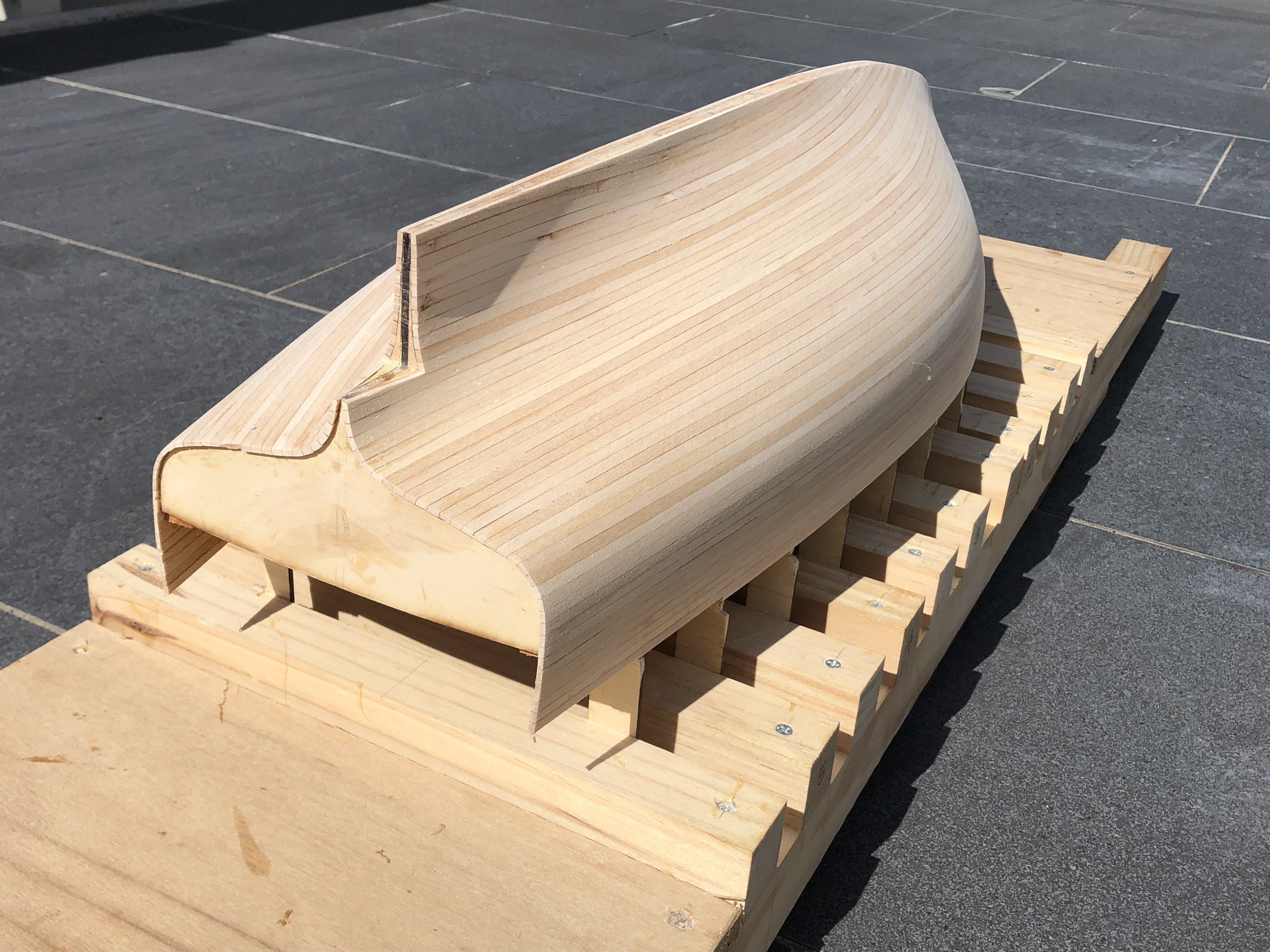
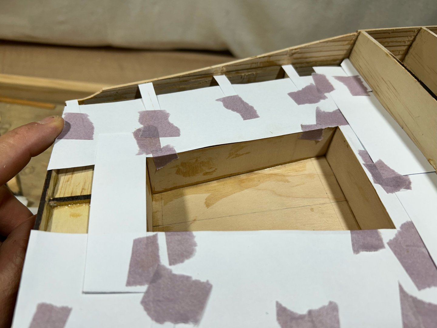
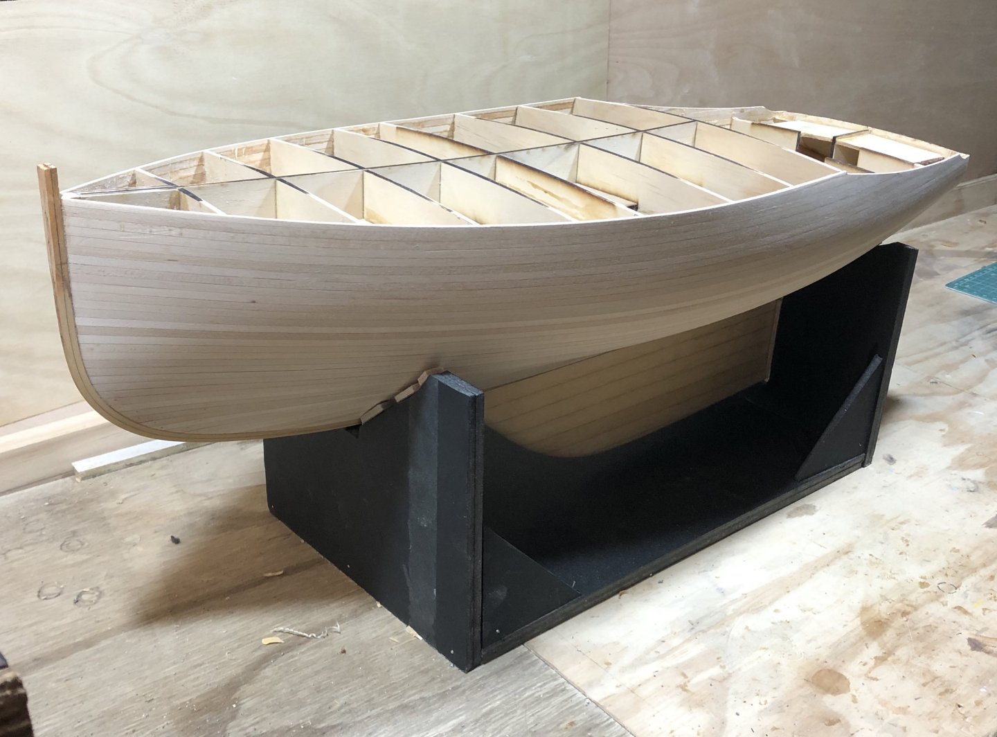
The basic forms of the cockpit area can be framed up in ply, & I'm using 2mm birch. The footwell was done but doing the deck & scuppers area in one required some joggle stick style paperwork as it's enclosed on 3 sides, & 2 of them aren't vertical. It looks unlikely in the photo, but actually it was easy to do accurately. I could slide a metal ruler below the paper to be able to press the tape down onto something at the right level without distorting it. And sitting loosely in place. In the photo it's sitting 2mm too high at the stern - it will mitre to the top of the transom & so sit down lower, as this boat has no timber trimming piece or fashion piece there to cover a join that could split later. The alignment at the sides (to the hull) isn't critical, the raking strips of hull above the ply will be built up to 6-7mm thick or about 70-85mm actual, which can sit on top of the plywood. Unlike many remarkable builds on this forum, I'm not concerning myself with the inner parts of the vessel being true the actual boat.
-
Hi Roel, Thank you for taking part....& I agree they are a funny hull shape. A design that is definitely trying to get the most boat from the least timber - noting that the original was designed in 1933 & I think that's the depression or soon after. I think people then also just tried harder to get more from less - 7.3m wasn't a small boat in those days, but it certainly is now.
-
Druxey - thank you & a good suggestion, I didn't consider that. Keith, thanks also - the effort to set up interlocking frames was an interesting exercise & enforced accuracy. It also worked well with the available drawings on the boat, just the full sized lines - it's a quirk that the boats built to the design are not the same, they do vary but most keep to the concept of the underwater lines from the original design. John, thanks - I knew I'd heard that phrase before...now I just need 50,000 'volunteers' to assist on the build.
-
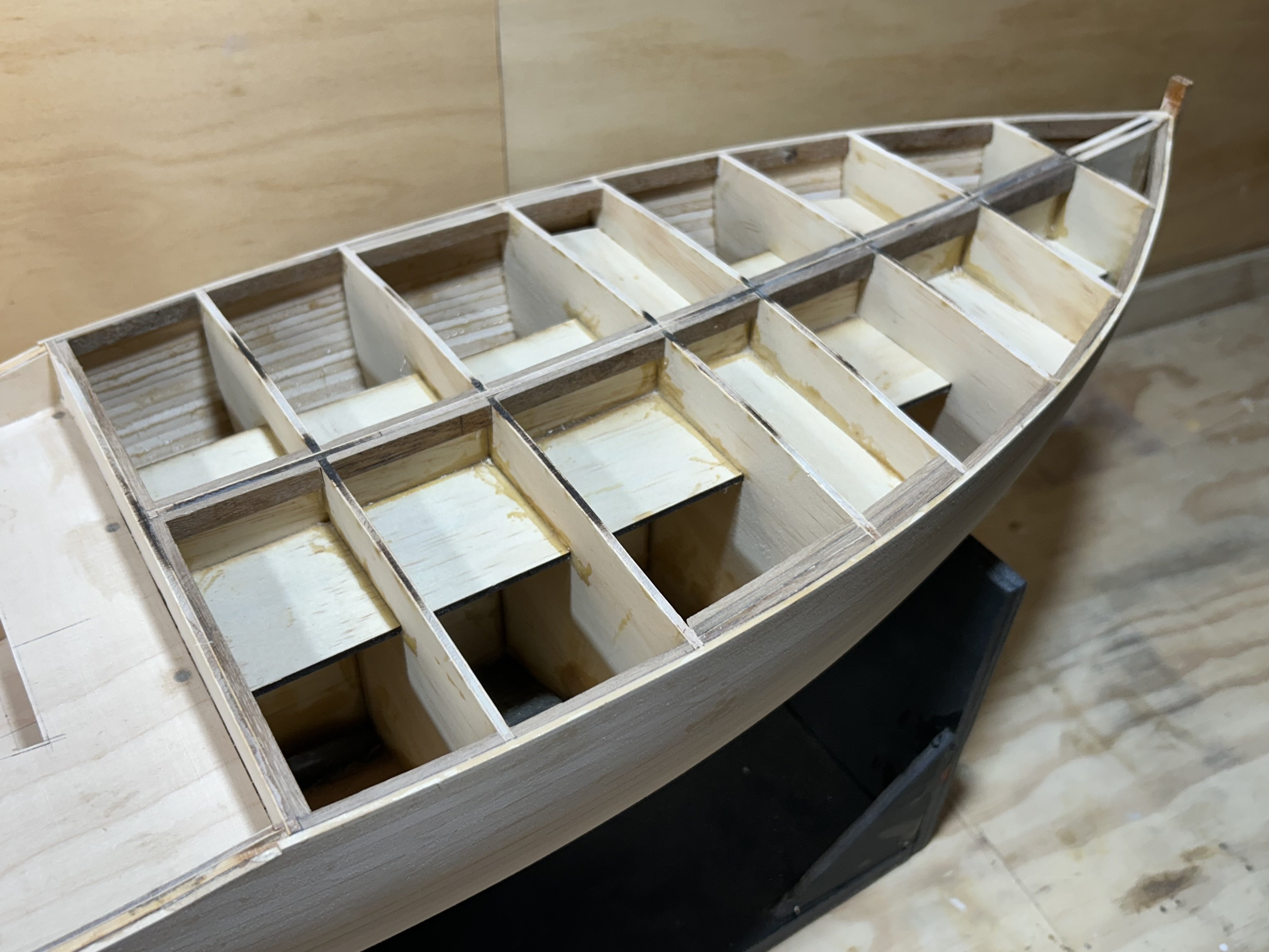
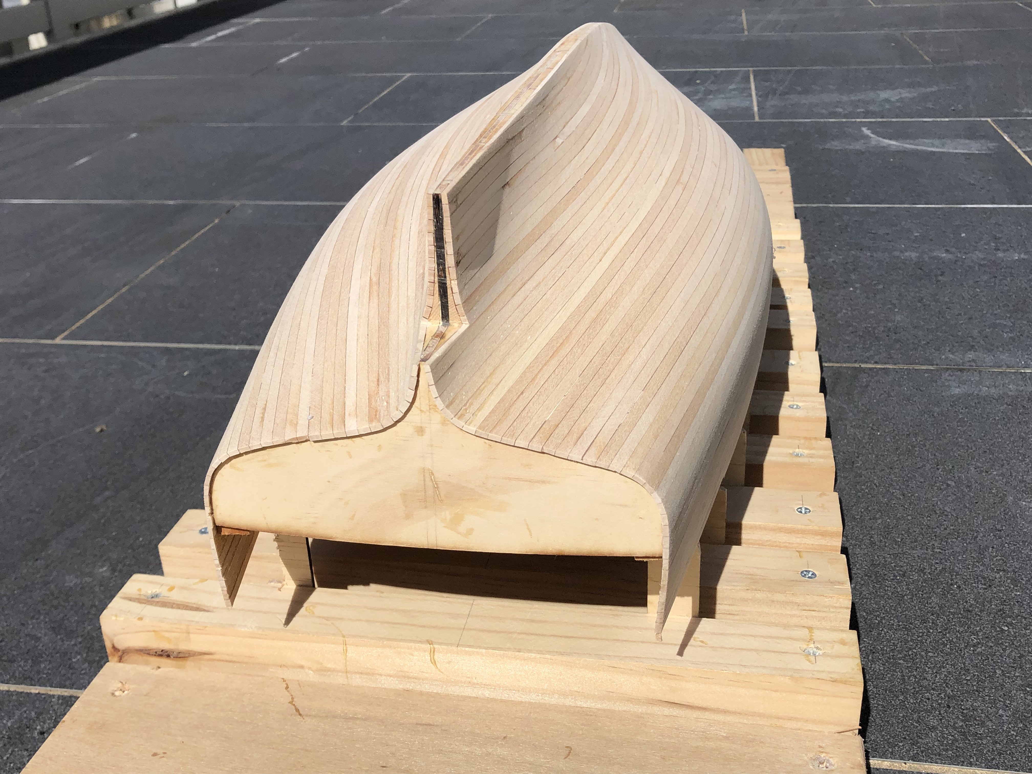
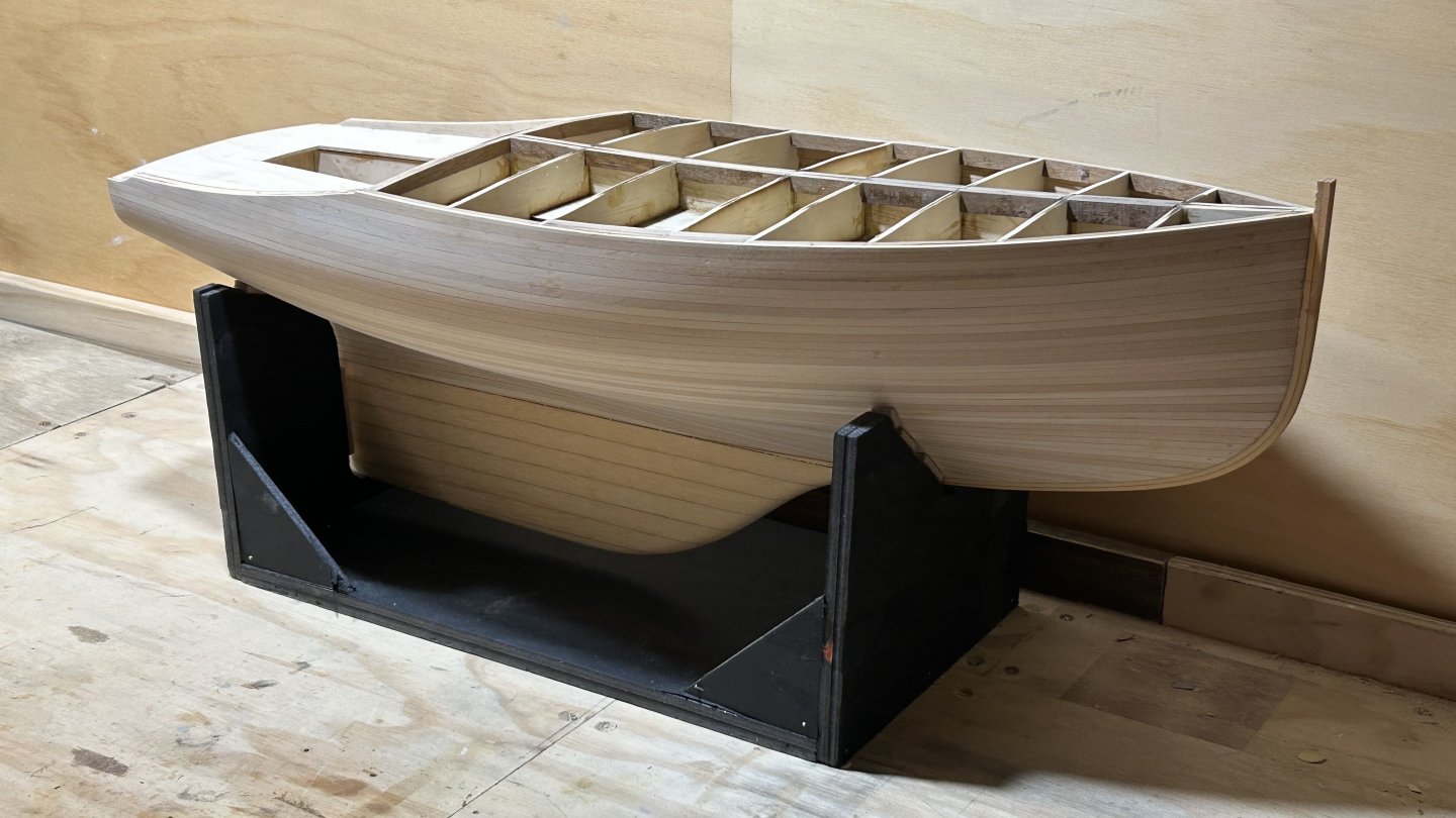
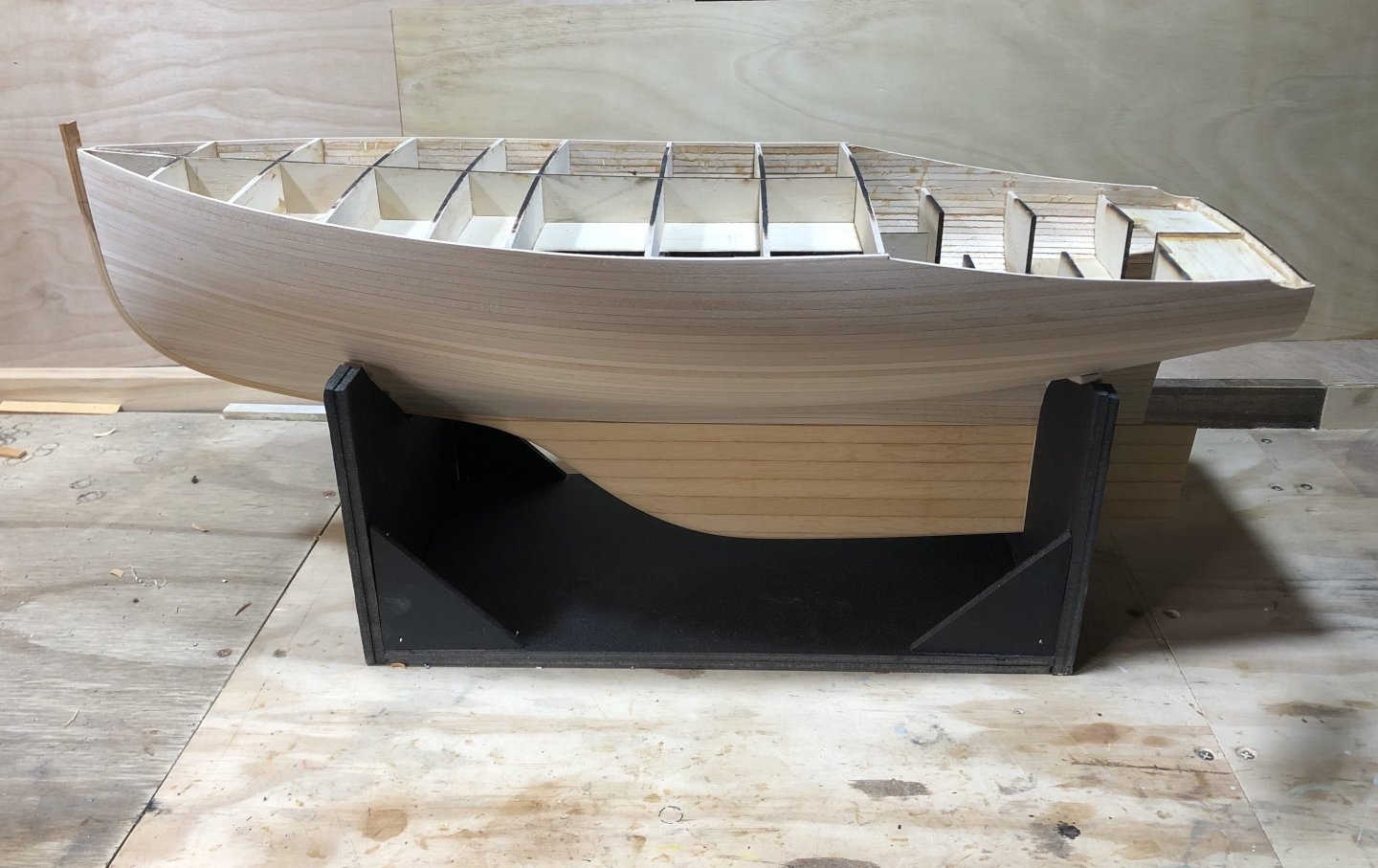
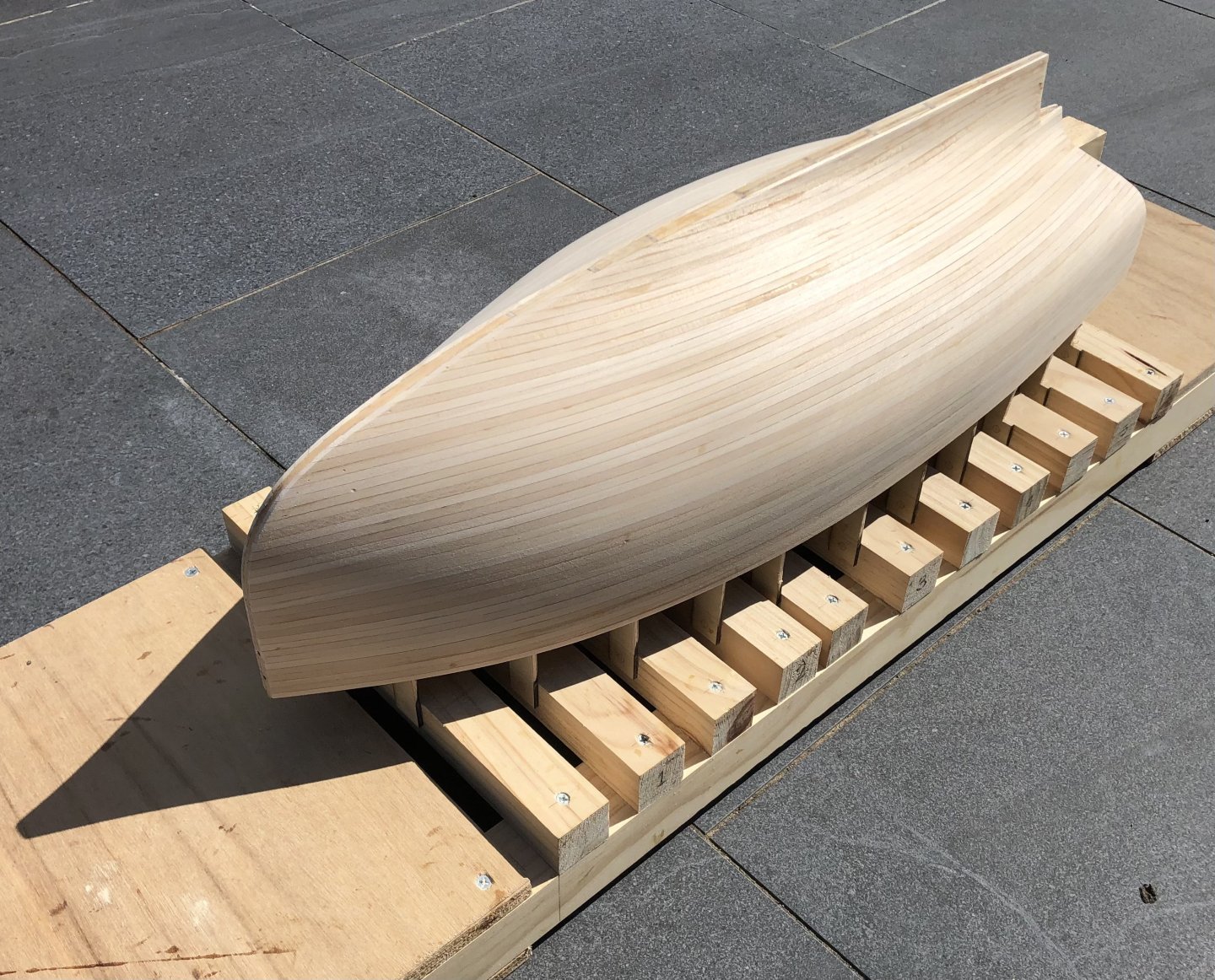
It's exciting to have a stage where there's a great leap forwards in what the model looks like. This was one of those weekends, spending time taking pleasure in the unfolding of the model. Turning the model right way up & trimming the aft hull sections makes a big difference, she's looking a lot more like a yacht now. And not just like a yacht - the beamy but well proportioned lines are starting to show. The support is from some free foamcore cardboard, it was easy to make but I'm not sure it's going to last the distance. Stout boats, definitely not a racehorse, with just a hint of of tumblehome.... The large volume of the hulls is really evident here. I have added some scrap lead inside the hull, I think it feels better if they are slightly heavy & it's probably safer for the model. Those 4 pieces, found on a building site, are probably about 500g or 1lb. Cut into 4 pieces & glued in place. Hopefully the time spent working out the pre-cut plywood frames will make the next stages simpler. It can be quite tricky to measure - for example - the height of a cockpit sole off the hull. Next I'll start laying the cockpit plywood, & have a think about the rigging - if there needs to be anything done now while access in the hull is still possible, such as backing for the chainplates. One more thing, on the related 28' design for Maluka: following her good result in the recent Fastnet, there's an article on her in the June Classic Boat mag. She's still in the UK & her owner will be cruising the north east coast of the UK the next few weeks.
-
that handle method for the wheel is a good one, & I hope it separates well for you
- 110 replies
-
- 3
-

-
- Paddlewheeler
- Ballarat
- (and 3 more)
-
You're making it appear easy. And that's a nice hammer.
-
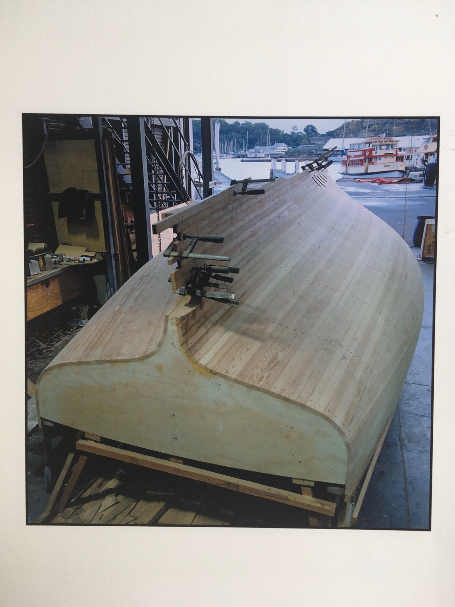
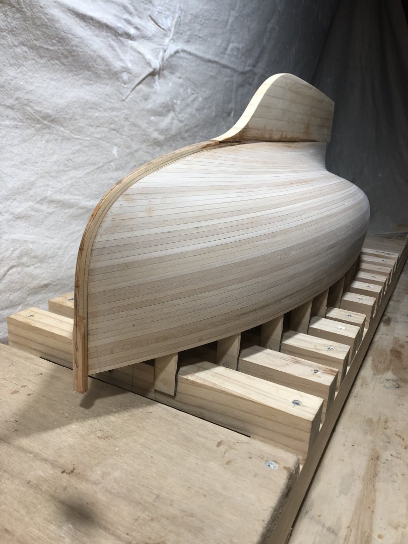
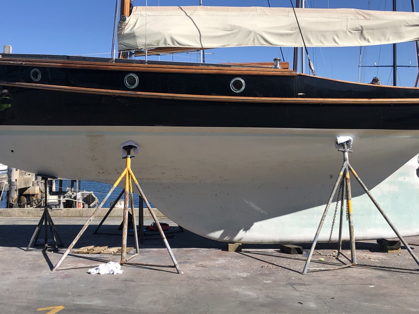
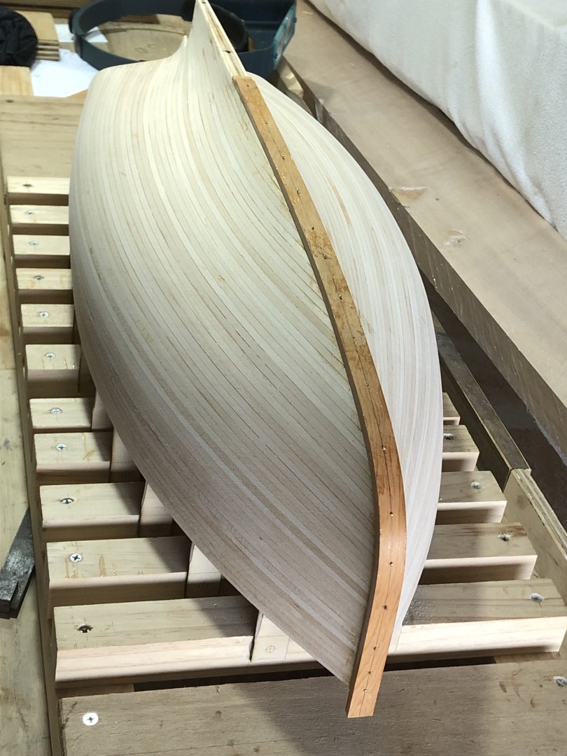
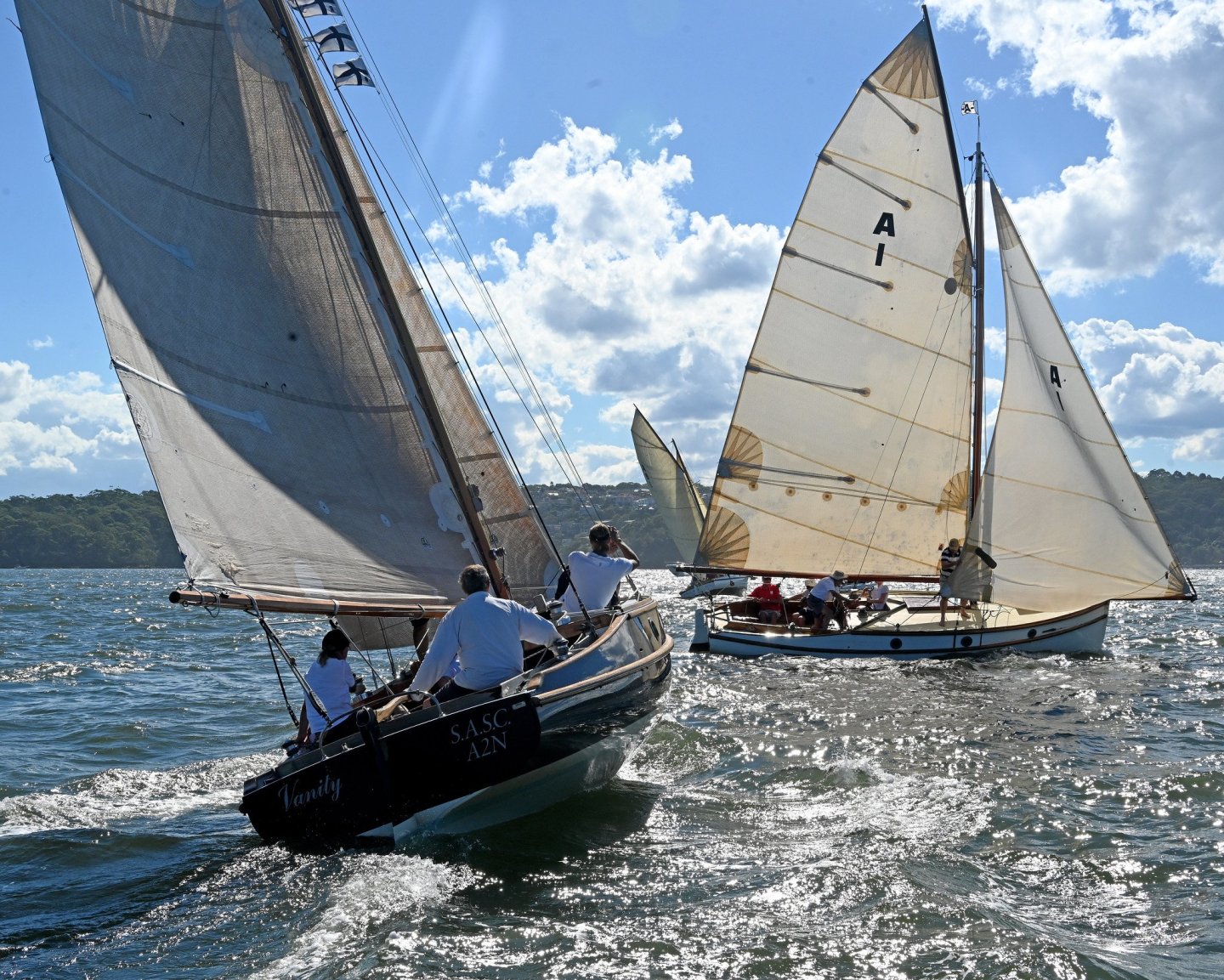
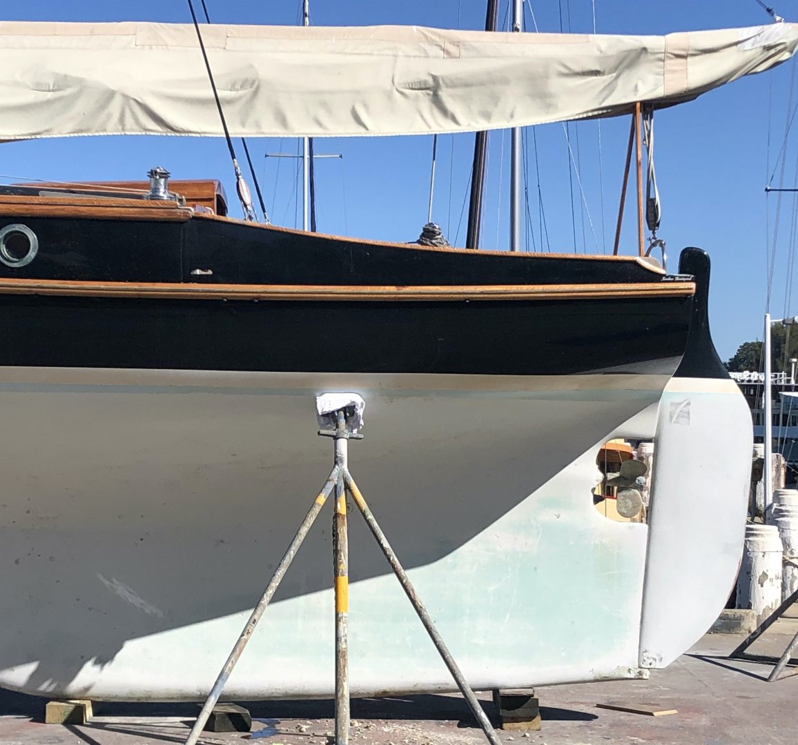
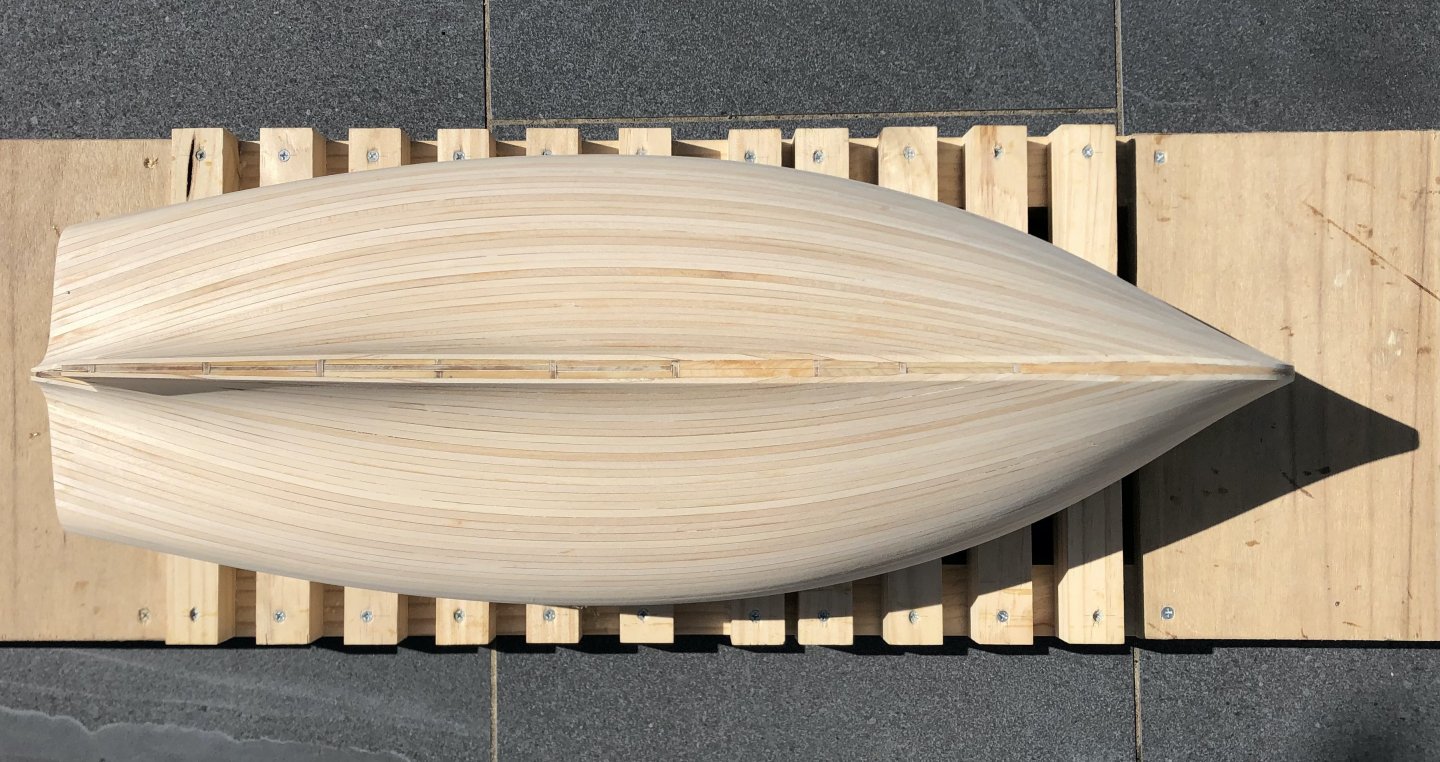
Some photos showing the hull with outer stem & keel glued on. Also some initial shaping of the stem piece. Interesting how the parallel planks give some optical illusions, as the ones closest to the keel have their rocker upside down. Some photos are almost unusable from this effect. The aft part of the hull & keel are smoothly faired. The front section of the keel meets the hull at a crease rather than a faired shape. You can see this in the hull photo from Vanity, below. At this stage I don't know for sure if I will need to use any filler or not, in the keel/hull area.
-
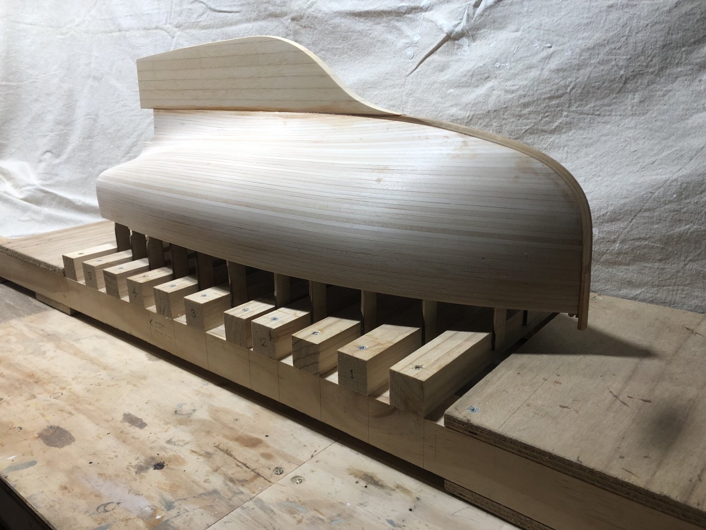
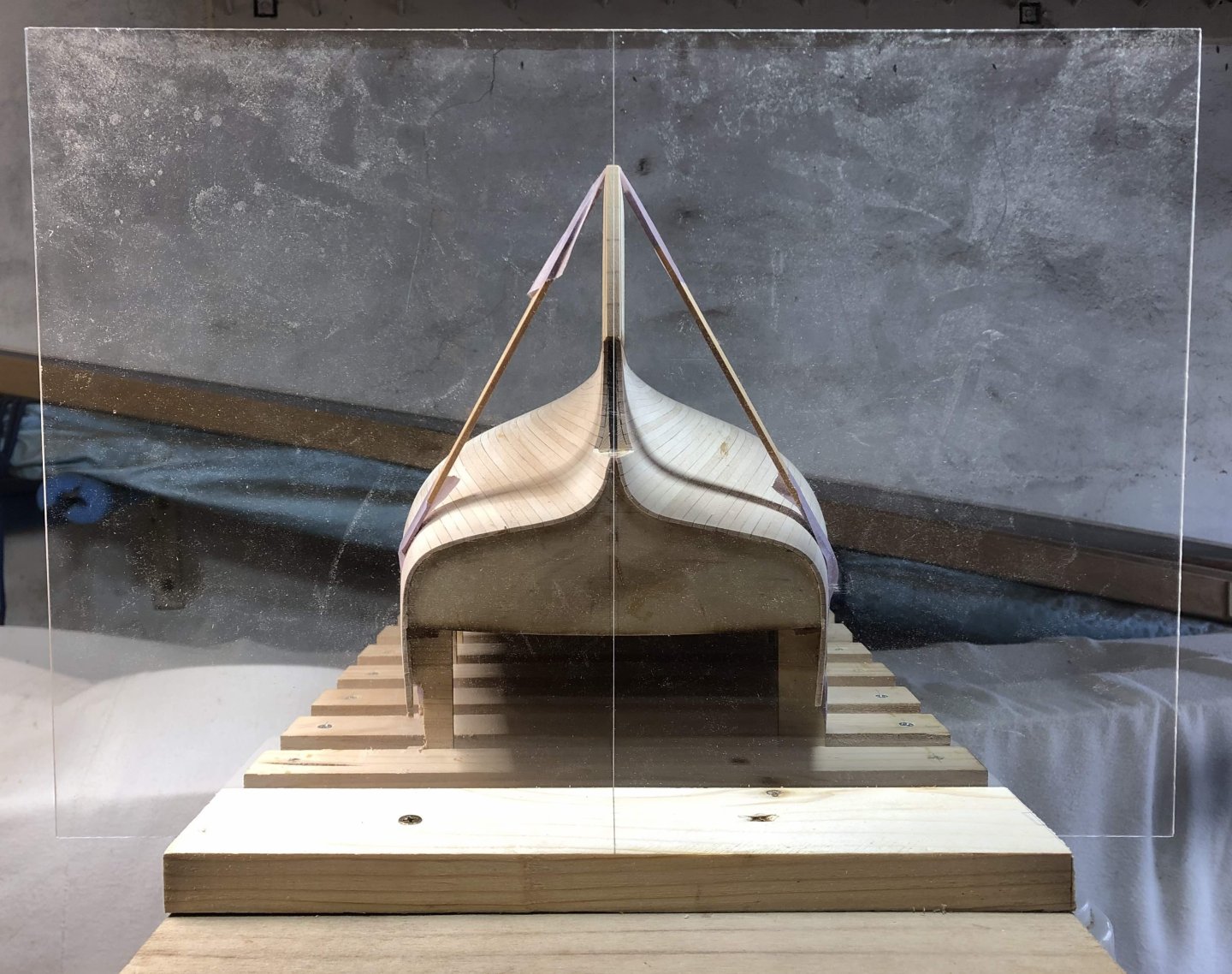
Nothing like a wet weekend (& end of the summer racing season) to free up some time. I sanded the keel down to an approximate shape, glued the outer stem on & gave it some initial shaping, & glued the keel on. More pictures later but this shows the way I'm ensuring the keel is plumb. It's a piece of clear acrylic sheet with a line square to the base scribed on to it, then fixed to the building base. Two light strips of timber with masking tape stay the keel, I'll check it in a few hours, & by that time the epoxy will be stiff but not beyond movement, should there be an issue. The following steps will be slowly & carefully fairing these to each other. Then the infill piece for the propeller cutaway. It's possible some filling will be required where the keel meets the hull, but we'll see. thanks for the interest
-
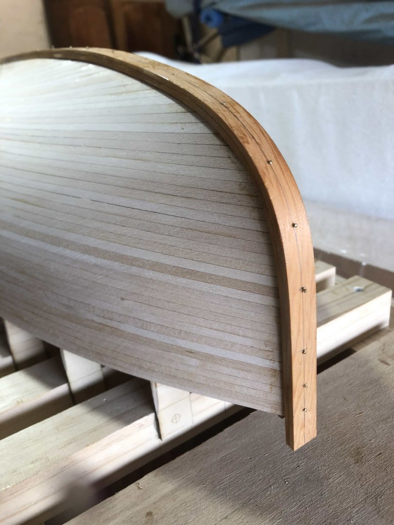
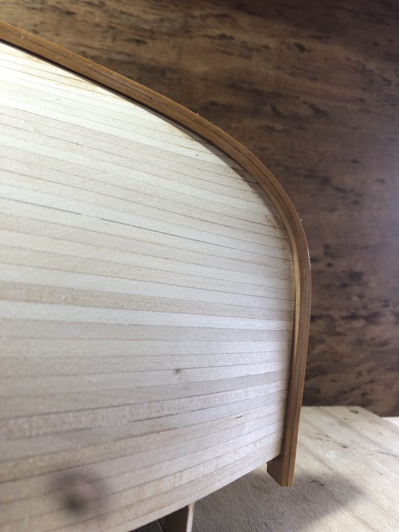
I started the outer stem & keel piece, that goes from the deck at the bow around to the keel. I decided to glue laminate it in one piece, partly because - as with the glued planks replicating strip planking - this is more akin to the way the actual yacht was constructed, as a timber / epoxy composite construction. I had some sheets of Sapele from something & even the 1.75mm (maybe 1/16th) thick wasn't happy doing the curve, with heating. I had some 2.5 thick strips of Huon Pine, & they were happy to do it, with a bit of heat from the hot air gun. I'd rather a harder timber, but oil based enamel paint is quite tough. I came across some tiny fine brass nails that I had bought & didn't use on a model, & decided to try using them to ensure the laminating is a close fit to the hull shape. Partly because the timber needs a finished thickness of 5mm, & with 2 @ 2.5mm there wasn't much adjustment possible. Anyway, it looks to have worked well, & hopefully hasn't been glued to the hull... I left about 1mm of nail sticking out, so I can pull them out. It worked nicely: Except for 2 (where a little more oomf was need to hold the timber in), the nail heads are left projecting a little to aid removal: Here's where you can see how well this worked - no gaps! Helped by the general pliability of Huon. thanks
-
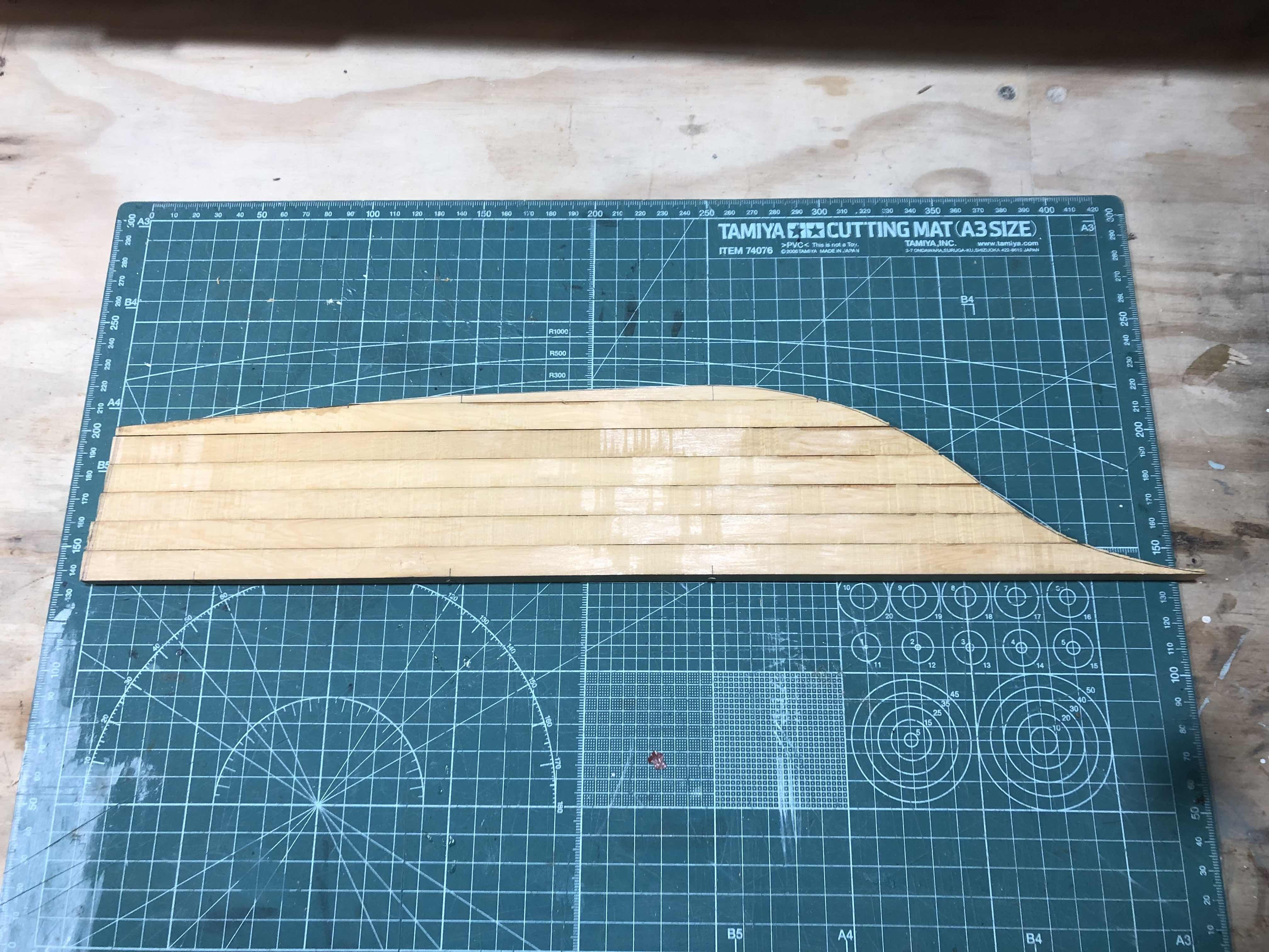
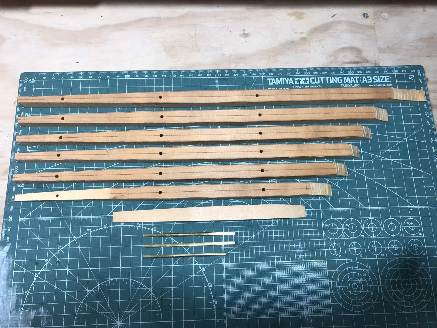
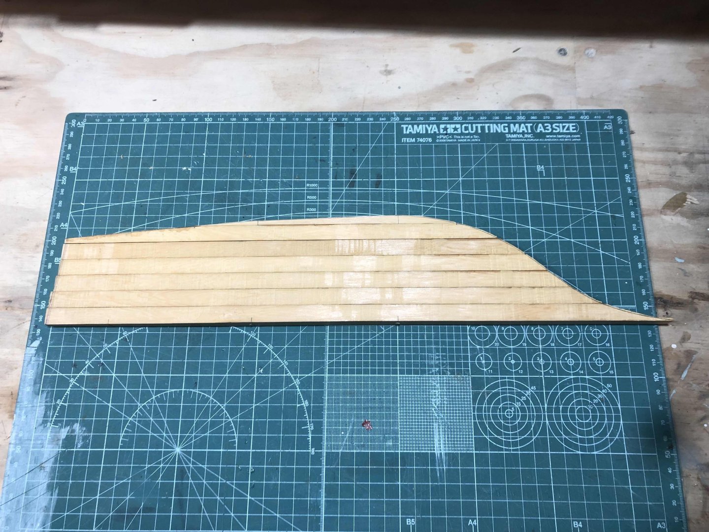
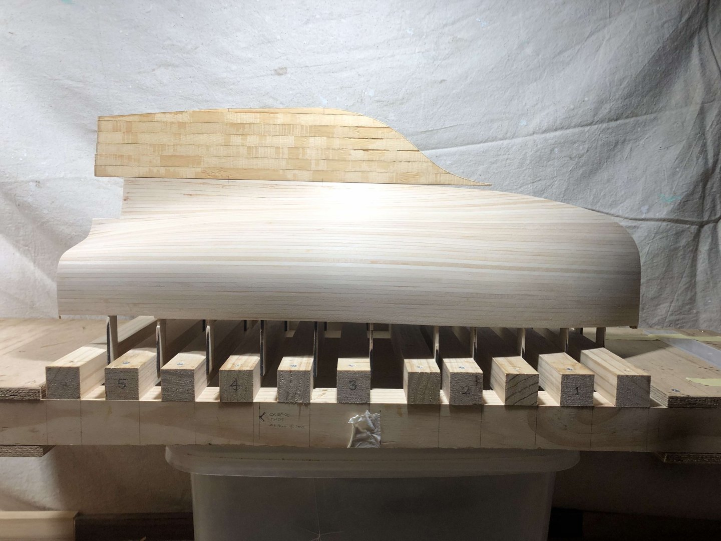
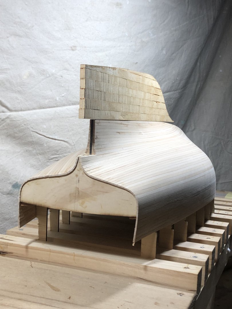
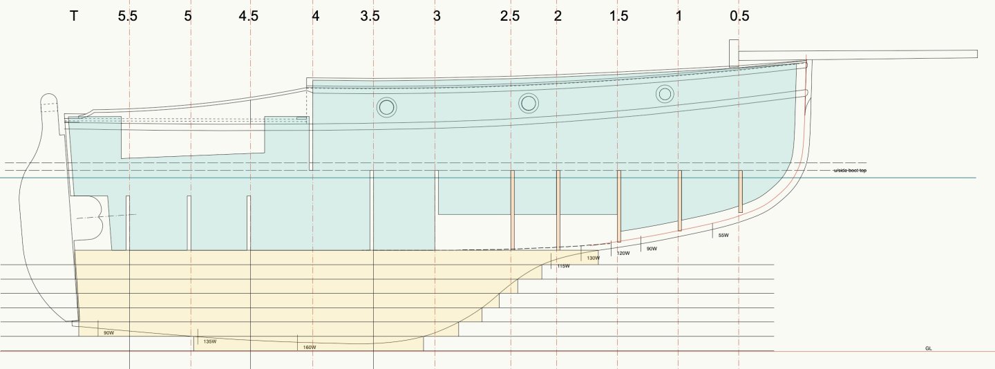
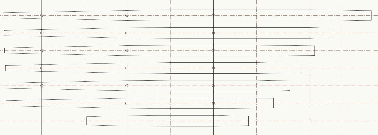
I've started on the keel. The shape is not complex, so it can be modelled pretty easily. For stability & strength I decided to make it from horizontal strips of timber, dowelled with brass. The timber is a nice straight-grained piece of Huon Pine. The keel is not a difficult shape: it fairs with the hull, but essentially it appears to be even from there down to the bottom of the keel. This is the keel side on. The yellow bands will be done in strips of timber. The strips, in plan: The timber pieces cut to shape, plus the 1/8th brass rod: Stacked & trimmed, & sitting on the hull. It doesn't look quite right, but it will. The hull has more sanding to get it down to the right size, I have left that to assist get the fairing with the keel right. thanks all
-
Hi Steven, I hope you don't mind my adding to the discussion, but I don't agree that this is an error - if the shrouds were on the leeward side then they won't have a lot of load on them. A helmsman could intentionally sail an angle to de-load a shroud so it can be worked on.
-
Hi Steven The weathering you did with the timber decking & elsewhere really looks great, it's very credible.
-
Hi John, She looks very good in the photos, but they don't do this model justice... I was at the museum Friday - the Walter Reeks book launch - & dropped over to see if you were in. Saw the model Meteor though, it's exquisite.
-
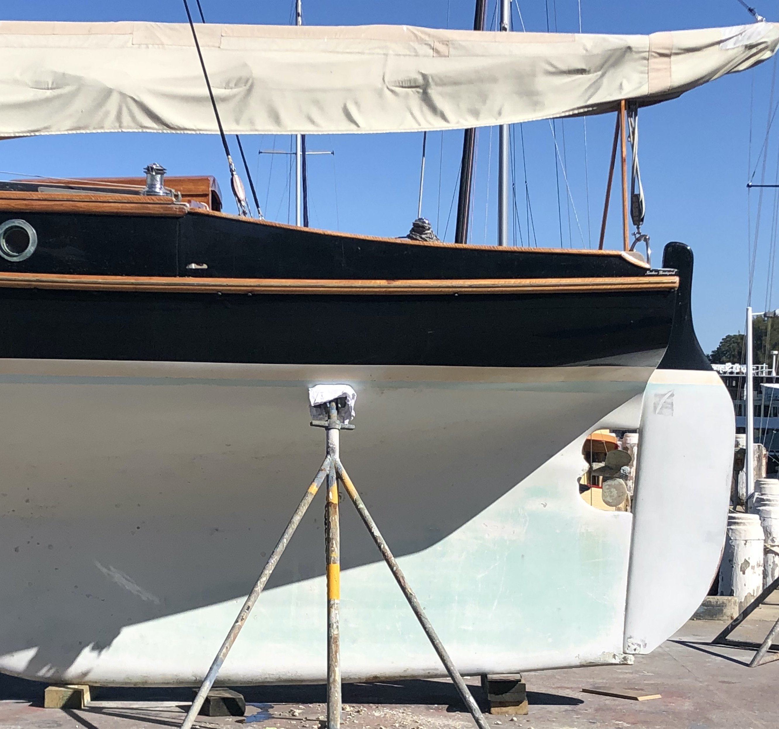
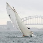
thank you all one more shot of the boat being copied, from the stern, crossing behind Ranger, the 1933 original boat
-
Yes, a lot of fun & what a nice boat. Sort of a large verandah with a paddlewheel. And it floats.
- 110 replies
-
- 3
-
-
- Paddlewheeler
- Ballarat
- (and 3 more)
-
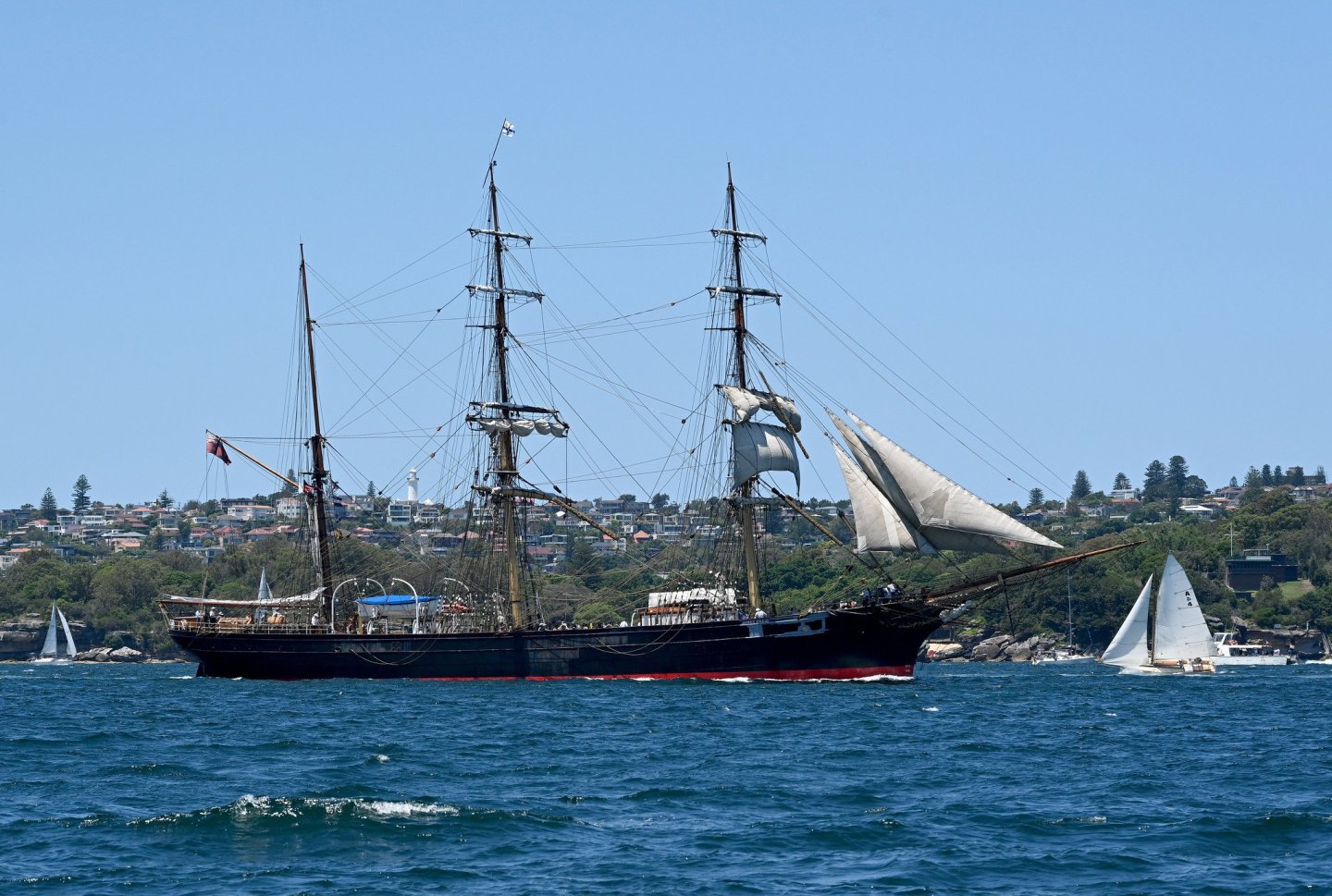
Hi Steve Good to hear from you. Yes, I think Cliff had a good eye. I hope your new home is working out well. (south coast..?) Hi Micha, Thank you, & thanks for reading the log. Re your oped-for next build: have you asked the people building them if they will send you lines drawings? They might do it. One more photo, it's the James Craig & the Ranger Cherub, bowsprit to bowsprit....Sydney Harbour a couple of years ago.
-
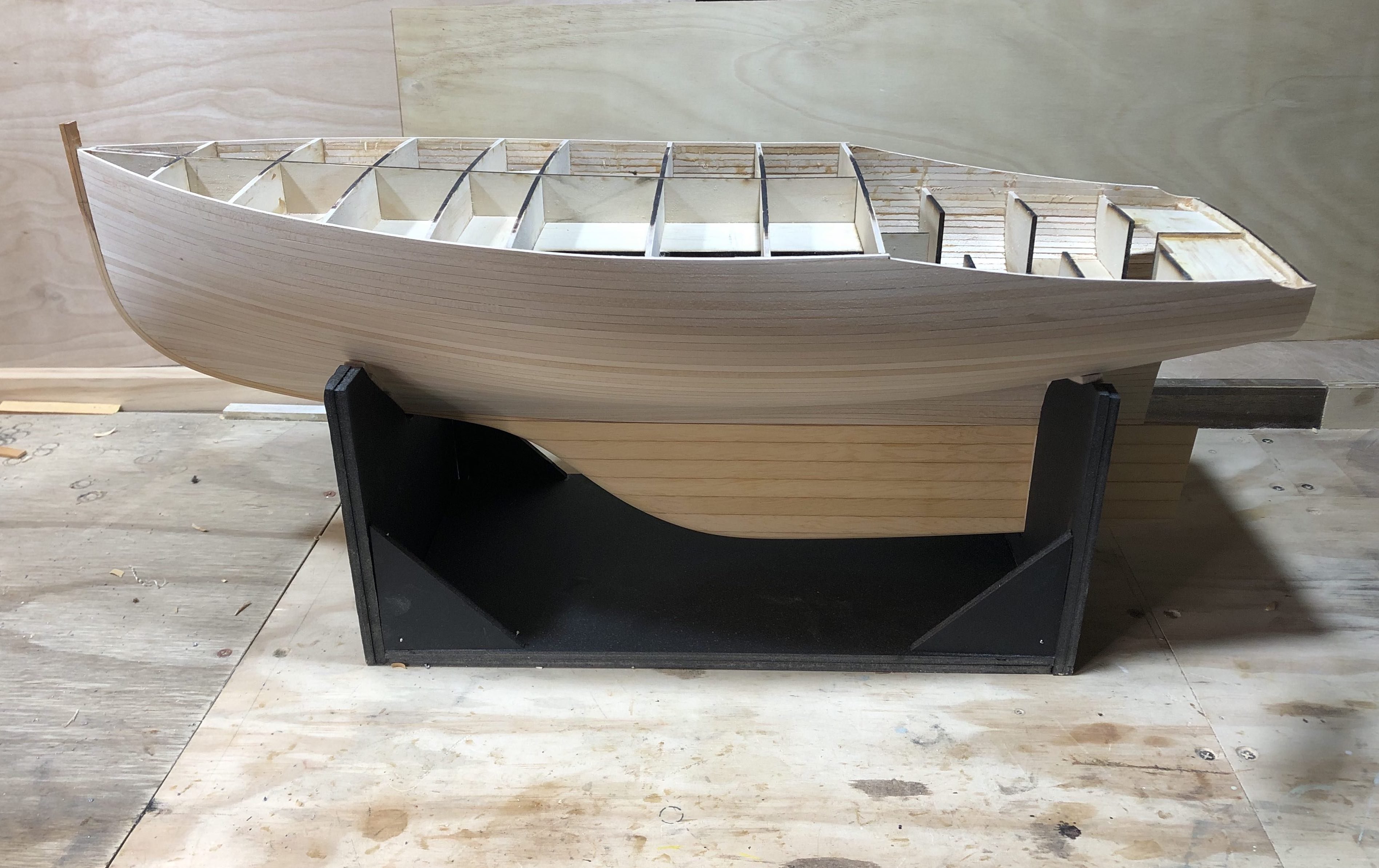
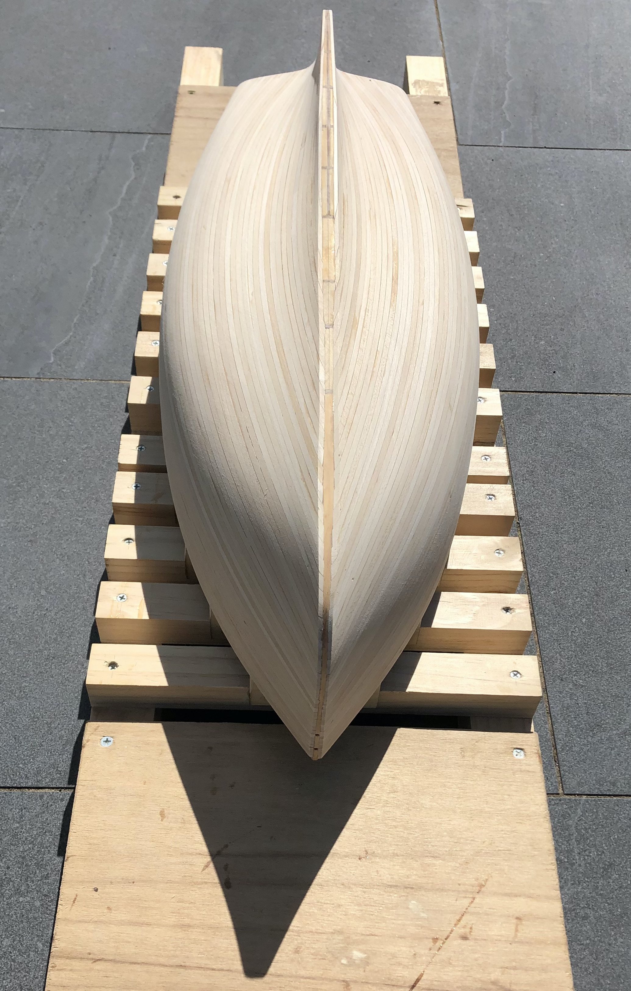
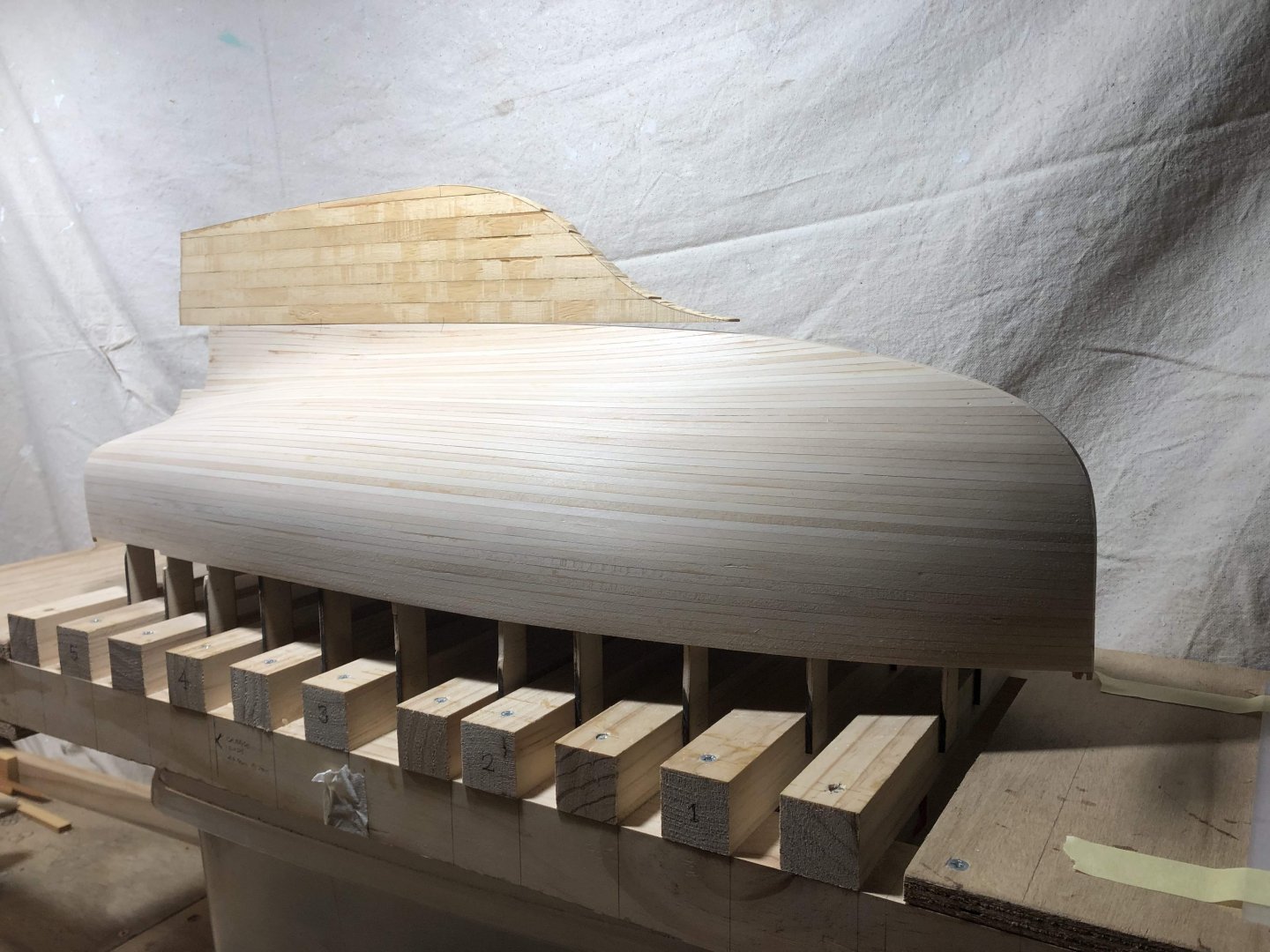
The planking is finished & I've spent a few hours sanding. This planking method (strip planking at scale) was visually messy, so it's very nice to see the hull lines start to become more visible. Although the nature of strip planks (being parallel sided), the planking lines throw the optics of the shape off a bit, as the line of the planks towards the keel don't bear much relation to the hull shape....the planking just follows the ones above with no tapering. The stern photos show the excess hull near the transom - that planking needs to be cut away - as the hull has the sweep down from the upper deck to the height of the transom. Photo below shows that gently curved line of that transition. I'll do a bit more sanding & then start on the keel & outer stem pieces. Also the infill piece that will turn the square cutaway at the stern into the curved propeller cutaway. They are a fat boat..... plus this for comparison: thanks


-
They certainly are. Looking excellent Vaddoc.
-
Hi Vaddoc Perhaps matt finish below the waterline? Antifoul paint is usually matt, & if the hull is still moving it shows inconsistencies less. I used a matt acrylic below the waterline (one model only) & the results were good.
-
Hi Vaddoc, good progress. And your daughter's boat is lovely, she will remember the experience of making something with her dad. I know it's painful subject, but is Beech timber more inclined to change size with changing humidity? I think Phil's advice to seal the timber is good, it should significantly slow down humidity changes of the timber.
-
Hi Steven, I went to a talk on the sailing of the Duyfken late 15C ship, they noted that the person on the steerage can get thrown across the boat. My thoughts are that your stance looks good, but perhaps a stance more braced...wider stance perhaps? Just a thought