.JPG.ca33079f5815b861e67b9c2cccd37982.JPG)

Blue Ensign
-
Posts
4,564 -
Joined
-
Last visited
Content Type
Profiles
Forums
Gallery
Events
Everything posted by Blue Ensign
-
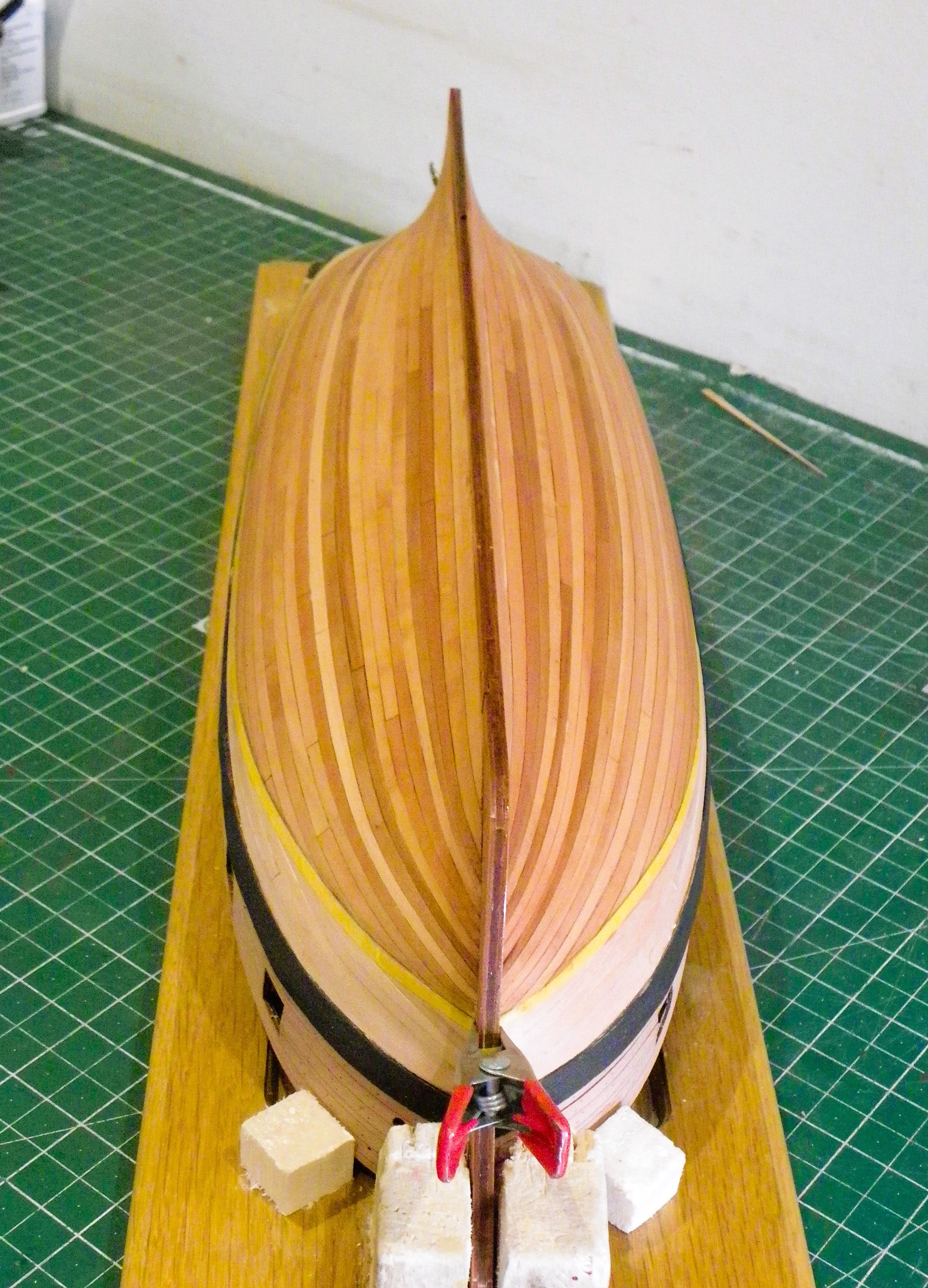
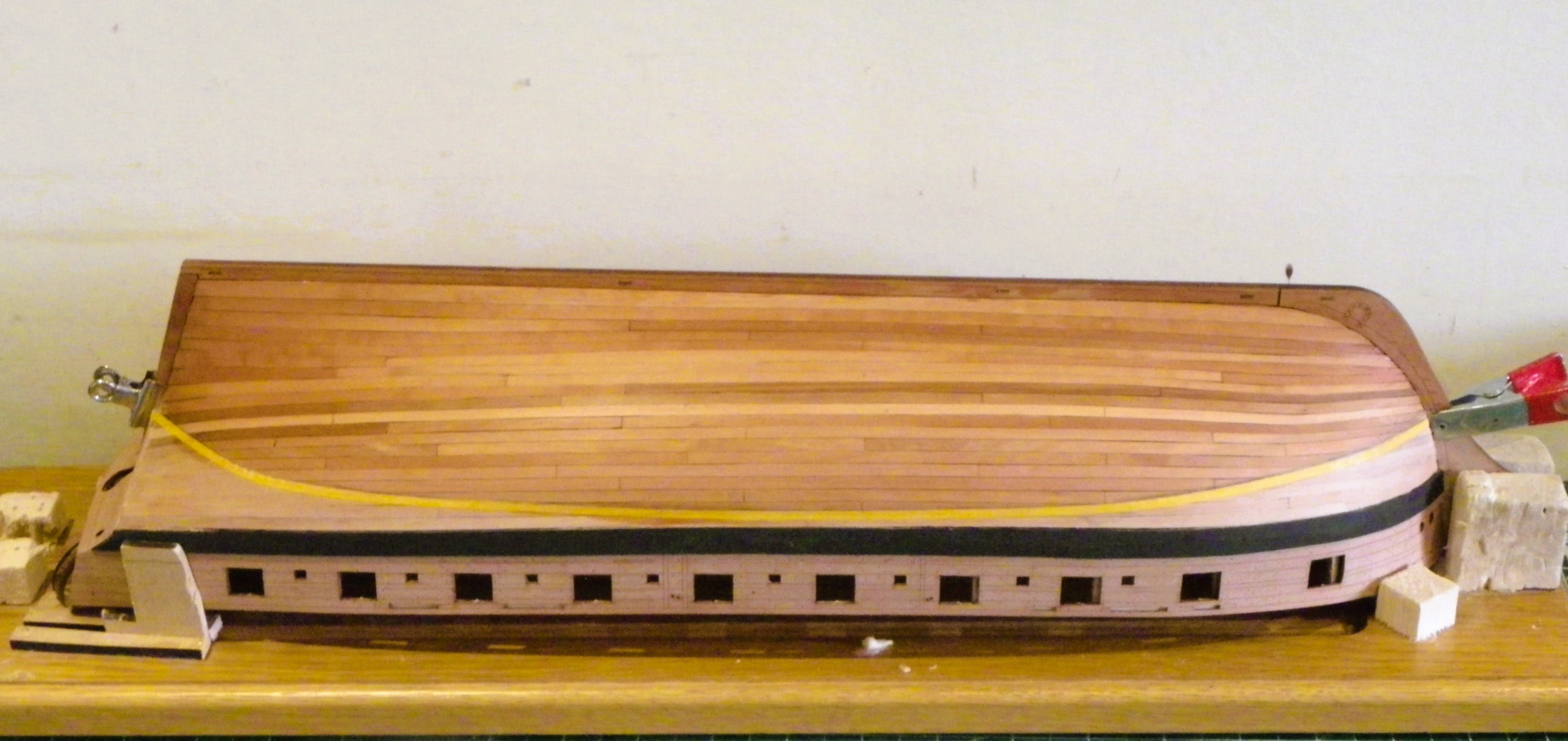
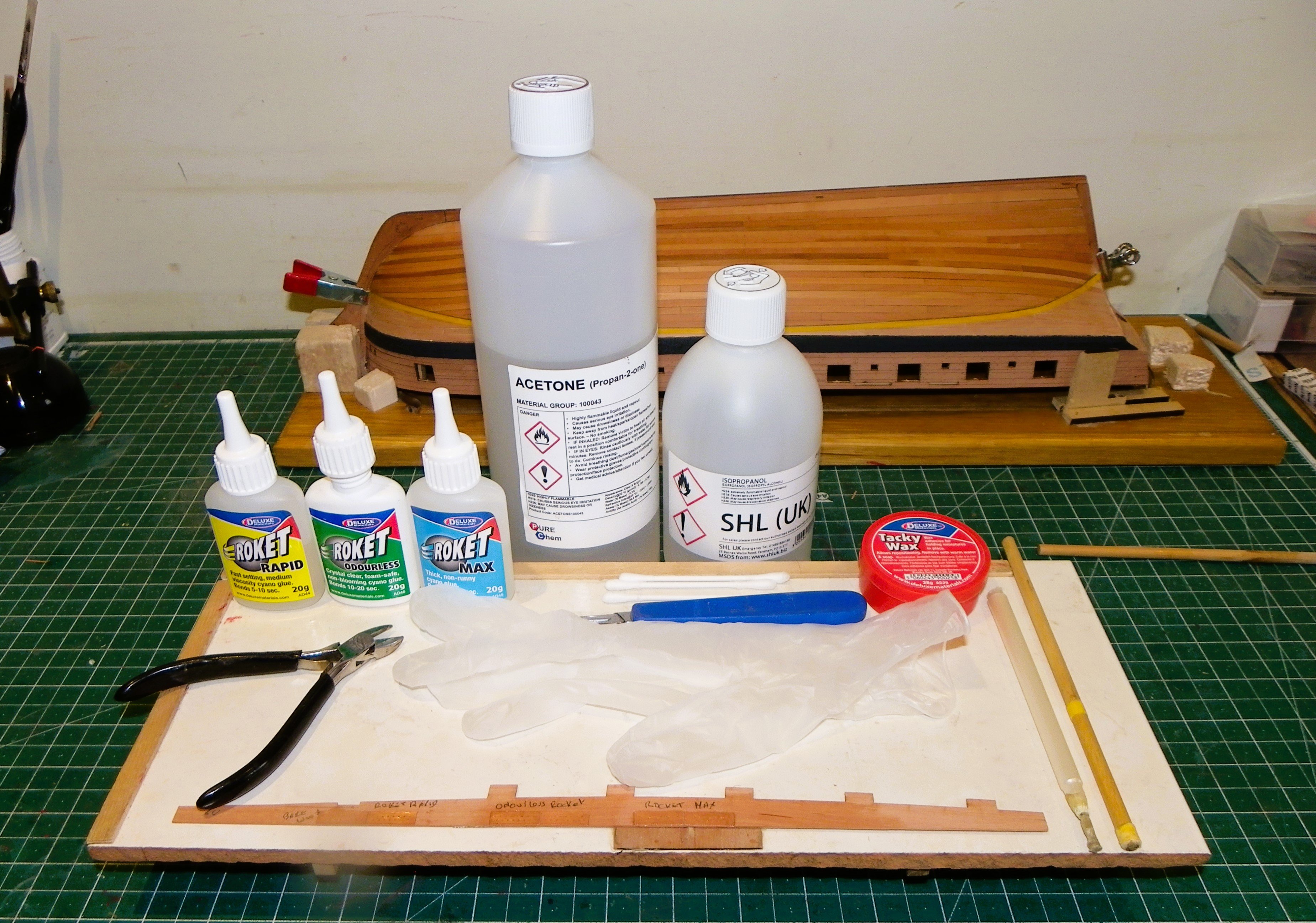
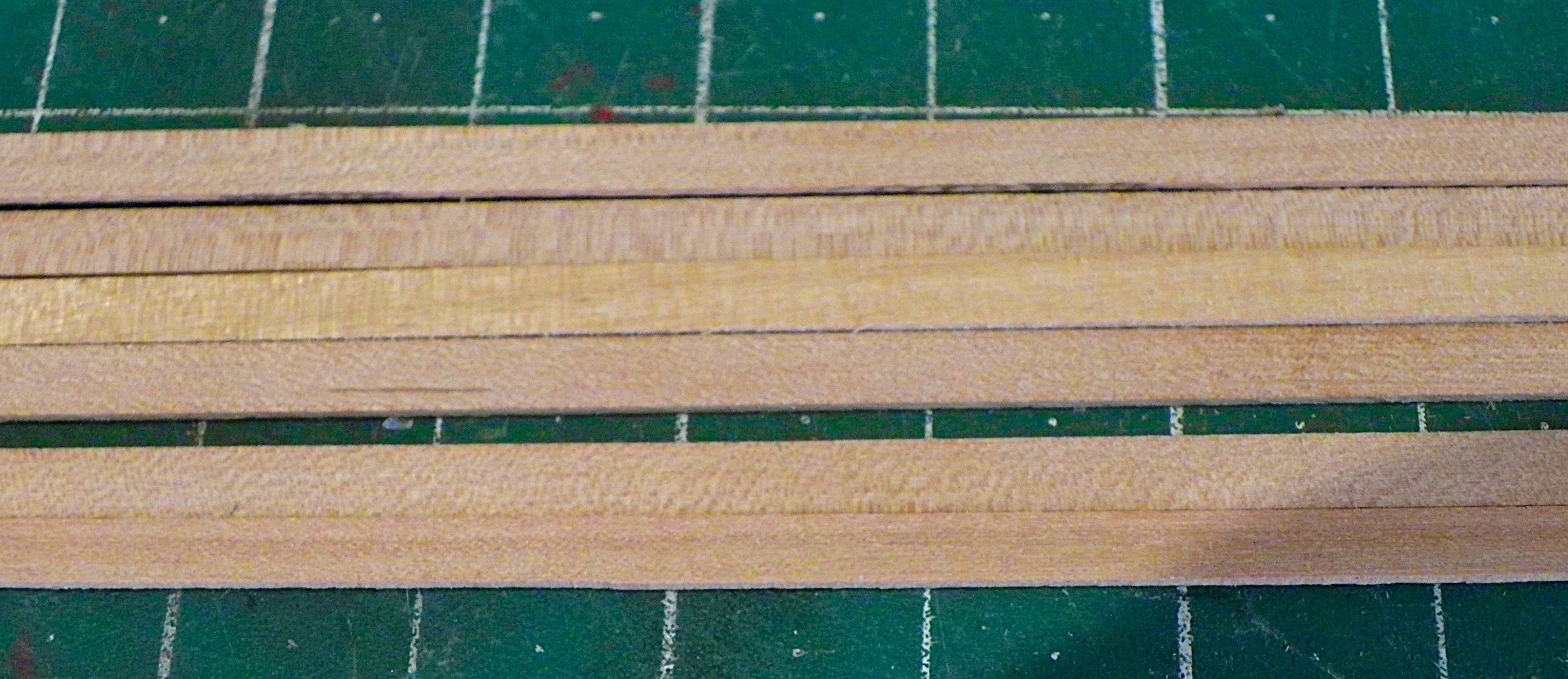
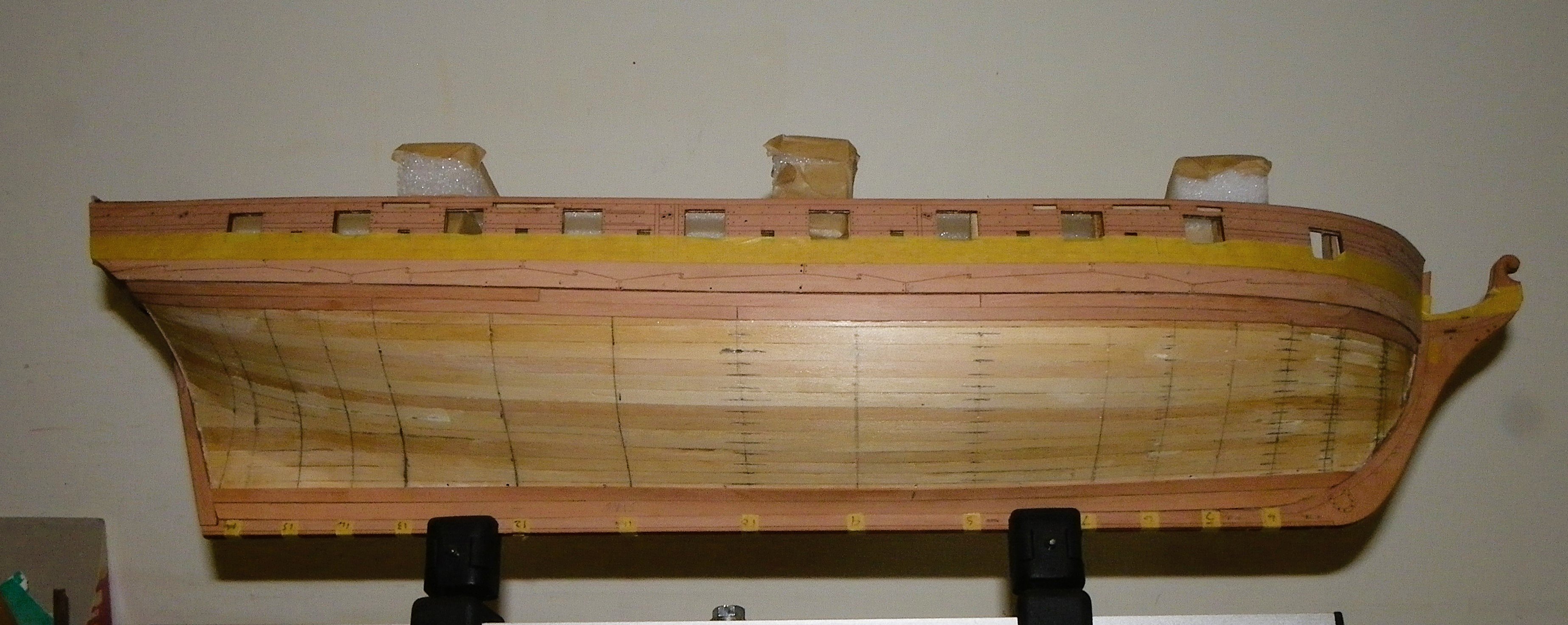
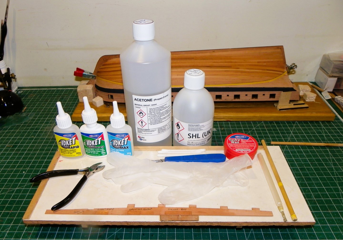
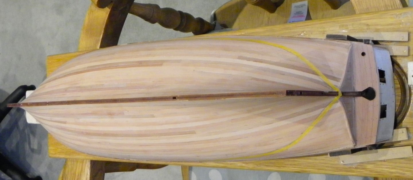
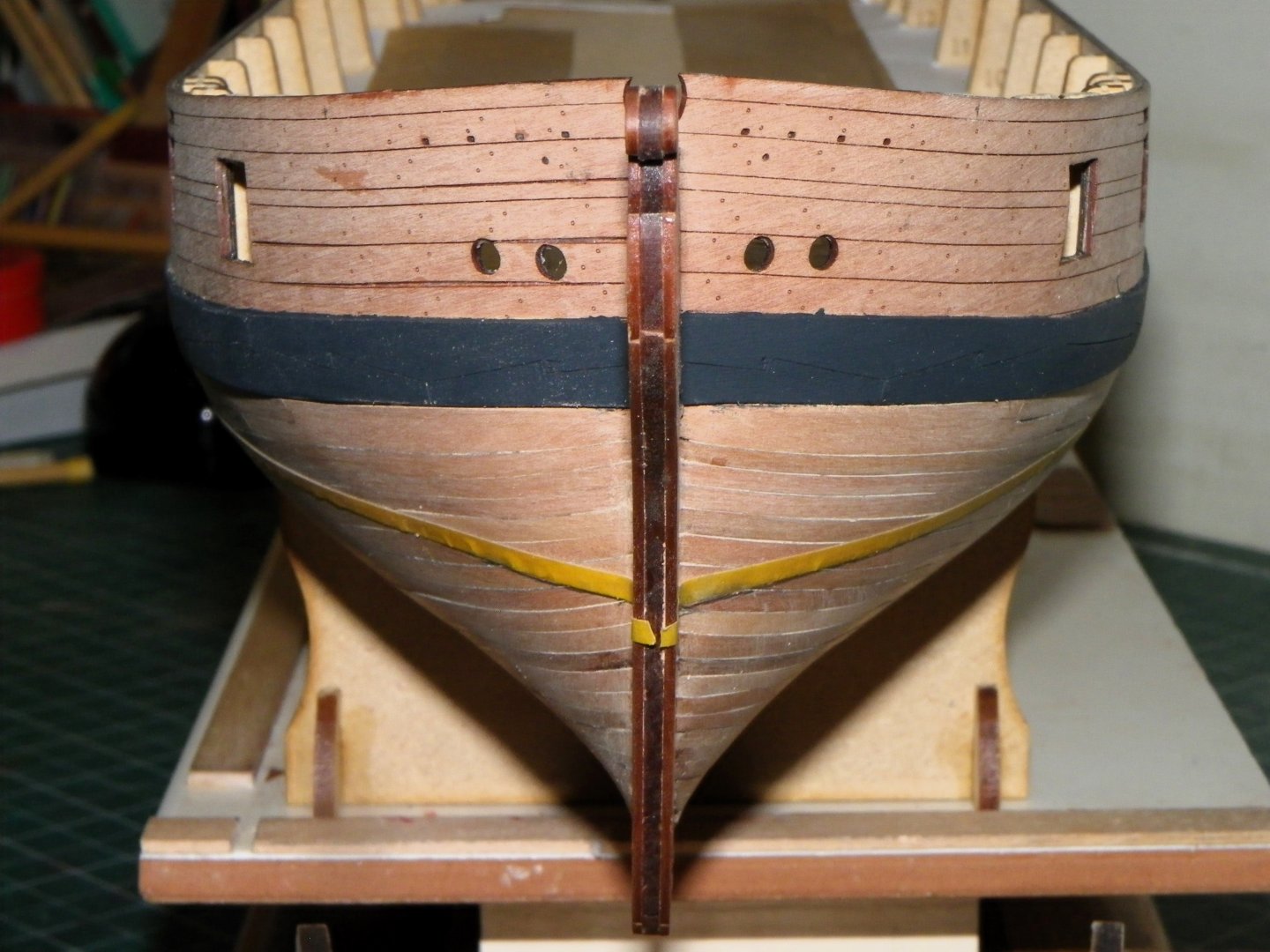
 Thank you Mark, there are a lot of repetitive and tedious tasks in ship modelling, tying ratlines, rigging guns, fitting deadeyes, and indeed coppering. I don't mind, I'm in no hurry. I want the build to last a while so I'm not tempted by the next offering to beguile me from the fertile mind of Mr Watton.😉 Post 30 Coppering Before I begin, I have given the hull an application of w-o-p which should provide a better contact with the glue. 0152 0157 0153 0154 Use of Poly surely brings out the planking, but as a purely varnished hull it wouldn’t do for me. I don’t like the striped effect of differently toned planks randomly applied, as can be seen here on the lower hull. Apart from aesthetics the effect is out of scale. I used all the colour matched planks which fortunately covered above the waterline, but there were insufficient matching planks for a full bare hull. With Harpy, only six Pearwood lengths were unusable for my purposes, but the odd few defects will always get through. 0203 I am not a fan of vertically grained or mottled strips, but they can be used beneath copper or a painted hull. In larger projects such as Sphinx and Indefatigable where my intention from the outset was for varnished hulls, I replaced all the Pear strip with milled timber from Hobbymill E.U. an excellent supplier of quality timber. With coppering preparation is everything to assist a smooth operation. I have assembled my application kit. 0161 Acetone for cleaning off ca marks. Isopropanol for cleaning plates. Disposable vinyl gloves. Pick-up tool and burnishing stick. Tacky Wax for picking up plates. Scalpel and cutters. I am now conducting tests on various cryanolates to see which suits me best. I would prefer not to have to use the standard ca with its undesirable issues for eyes and breathing, but early indications show that the odourless version I have is a little suspect. I noticed that Knocklouder had mentioned in a post that he had used Deluxe Super’phatic glue (no fumes) with good result so I have ordered a bottle for test. B.E. 03/02/2025
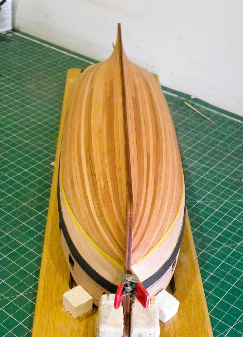


- 332 replies
-
- 21
-

-
- Harpy
- Vanguard Models
- (and 1 more)
-
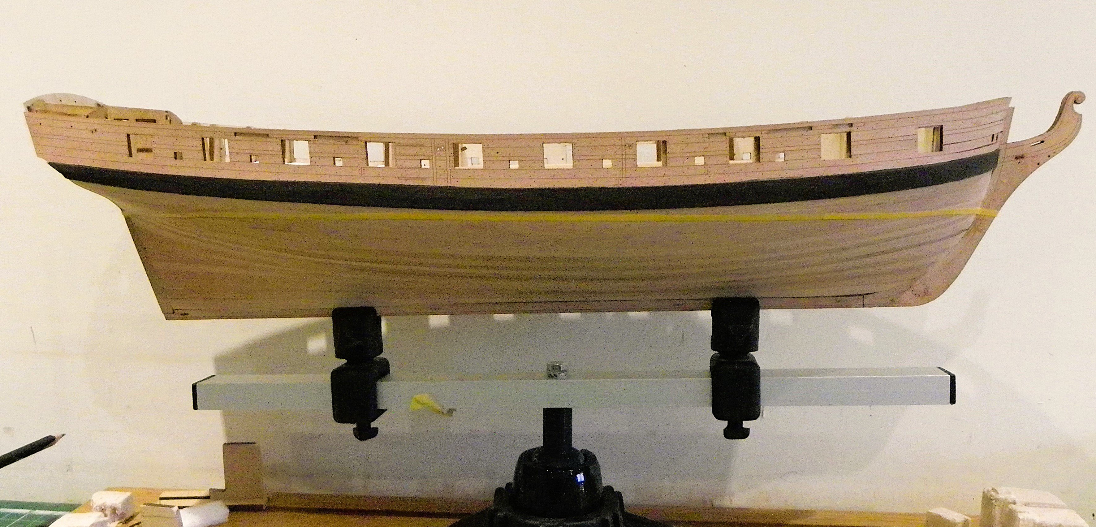
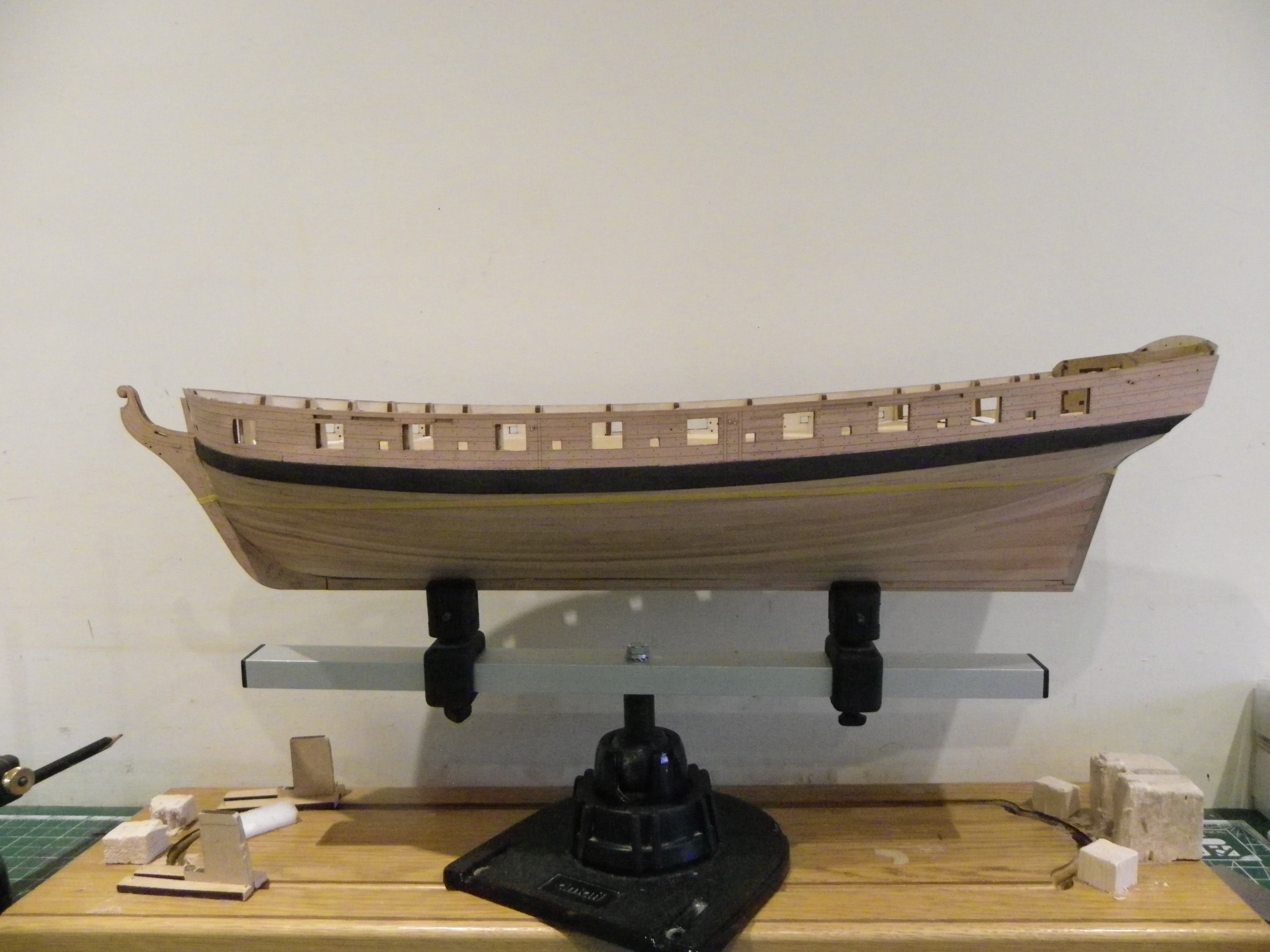
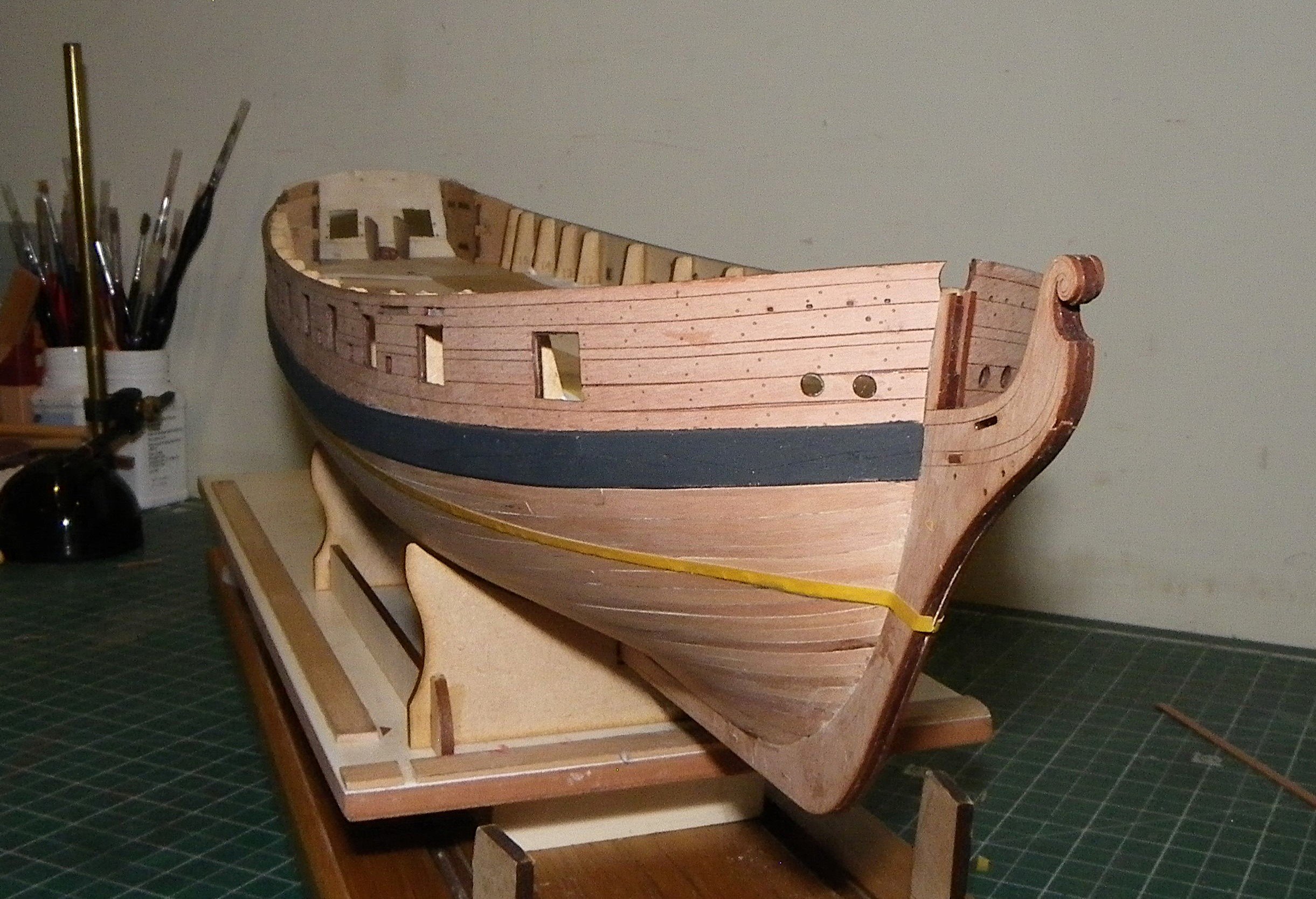
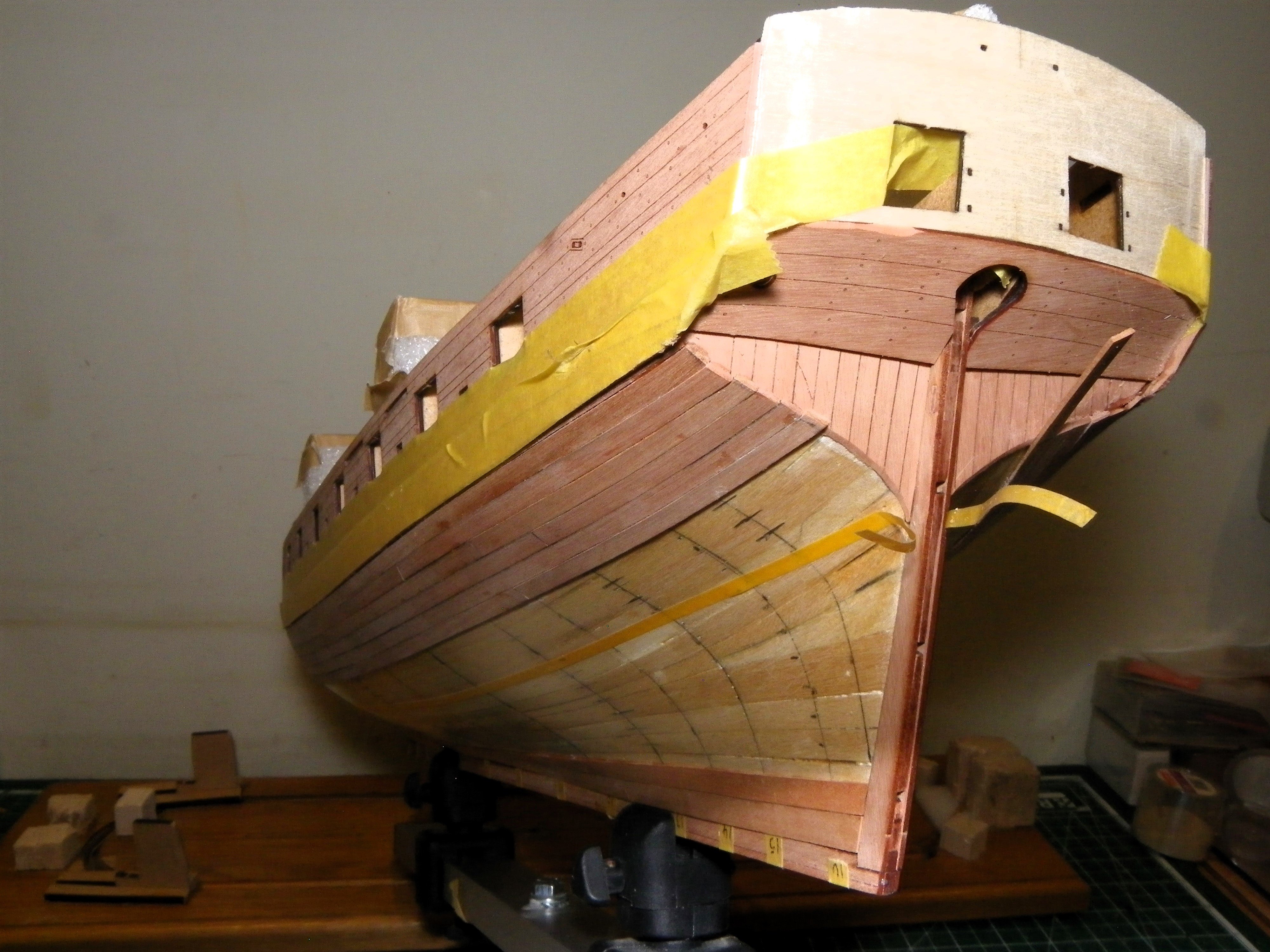
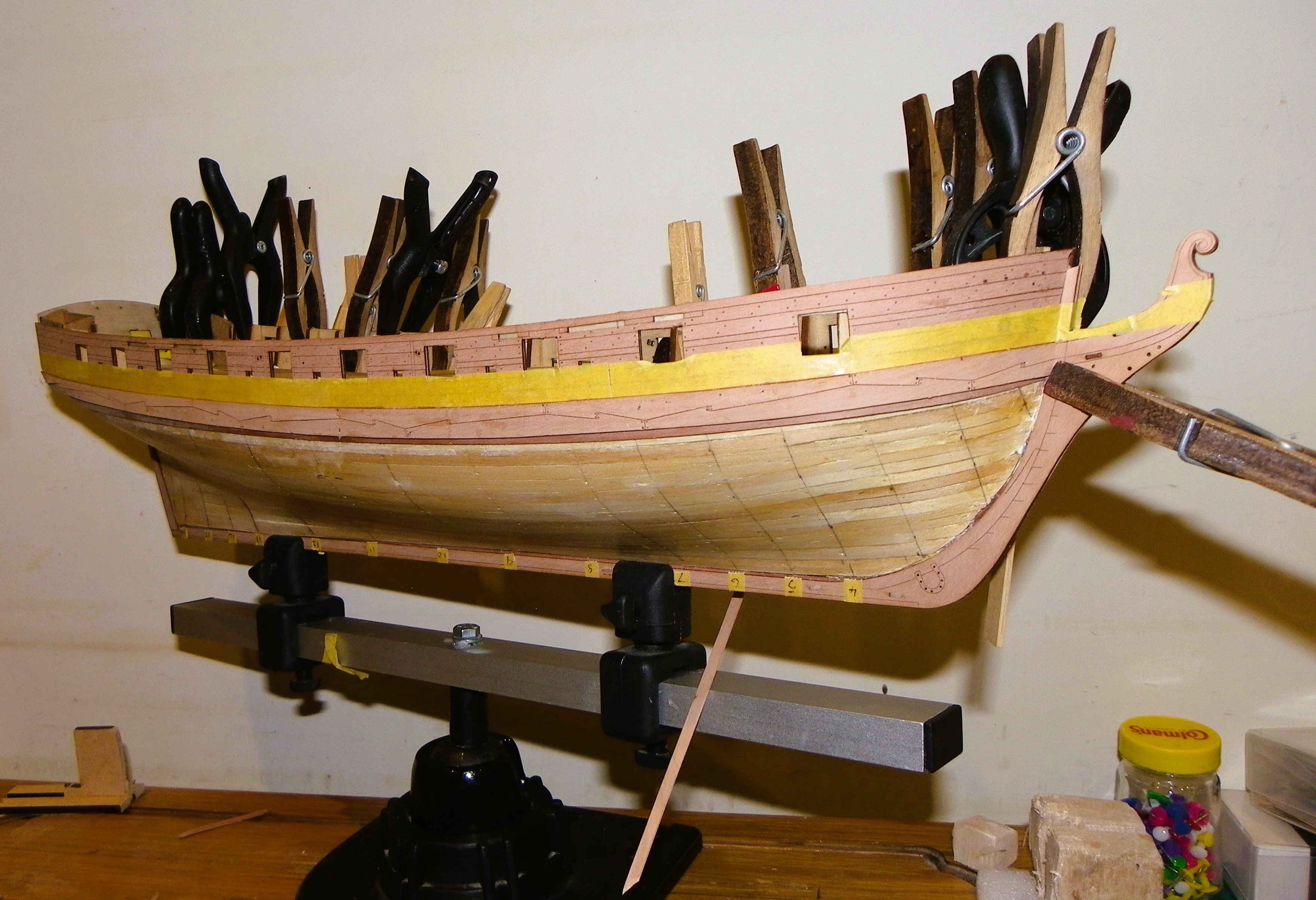
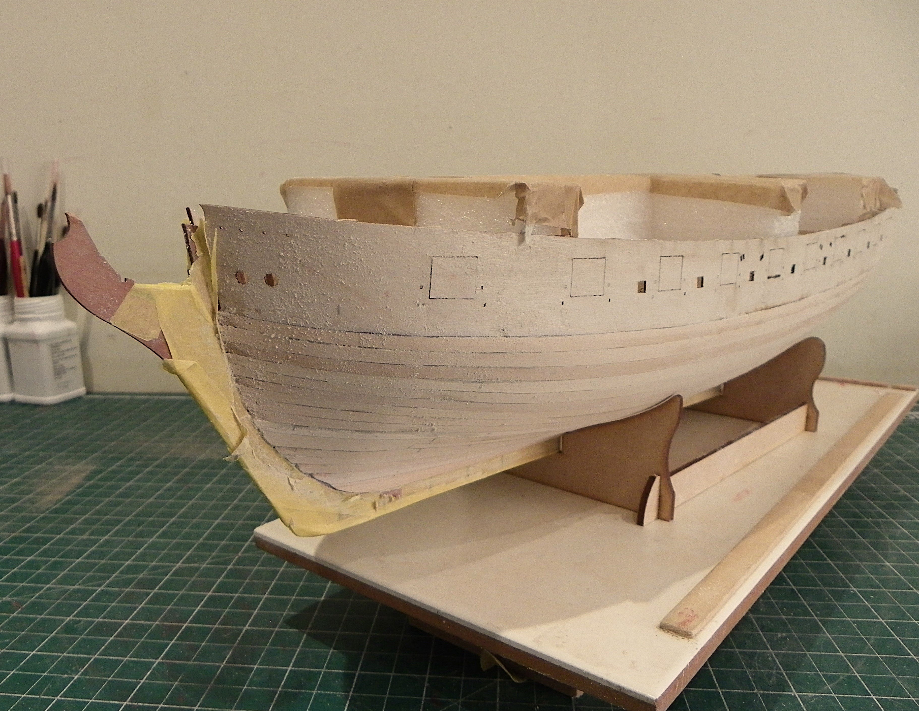
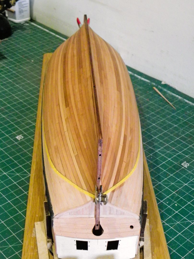
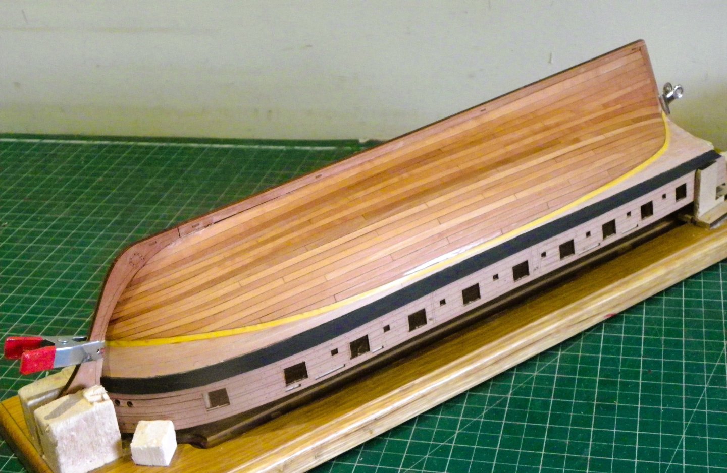
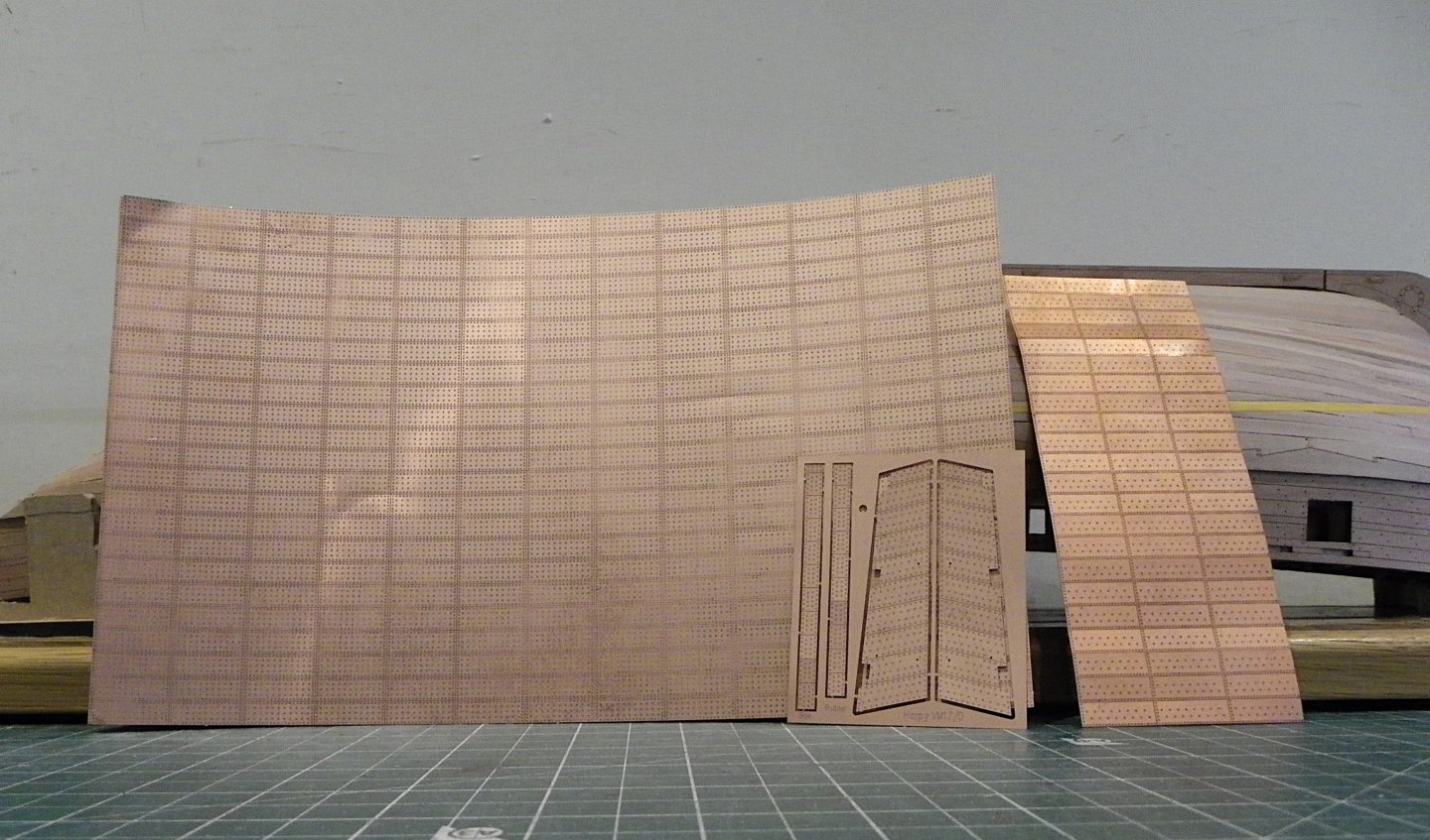
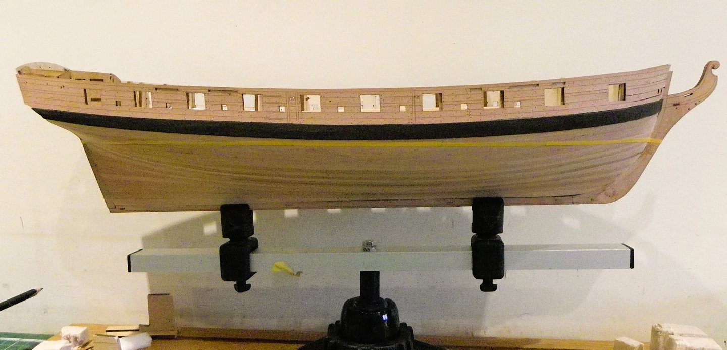
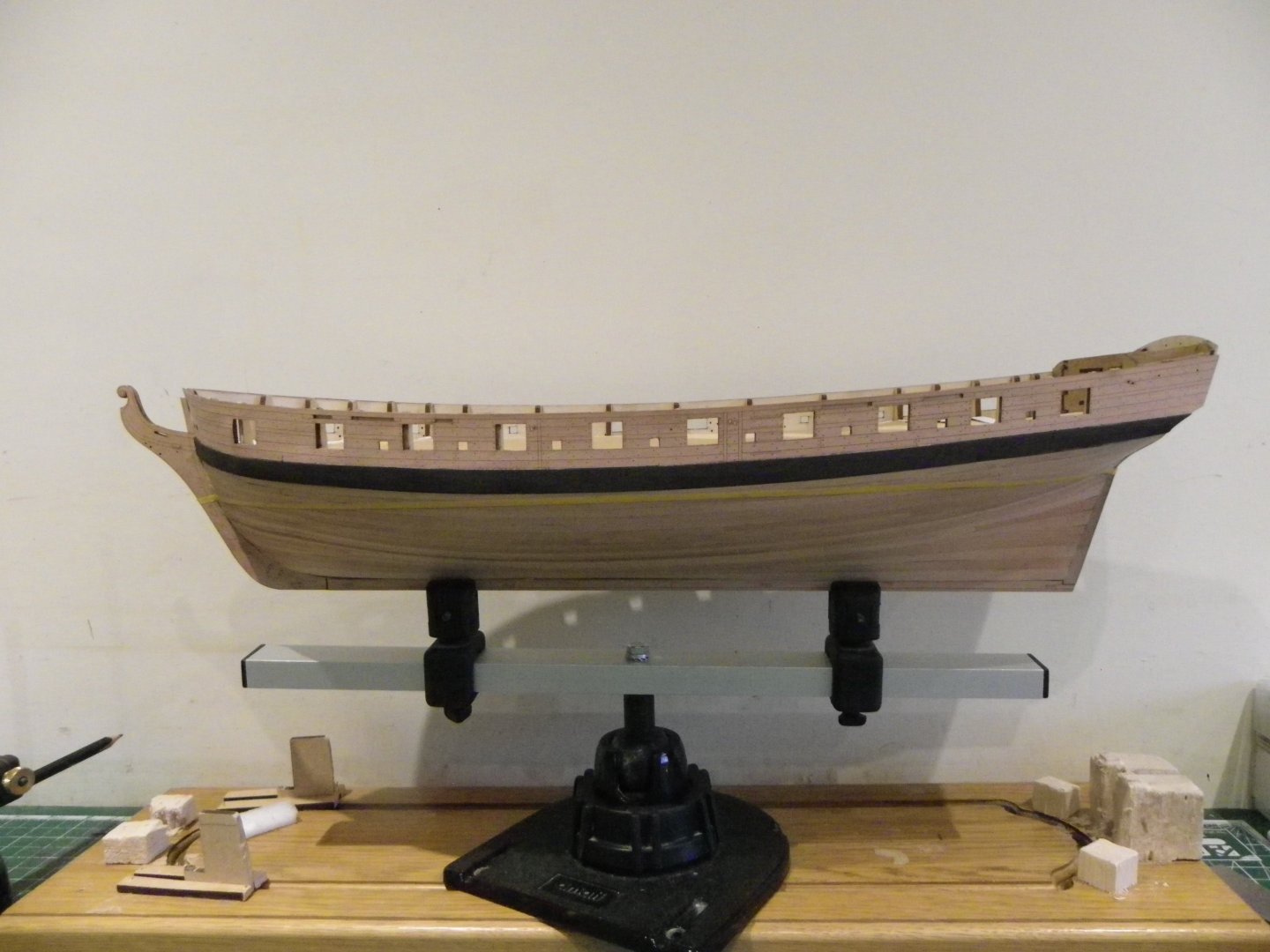
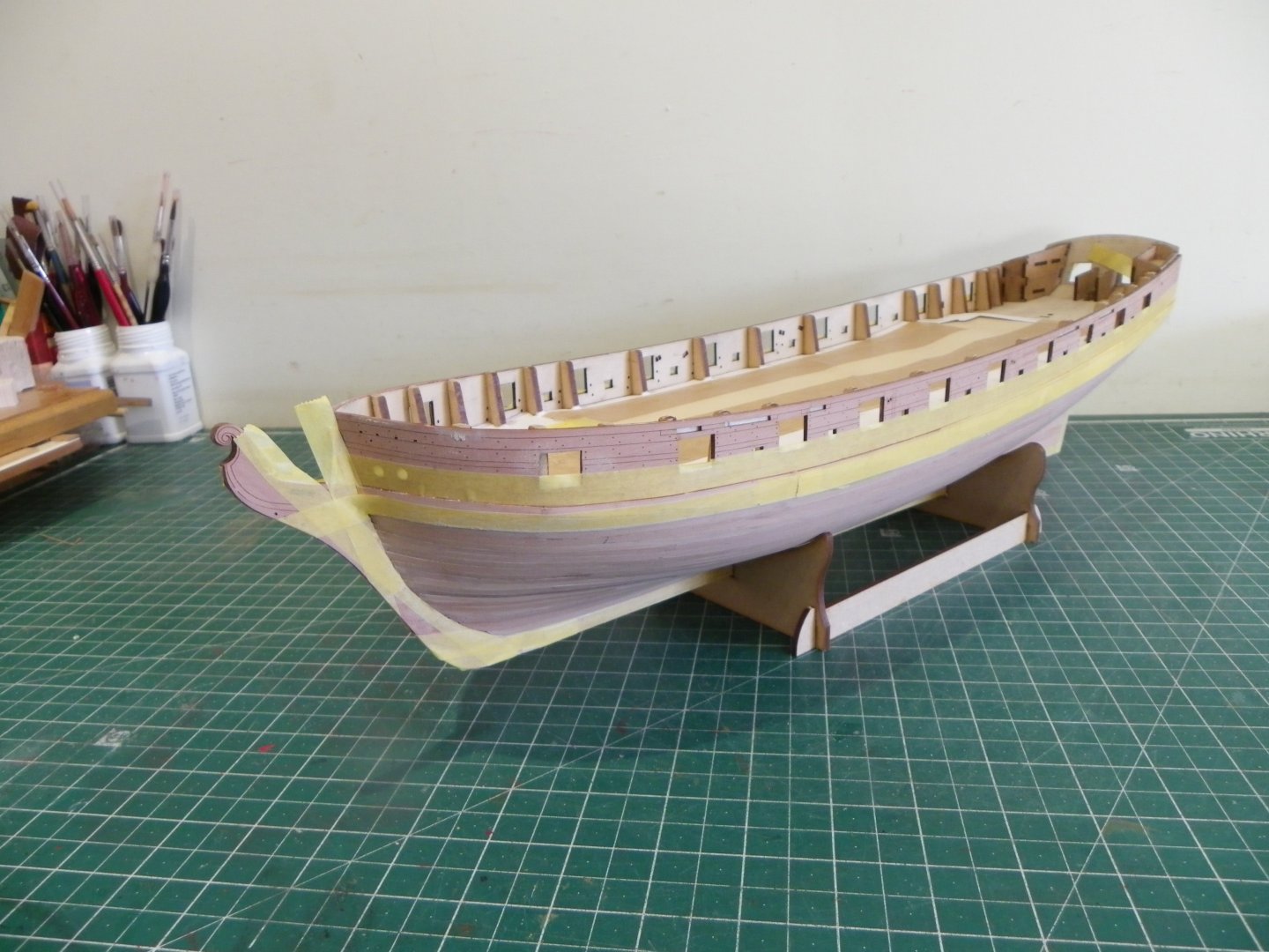
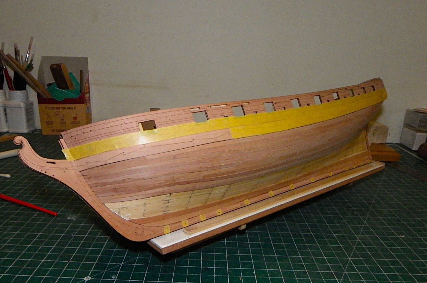
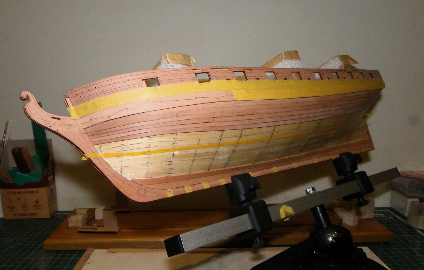
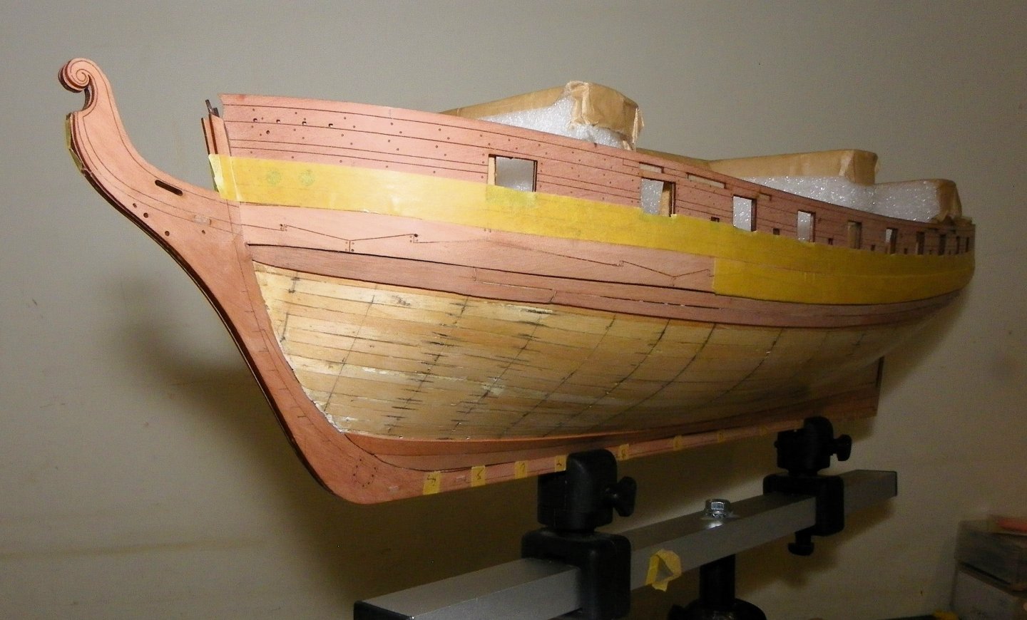
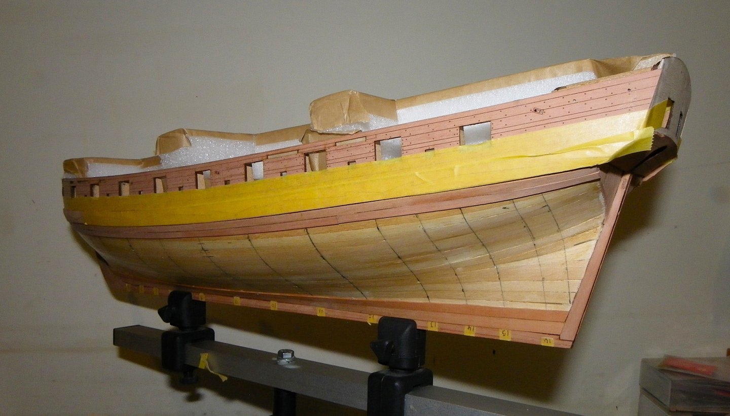
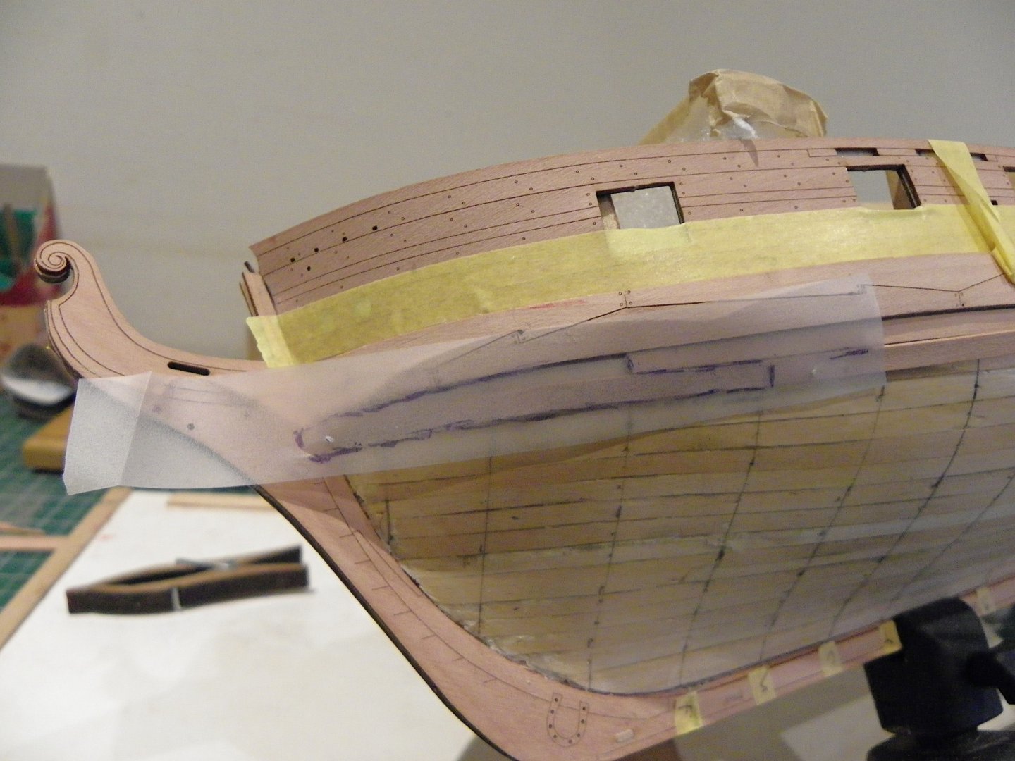
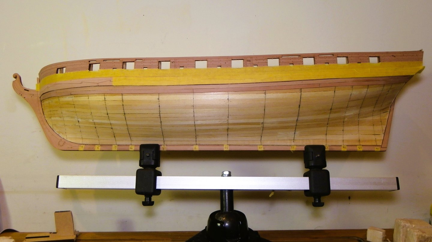
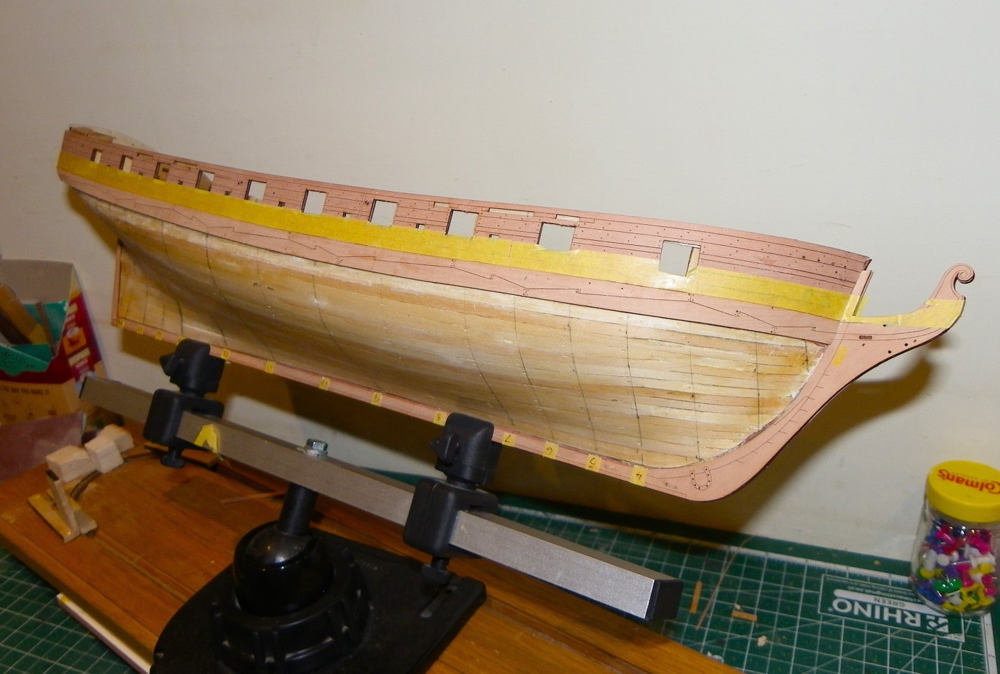
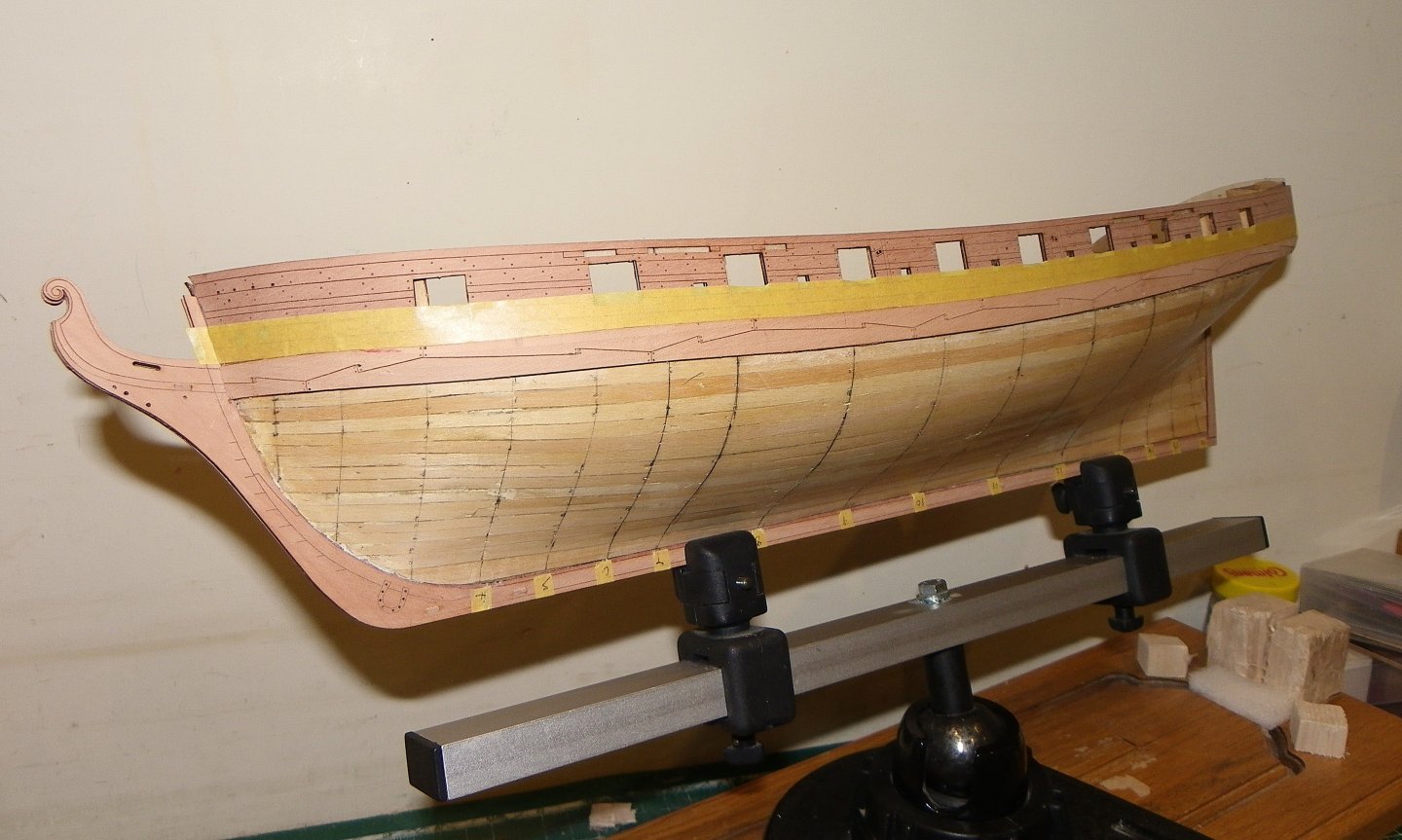
Post 29 Preparing to Copper the Hull. I have decided to copper the hull, the first since my Pegasus build, way back in 2011. At this point in the build the kit instructions suggest moving onto progressing the fitting of the deck, and inner bulwarks before coppering the hull. My inclination is to copper the hull before I do any more internal fitting which may be scuffed or damaged with the hull inverted. Having dodged doing waterlines by leaving the hulls of Sphinx and Indefatigable varnished wood, I must attend to this first. 0114 Not one of my favourite jobs and it usually takes several goes to get a line I am happy with. 0122 0133 0134 0116 0142 0143 0148 I may still tweak the line at the bow a fraction, as I recall the words of Dr C.N. Longridge in relation to coppering Victory. If you lay your copper strakes strictly up to the line you will be very disappointed when you have finished the coppering because it will appear to sag downwards at the bows and stern. This is an optical illusion produced by the curving inwards of the ship’s body. To prevent this you must raise the line at each end of the ship and then the top line of the copper will appear horizontal. Begin to raise the line at the level of the Foremast and Mizen which is roughly where the cant frames begin. Victory of course has a much bluffer bow and the degree of tweaking will differ between ships, but something to bear in mind. 0149 This is a good point to get some paint down on the wale altho’ many touch-ins will be required before the model is complete. I am using Vallejo Black/grey which I think gives a better scale tone. I am using the Vanguard supplied plates rather than use copper tape. 0129 Three very thin sheets of plates are supplied marked with the nail patterns. There is also a separate set for the rudder and stem face plating. Unlike the Amati plates (smaller strip to right) I have used previously, these are not handed Port and Starboard with nail markings to represent an overlap, nor are the plates so obviously scored for removal. The Vanguard Plates do come easily away with careful bending. The plates are a close match to the Amati version and with regard to relative costs there is not a lot in it. B.E. 02/02/2025


- 332 replies
-
- 17
-
-
- Harpy
- Vanguard Models
- (and 1 more)
-
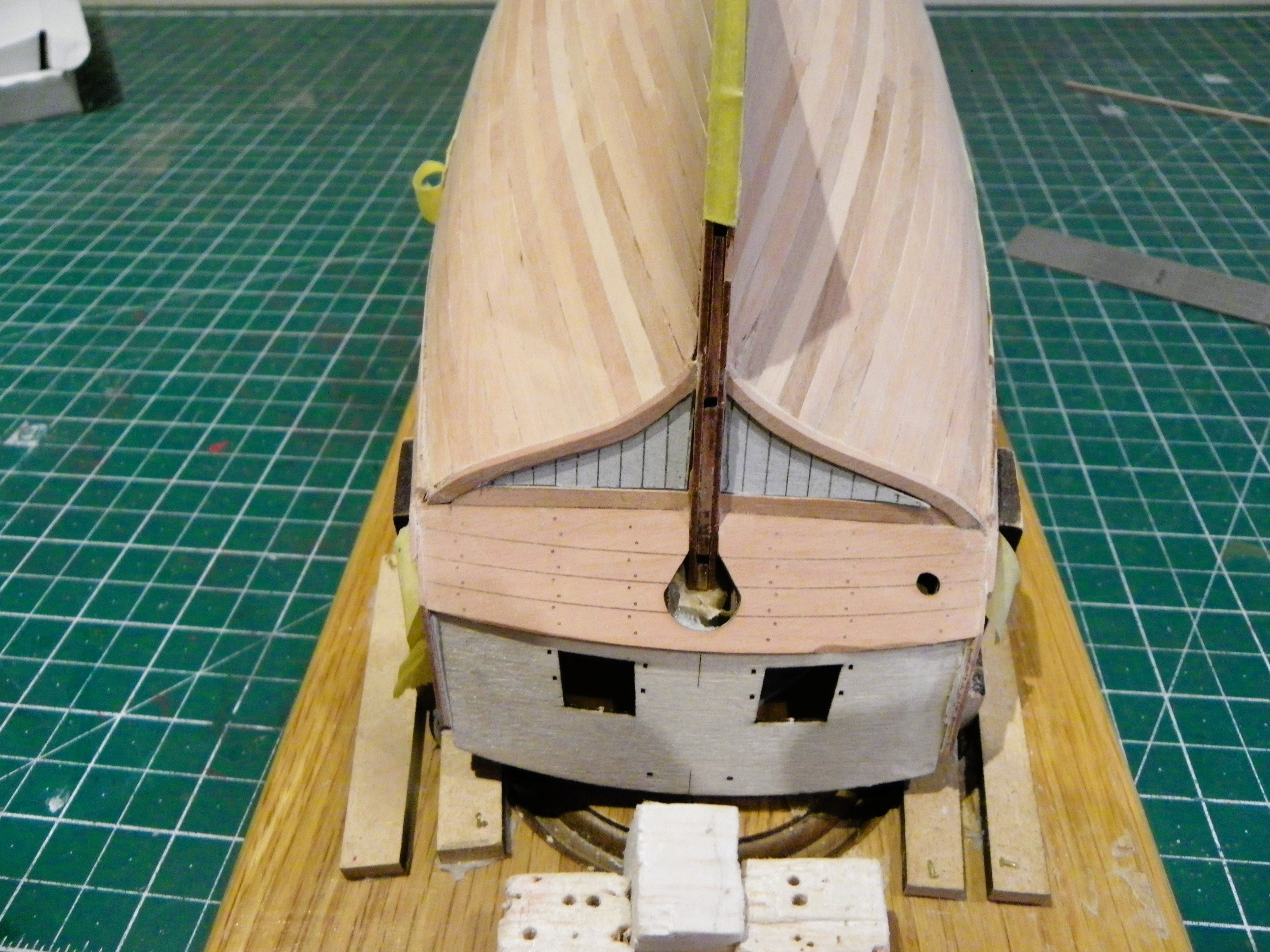
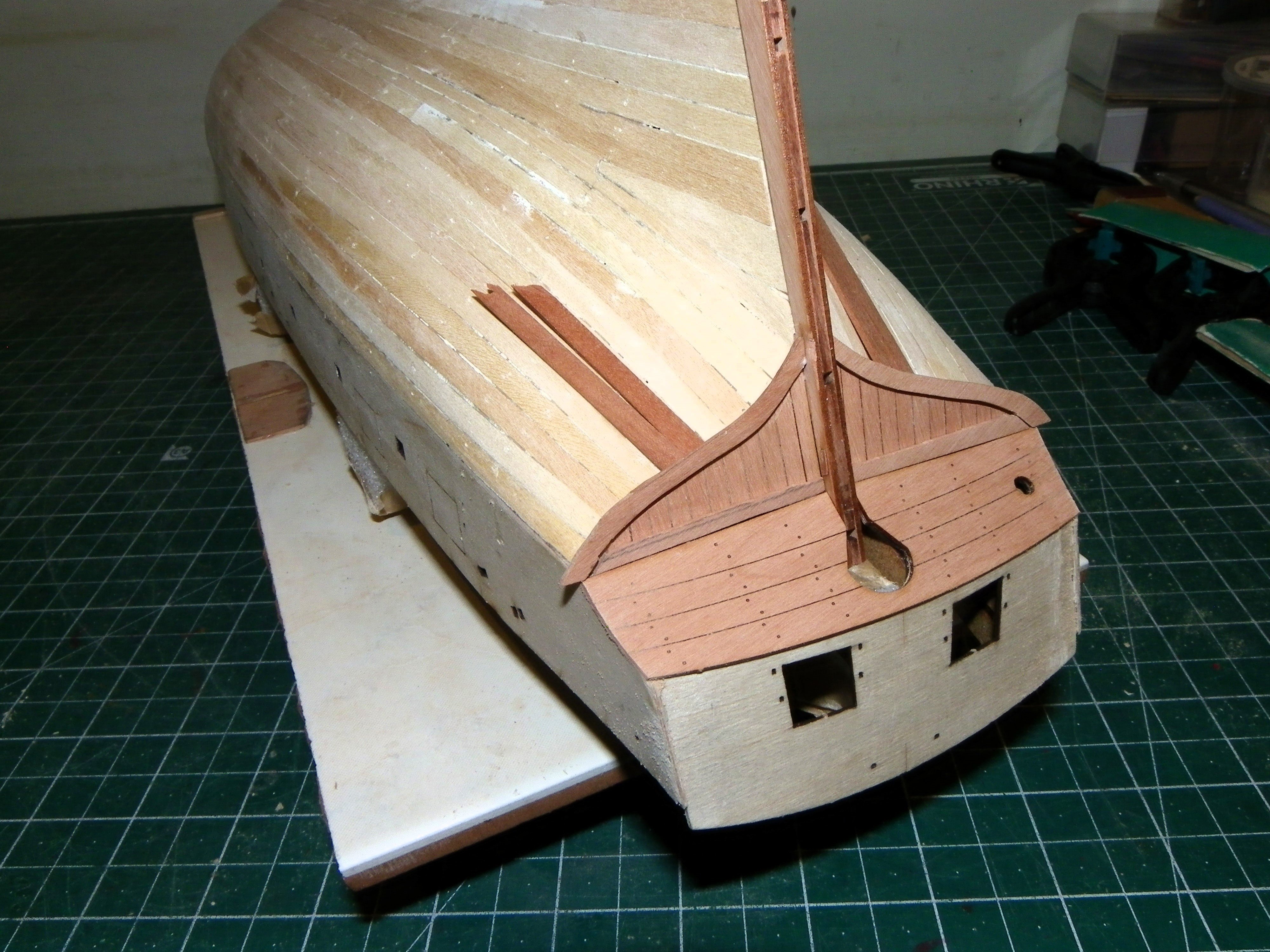
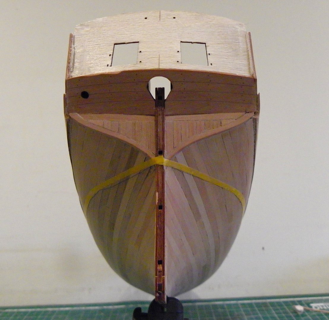
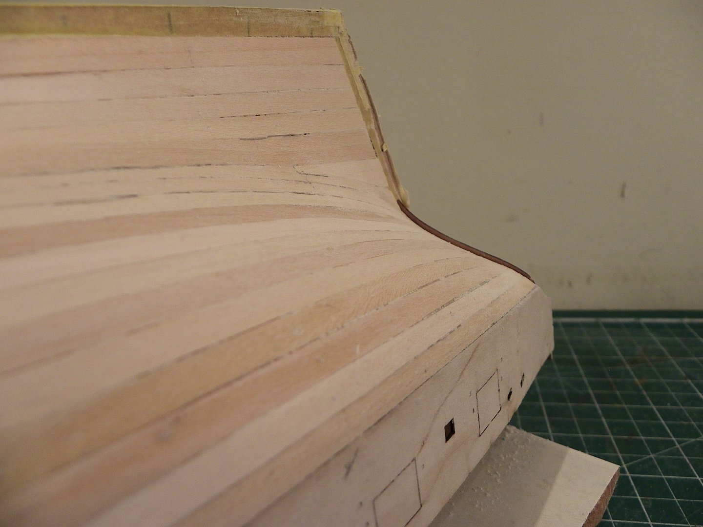
Post 28 The Square Tuck I had played around with framing the Square Tuck earlier in the build. 089 Neat as it is I was trying to avoid the exposed end grain planking of the kit arrangement and add a sort of faux framing to better represent a more authentic look. This is what I have come up with. 090 I had made the ‘frames’ earlier. 092 The original laser cut boarding below the framing. 094 The boarding fitted between the frames consist of eight boards of decreasing length which would prove tricky to fit individually. I opted to board over a template card pattern off-model and fit as a single unit. Still involved a careful trim and dry fit by degrees. 096 099 The boarding is then sanded flush with the frames. 0104 0109 B.E. 01/02/2025


- 332 replies
-
- 15
-
-
- Harpy
- Vanguard Models
- (and 1 more)
-
Thank you Mark, Bug, Cisco, and John for your appreciation. @ - Cisco, I am an admirer of your AVS build, and those three months were well spent, and it shows. Your planking is simply beautiful, makes mine look very average. Post 27 Final sanding was done using various grade papers, primarily 320 al.oxide. It didn’t take long to achieve a smooth and even surface. 070 072 073 077 087 I think she has scrubbed up quite well. I now return to the Square tuck. B.E. 31/01/2025


- 332 replies
-
- 18
-
-

-
- Harpy
- Vanguard Models
- (and 1 more)
-
That should provide an excellent base for the 'show' planking.👍 B.E.
-
Good looking copper job, and a great looking hull.👍 I don't tend to varnish copper plating on my builds, I prefer the 'old penny' look, but it's all down to personal choice. B.E.
- 20 replies
-
- 1
-
-
- Indefatigable
- copper plates
- (and 1 more)
-
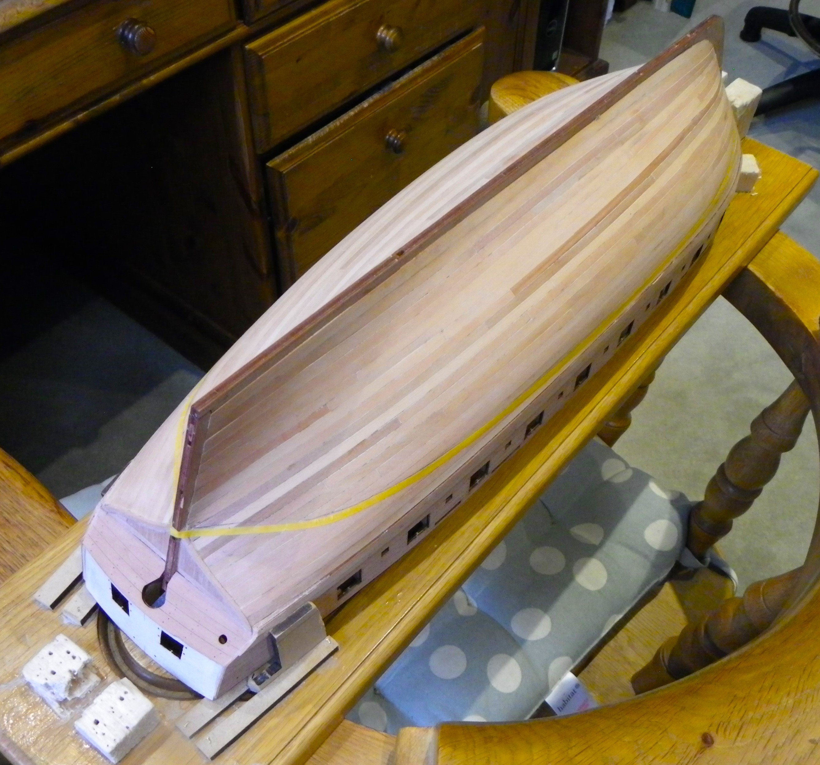
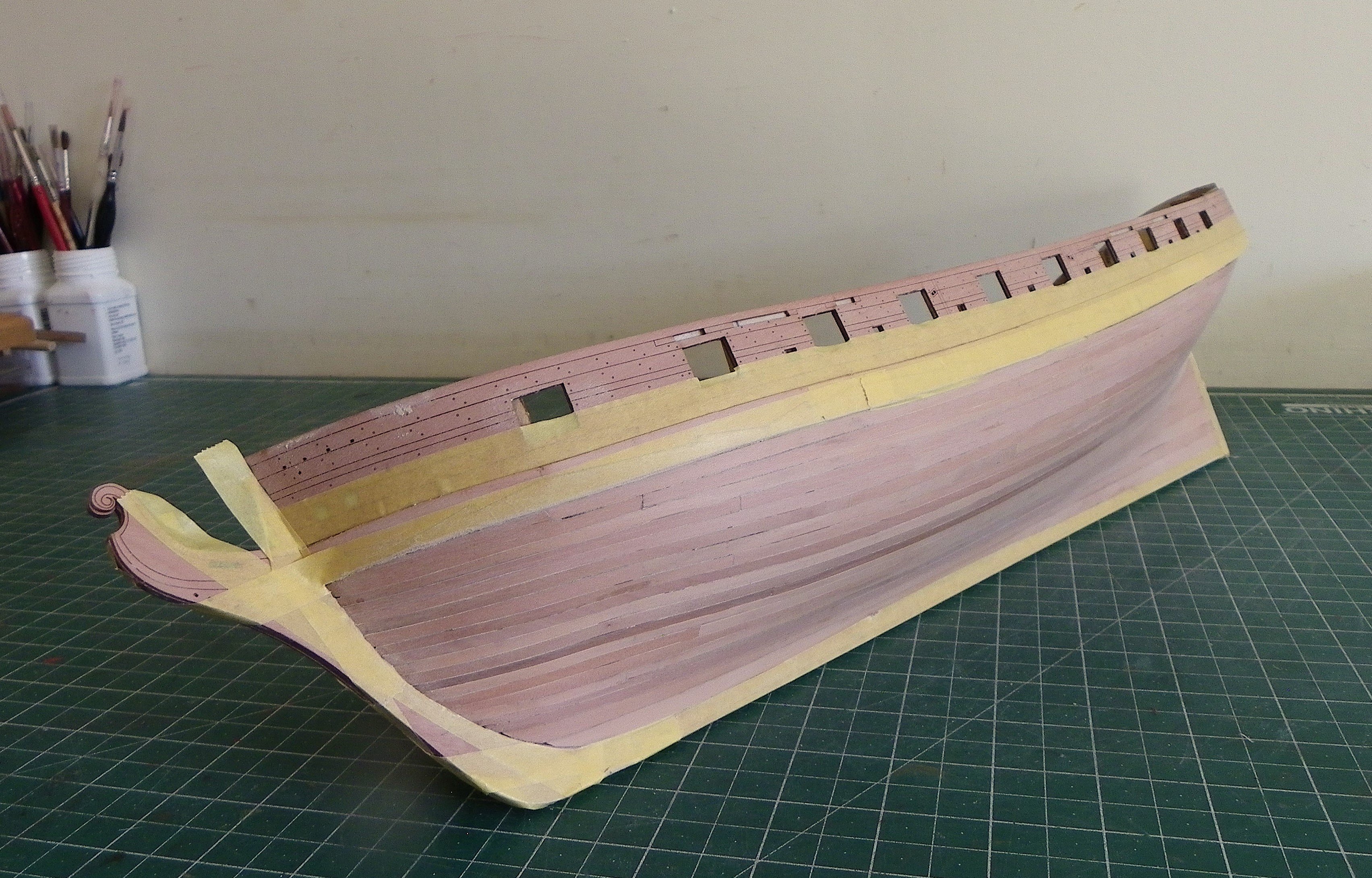
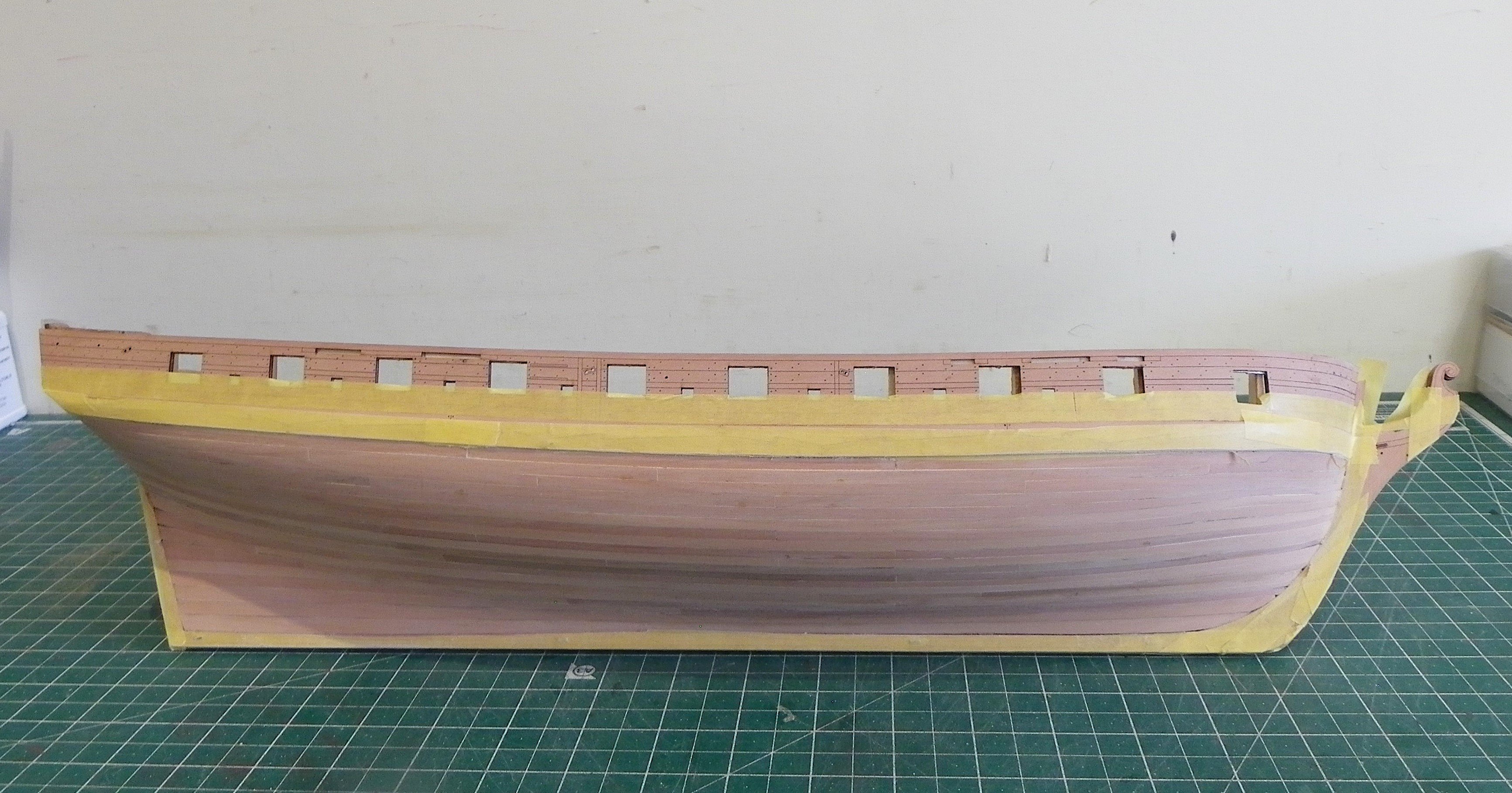
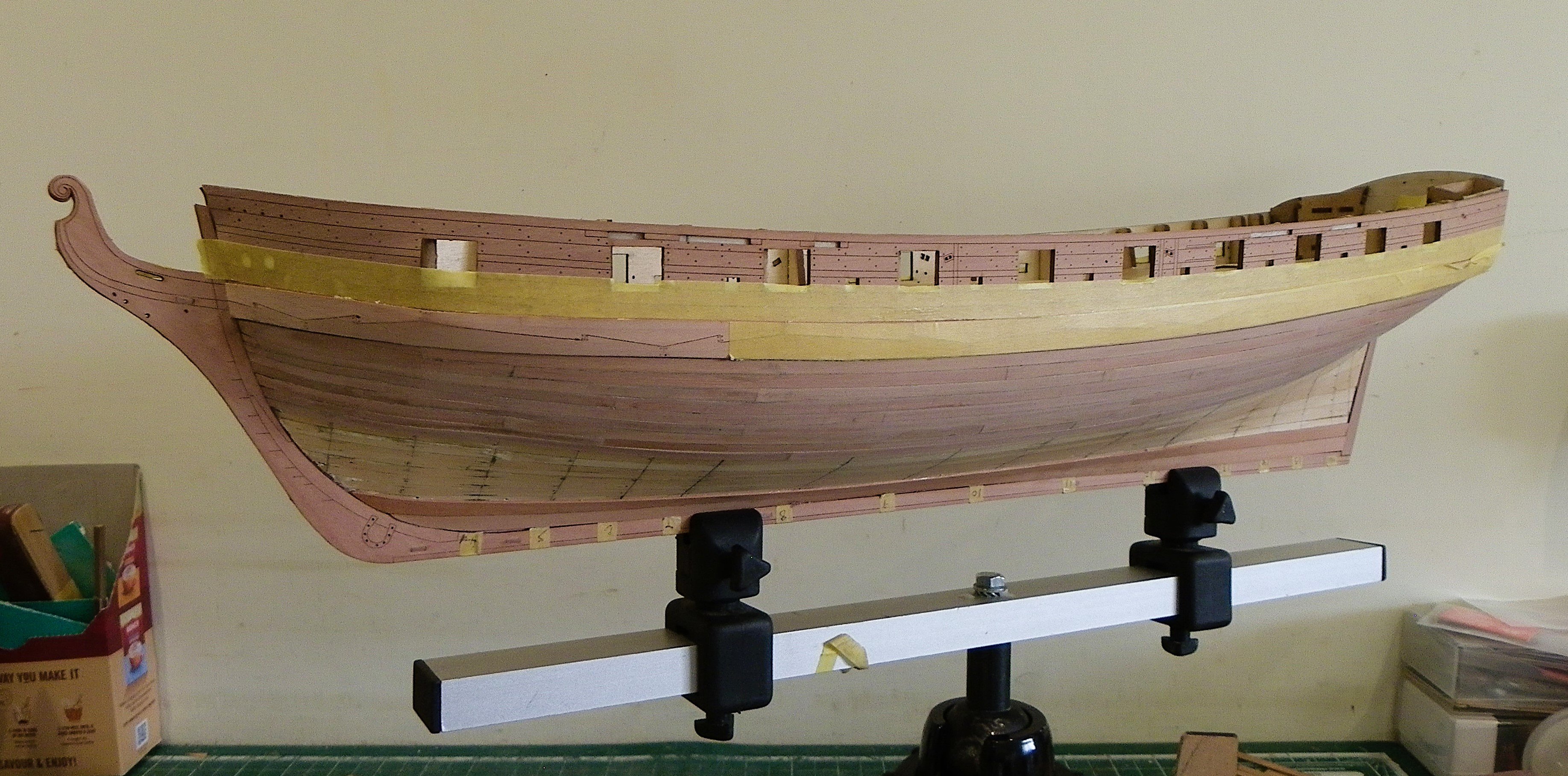
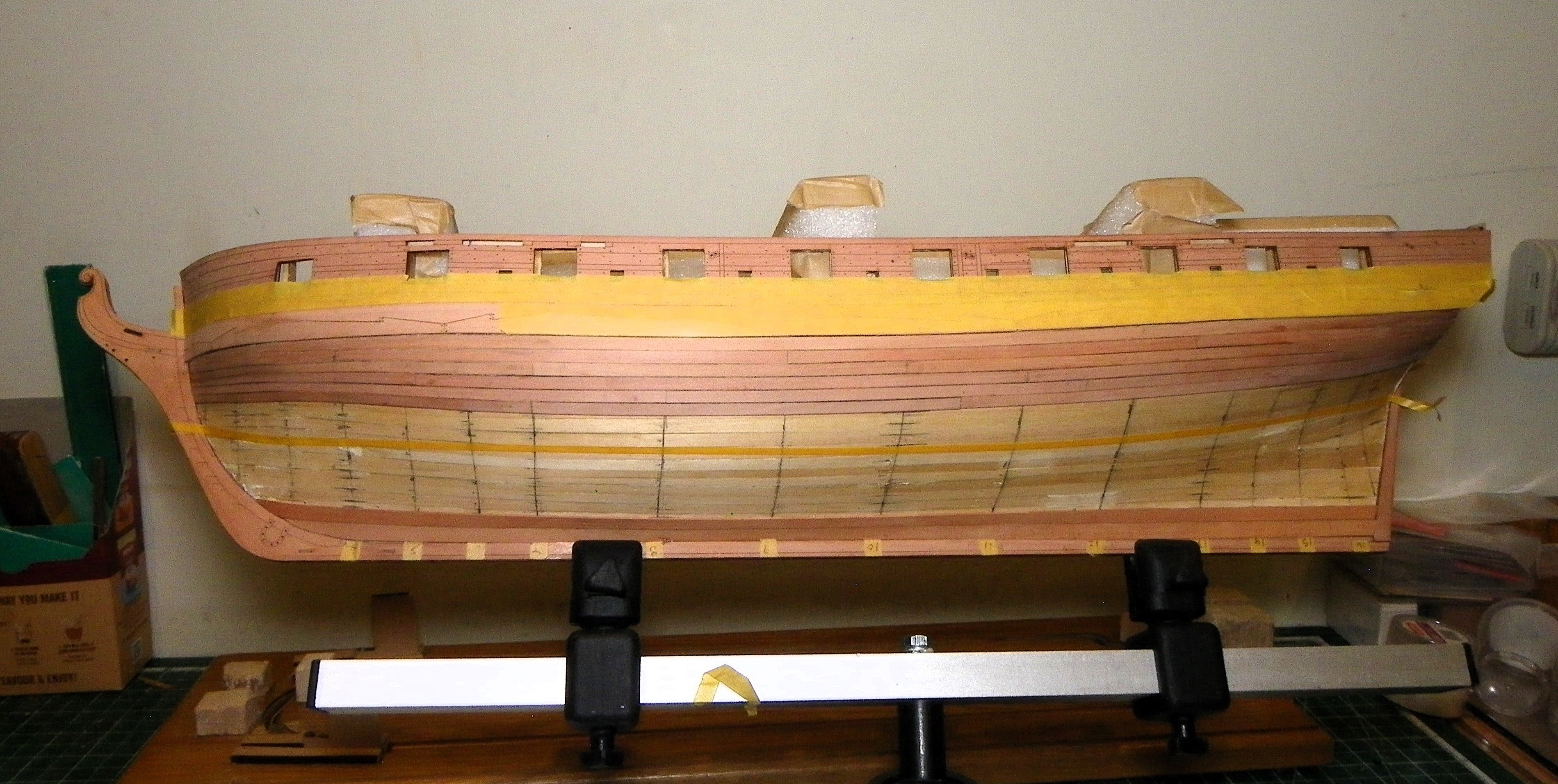
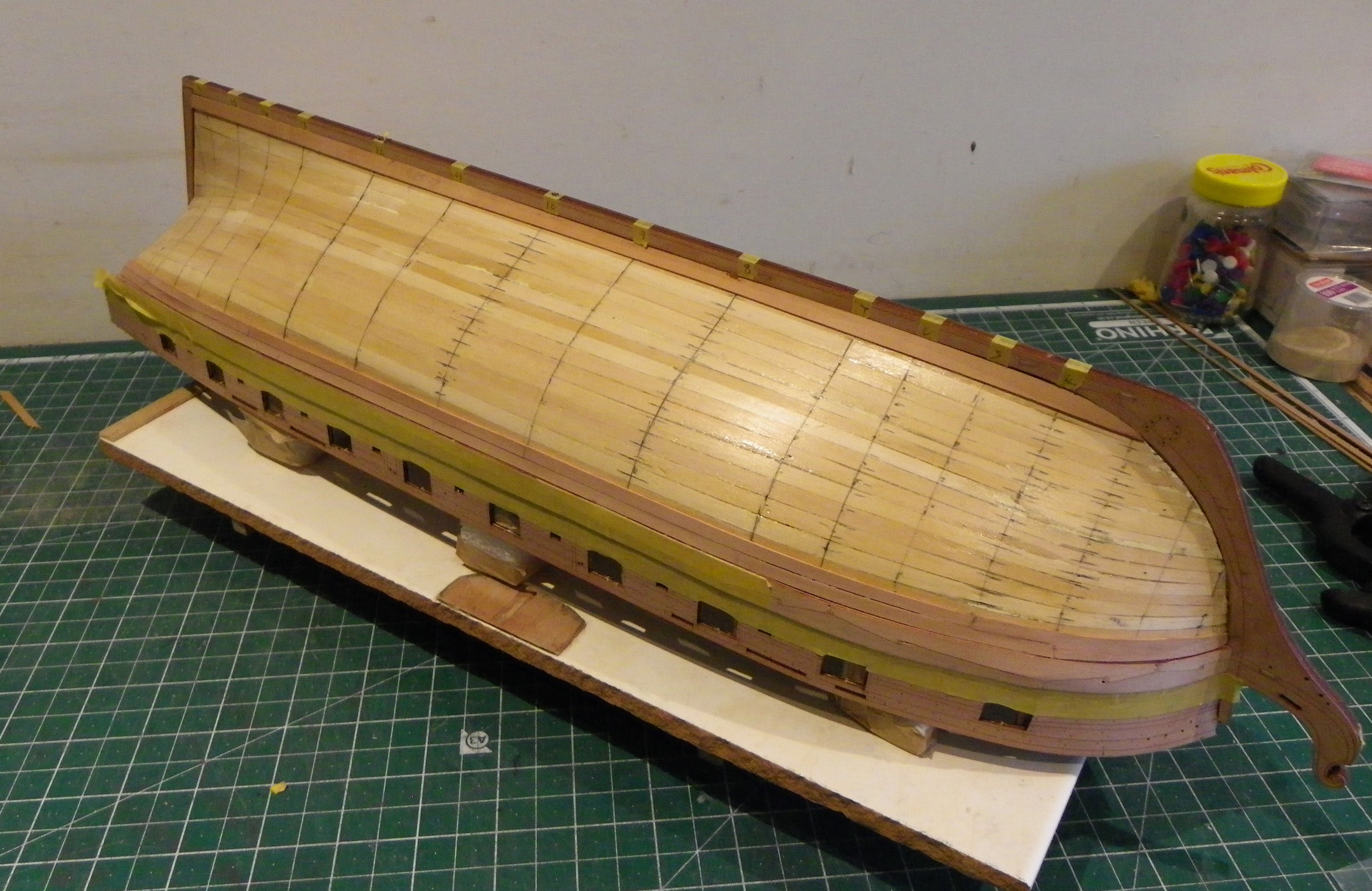
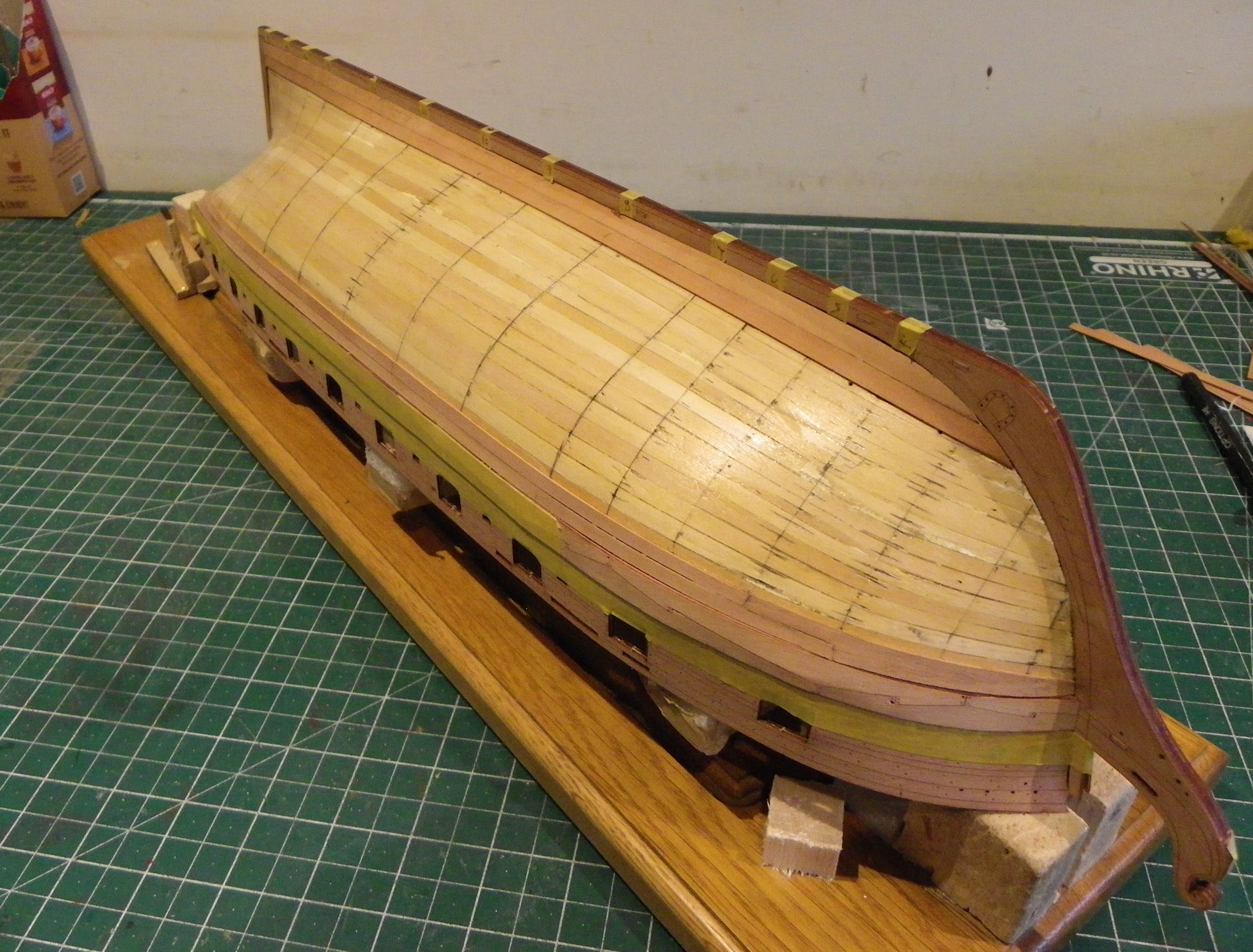
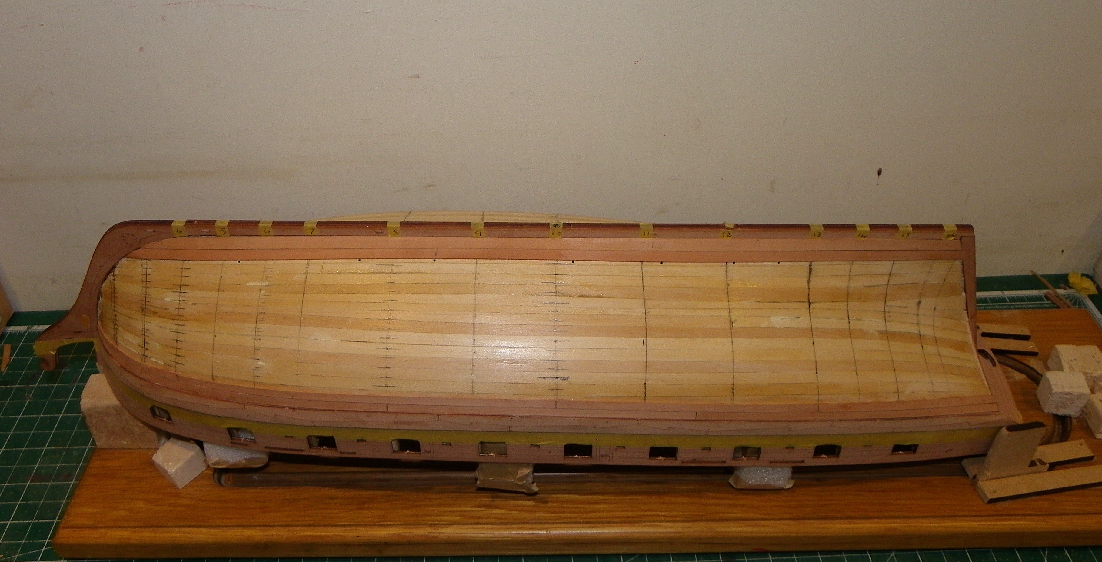
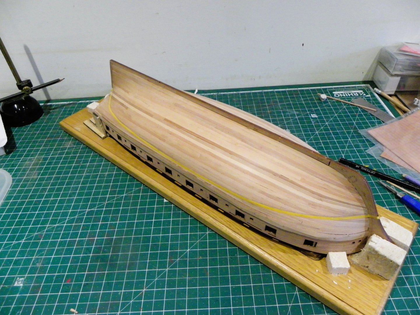
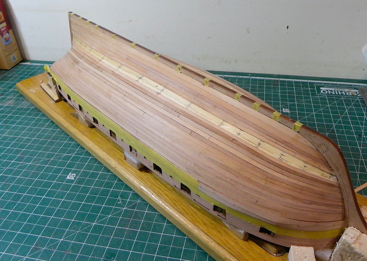
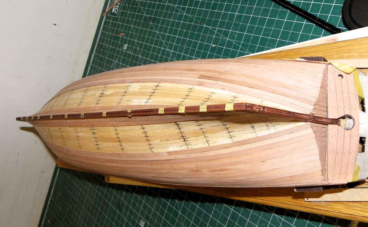
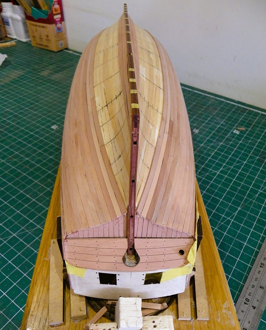
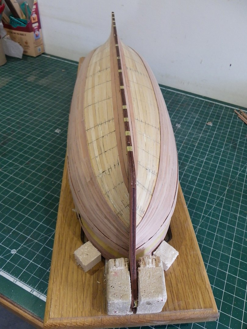
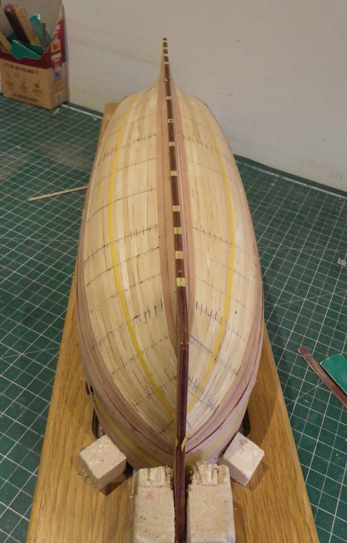
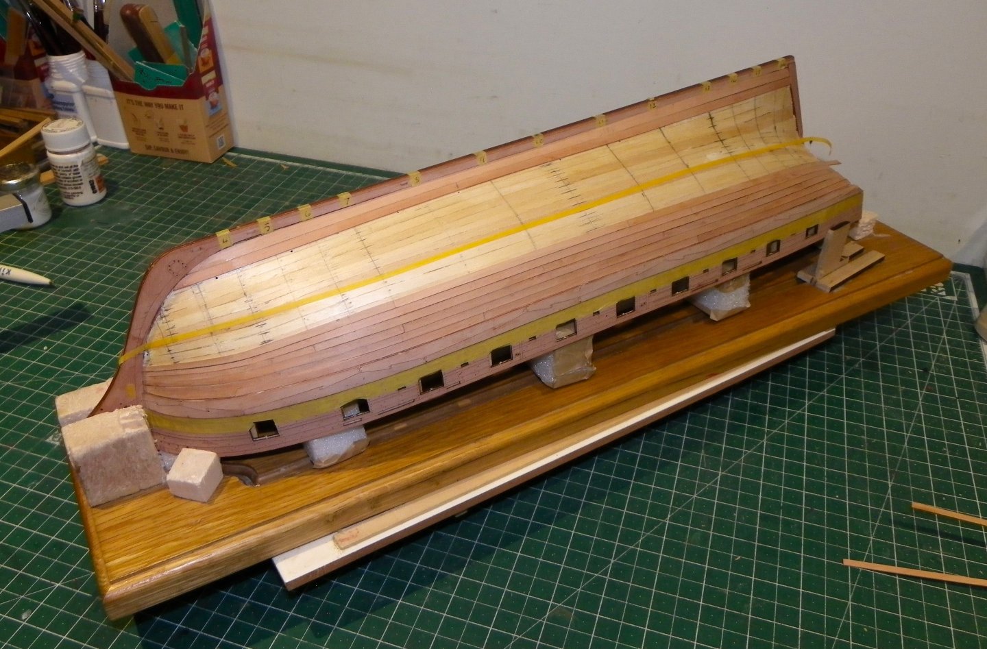
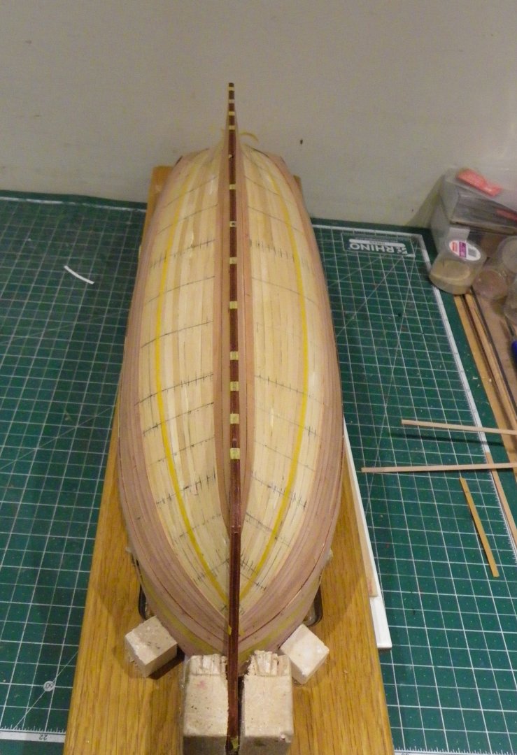
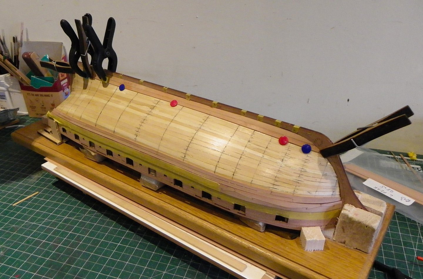
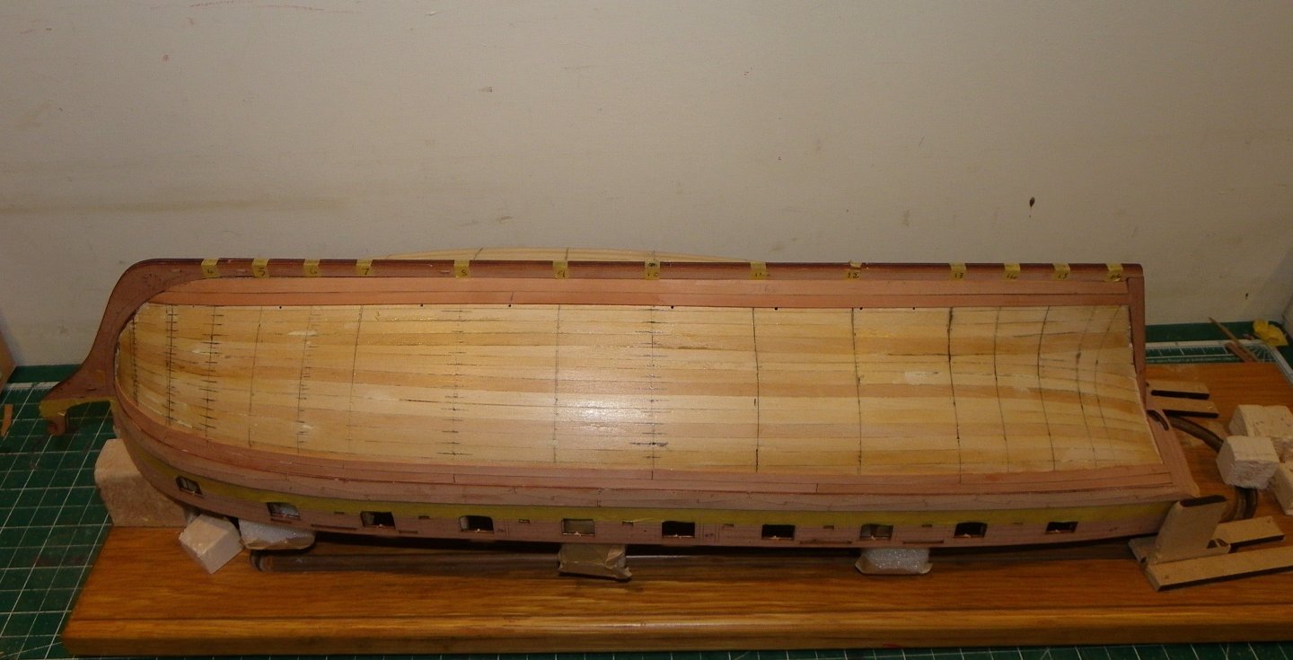
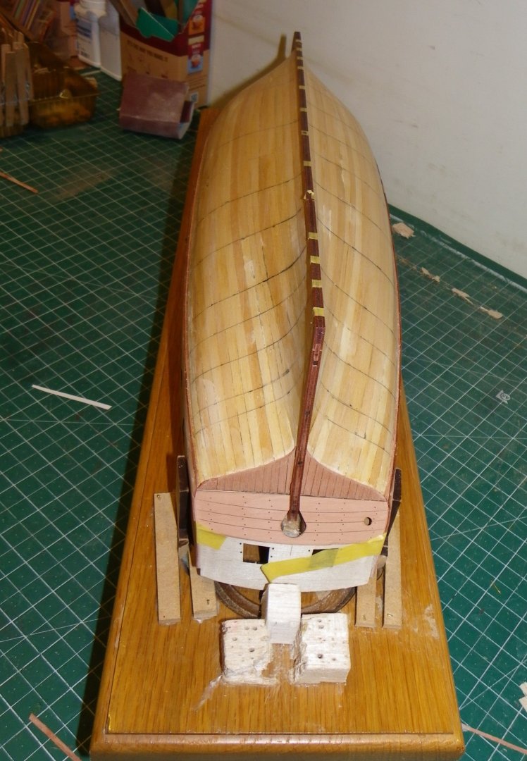
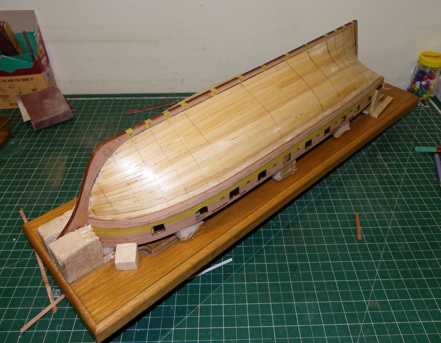
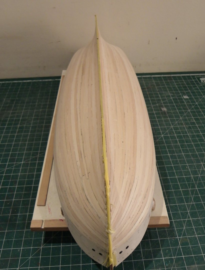
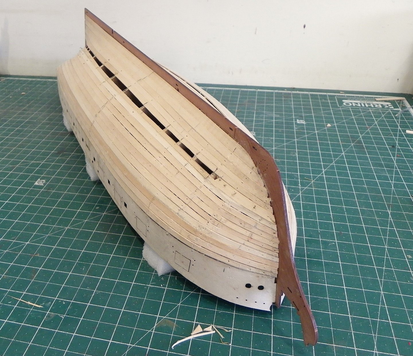
Thanks Guys for the interest and likes. @ Glenn - yes I use edge bending, but when it becomes excessive it creates the less than appealing exaggerated sny effect,. Post 26 Completing the Pear planking. 004c Each station has been re-marked on the hull, hopefully for the last time, but I don’t discount that a little tweaking may still be required. I begin with the strake above the keel. 011c This strake runs from 2mm at the bow, 4mm at Midships, increasing to 5mm at the sternpost. I am now working alternatively from keel up and wale down. 007c It is easier to deal with the aftermost section of a strake as a separate plank. 0017 Three strakes to go. It can be seen in this shot that the space at the stern is gradually equalising strake upon strake as I close the gap. 021 Two strakes to go. 026 One strake to go… 030 028 I did not find it necessary to use stealers at the stern, as I have a selection of planking strips of various widths. In the absence of these, the kit Pear sheets that contain the laser cut parts, provide a good source of plank making material suitable for spiling wider sections at the stern. The final strake which sits below the round of the hull lacks uniformity which is why it is placed where it is. Of necessity the planks are spiled, an exercise I quite enjoy; getting them to fit neatly into the given space I find quite relaxing. The strakes are again divided into three planks per strake which makes things easier. 041 046 053 058 All done! Overall, I’m fairly happy with the planking even in its unsanded state. Moving on to cleaning up. B.E. 30/01/2025


- 332 replies
-
- 31
-
-
-
- Harpy
- Vanguard Models
- (and 1 more)
-
"Stop! this is shoddy workmanship and is simply not acceptable". Good decision Glenn 👍 B.E.
- 241 replies
-
- 5
-

-
-
- Vanguarrd Models
- Harpy
- (and 1 more)
-
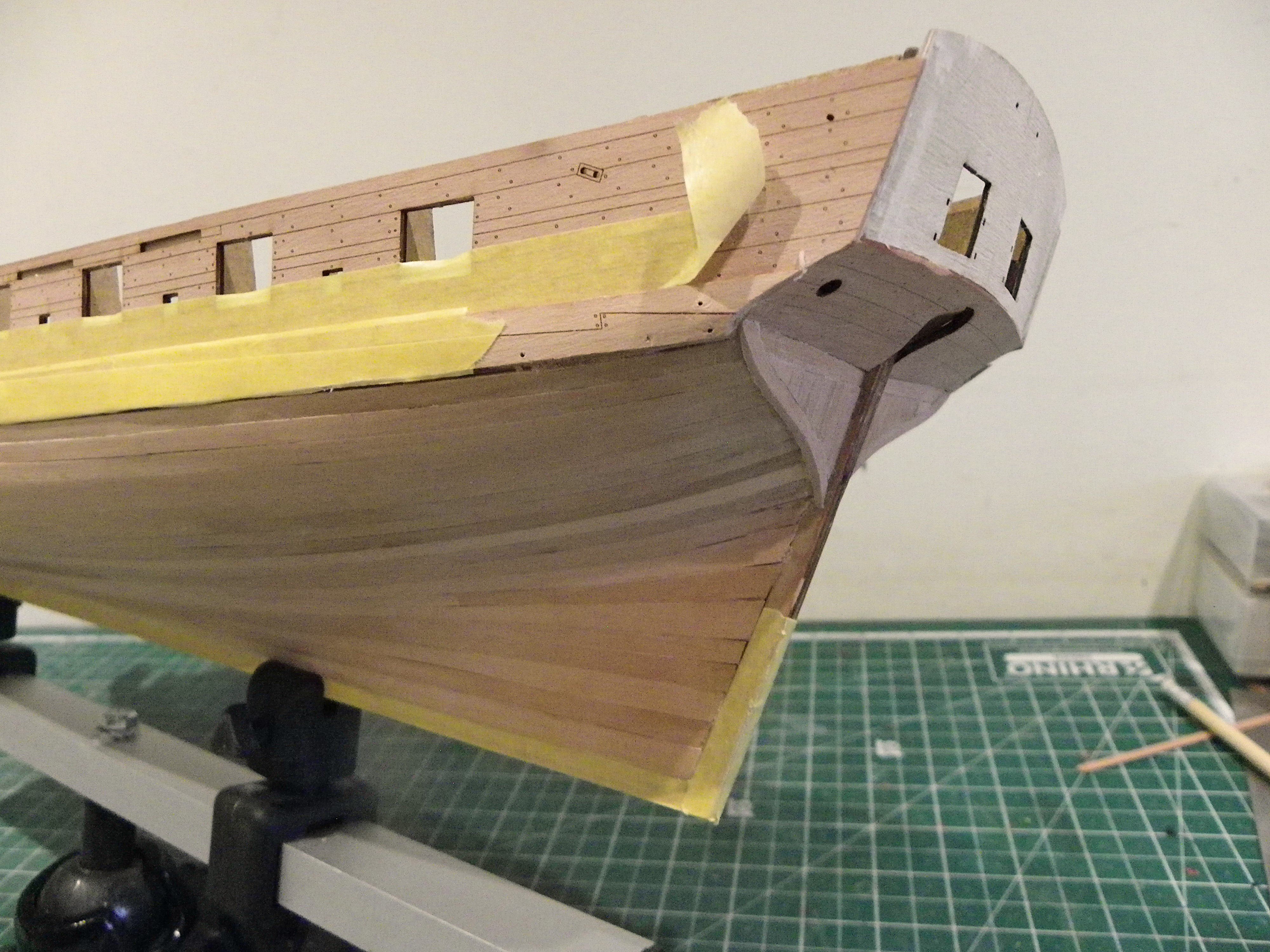
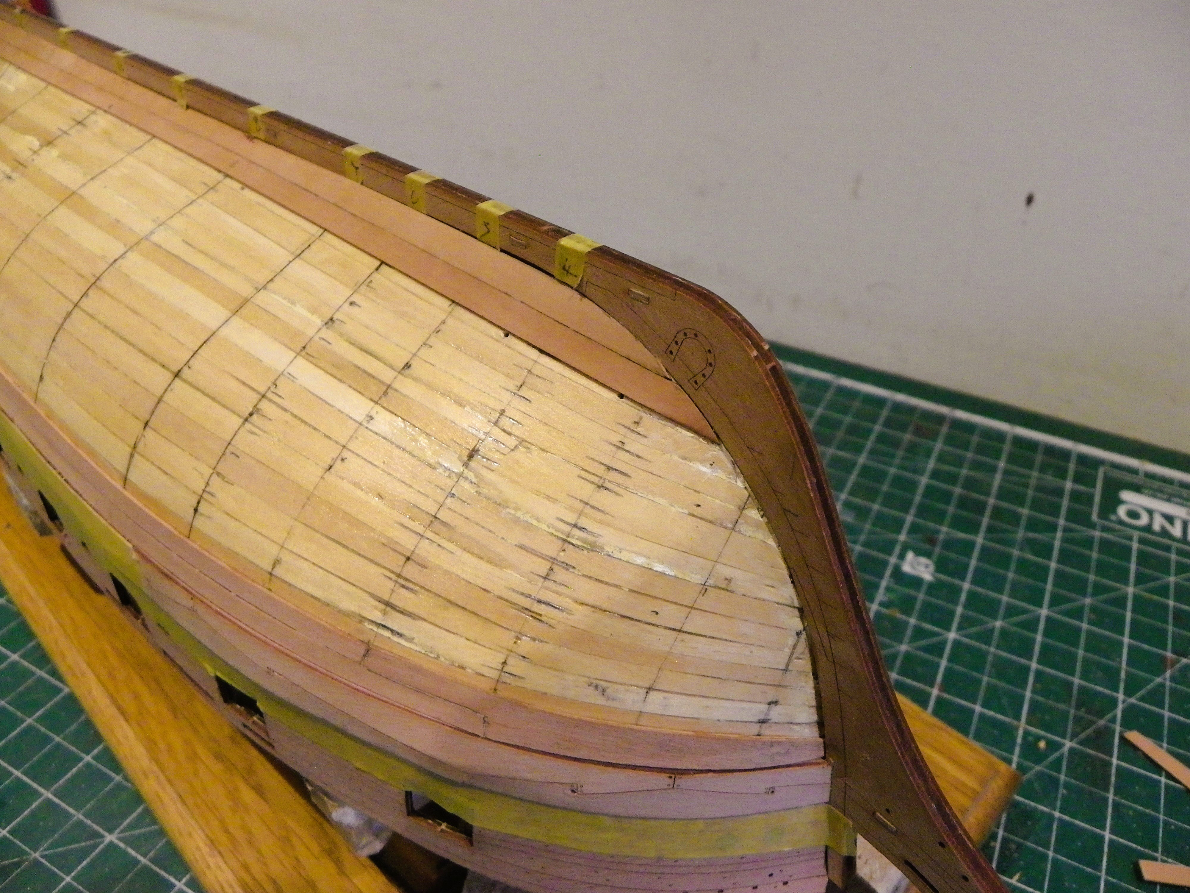
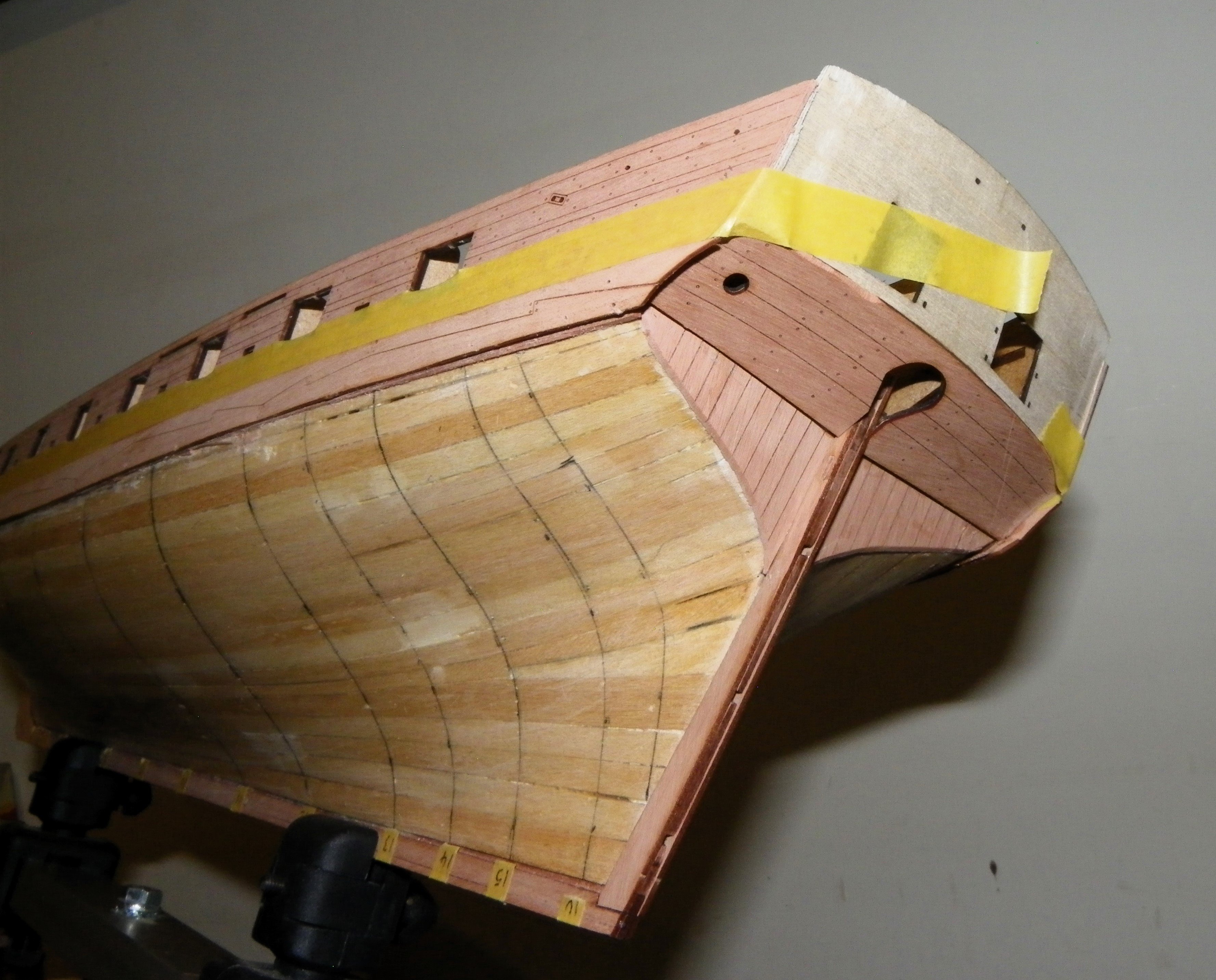
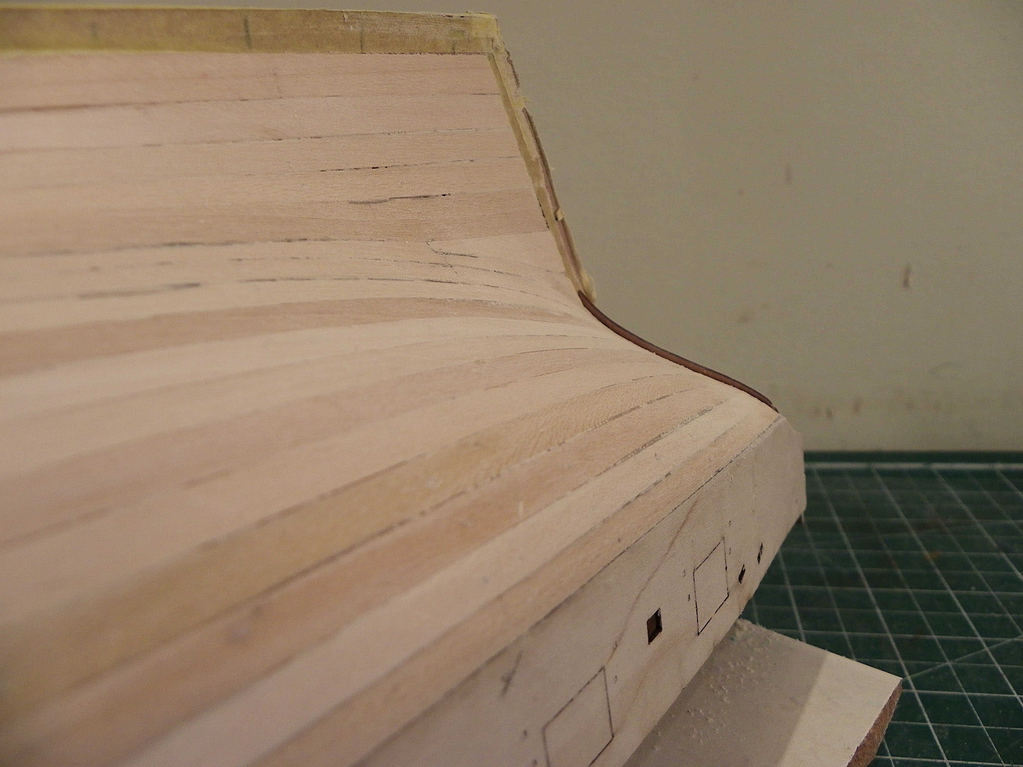
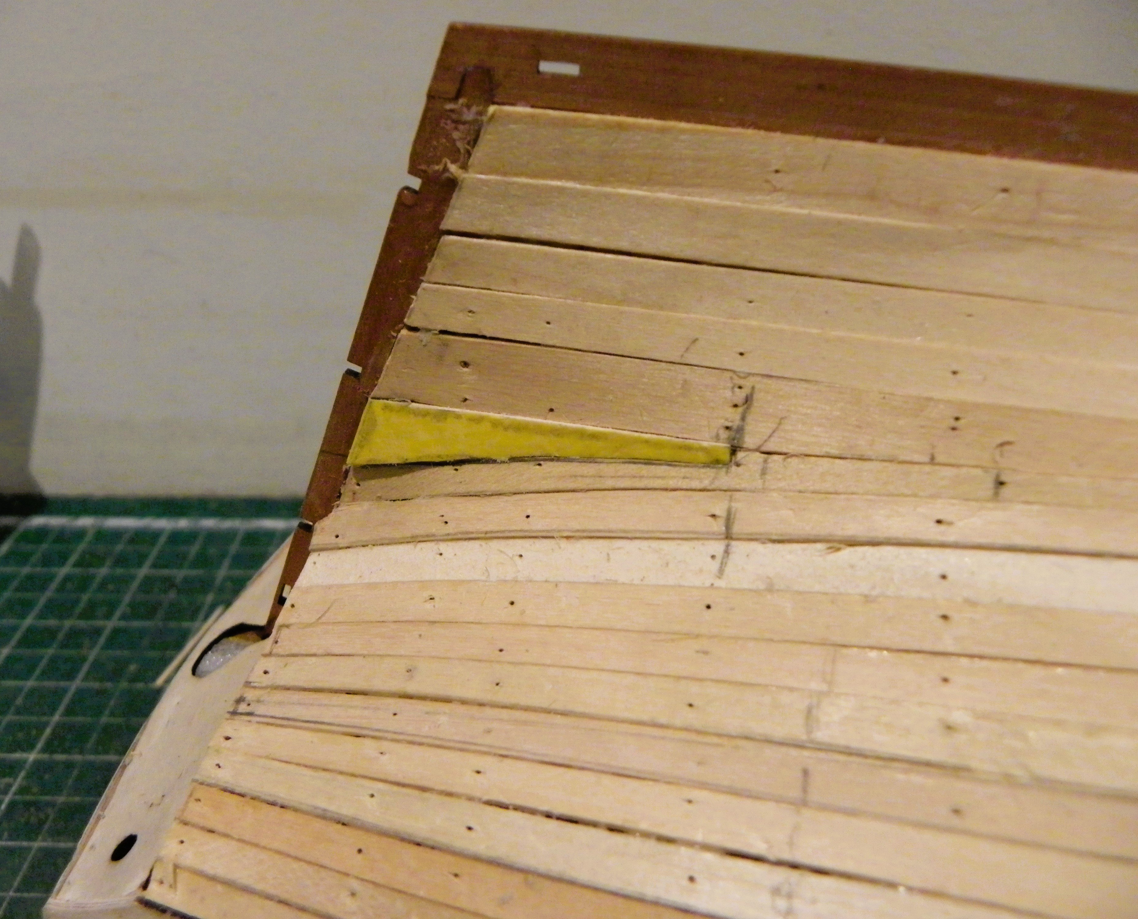
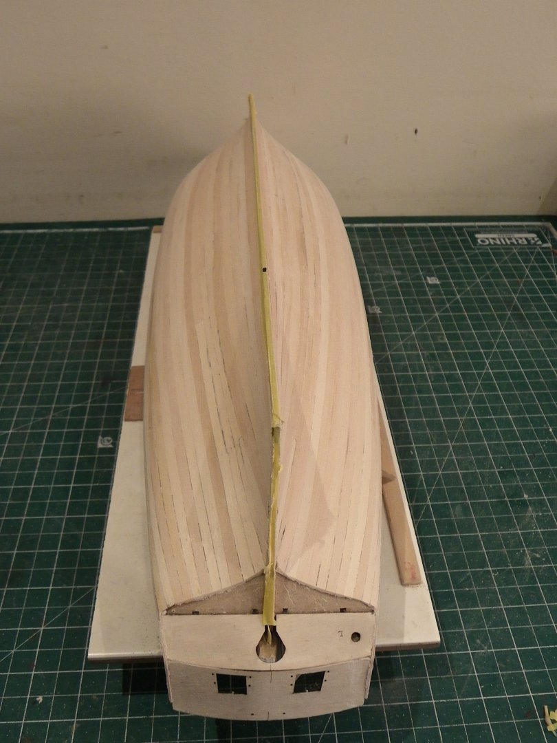
Post 25 The Lower Band. This is the remaining planking down to the keel. I have mostly used ca for plank fixing but I use Roket odourless from Deluxe Materials, a little more expensive than the basic sort but there is none of the breathing issues. Used on a slightly dampened plank it is very effective. 0199 0179 0200 I first fitted planks in continuation of the upper band down to the termination of the Square tuck. This comprised two strakes. 0180 0196 The rabbet for the hull timbers at the stem, formed by the outer stem pattern, works very well on Harpy. A great asset for bow planking, and providing a very neat finish. I did use a micro chisel to pare down the first planking layer where required, to allow a better fit. It also helped to thin down slightly the Pear plank where it entered the rabbet. 0194 I now need to re-mark the planking runs for the final push. B.E. 26/01/2025


- 332 replies
-
- 16
-
-
- Harpy
- Vanguard Models
- (and 1 more)
-
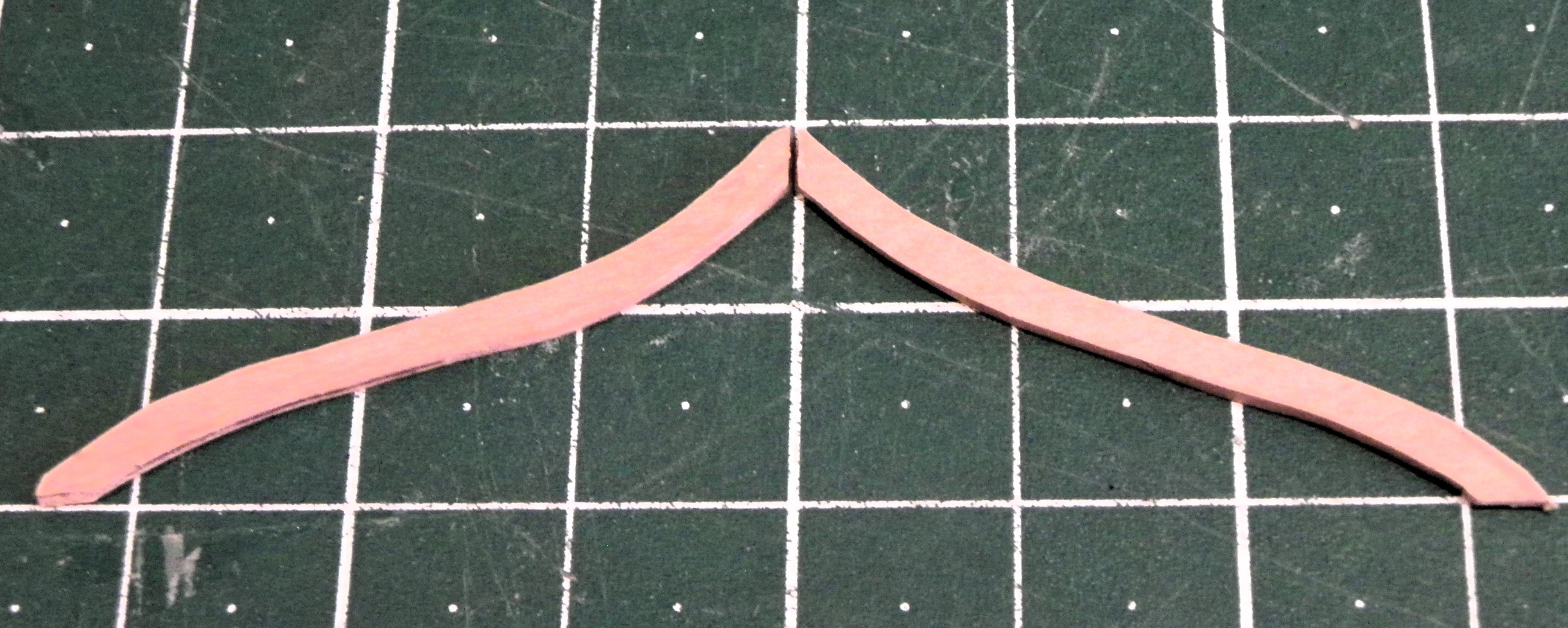
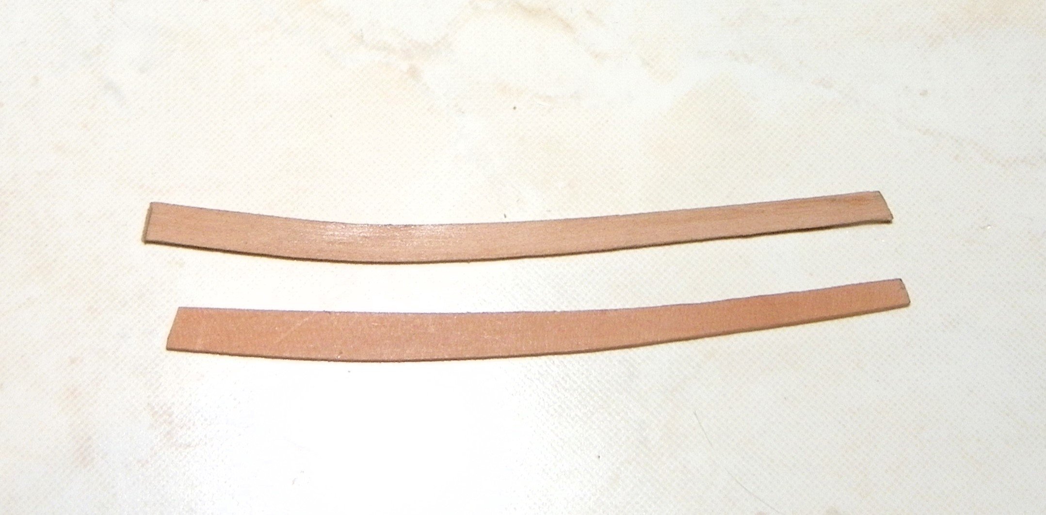
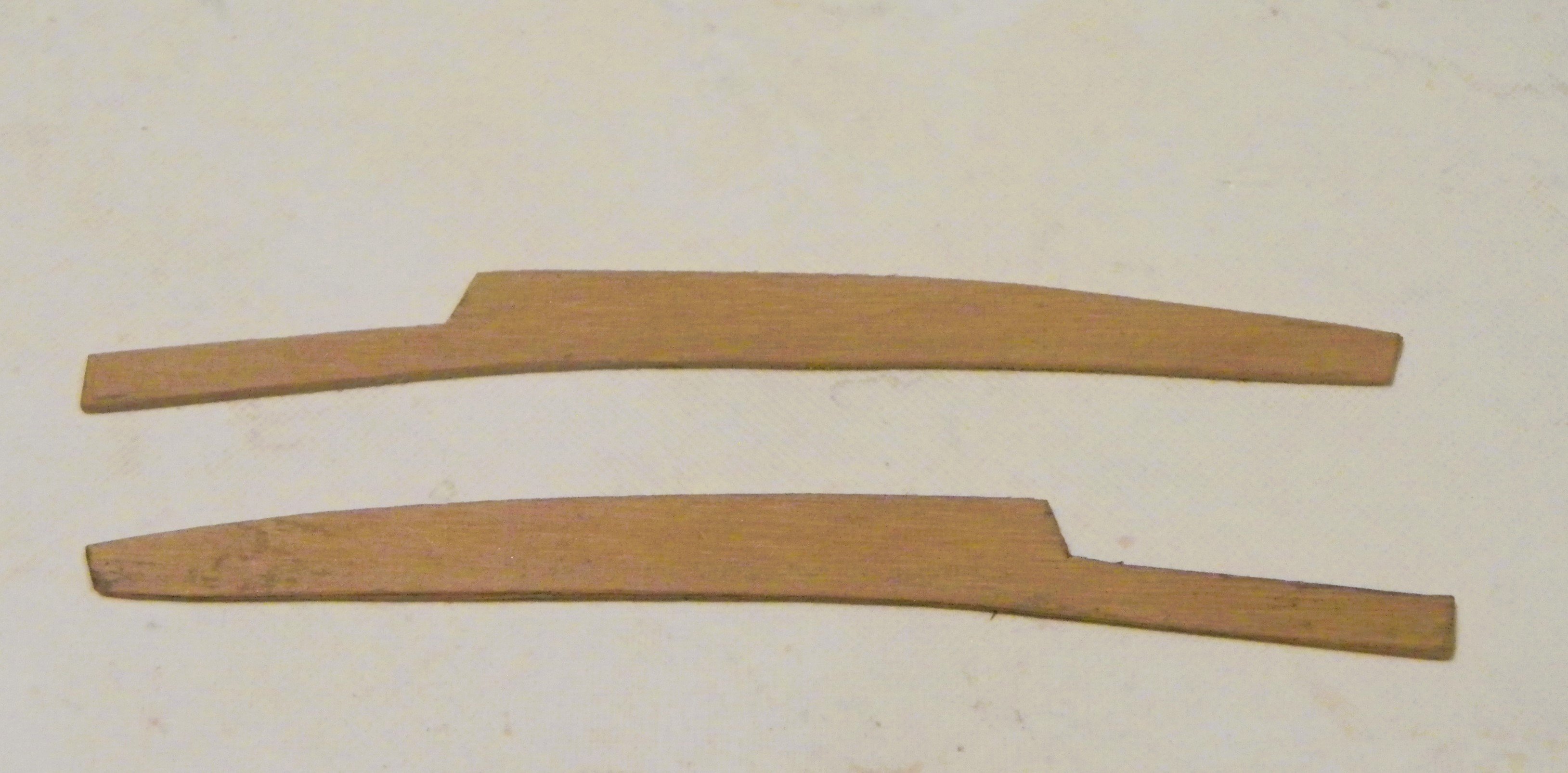
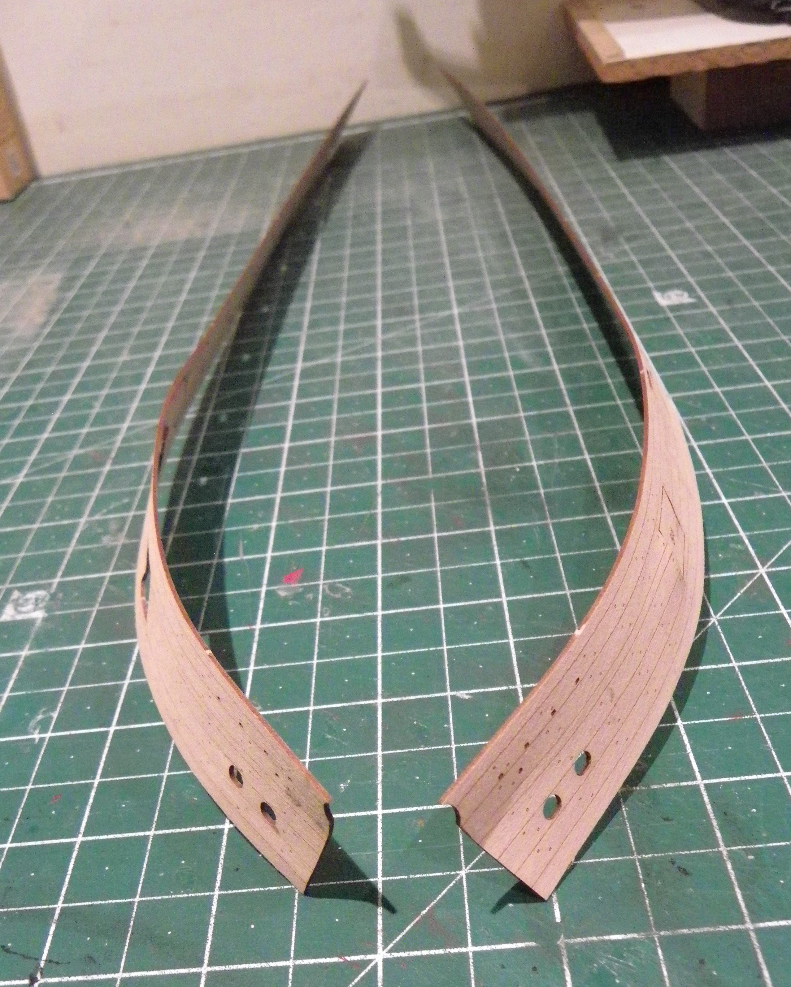
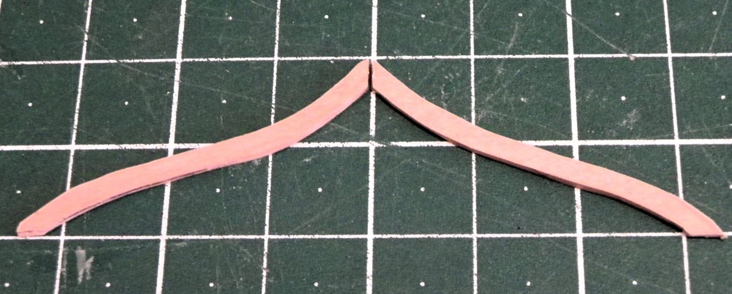
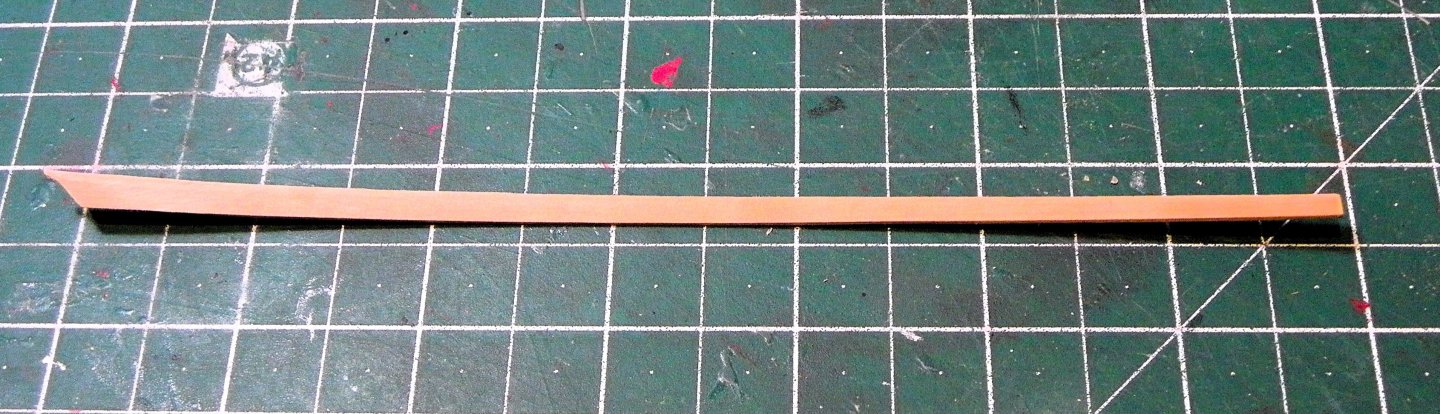
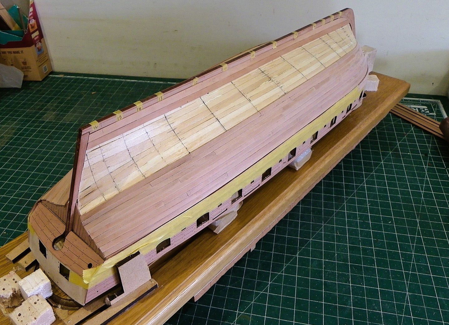
Post 24 Completing the first band. My first action is to address the question of increasing sny. I formed a plank in the normal way including the edge bend, and used this to shape a spiled version cut from 0.8mm fret. 0125 The two shapes. The lower one is the spiled plank which has a less concave upper line reducing the upward curve on the next strake to be fitted. I have now completed the first band. 0149 0150 0151 0152 0156 0170 0167 0165 0169 0175 At the stern either stealers or planks that broaden out from the mid ships point will be required. I may use a combination of both as I have broader strips of Pearwood. It is not a critical decision as I fancy coppering this hull, after completing two bare plank hulls. It has been some 14 years since I last coppered a hull (Pegasus) and it will keep me busy and extend the build time. B.E. 24/01/2025


- 332 replies
-
- 18
-
-
- Harpy
- Vanguard Models
- (and 1 more)
-
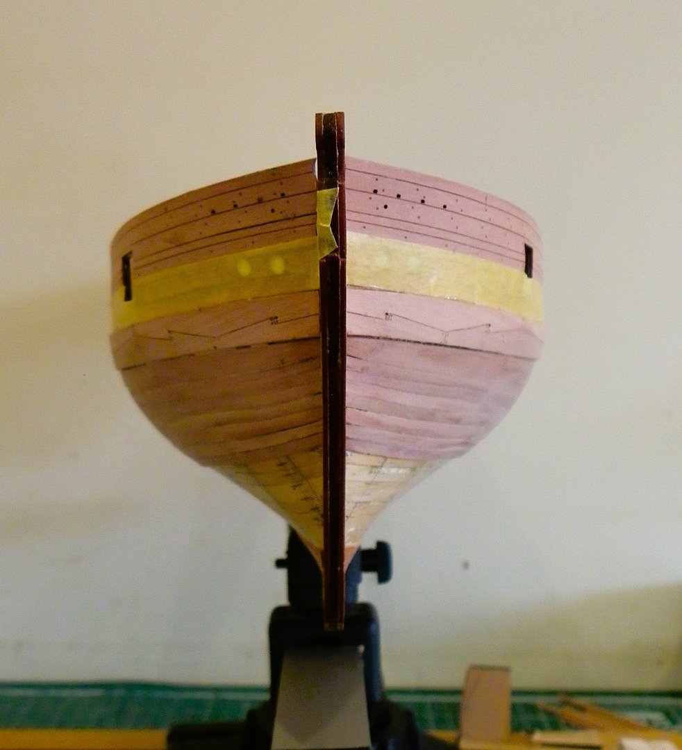
Hi Glenn, Sny is the curve of a plank as it rounds the bow. In this context it relates to the excessive upward curve of a plank where the centre is higher than the extremities. This is a common problem in the bow area and I recognise its development on my hull. Probably due to deficiencies in my lining off and or improper tapering, it occurs where the planks are edge bent as they round the bow, and strake upon strake, the effect is magnified. Rather than fetch the planking off I will attempt a fix in the next strake. B.E.
- 332 replies
-
- 4
-
-
-
- Harpy
- Vanguard Models
- (and 1 more)
-
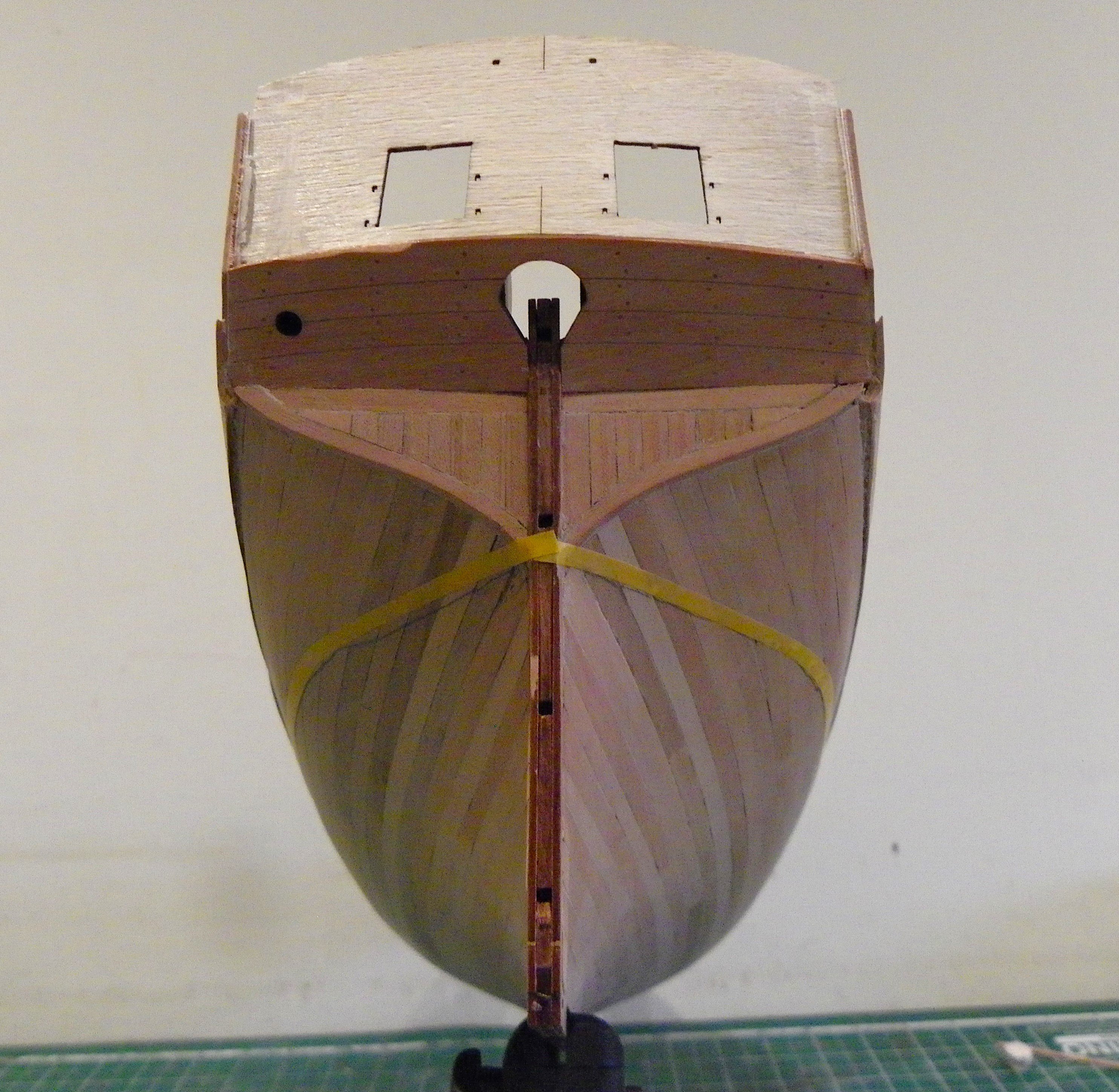
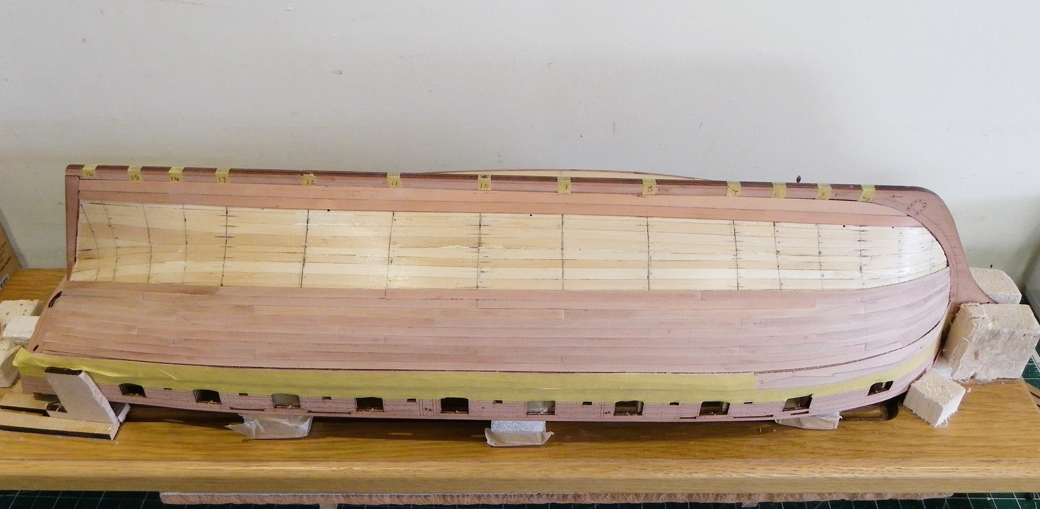
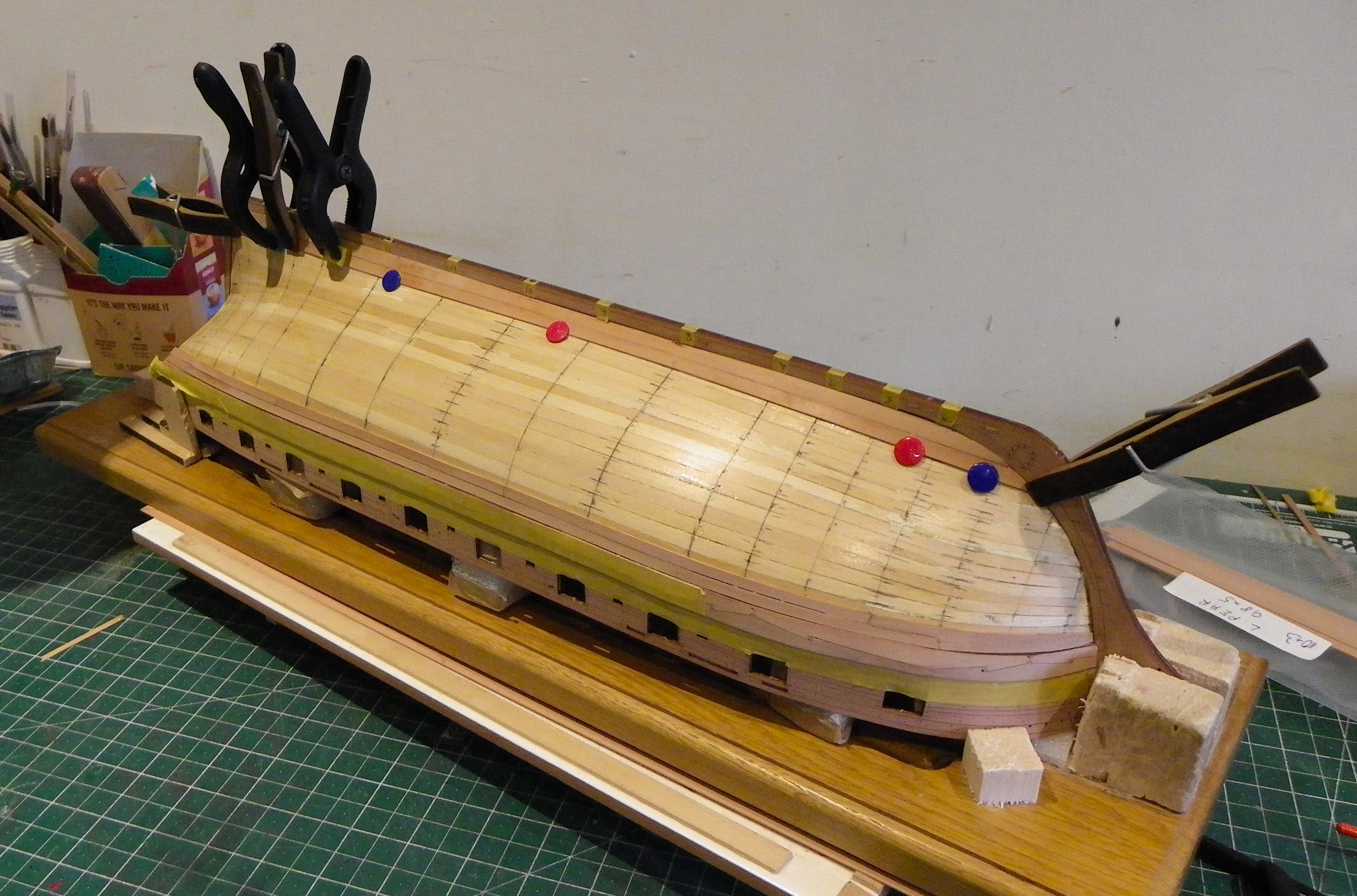
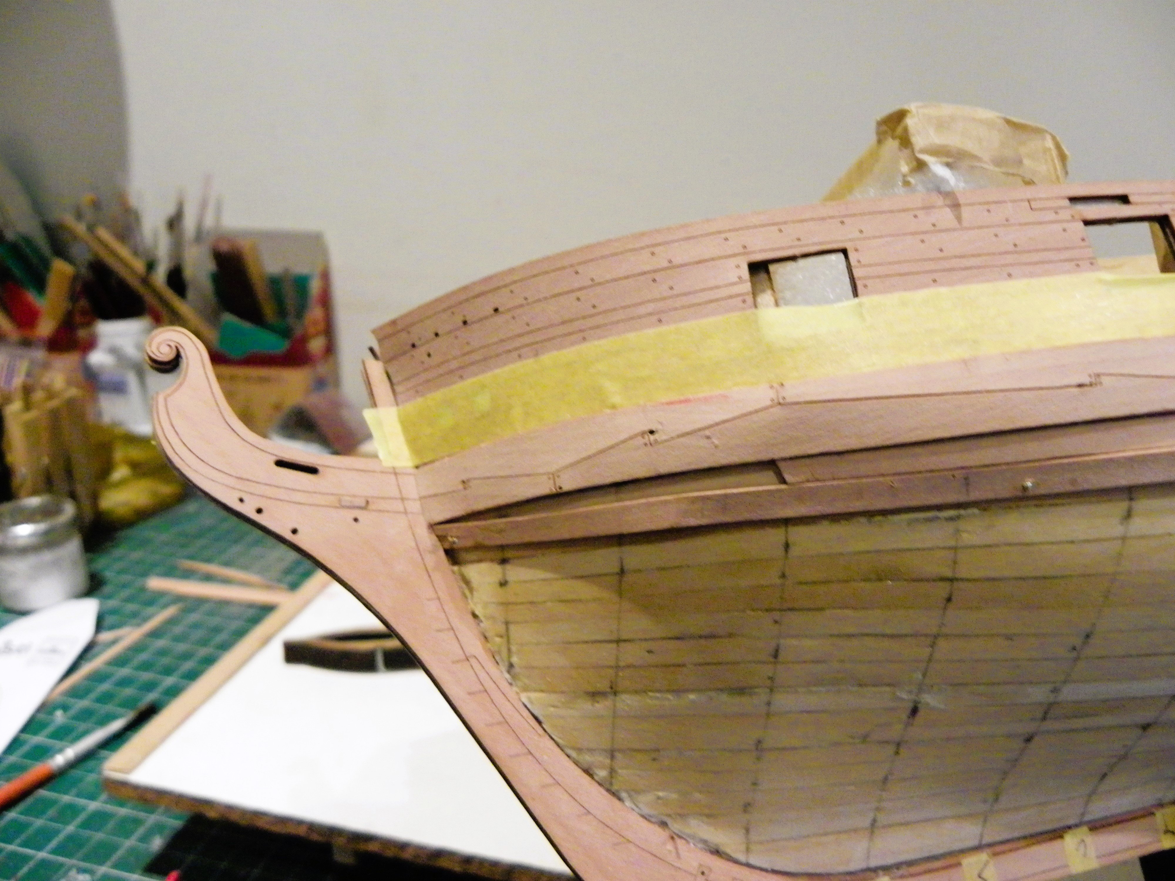
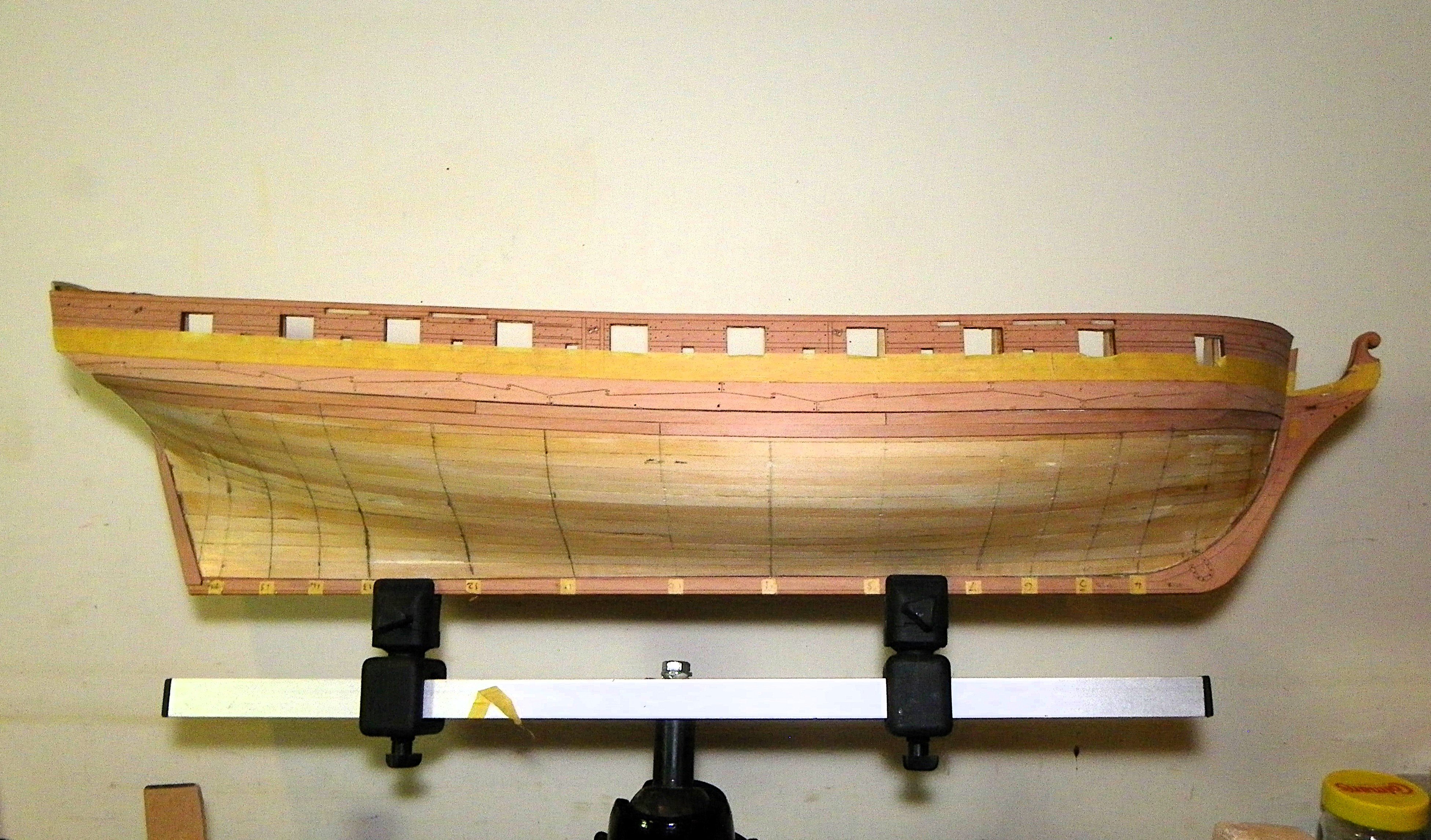
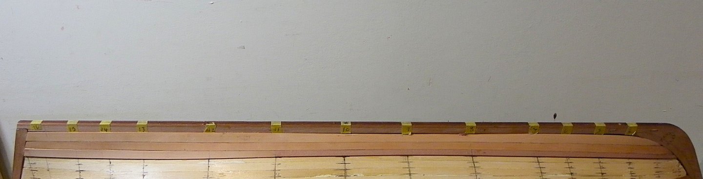
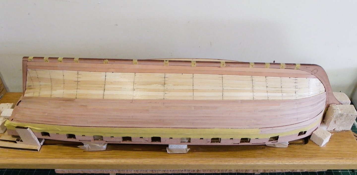
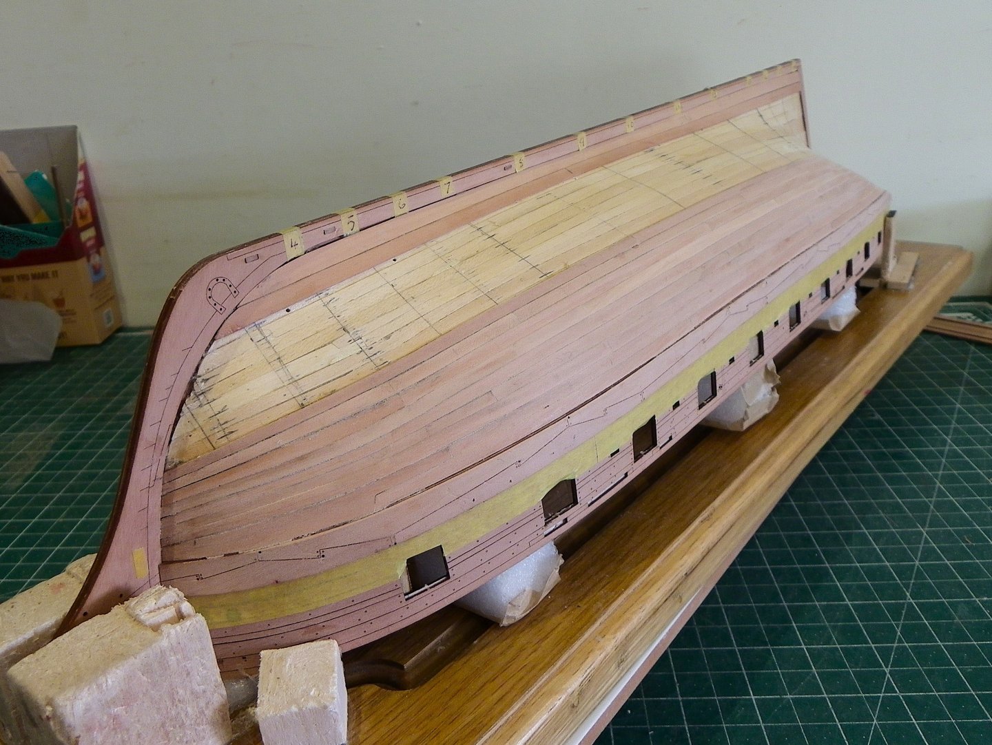
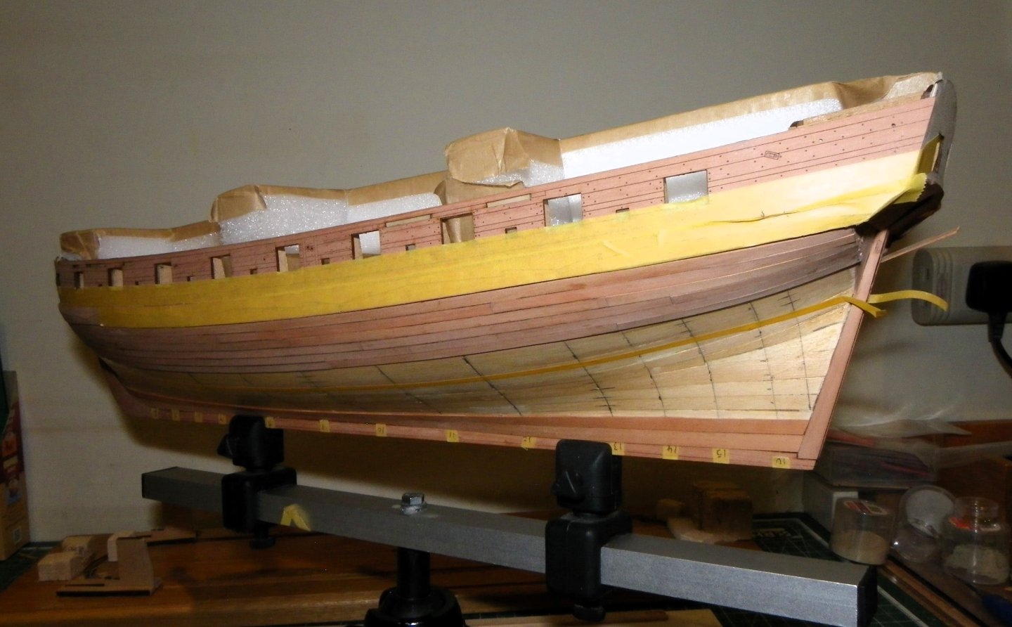
Post 23 The first band. I had already marked the stations on the hull and the next task is lining off. 0096 I have lined off at a point I hope takes me just below the waterline which results in seven strakes at midships Bulkhead 10 and the tape reflects this. I am never entirely happy with my lining off I can never quite decide if I’ve got the optimum line, so it inevitably involves tweaking as I go along. 0095 Each strake involves tapering, edge bending, and bevelling. I make one for each side before I fit either. 0110 At this point, four strakes below the Drop plank have been fitted. I can detect a hint of snying creeping in which I will need to attend to as it only gets worse and is never a good look on a model. 0113 0104 0106 I have maintained full width planks at the stern for this band but I can see as planking progresses wider planks or stealers will be required. There is an element of drag on this hull, which can be seen from the waterline level. 0115 I am using individual lengths of planks of around 140mm, with a minimum length of around 60mm. Apart from anything else this makes the fitting of planks easier, particularly when using ca. I’m not working to a specific pattern as I would with deck planking, but I am careful not to have butts meeting or too close to those on adjacent strakes. 0116 0118 0122 In the next plank to be fitted I will tweak the sny out of it. Onwards, B.E. 23/01/2025


- 332 replies
-
- 15
-
-
- Harpy
- Vanguard Models
- (and 1 more)
-
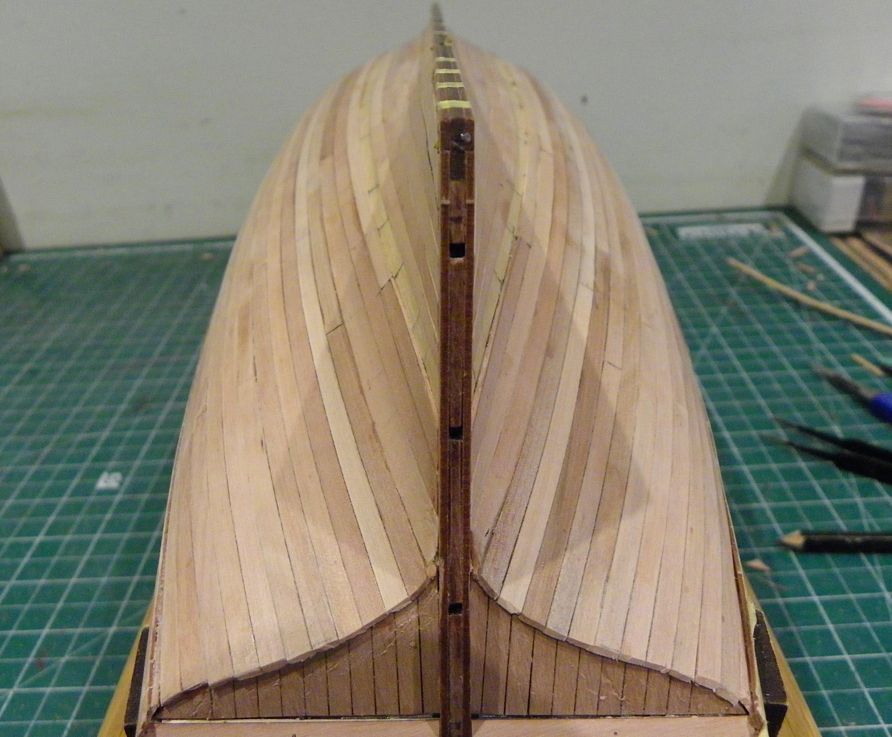
Thanks John, only two strakes down to me, it gets a bit more tricky from this point on. Post 22 Planking continues. Two strakes including a drop plank at the bow have been fitted below the wale. This should help reduce any crowding at the bow as planking proceeds. I now attend to the Garboard Plank. 0069 0073 I have decided to use a 6mm board. This is followed by a 5mm plank which takes care of the planking at the bottom end of the prow. 0075 Where I can I do prefer to use pva rather than ca. For this second plank I find use of drawing pins is a good method to secure the plank during glue set. I start a drill hole in the lime planking to avoid too much pressure on the first planking. 0088 0080 0082 0087 0091 I now have a set space equating to (14) 4mm planks at midships plus an additional 1mm. This is of little relevance at this point as the spacings will be re-drawn several times before the planking is completed. 0093 I am intending to plank a first band down to just below the waterline around (6) planks depth fore and aft. For these I will reserve the best of the colour matched planks. Onto lining off. B.E. 21/01/2025


- 332 replies
-
- 24
-
-
- Harpy
- Vanguard Models
- (and 1 more)
-
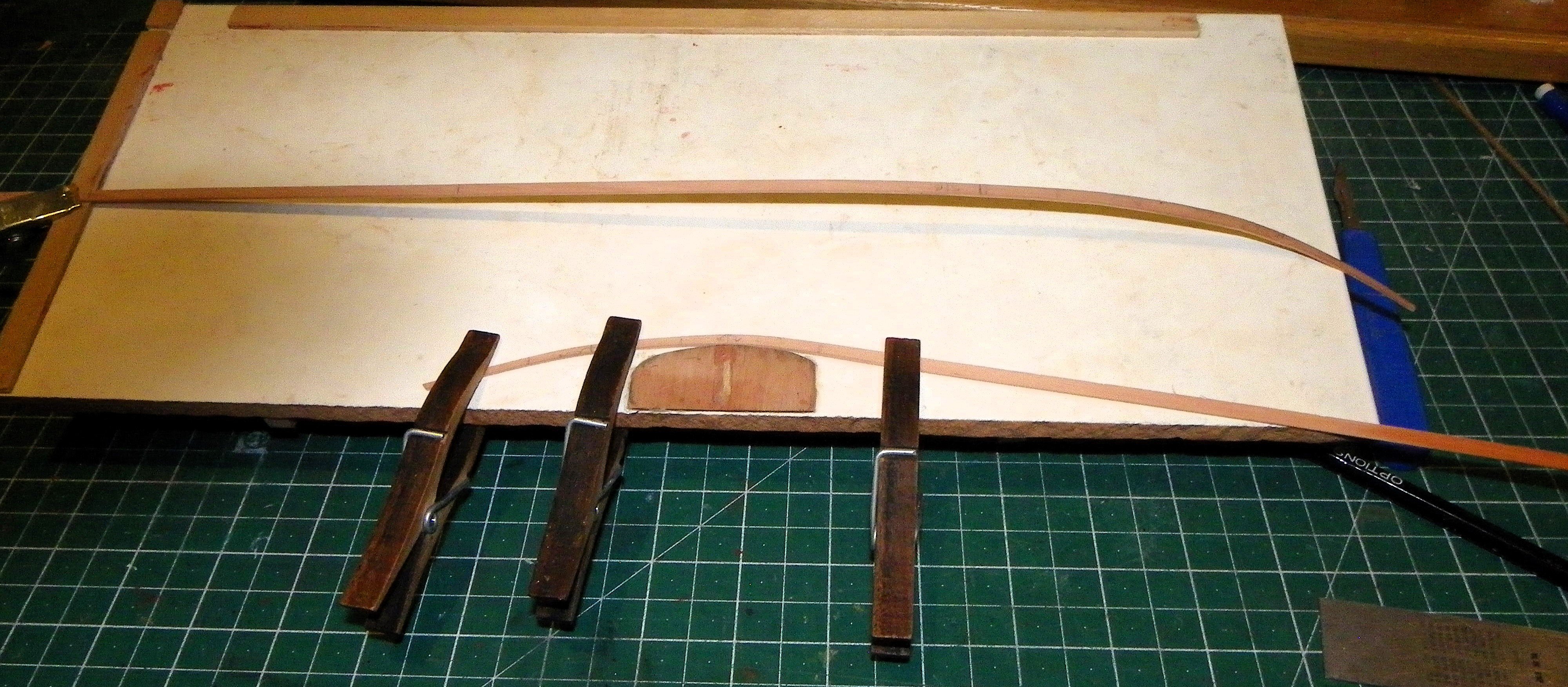
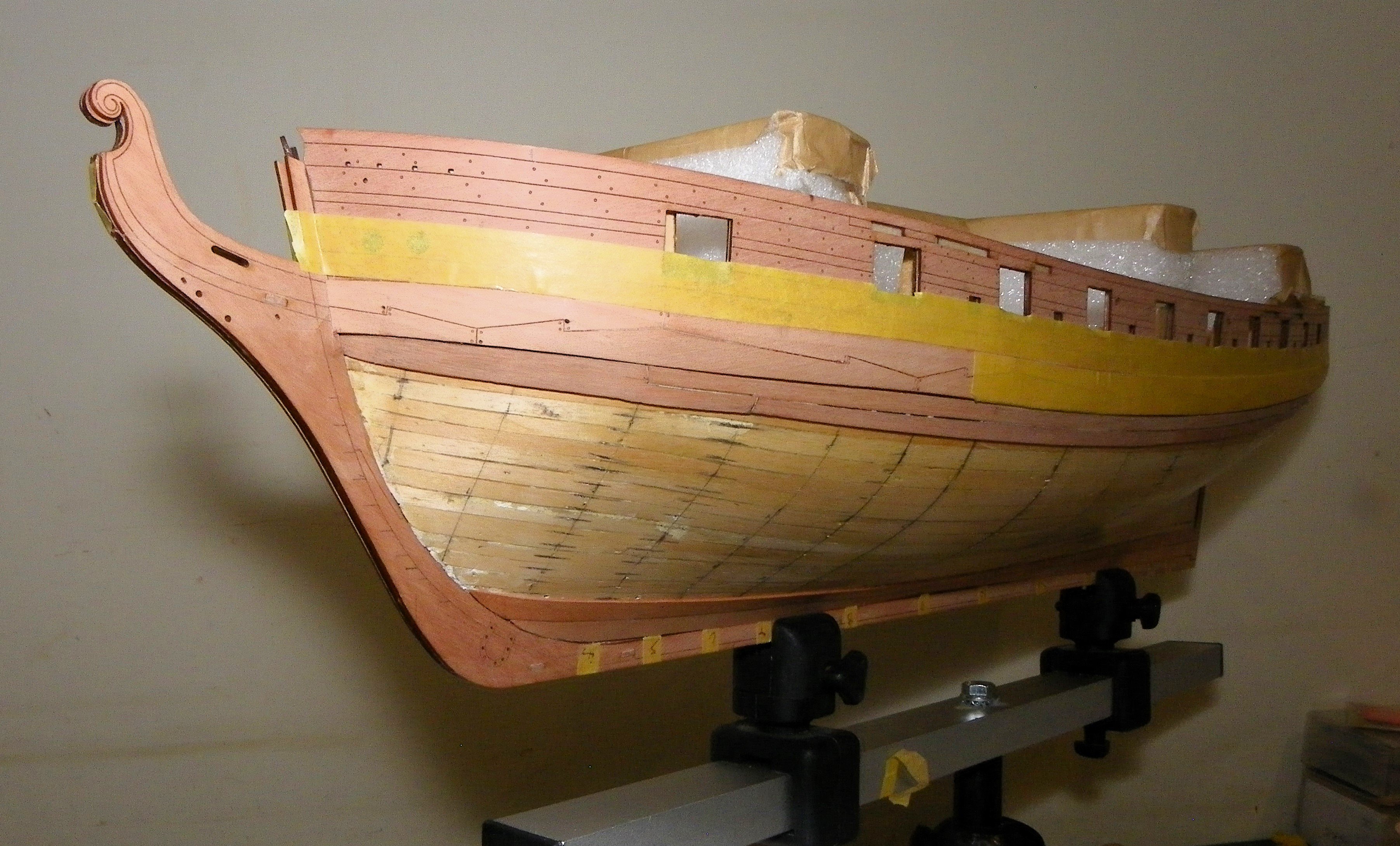
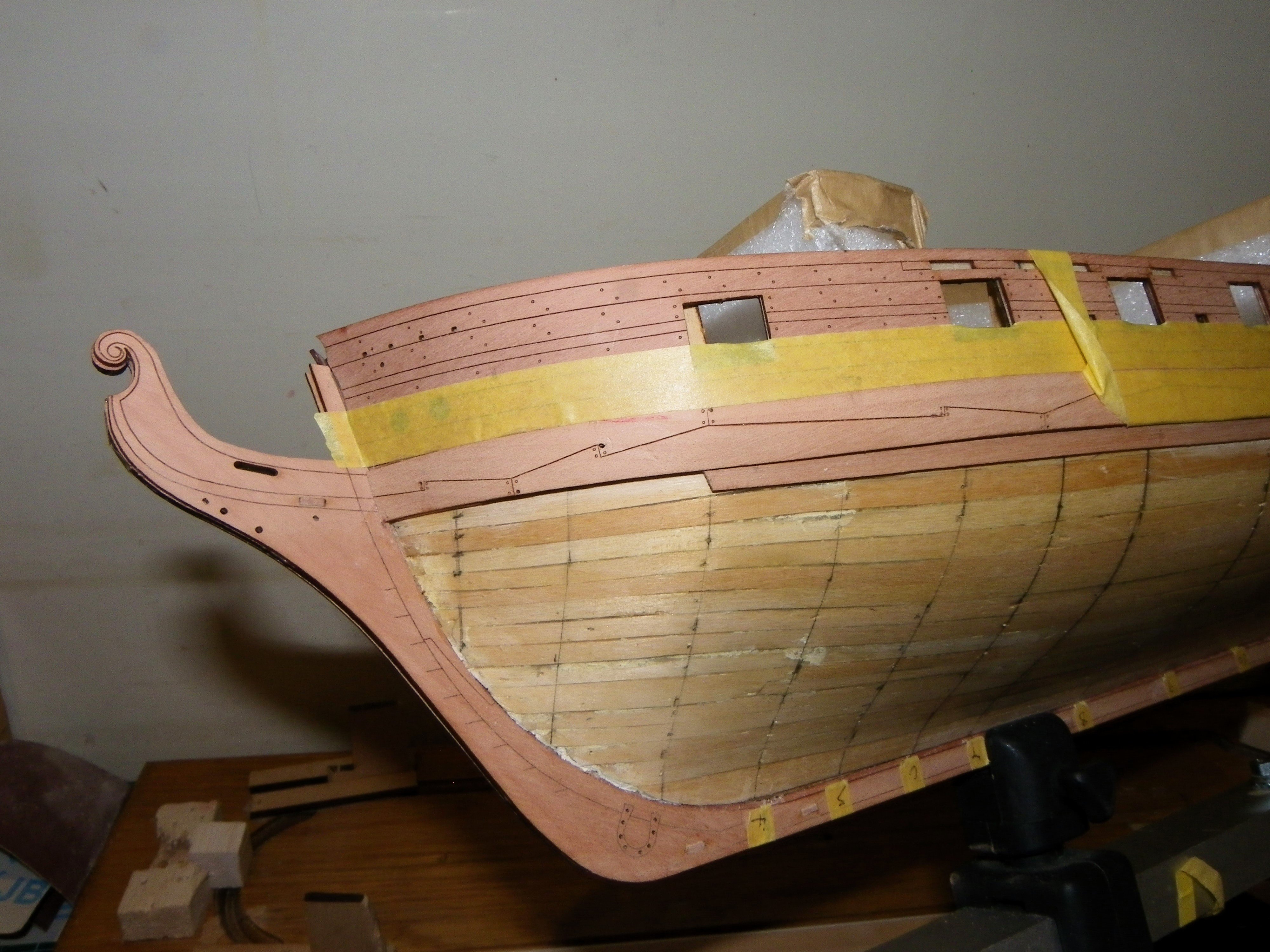
Post 21 Pearwood Planking I begin with making a Drop plank to fit directly below the wale at the bow. Above and running into the drop plank is a plank that runs the remainder of the way along the hull also directly below the wale. 0028 This plank I fit first, it terminates at the third bulkhead with a tapered width of 3mm. It then runs at full width to the stern. 0032 A temporary plank is run beneath to gauge the bottom line of the Drop plank. 0033 With this in place a pattern can be made for the Drop plank. This also tapers to 3mm at the stem, butts against the plank above it on its topside, and runs beneath it with a tail to bulkhead four. 0036 The patterns are cut out of some spare Pear fret. 0035 Dry fitting the drop. 0040 0053 After a lot of tweaking and dry fitting they are glued into place. 0062 0063 My next job will be to check the remaining strake numbers required and size up the Garboard Strake. B.E. 18/01/2025


- 332 replies
-
- 26
-
-
- Harpy
- Vanguard Models
- (and 1 more)
-
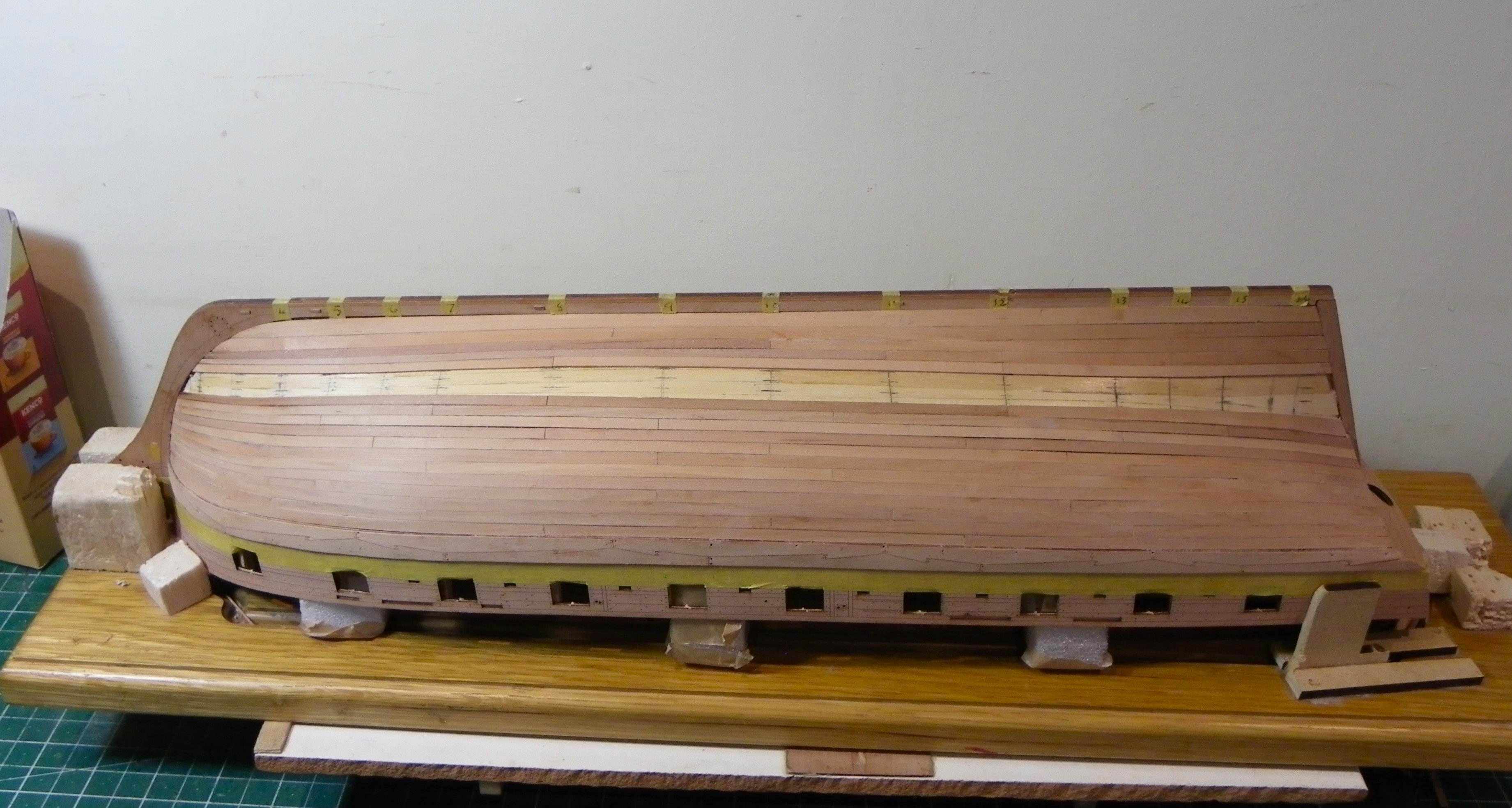
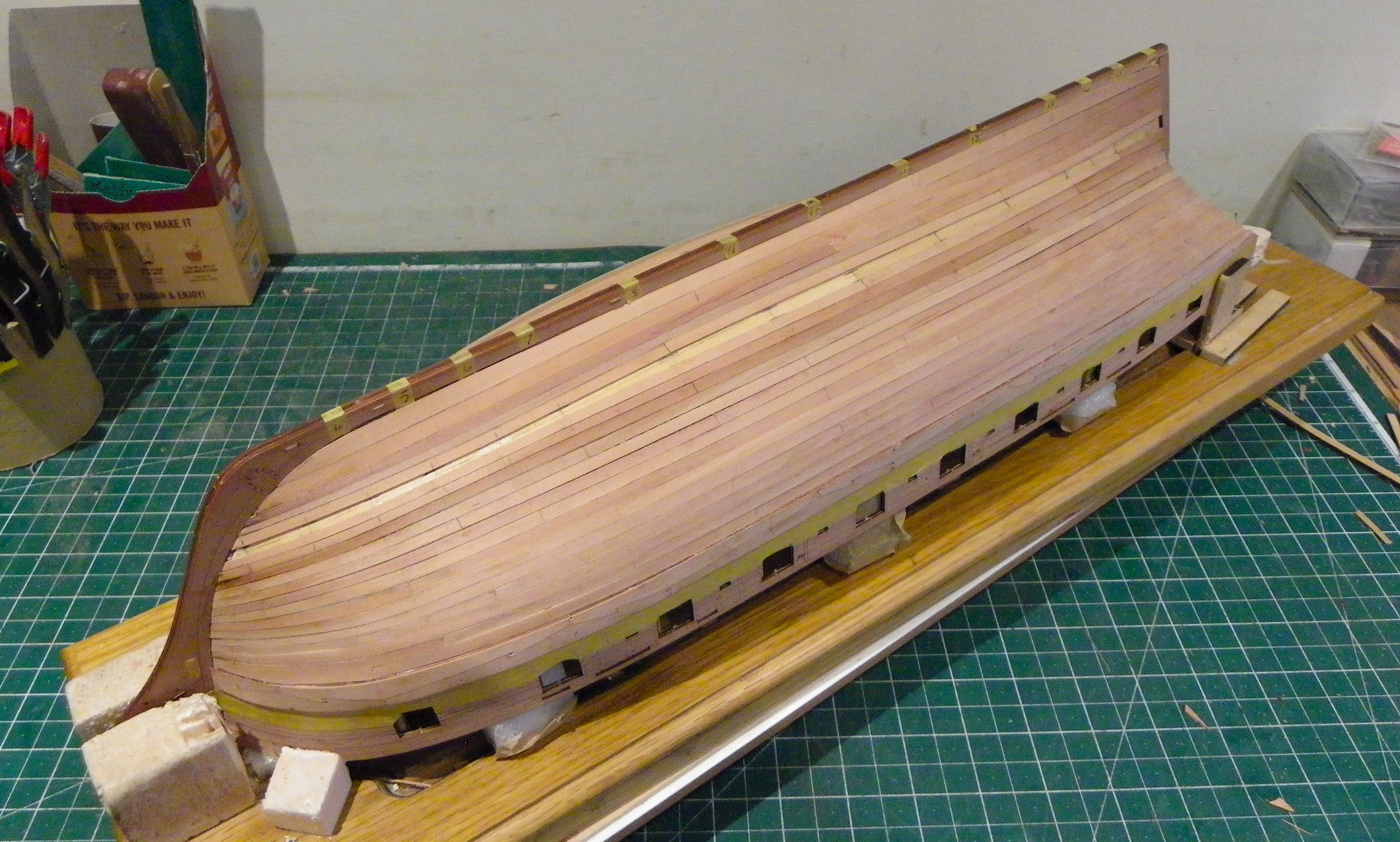
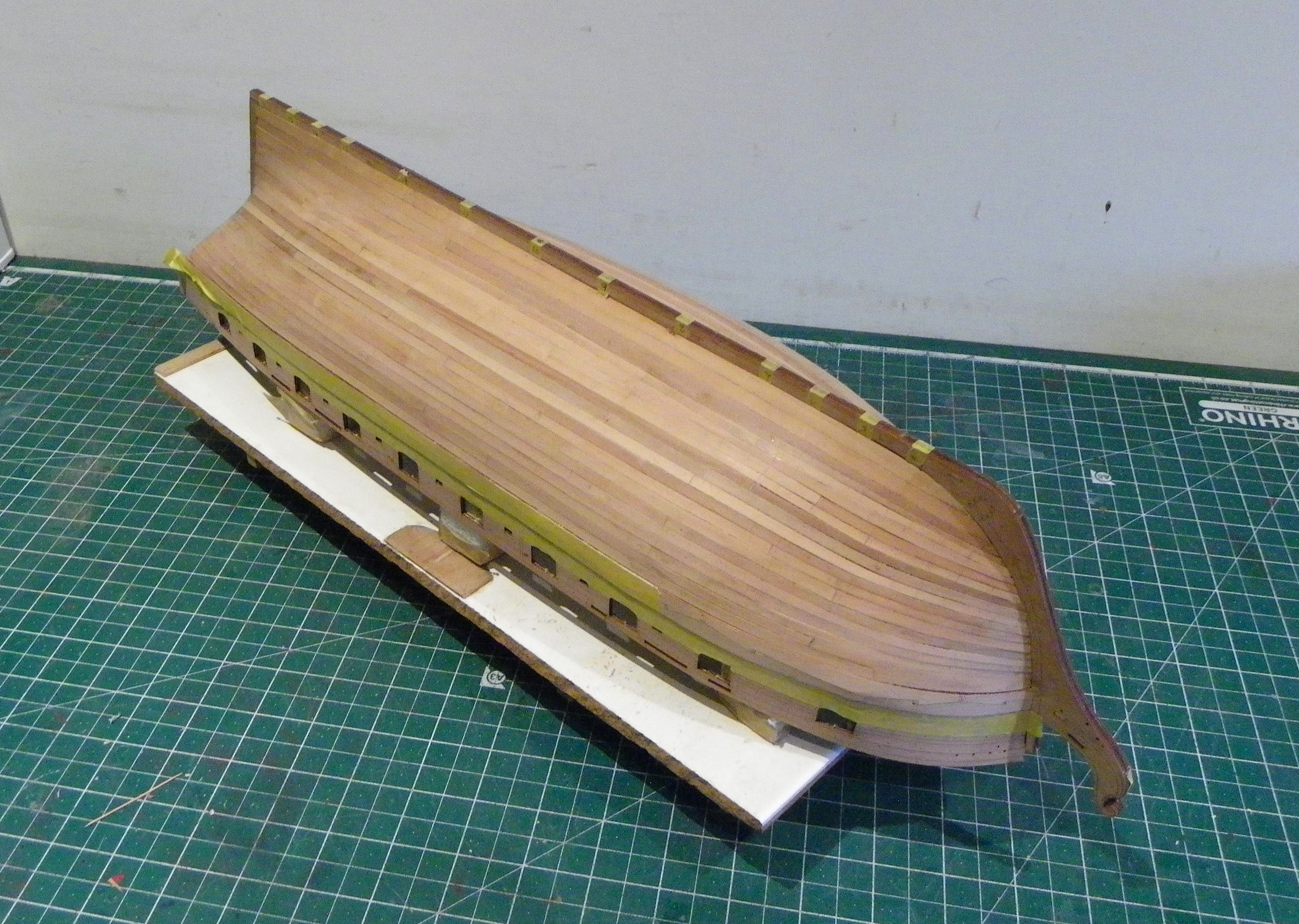
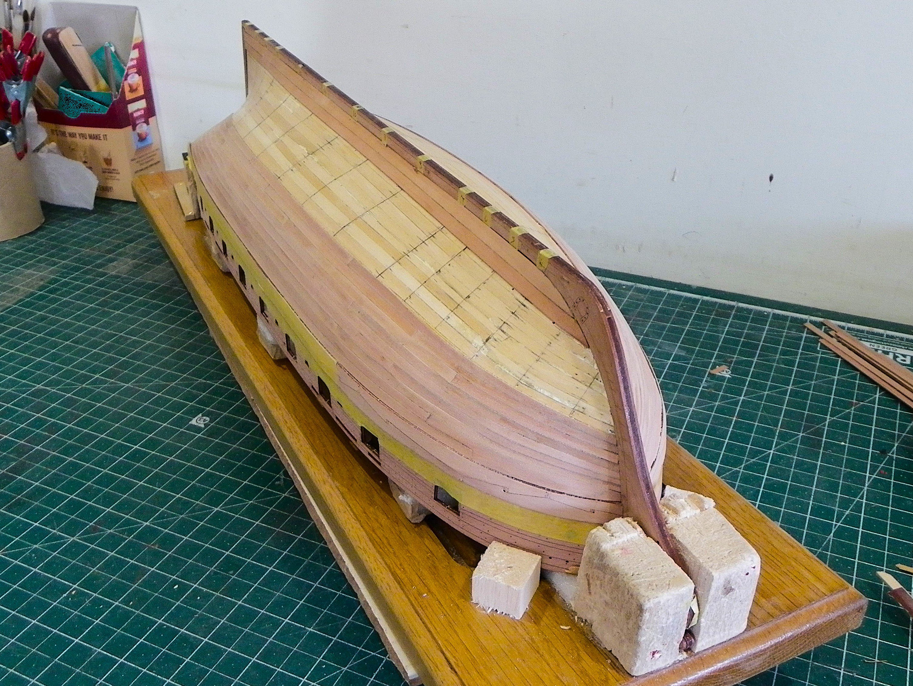
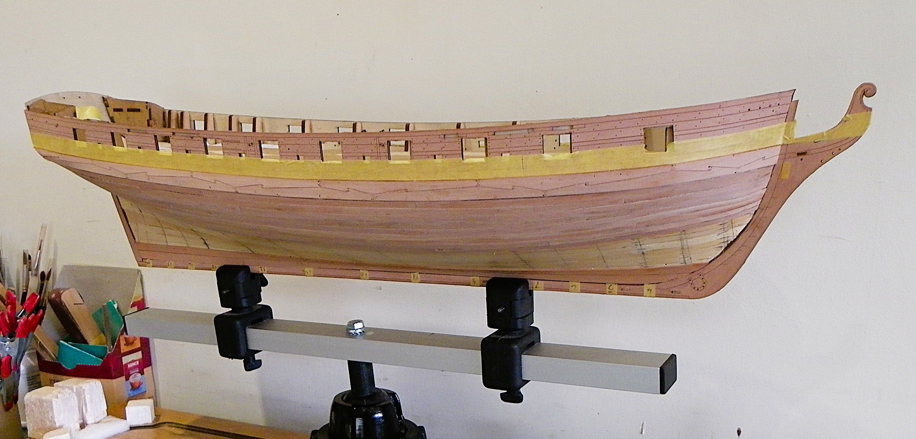
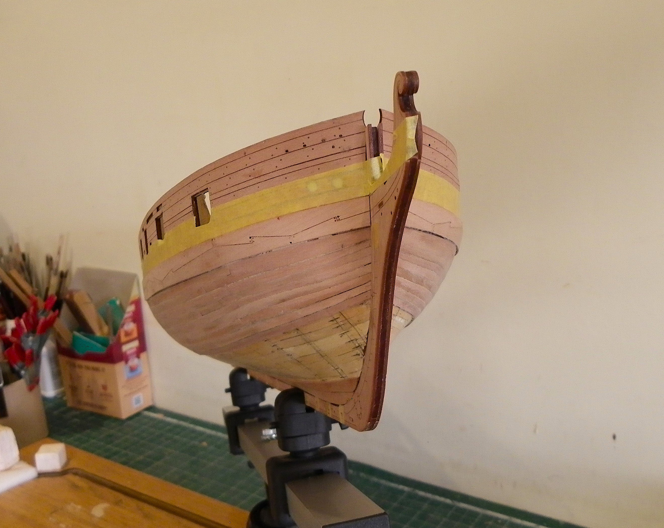
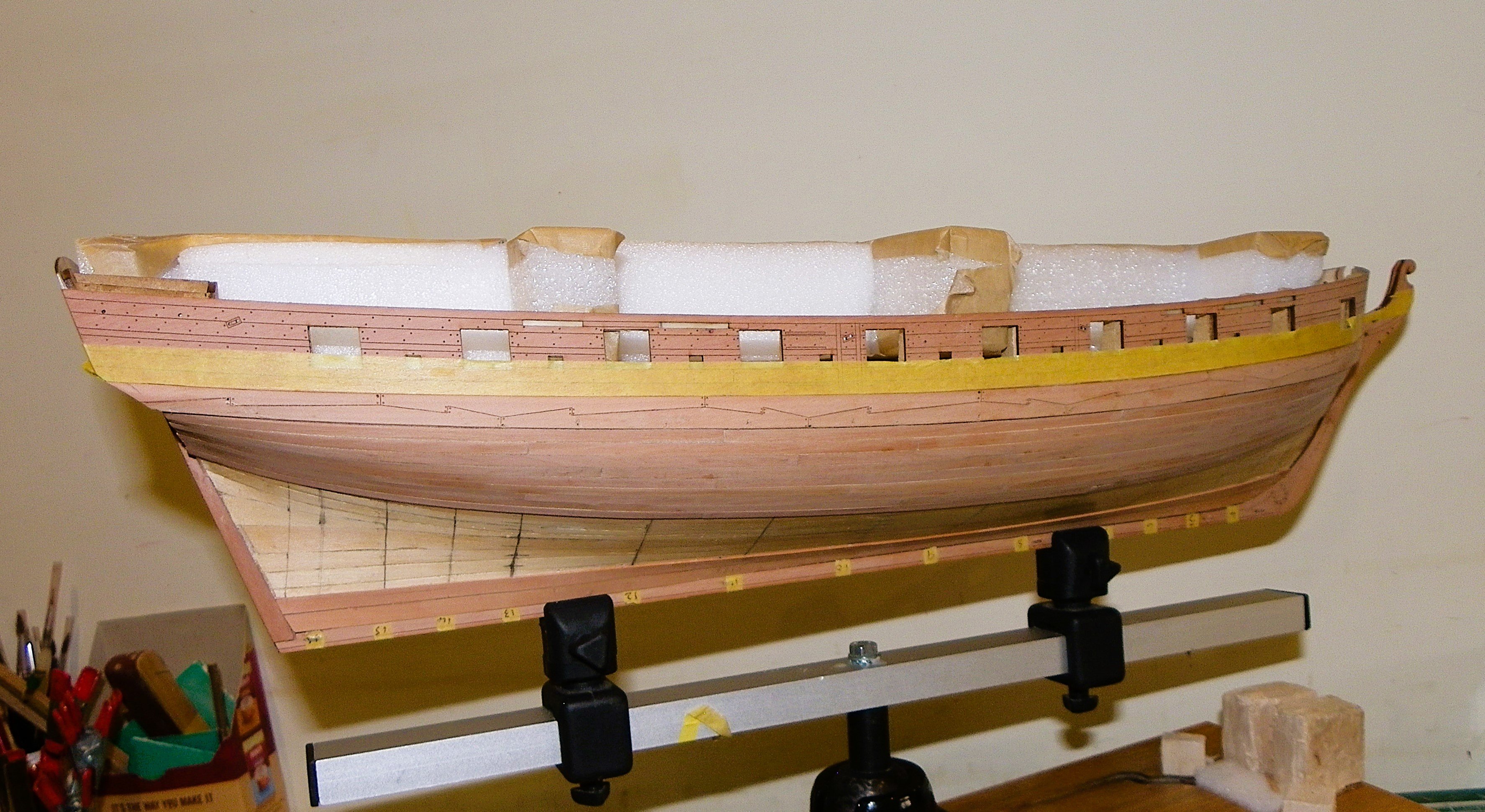
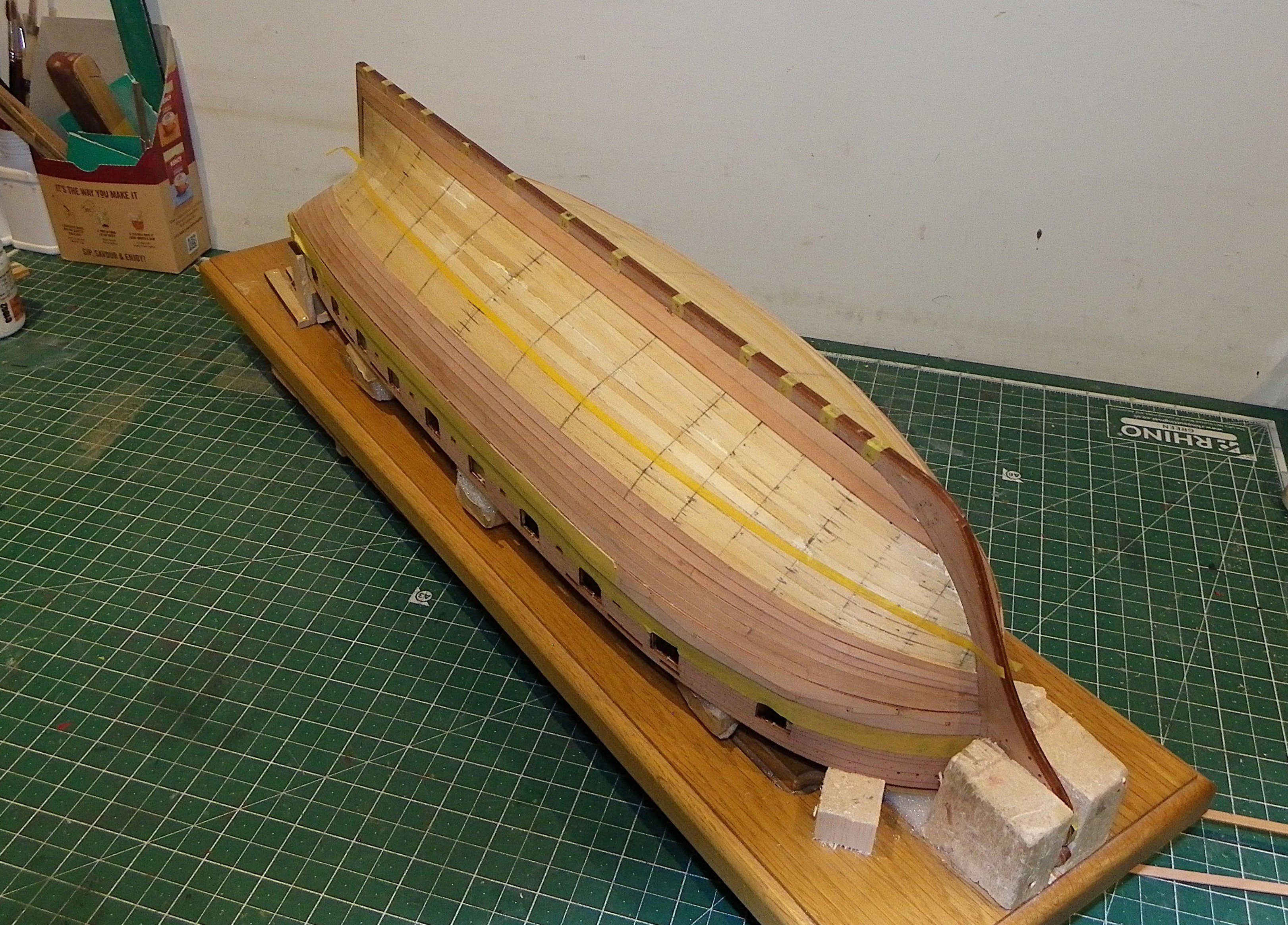
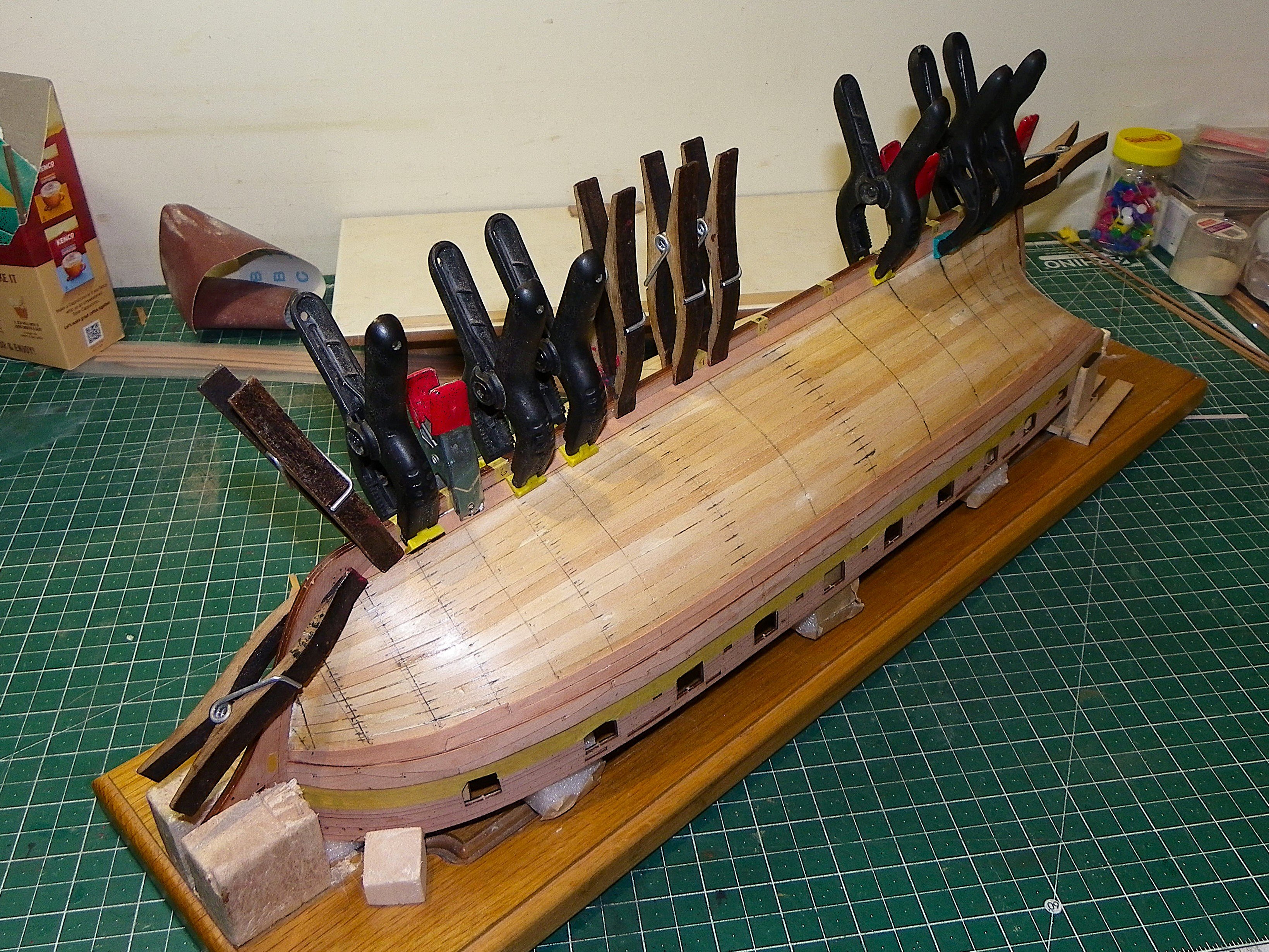
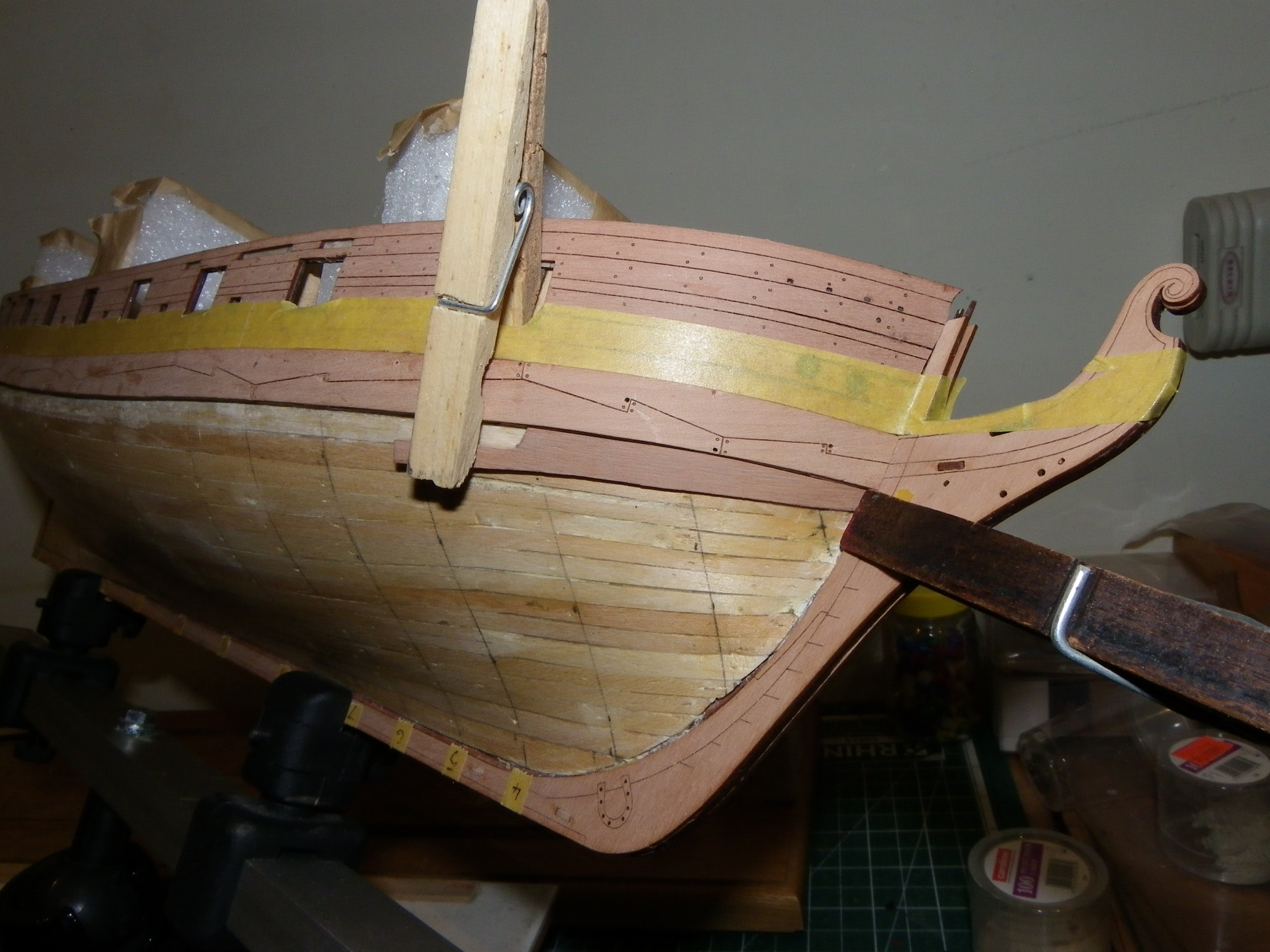
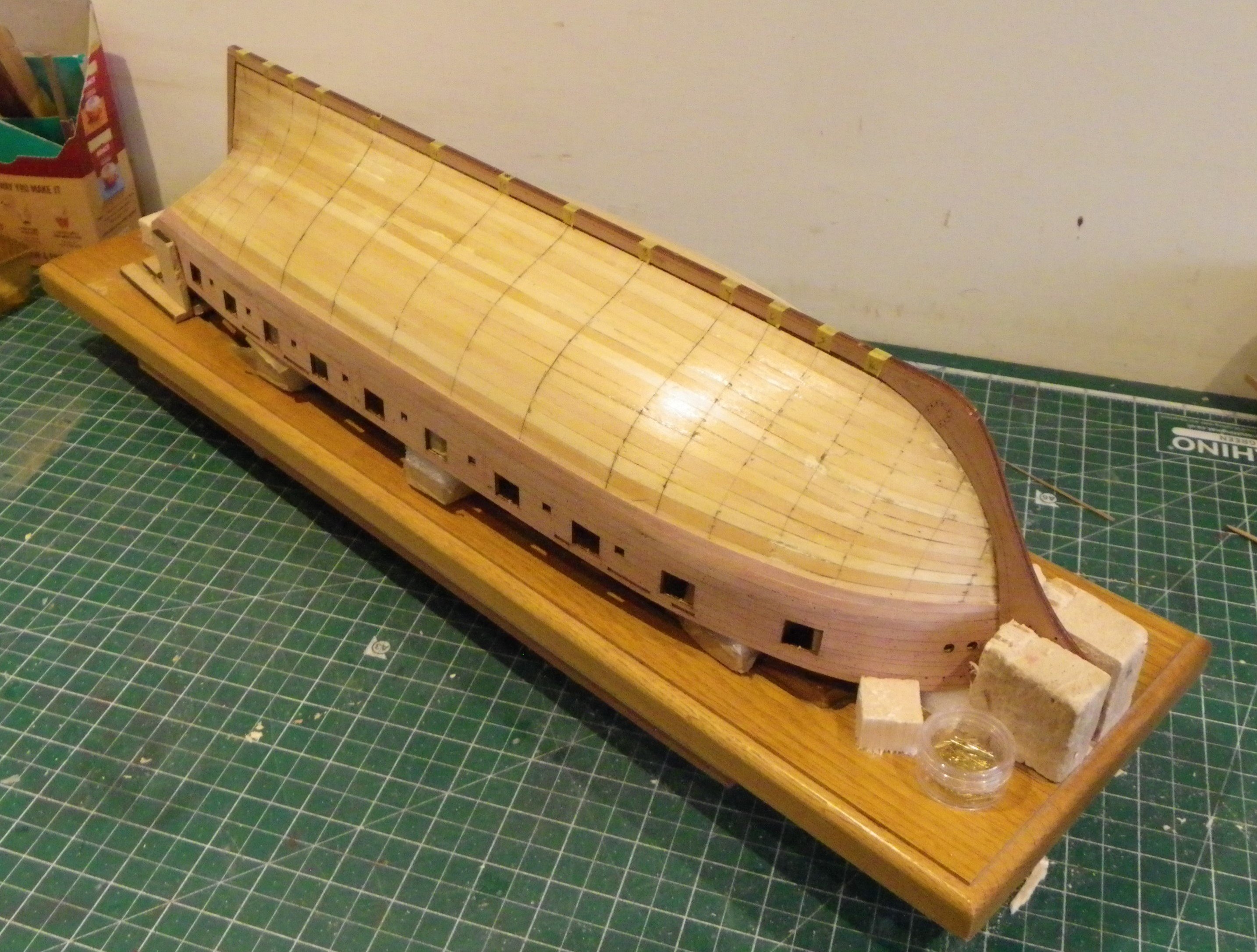
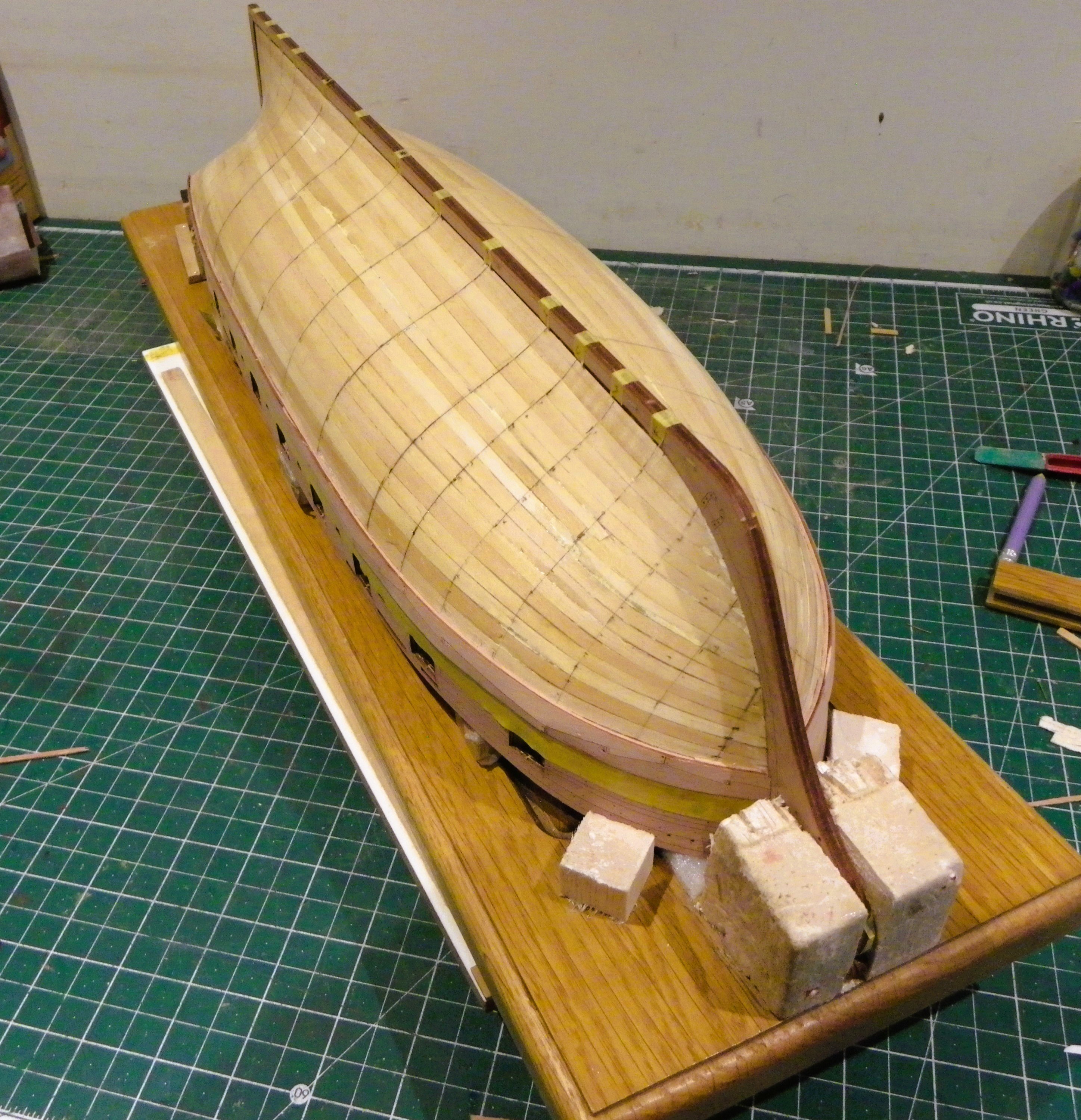
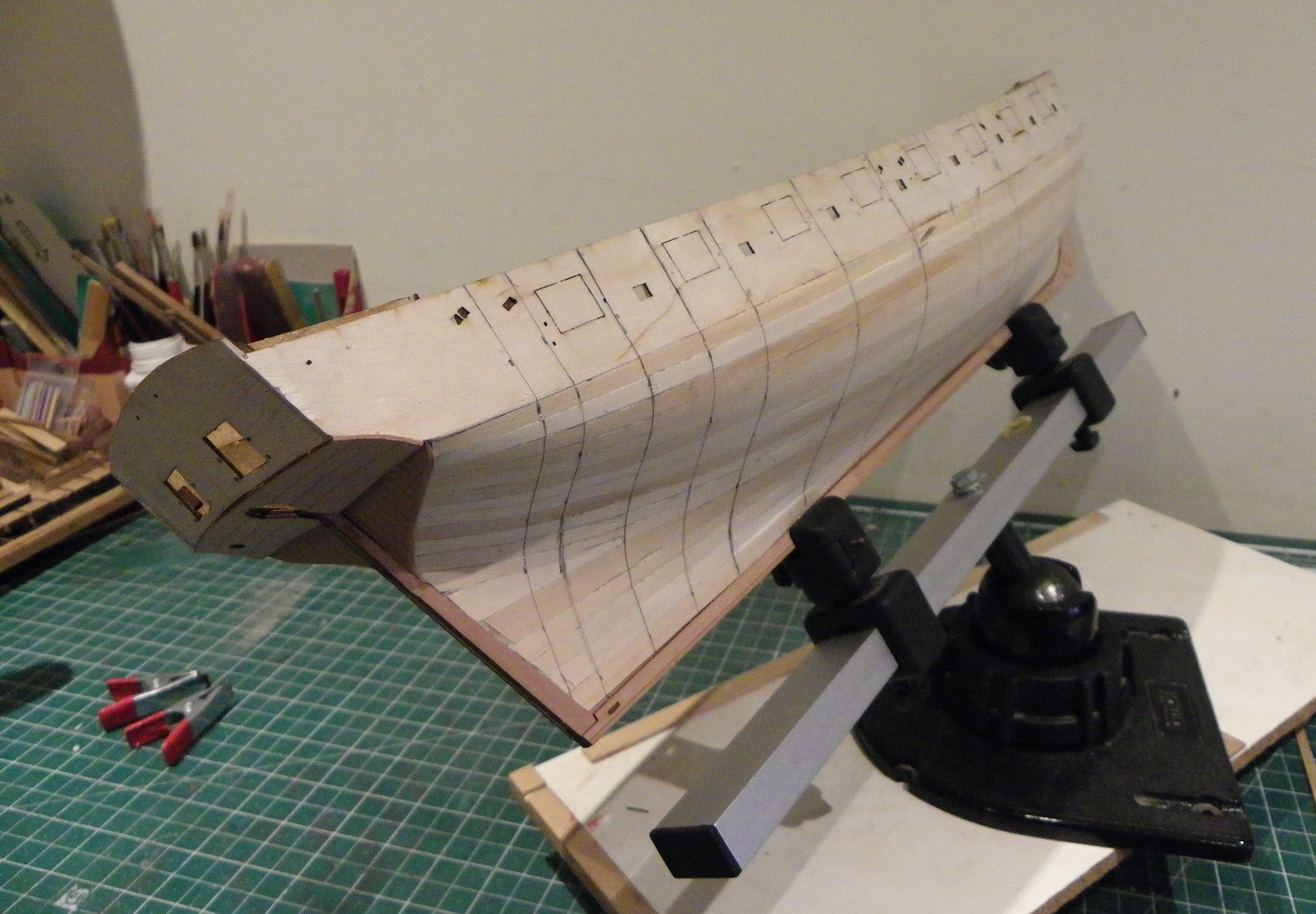
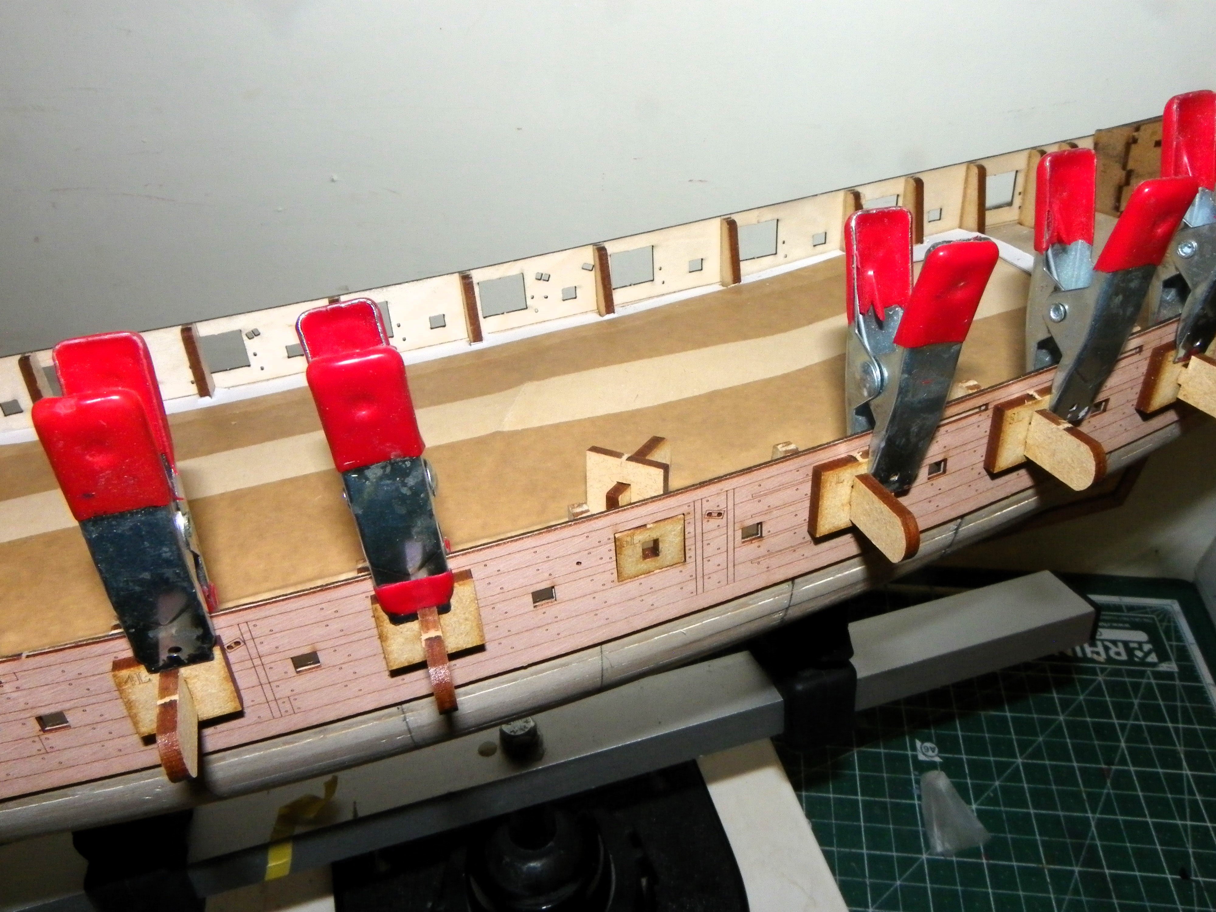
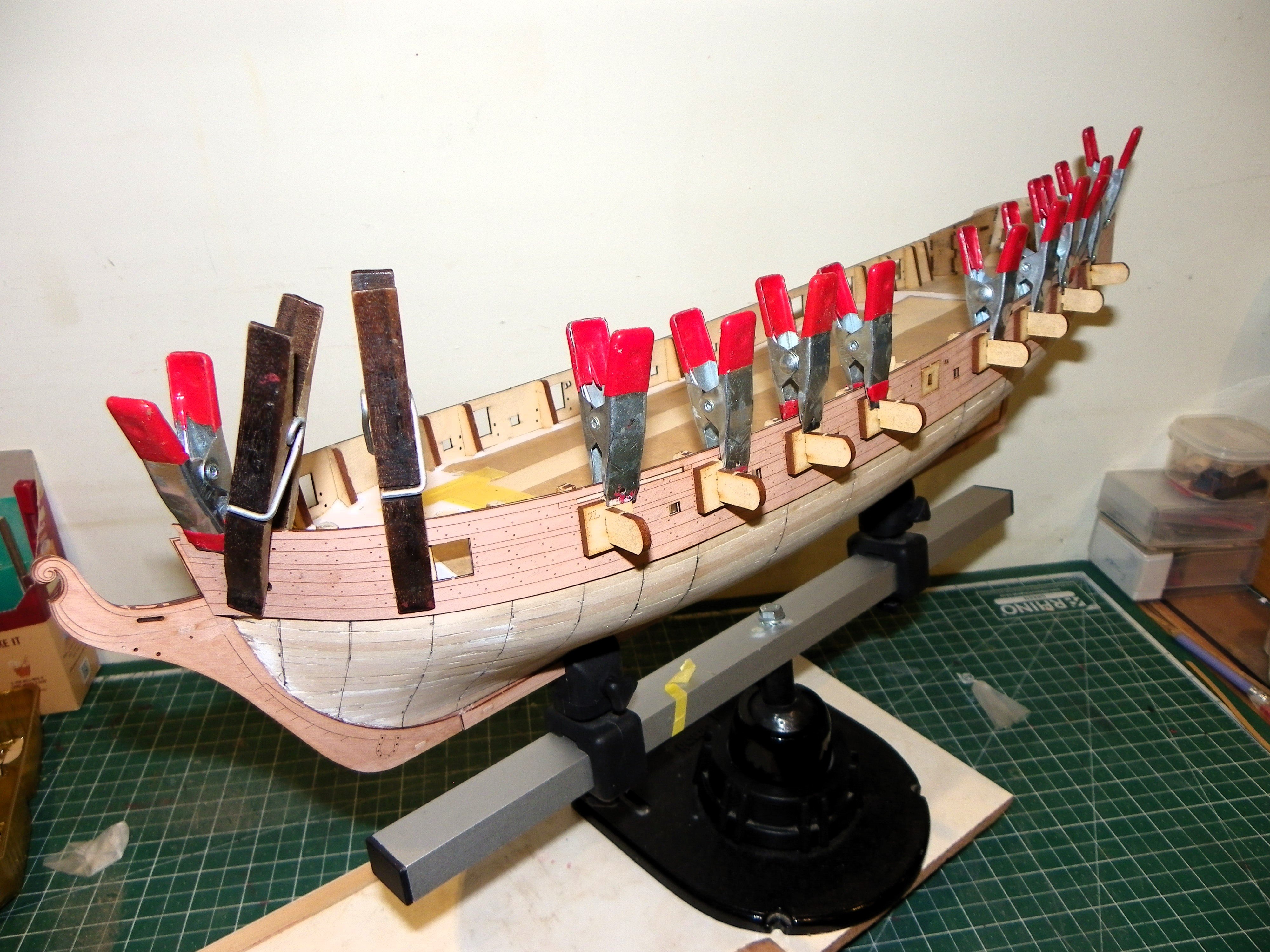
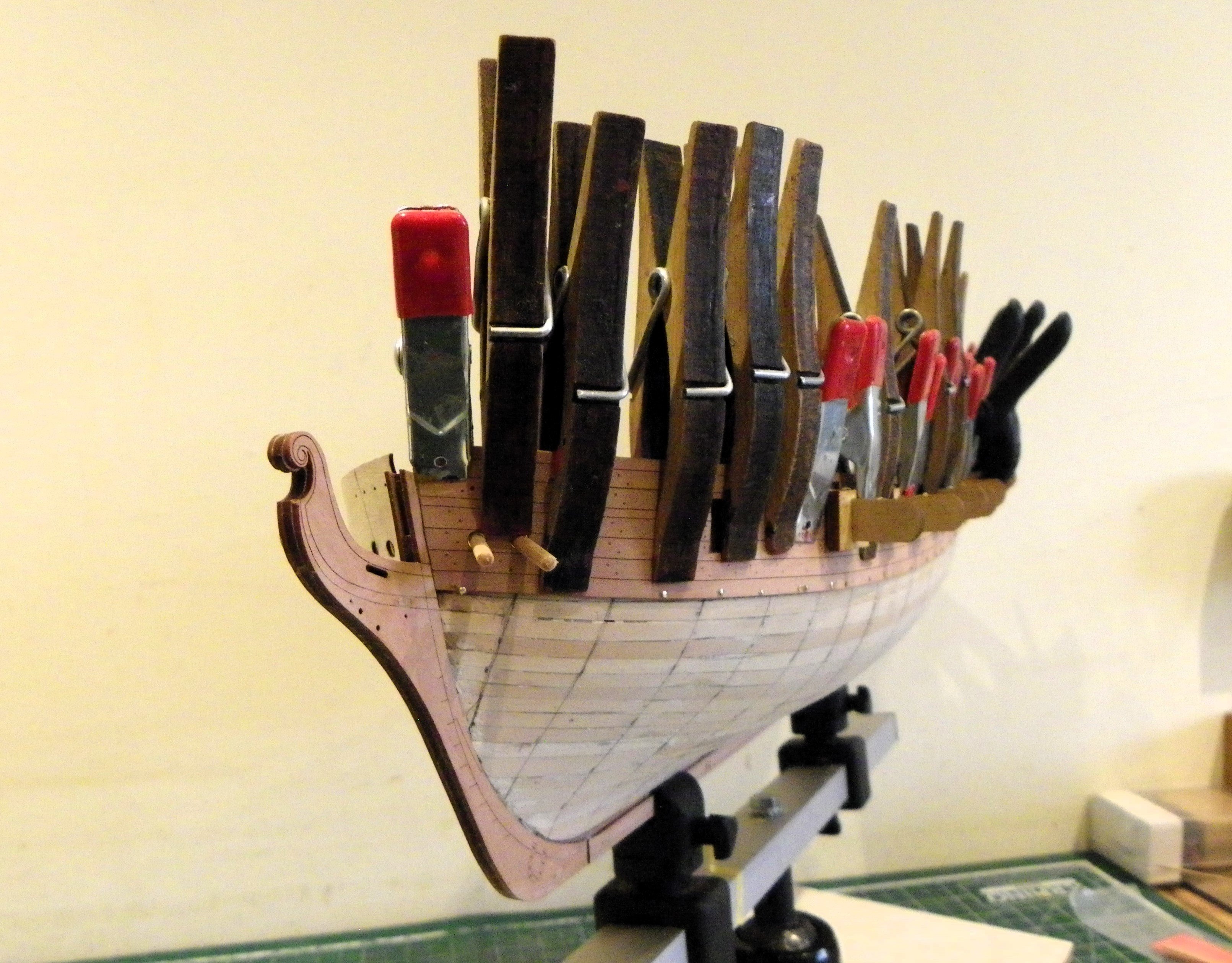
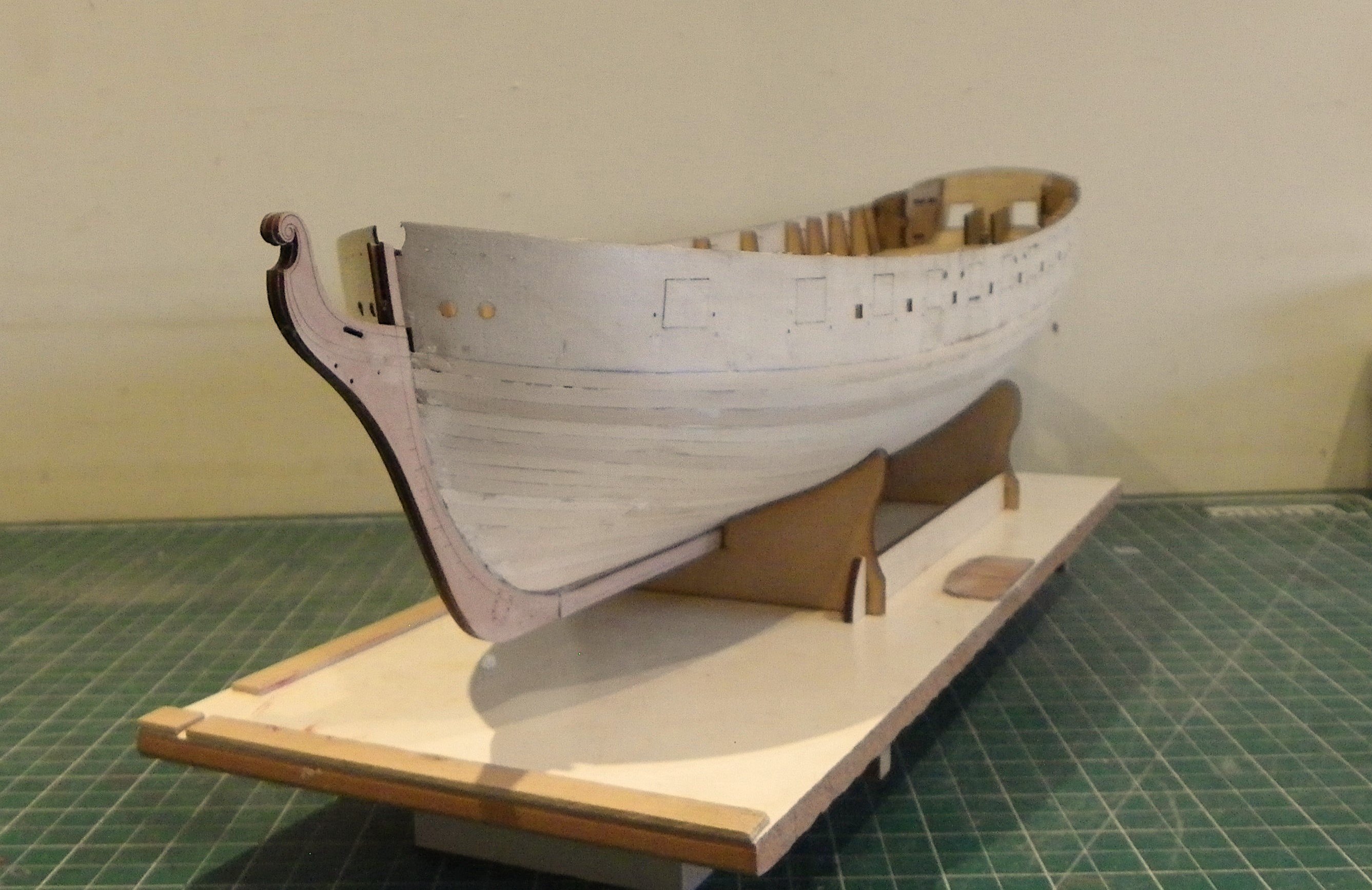
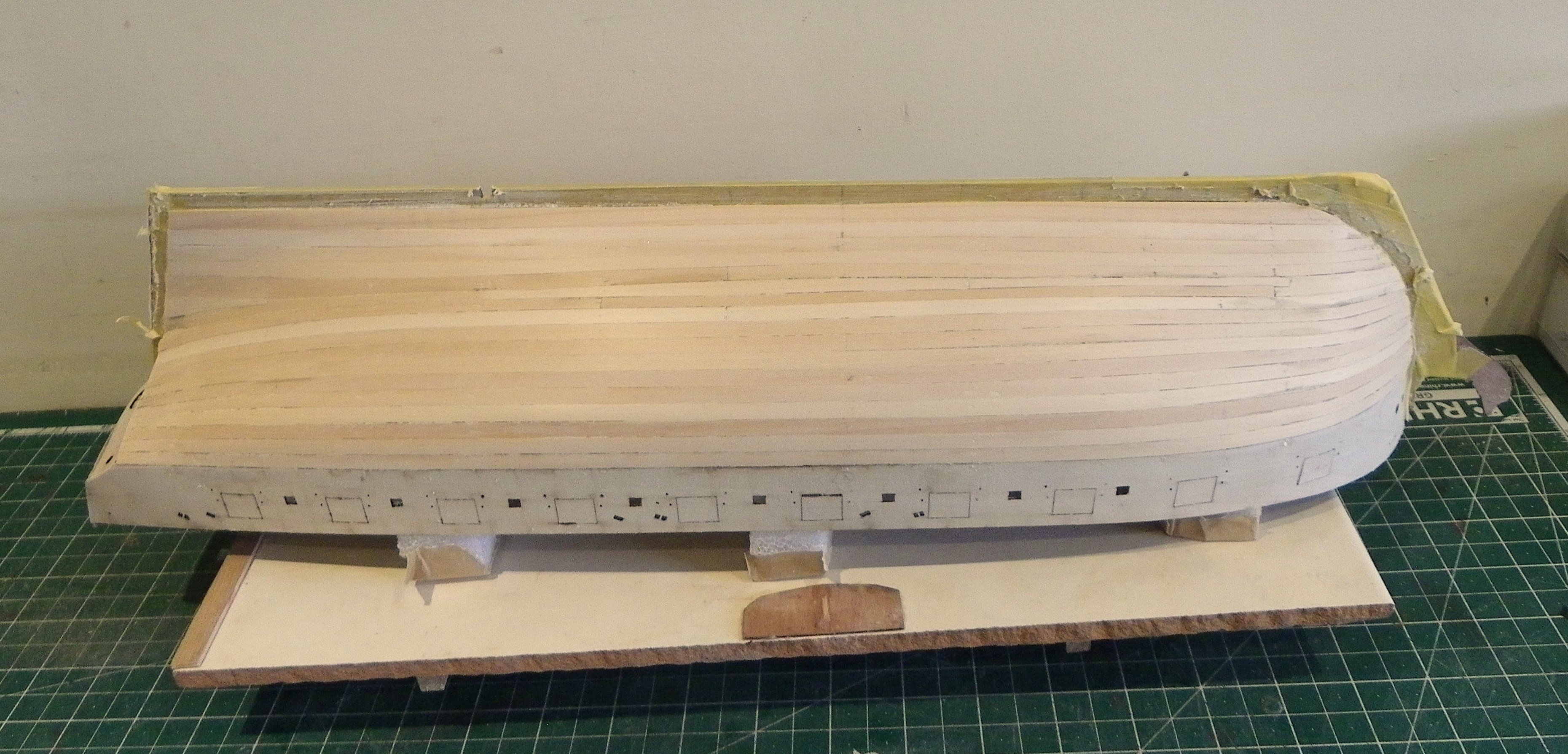
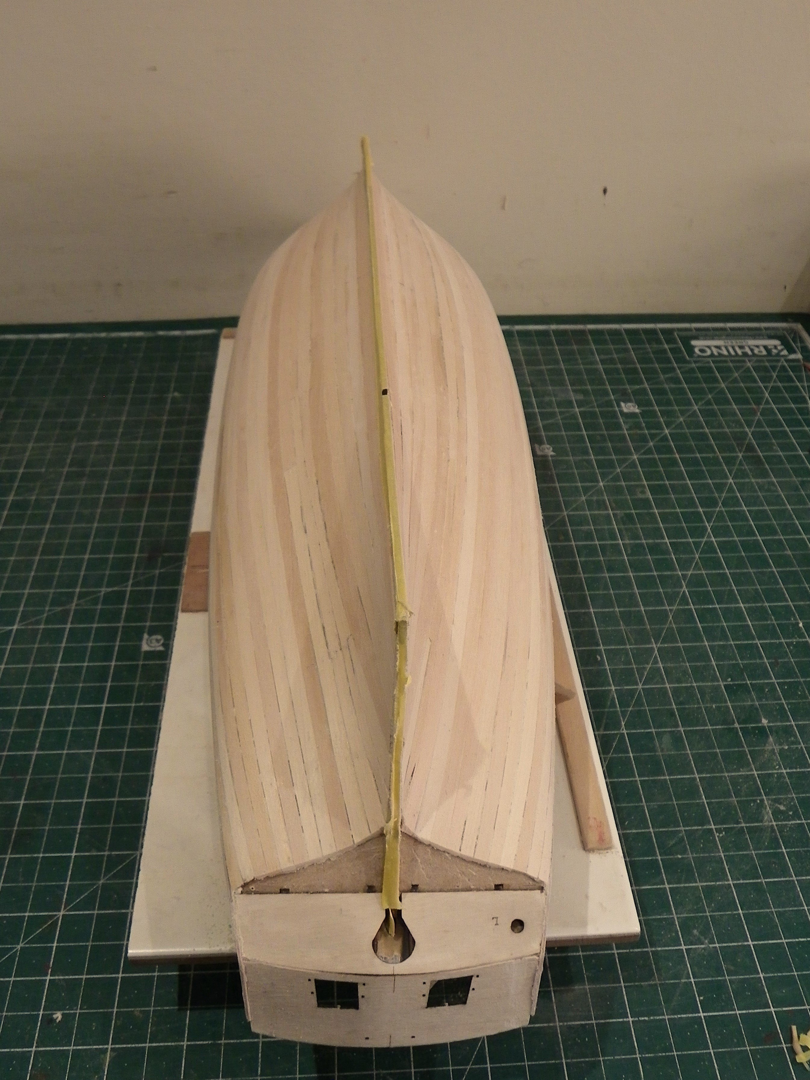
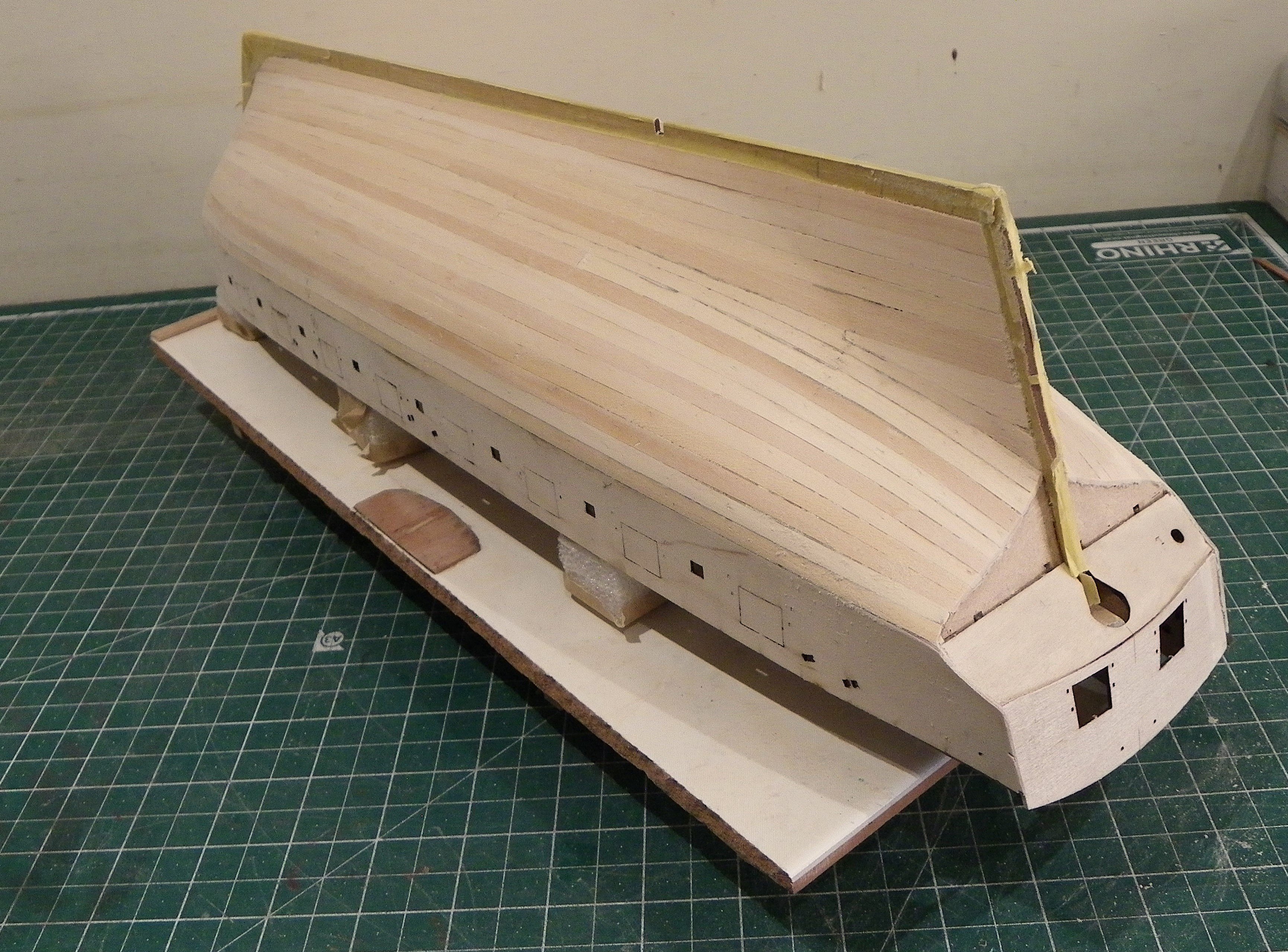
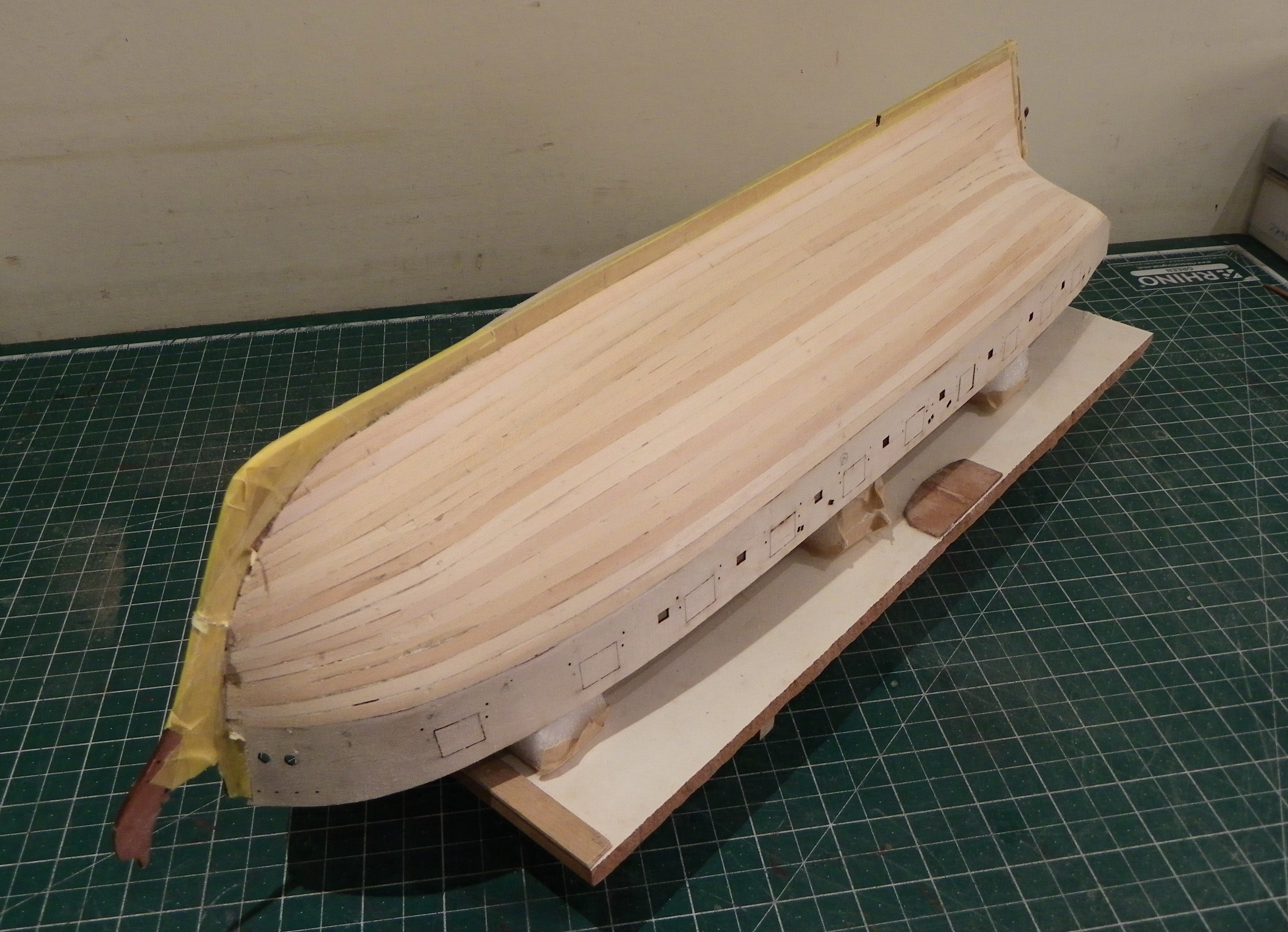
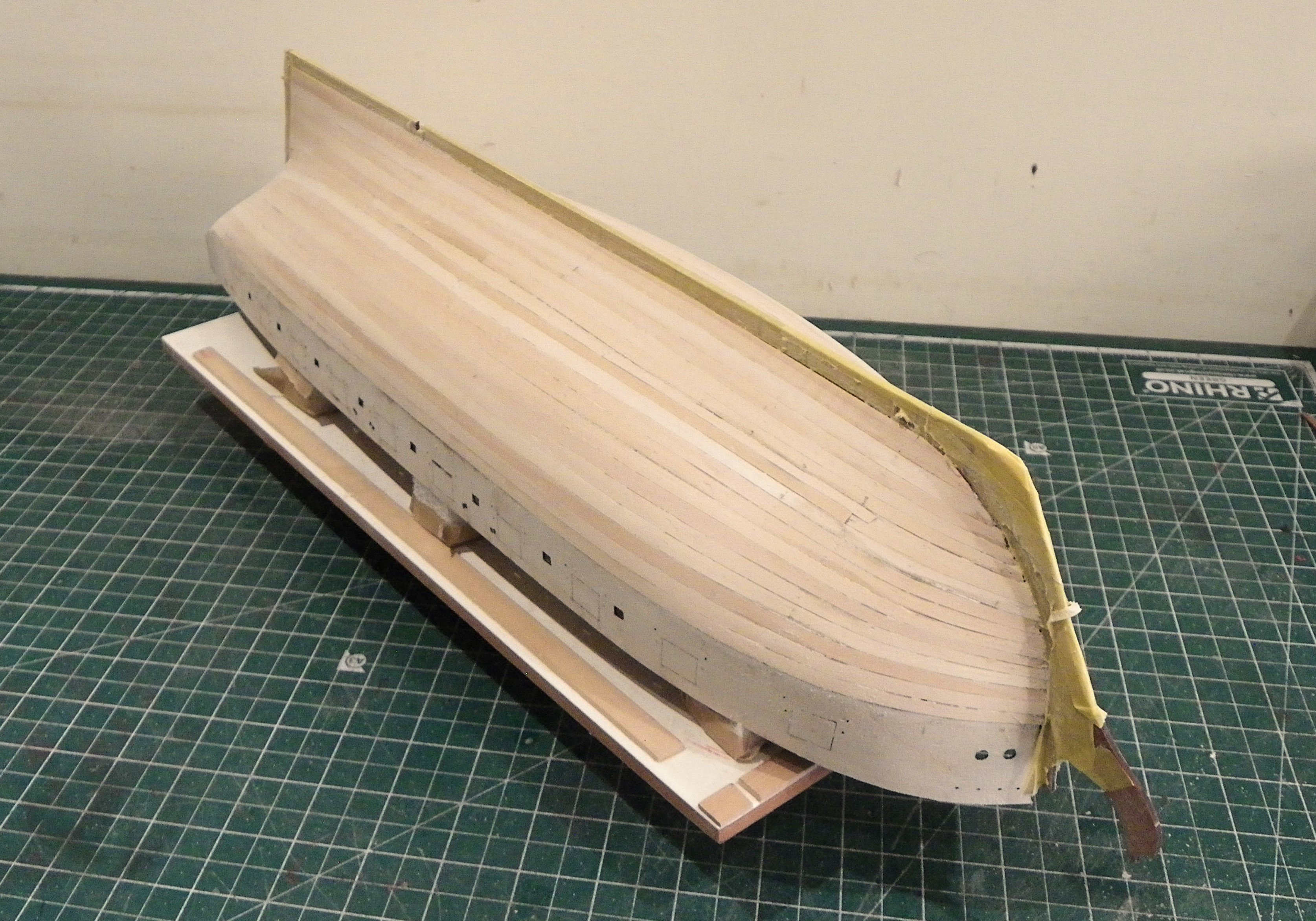
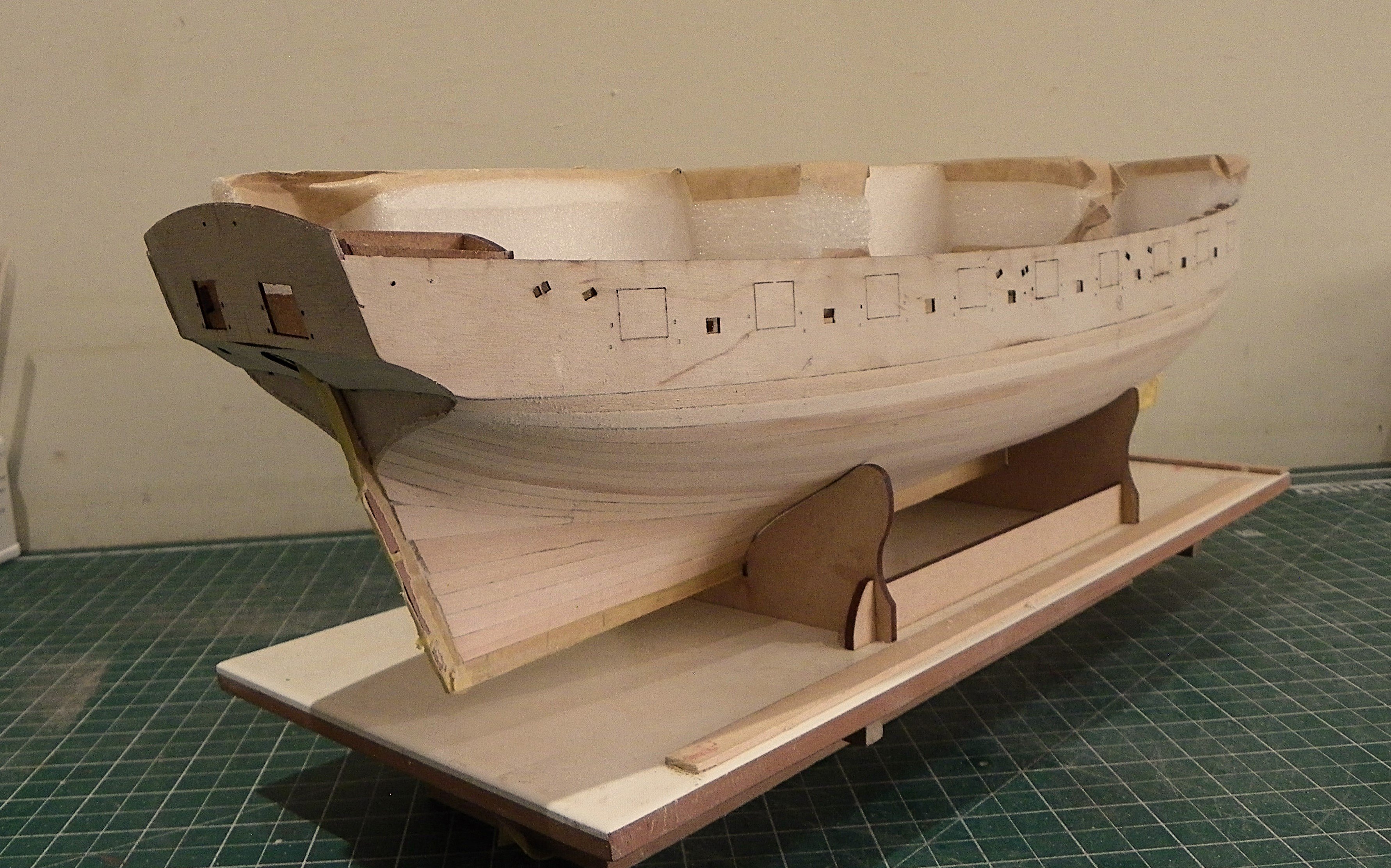
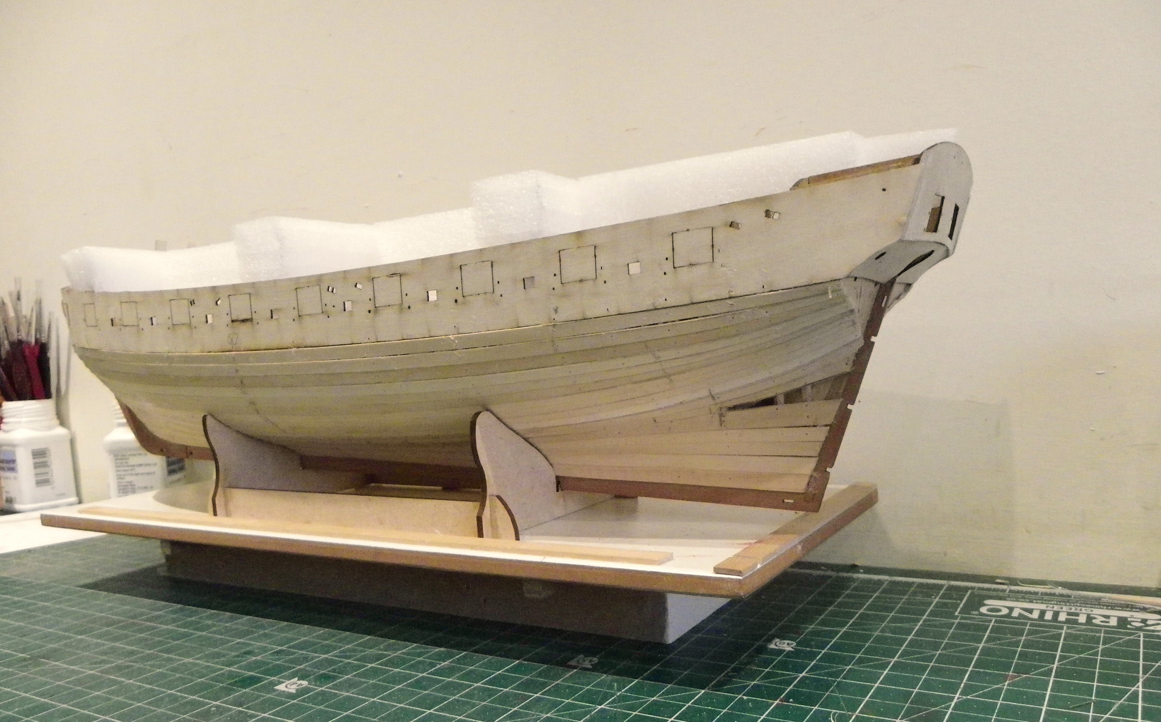
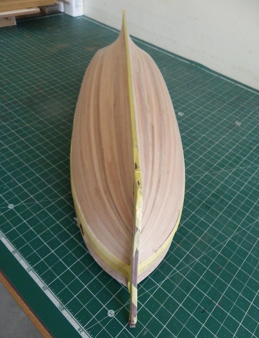
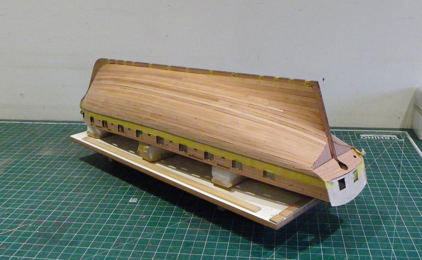
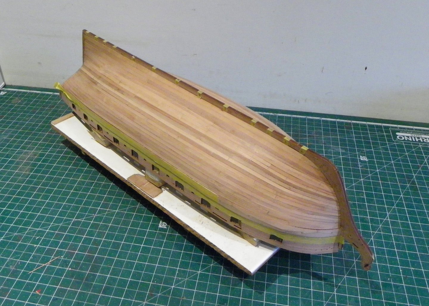
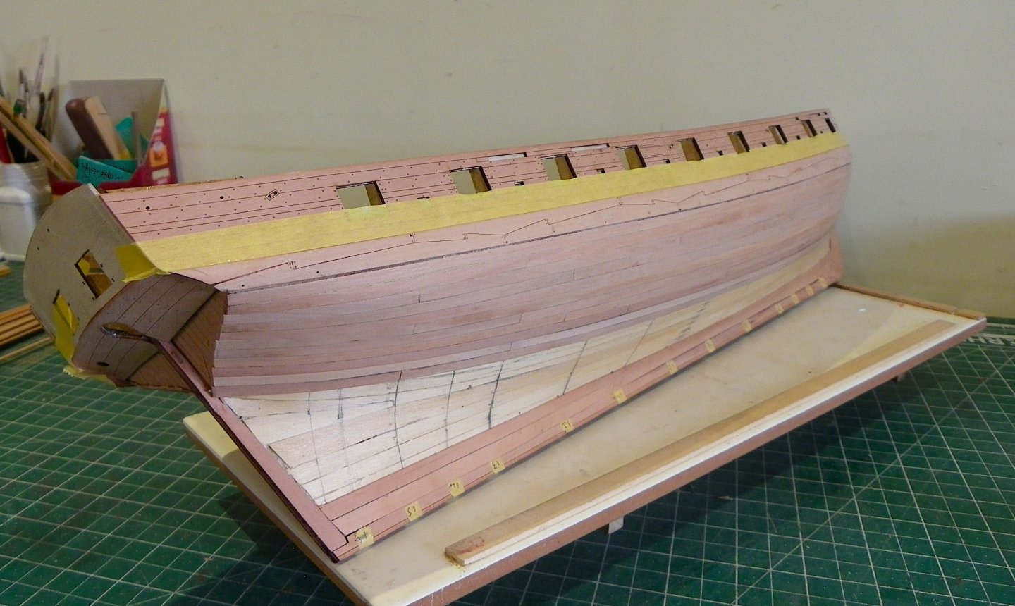
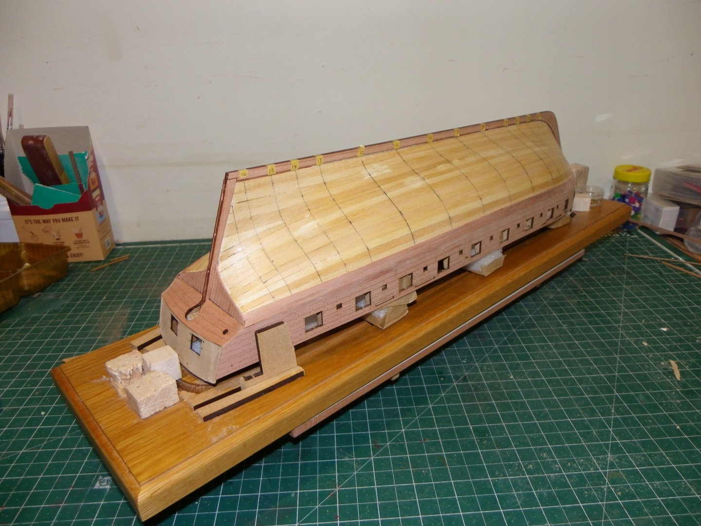
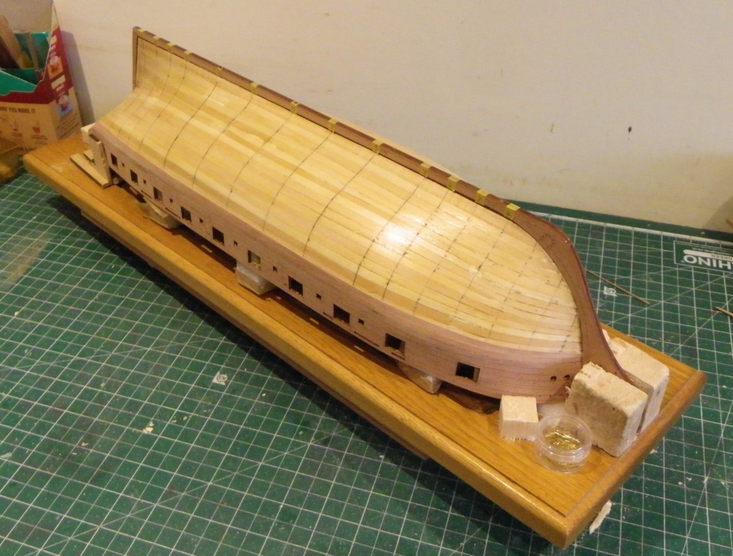
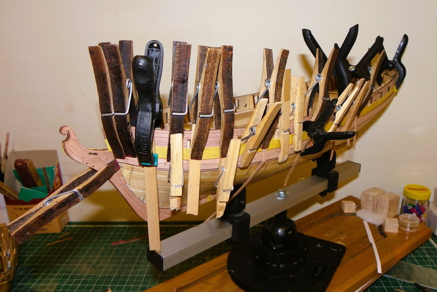
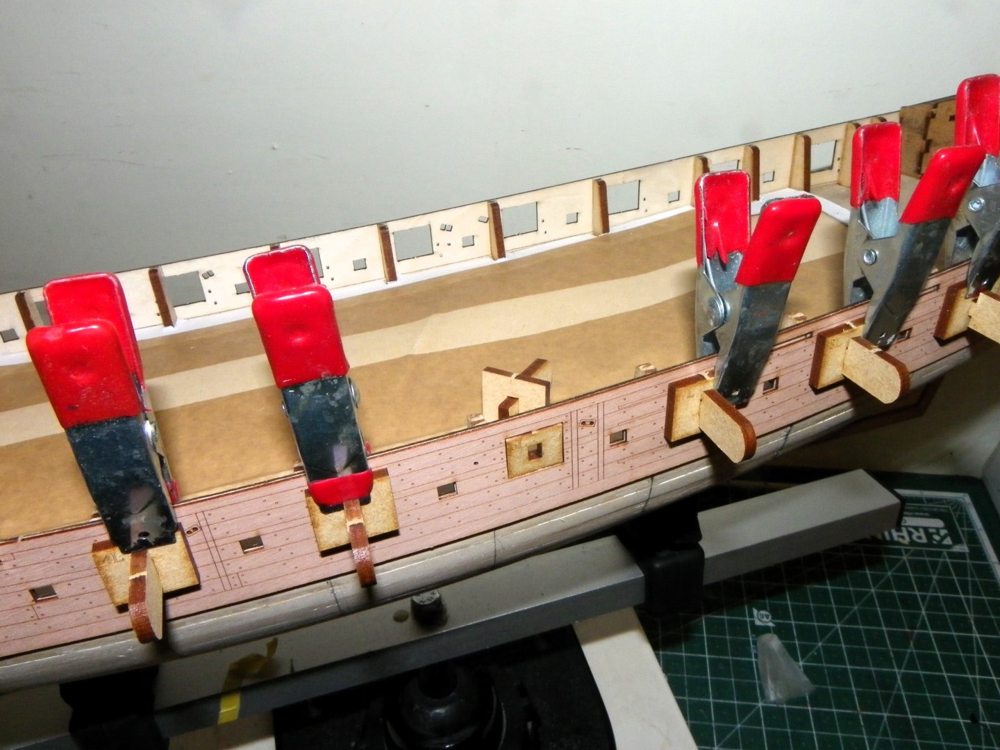
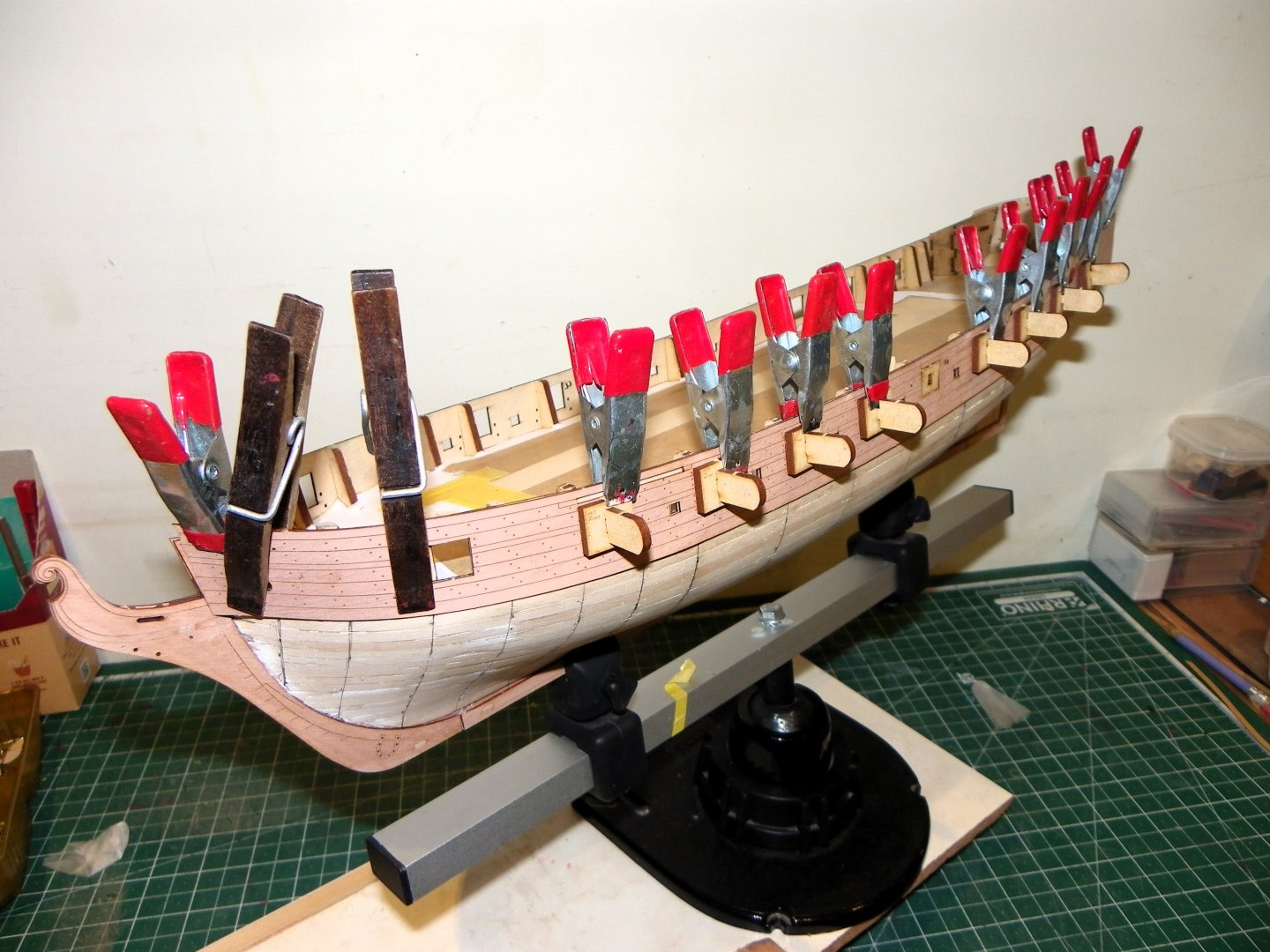
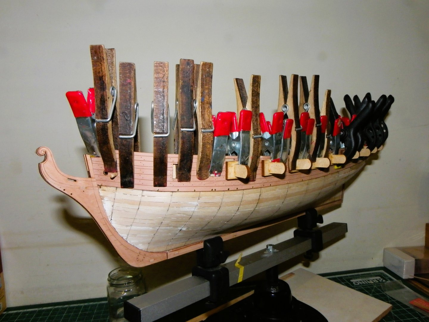
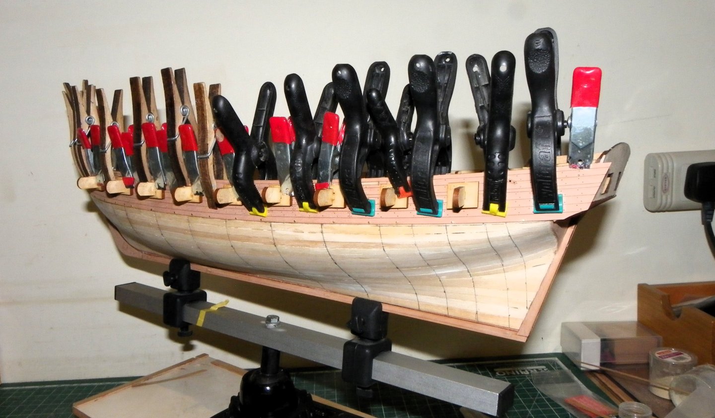
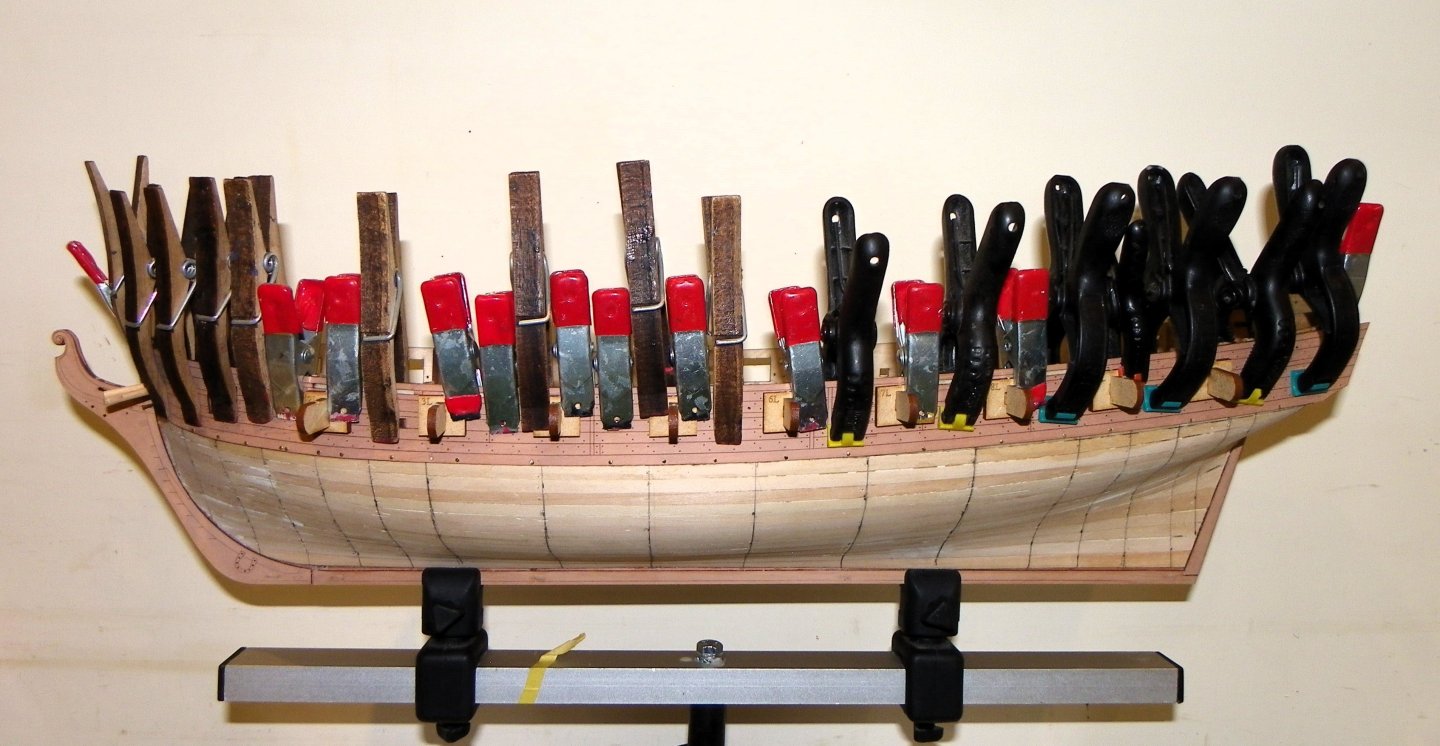
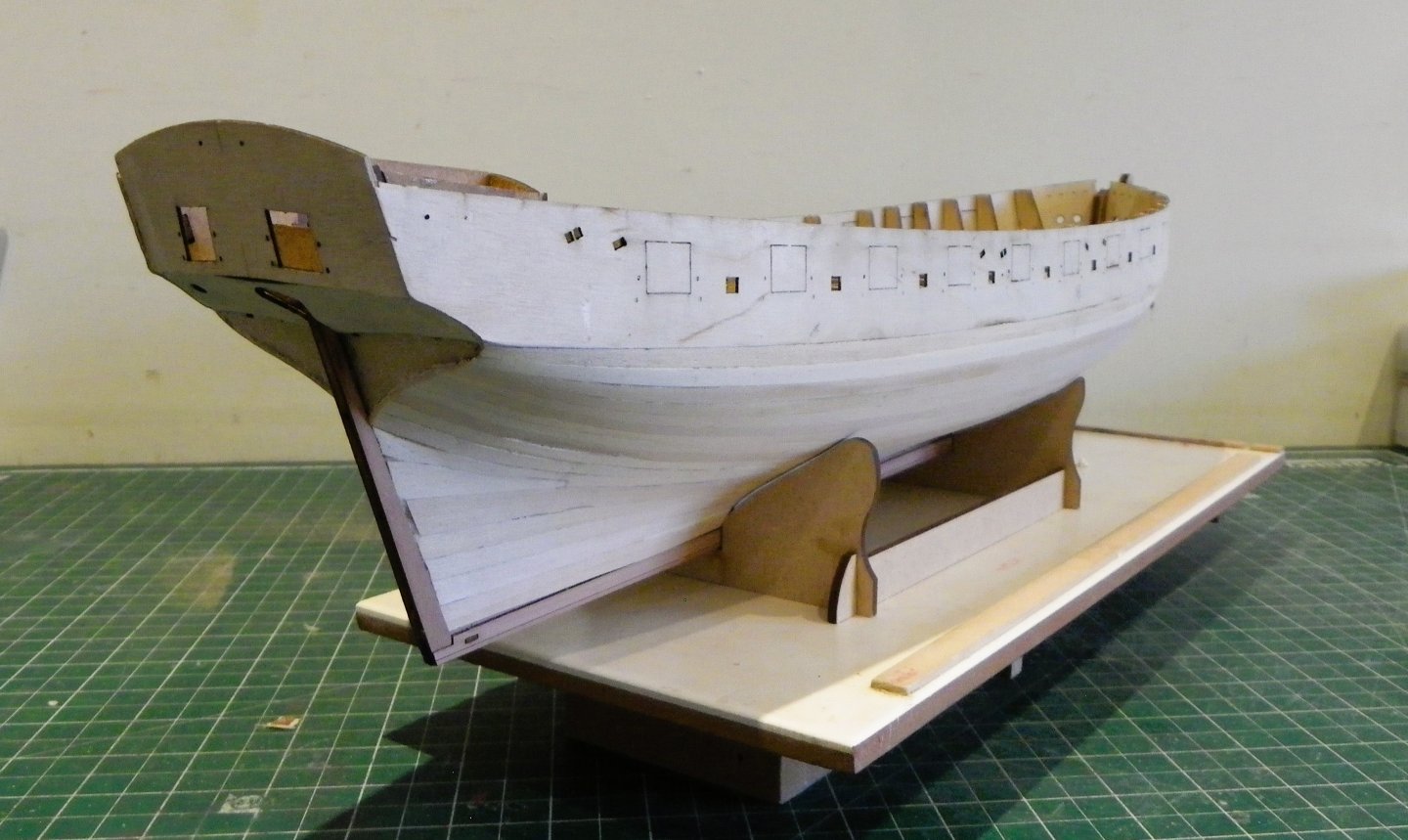
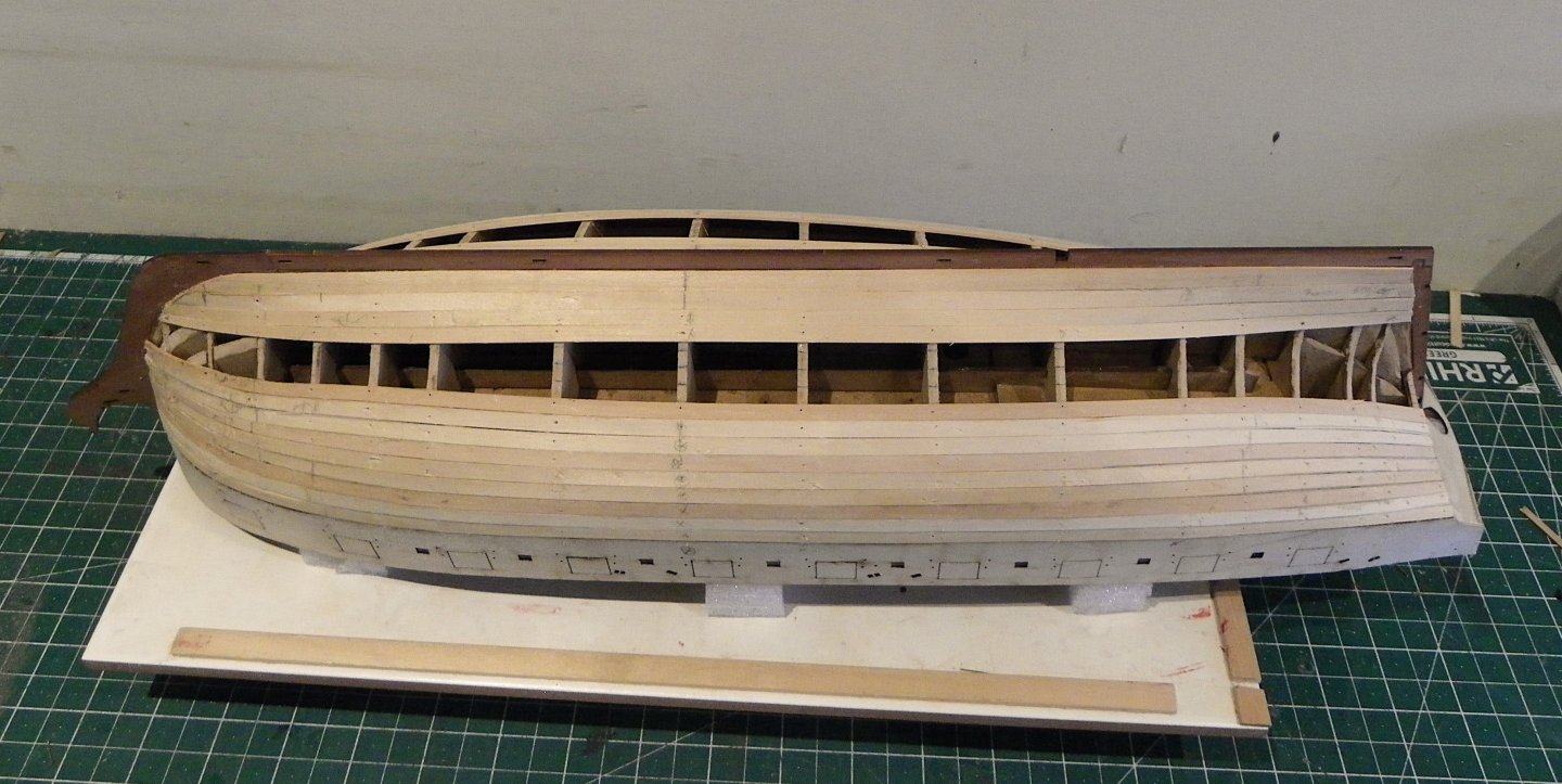
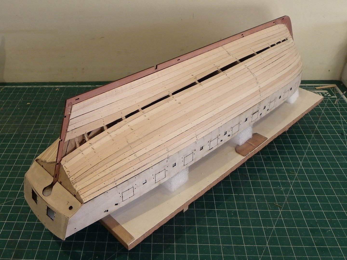
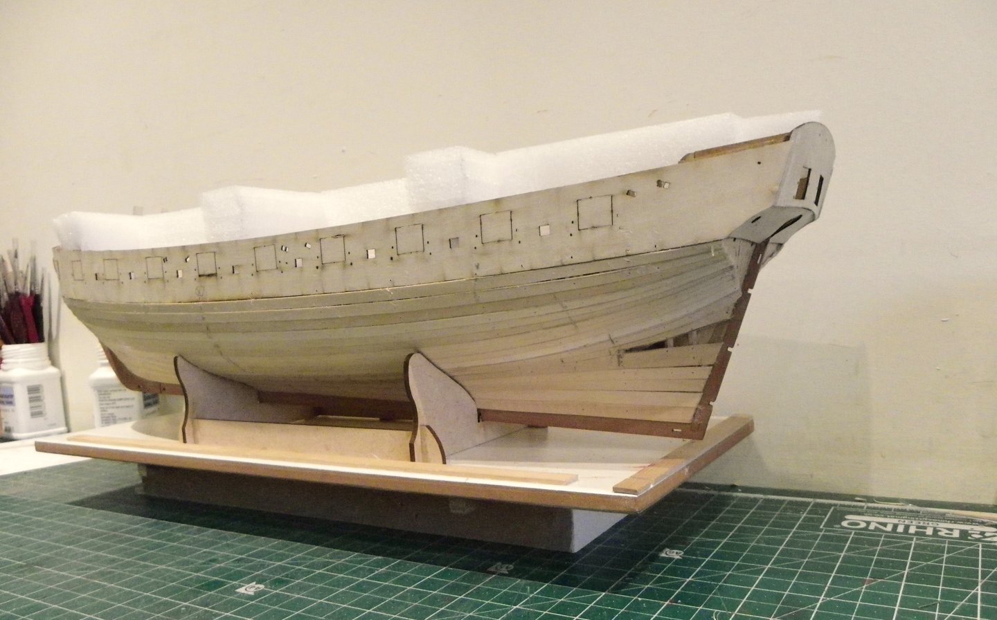
Post 20 Pear wood planking I sorted the planks by colour, keeping even tones for planking below the wales to the waterline. A few were rejected by reason of poor grain match altho’ these could be used for the lower hull particularly if it is to be coppered. I always knock up a temporary support base to hold the hull inverted for planking and coppering. I find it helps a lot to keep the hull steady. 0205 The hull will spend a lot of time inverted. In this shot I have applied two strakes below the Gunport pattern, tapering to 3mm at the bow and leaving full width at the stern. 0206 The hull has been coated with sanding sealer which I think gives a better surface for ca to grip. I also dampen the back of the planks before applying ca, again I think it helps rapid grab. I have taken a different approach to the planking on this model. In reality, and on PoF model building, wales are fitted directly to the frames. I thought I would have a play around and plank down to just below the lower edge of the wale, fit the wales and trim back to the lower edge. The top line of the wale is marked on the Topsides veneer already fitted. 0214 Part of the Pear planking can be seen below the wale, this will be removed. This will allow the planking proper to begin below the wale and run naturally rather than the wale covering the plank below in a random manner. It also allows for the fitting of a drop plank should the mood take me as I know exactly where the wale line is. I initially soaked and pinned the wales to retain the Bow form. At the stern the wale should run under the round of the hull a little, this area was also soaked and pinned. 0211 Getting the wales to fit close is a clamp heavy exercise, and I modify cheap clothes pegs to suit. I used pva to glue the wales. With the wales firmly fixed the planks protruding below are removed, a fairly easy exercise but care had to be taken not to run off line when scoring the plank line for removal. This could prove unfortunate for the wale patterns. I used a new Number11 scalpel blade for the purpose on each side. 002 006 The white area is where planking was removed. This will be lightly sanded and sealer applied. 0016 0018 0022 0026 I can now work out my planking approach. B.E. 17/01/2025


- 332 replies
-
- 32
-
-
- Harpy
- Vanguard Models
- (and 1 more)
-
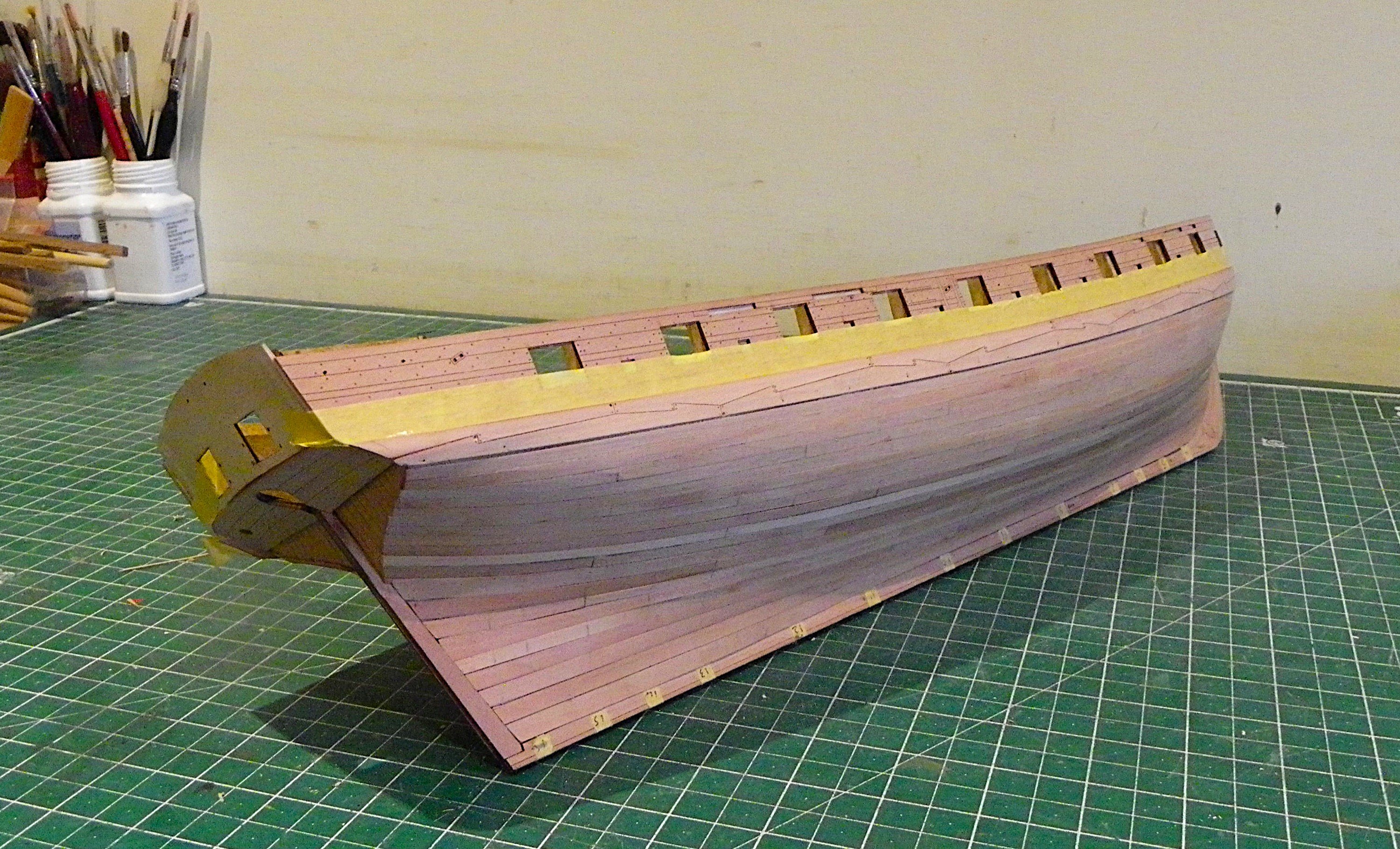
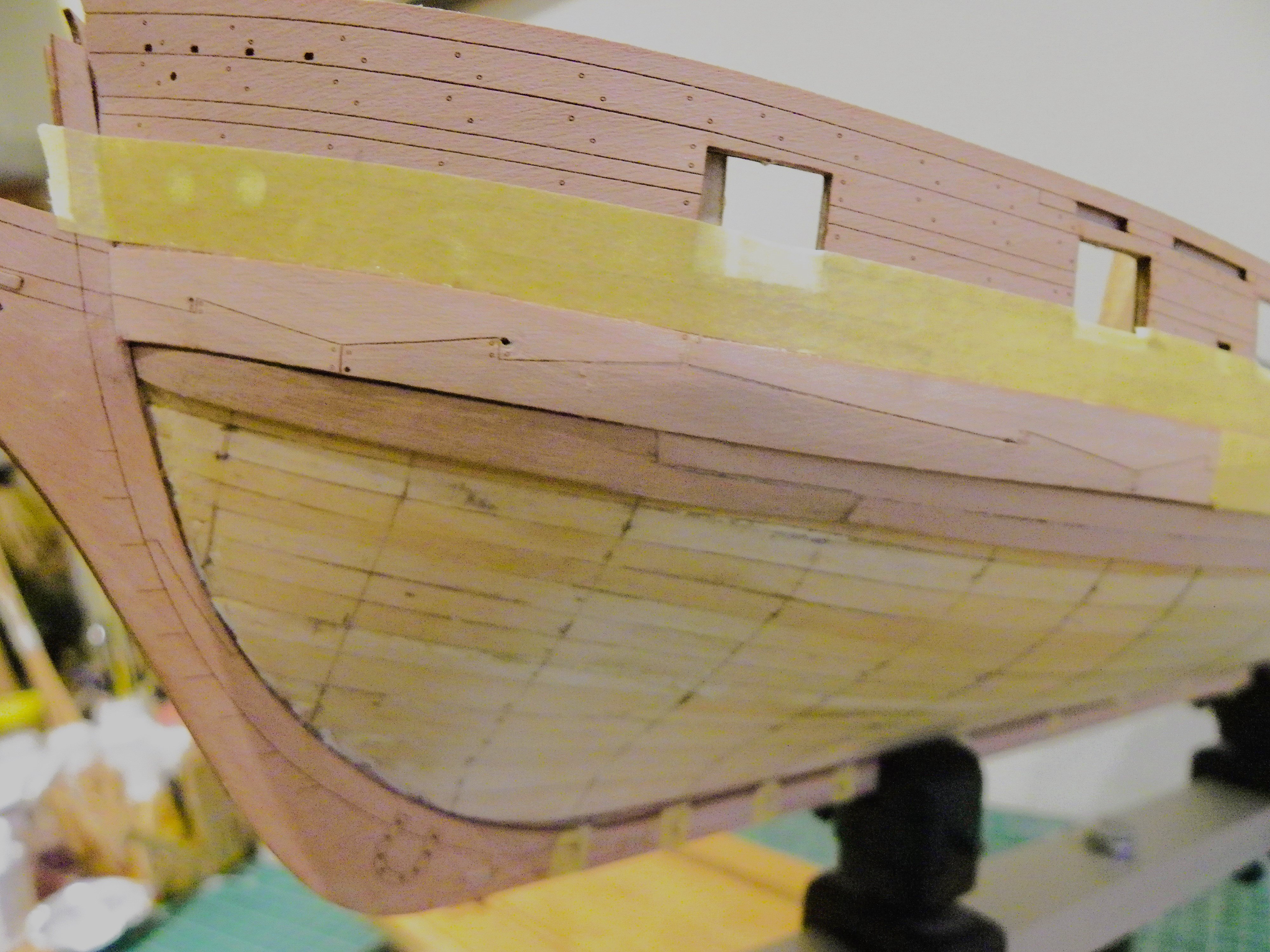
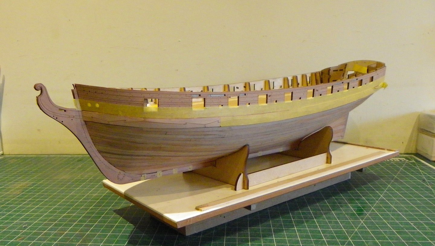
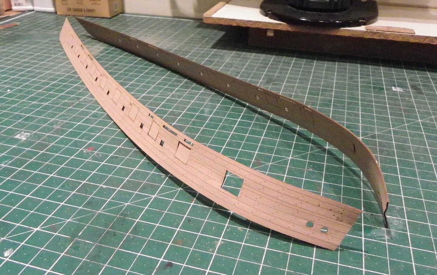
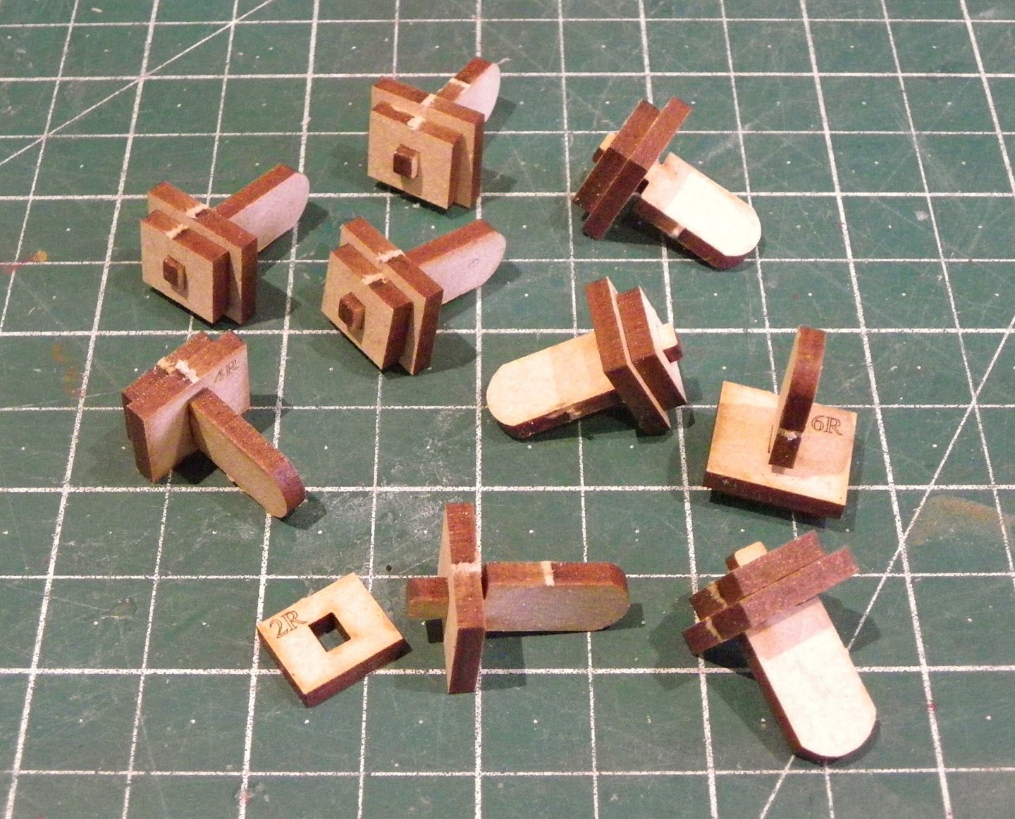
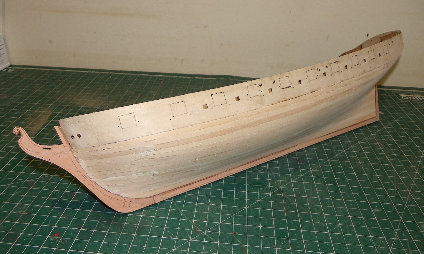
Thank you Chris and Nipper it's satisfying to know that my Logs are of use to others. I too am grateful for the logs of others who also help me along the way. Post 19 Topsides The beautifully detailed Topsides save a lot of effort in planking around the gunports and what look like sweep ports. 0165 0170 Before I started, I marked the station lines down the hull to assist the planking. 0171 0174 The pattern was soaked at the forward end and clamped to the hull overnight to take the stress out of the bow curve. A useful innovation designed by Chris are gunport alignment jigs. These are handed Port and Starboard and fit the ports from 2 at the Bow to 10 at the stern. 0177 0178 Before I applied glue anywhere near the patterns I dry fitted with the jigs in place. The jigs need a little cleaning-up by removal of any fret nubs to ensure a perfect fit. Once gluing is in progress you don’t want to be fiddling around trying to get the jigs into place. 0182 Once I was happy with the fit of the jigs I glued the two sections together. I did find that I needed to finely shave the bow end of the pattern by degrees to allow alignment with the ports, several dry fit checks were necessary before I committed to glue. This is a critical part of the build and it has to be correct. Gluing is a tricky business given the length of the pattern. 0184 0187 I chose to start at the bow, gluing and clamping along to the third port whilst checking the alignment at the stern. The pva was applied to the hull. I did find it necessary to pin all along the bottom edge of the pattern to counter the tendency to curl. I used slightly thicker pins than those provided for this purpose. 0186 I then progressively glued along the hull at three port intervals, constantly re-checking the fit of the jigs, and removing/ replacing them to avoid any risk of stray glue sticking them. 0191 It has taken the best part of a day to get one side fitted. 0193 A main consideration is to guard against marring the surface of the Pearwood veneers. Unwanted pva or ca will be problematical, and I have both clean water and Acetone handy to immediately clean off any spills. Onto the Starboard side. B.E. 13/01/2025


- 332 replies
-
- 25
-
-
- Harpy
- Vanguard Models
- (and 1 more)
-
Thanks Dave, obviously it would be a faux arrangement as I'm constrained by the kit bulkhead set up, but hopefully it would look a tad more authentic than end grain planks. I wish you good fortune with the carving, keep you chisels sharp and cuts small. I always find the tension rising as I get towards the completion of a piece, particularly if I am pleased with it, there's always that worry..... Cheers, Maurice.
- 332 replies
-
- 3
-
-
- Harpy
- Vanguard Models
- (and 1 more)
-
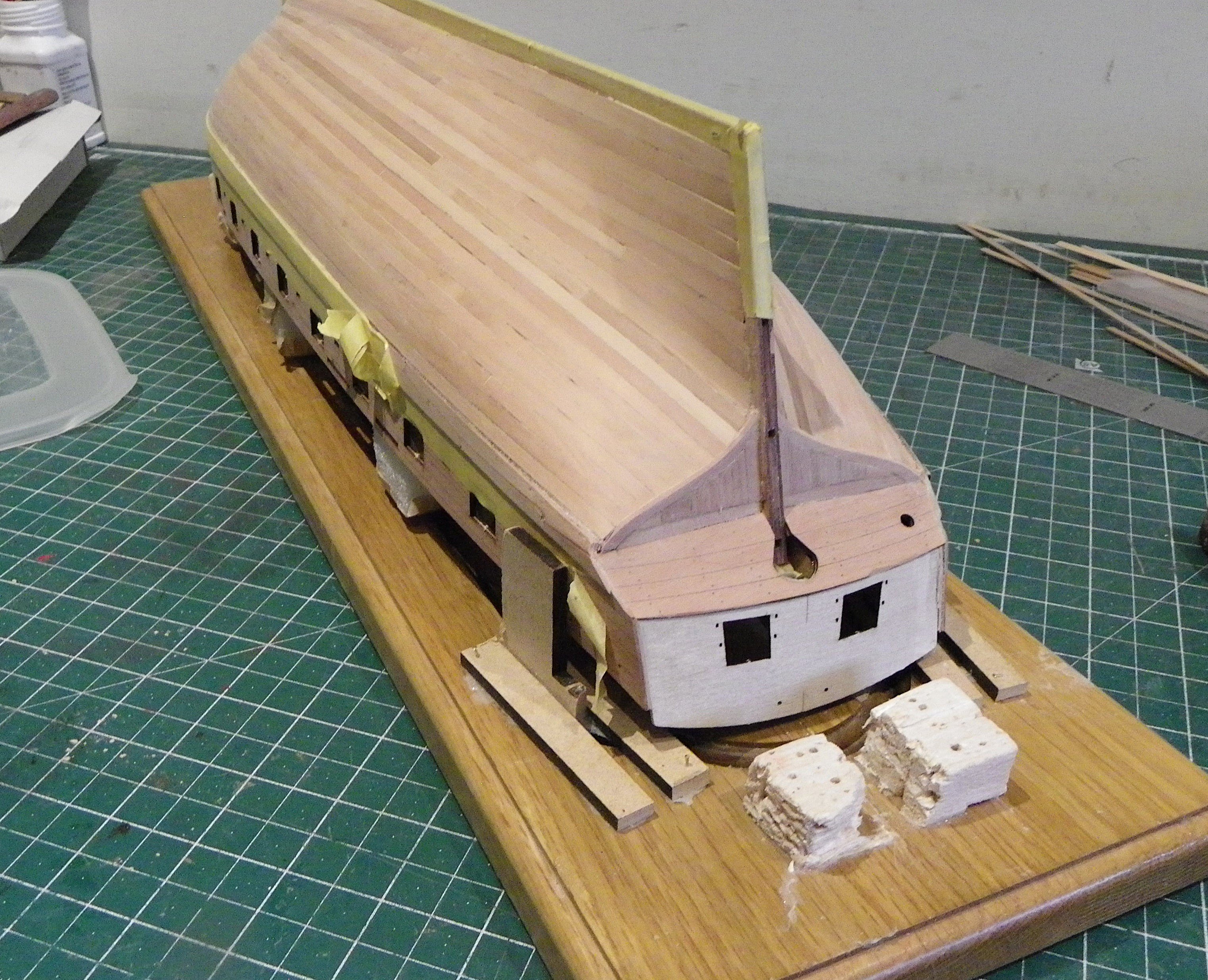
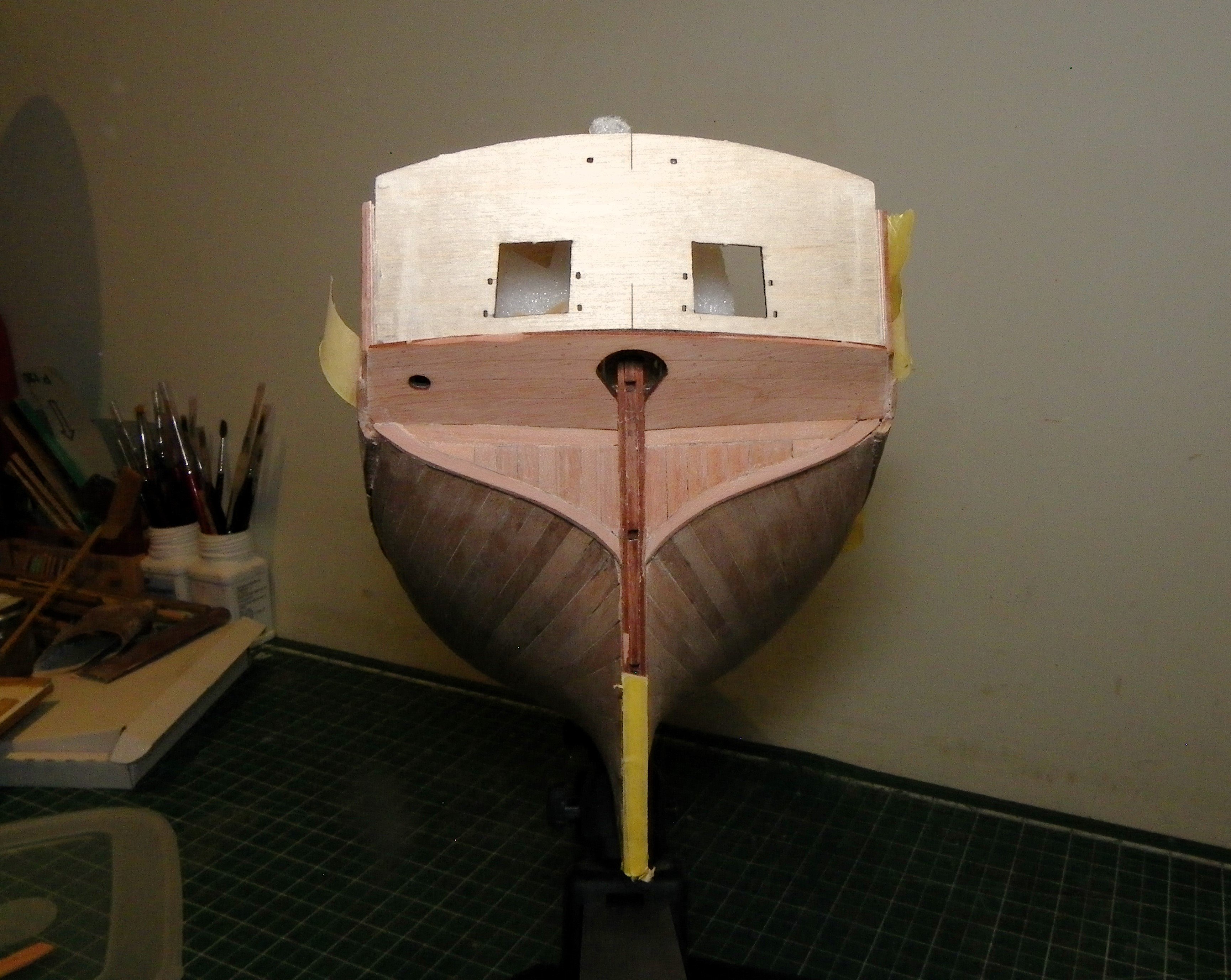
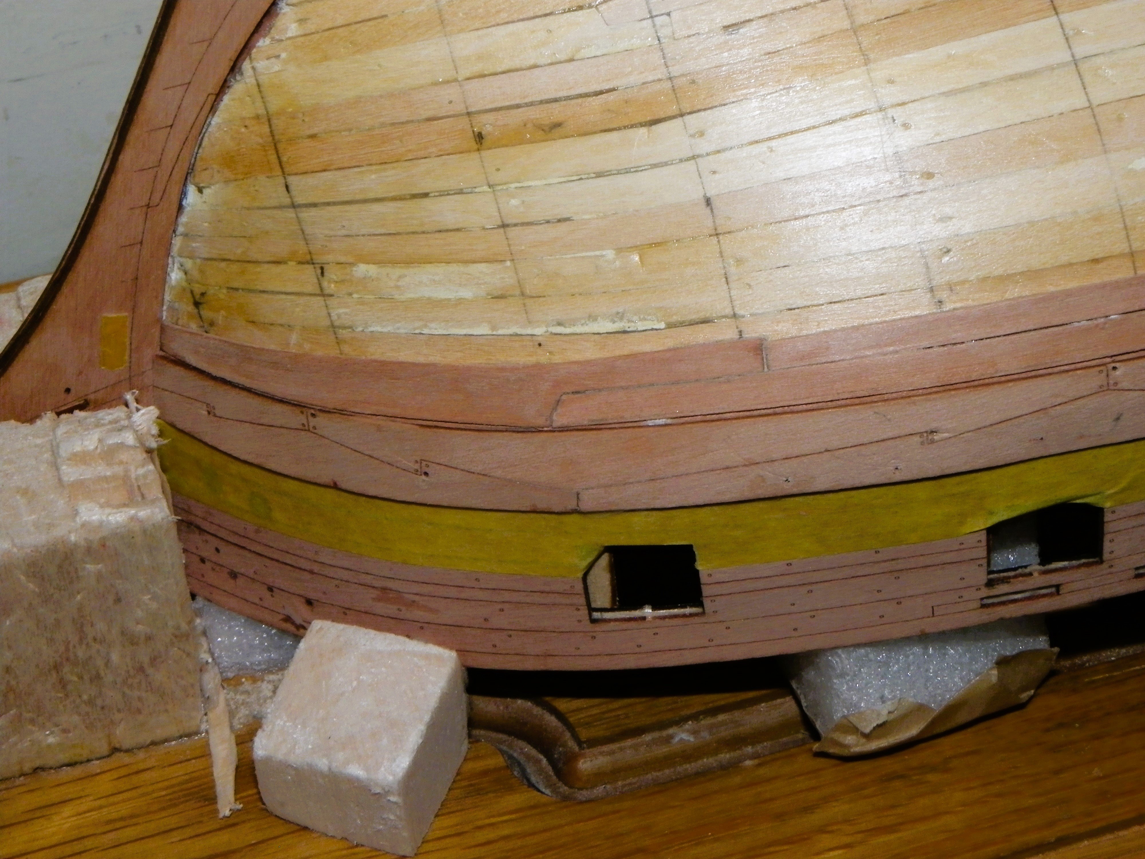
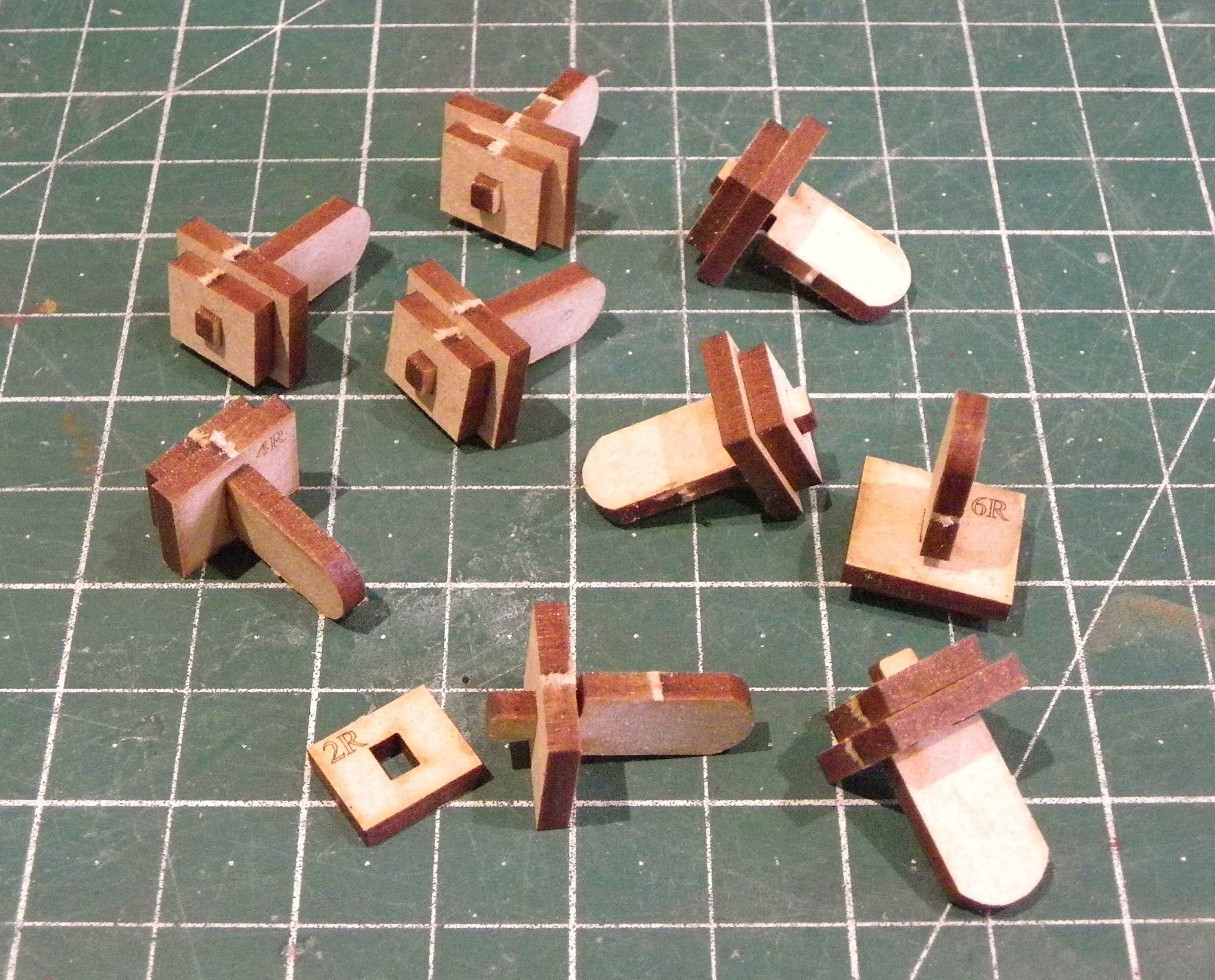
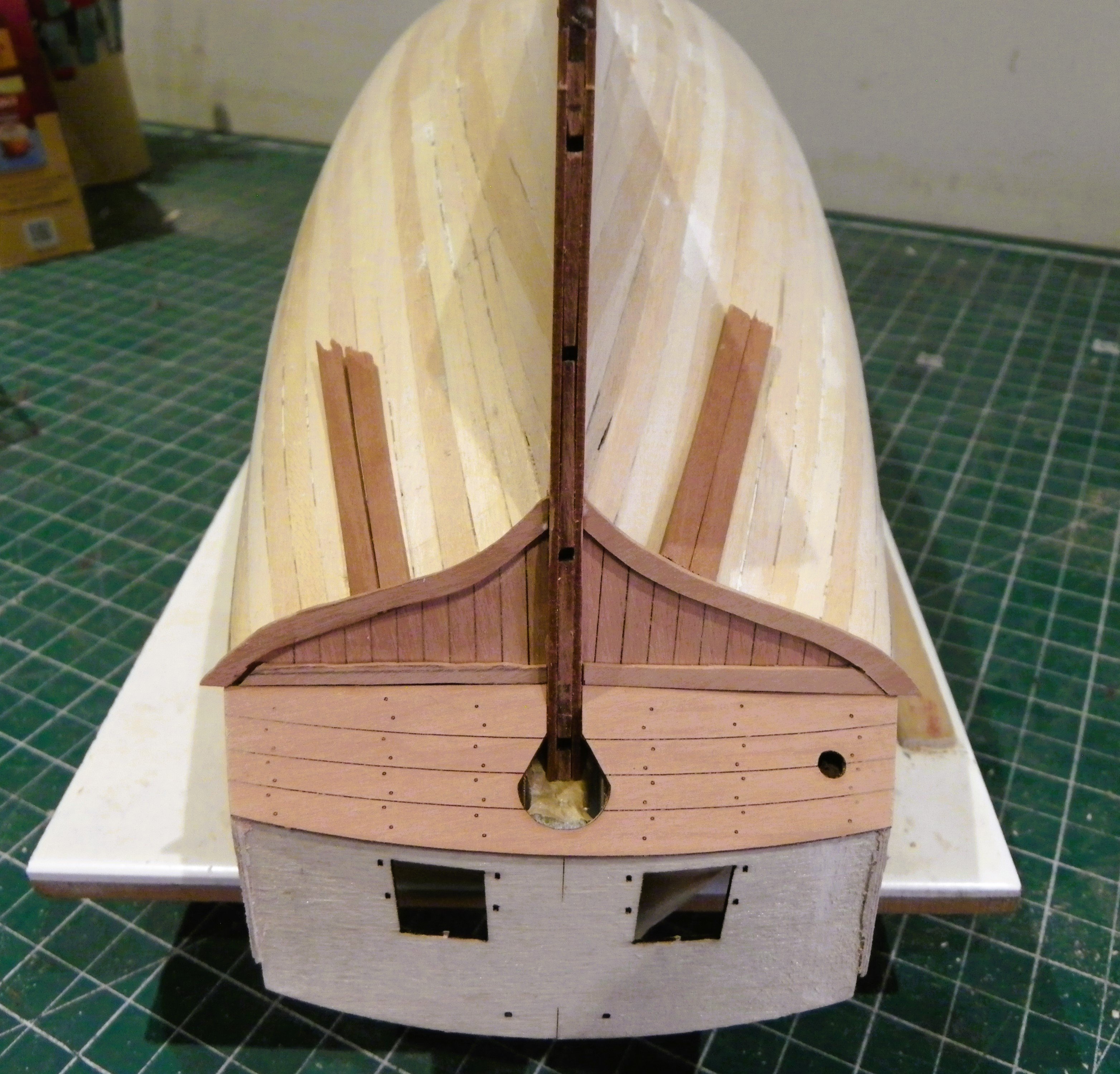
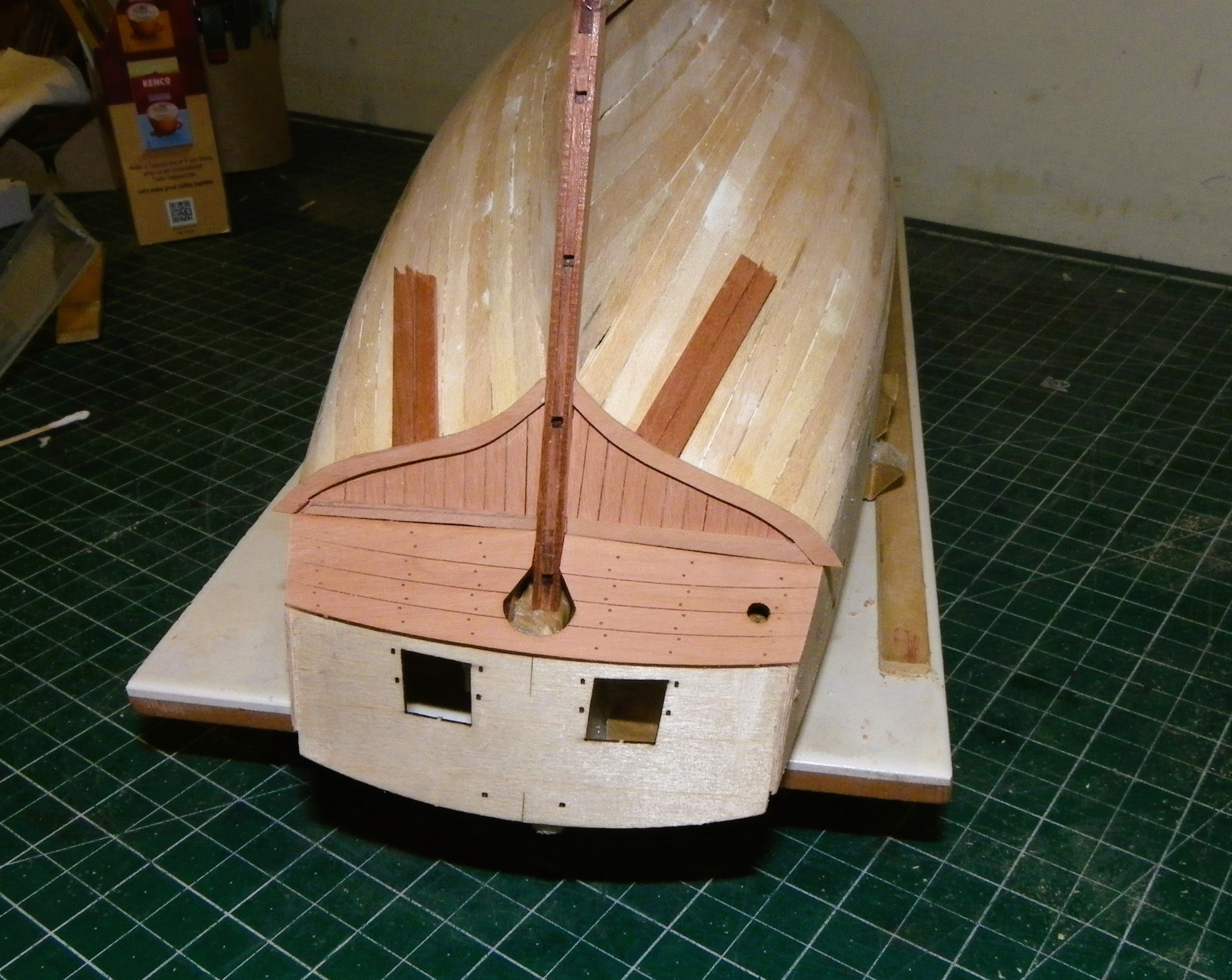
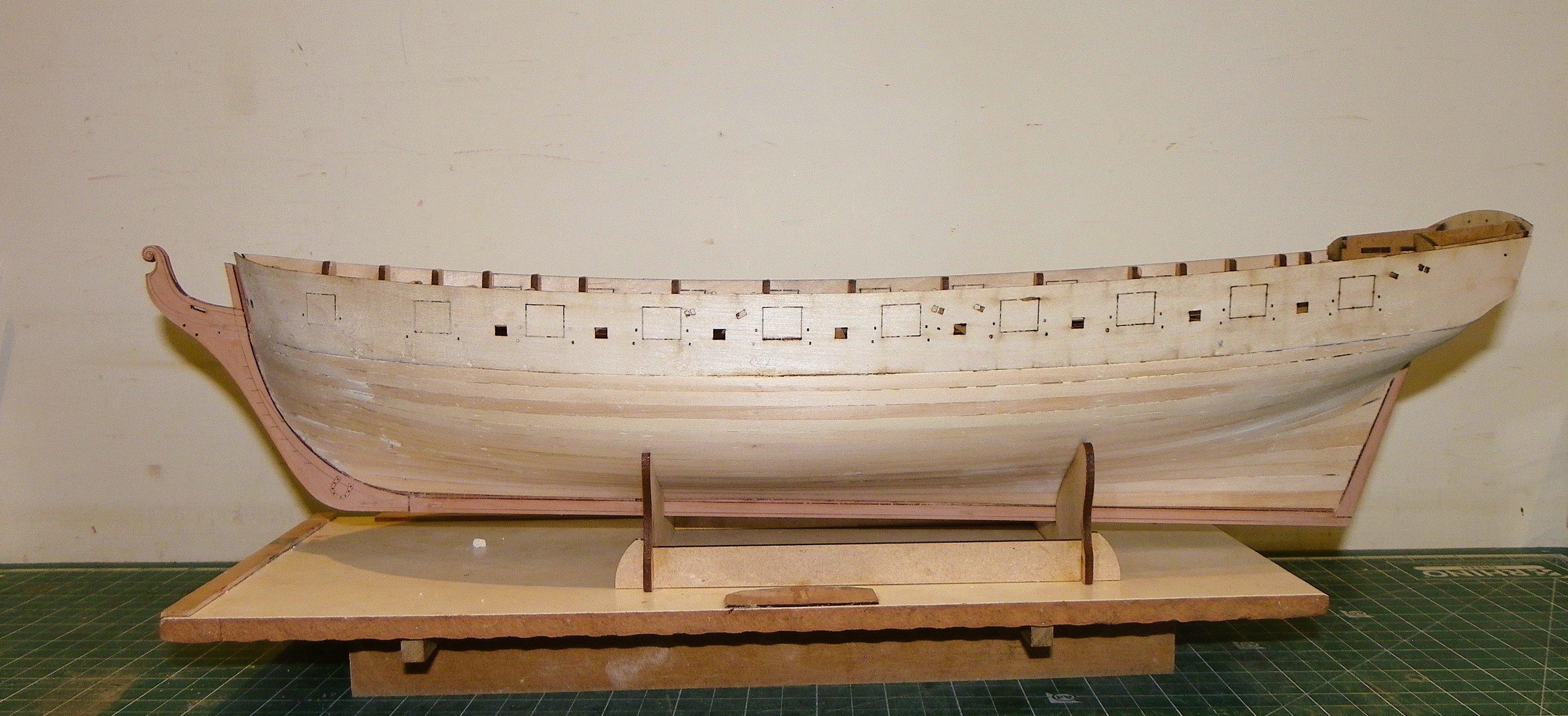
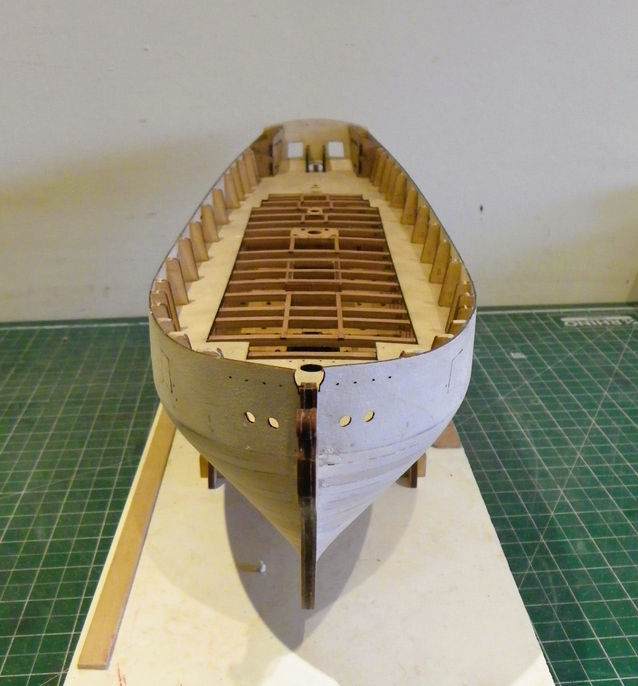
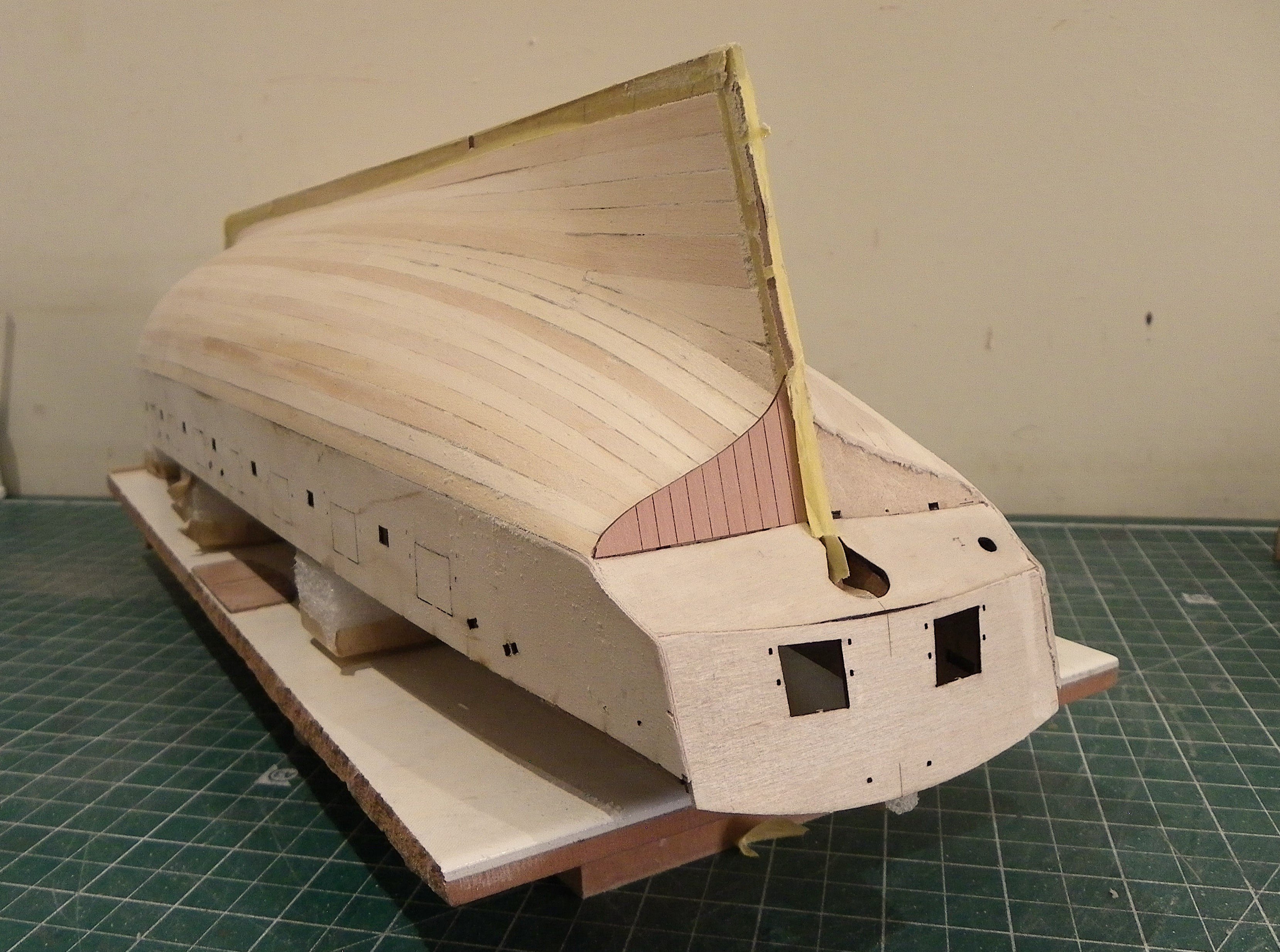
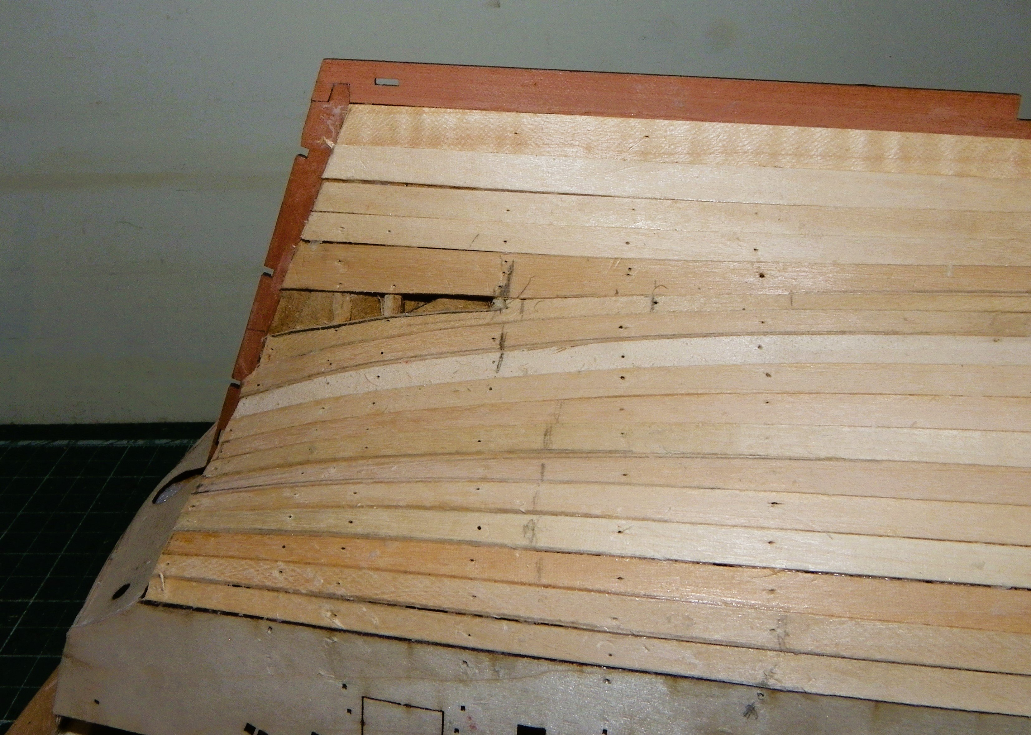
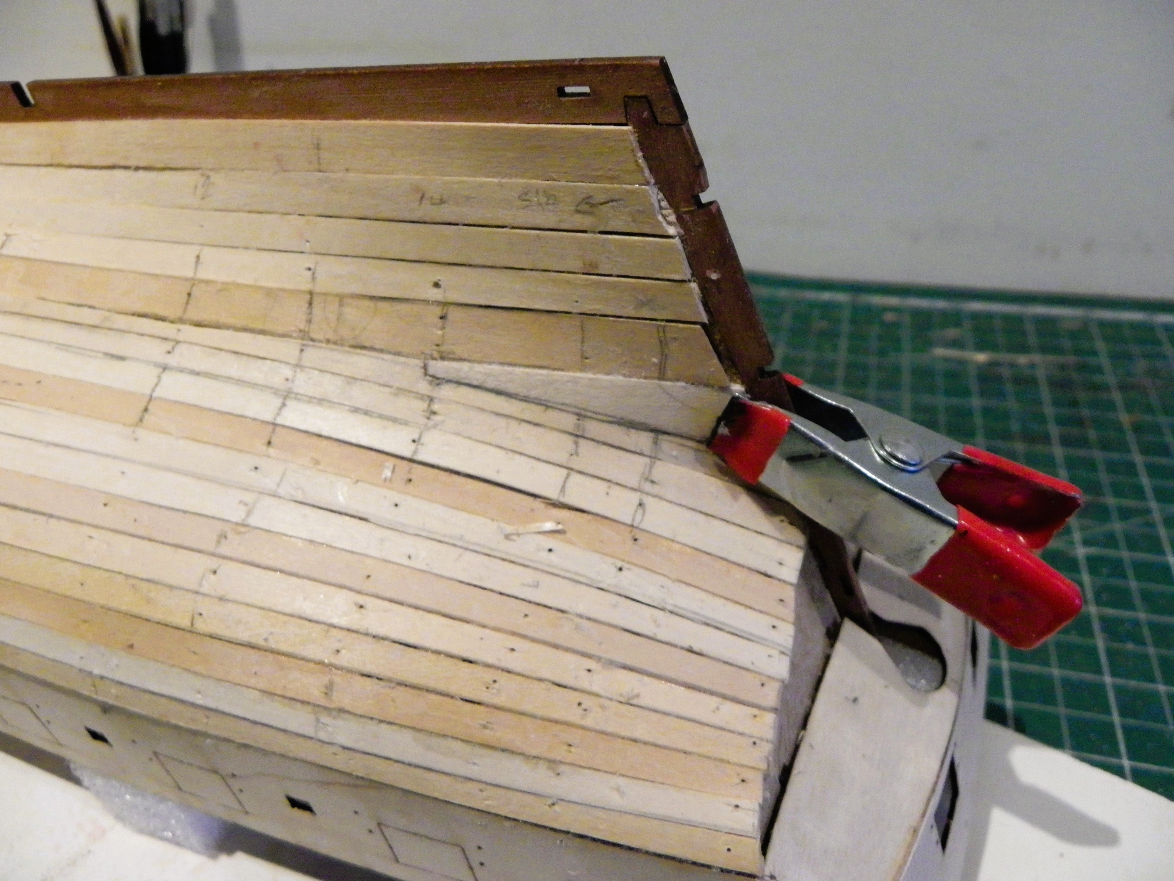
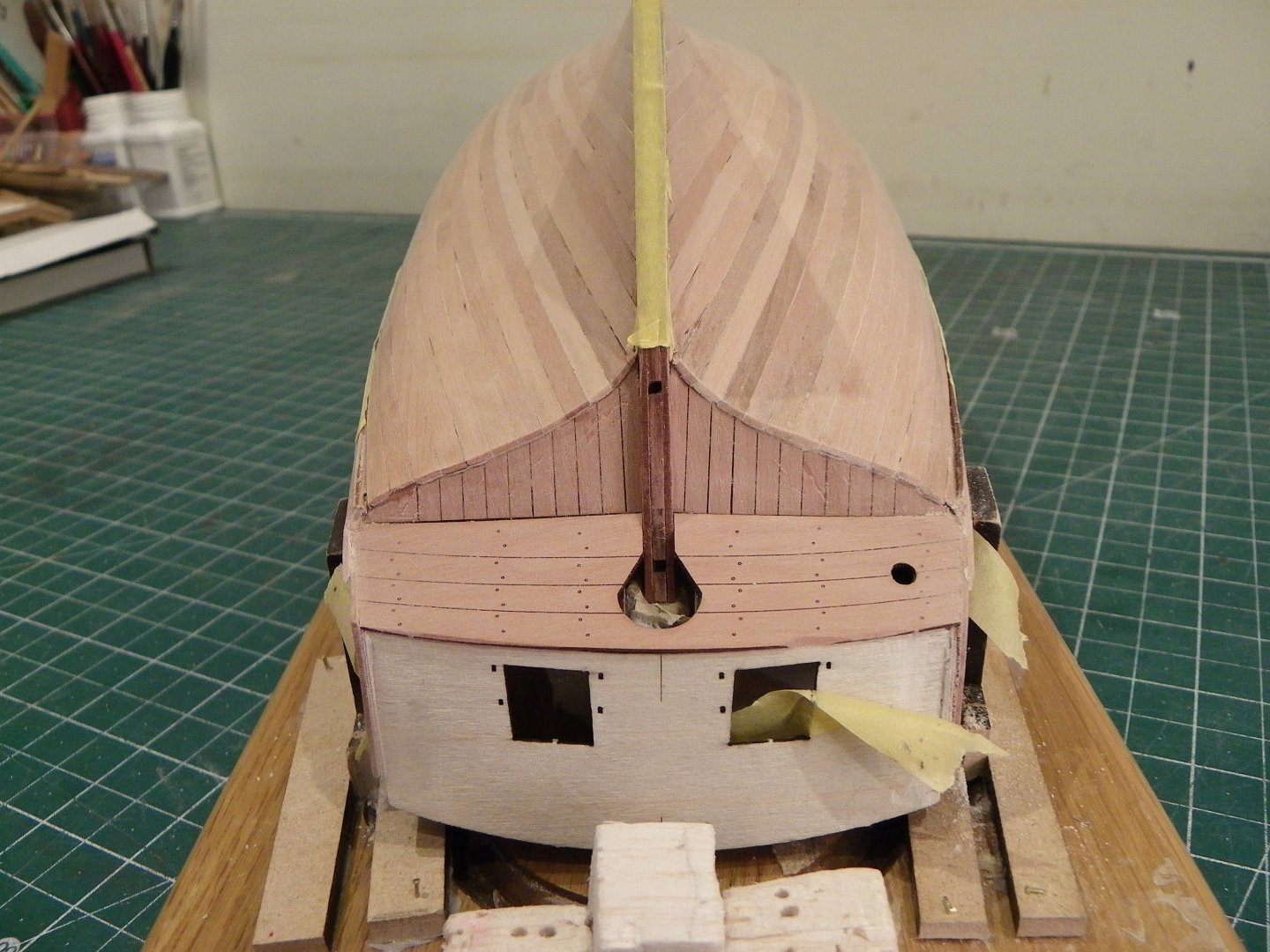
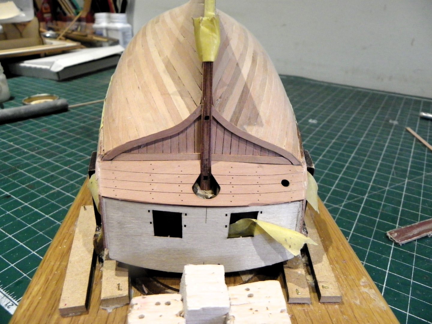
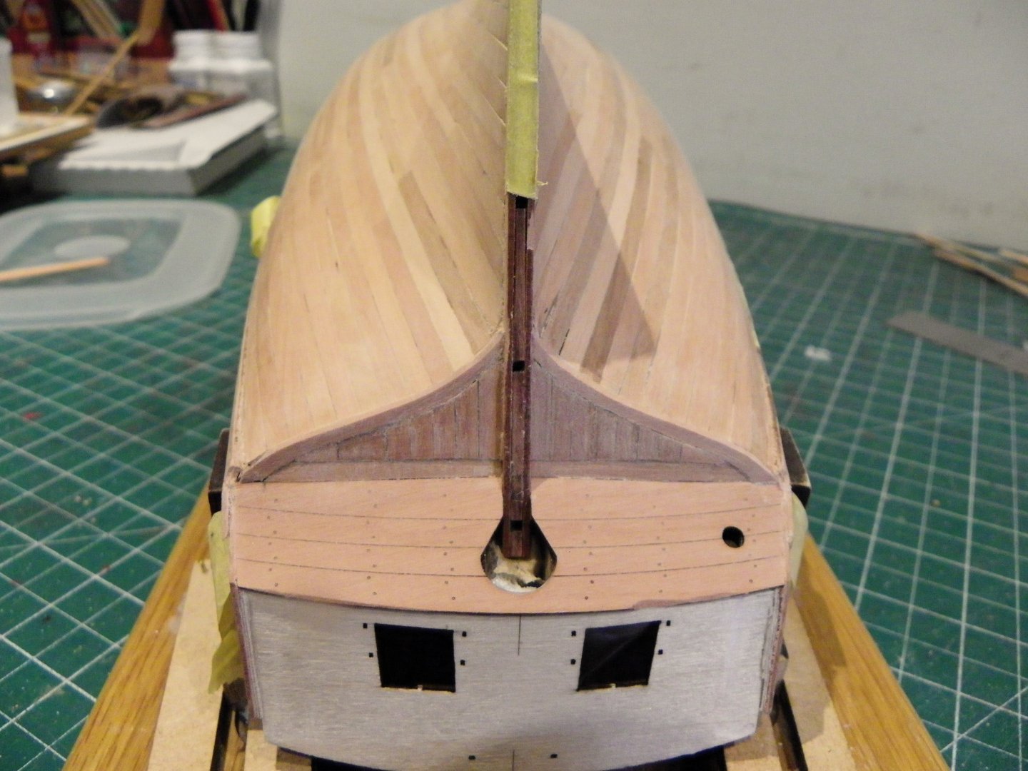
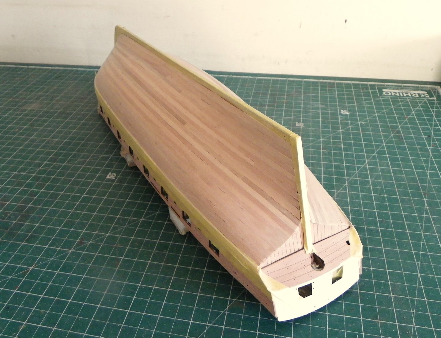
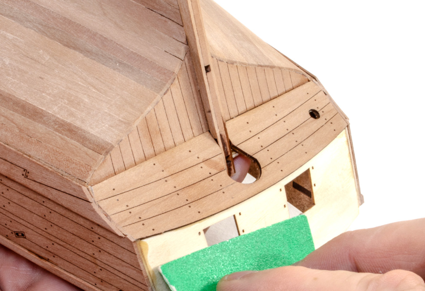
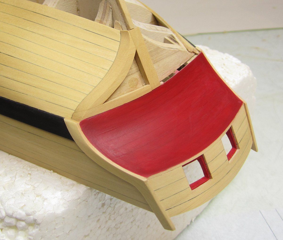
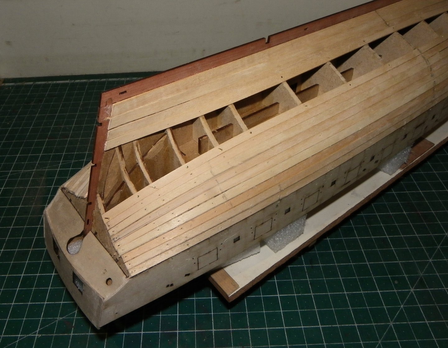
Thanks for looking in SaltyScot, early days but I think she's shaping up. Post 18 Square Tuck or what? Post 36 about planking below the lower counter has set a hare running in my mind. Harpy kit prototype build.. What we are looking at here is a Square Tuck arrangement and the idea that the hull planking with open grain ends finishing atop the vertical planking seems somewhat impractical and may simply be a kit simplification. My mind went back to my Cheerful build and the arrangement designed by Chuck, with framing for the Tuck, and boards inserted leaving no open ends. Chuck's Cheerful arrangement. I decided to use the engraved pieces for the tuck but play around with a frame arrangement that at least gives a nod to the set-up for a square tuck as seen on small vessels. 0160 0163 The frame shapes were cut out on the jigsaw and this is the arrangement very much in the rough. The hull planking will butt against the frame which will cover the grain ends, which is always good carpentry practice. I will infill with planks to sit flush with the framing. 0164 This is not a big issue in terms of the overall look of the model and the planking will proceed as per the kit arrangement. I will re-visit this once the planking has been completed and decide which version I prefer. B.E. 12/01/2025


- 332 replies
-
- 19
-
-
- Harpy
- Vanguard Models
- (and 1 more)
-
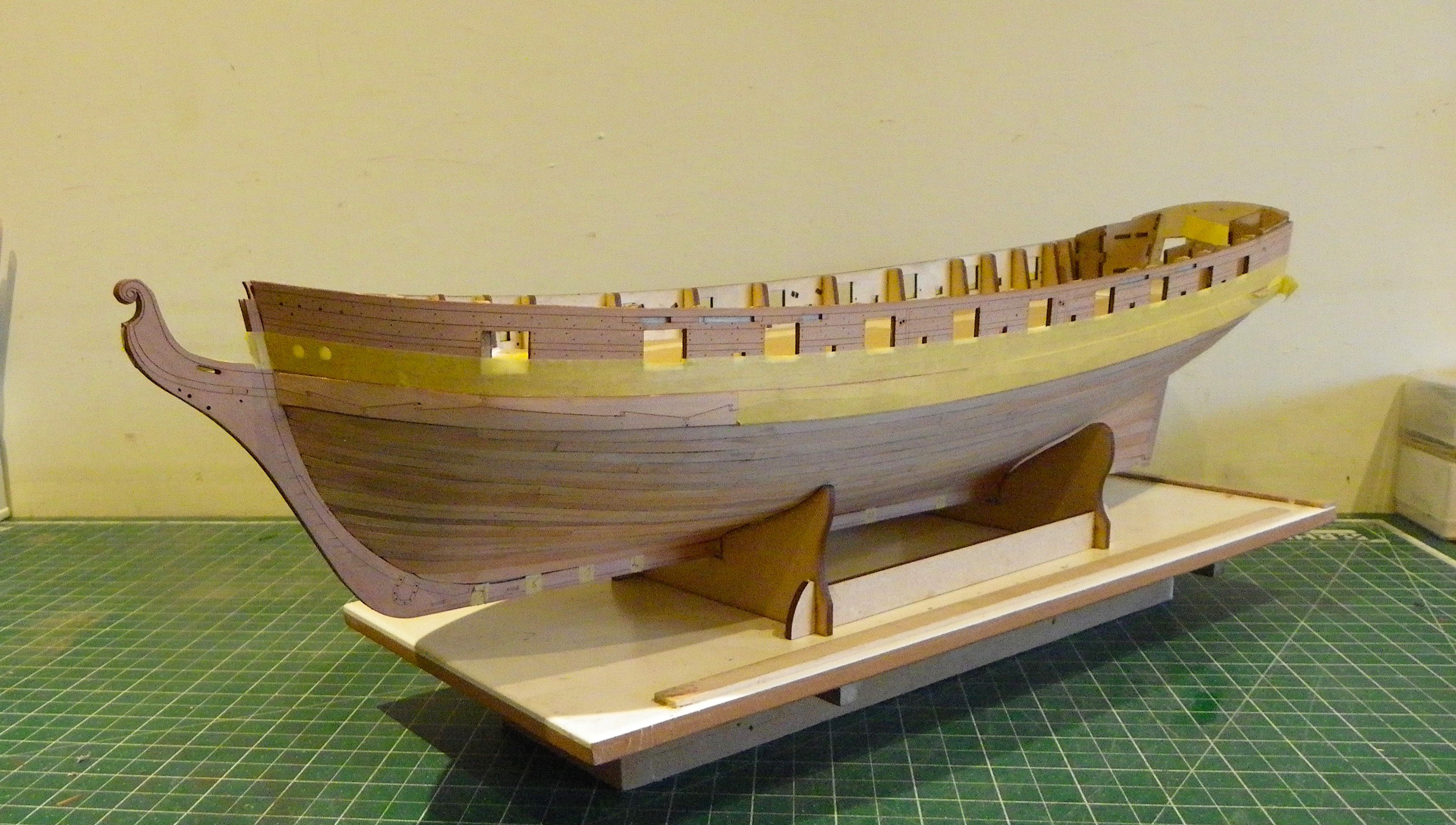
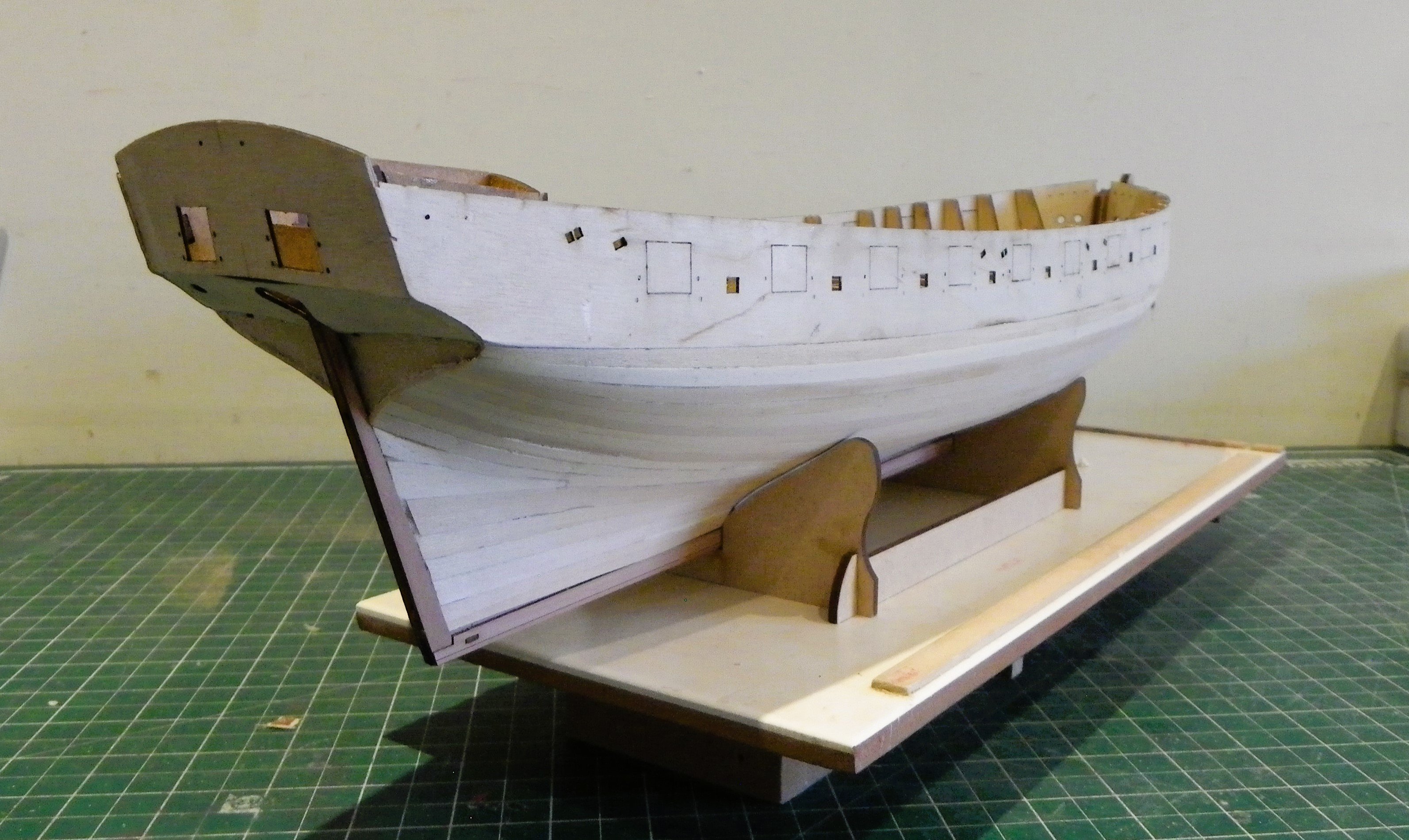
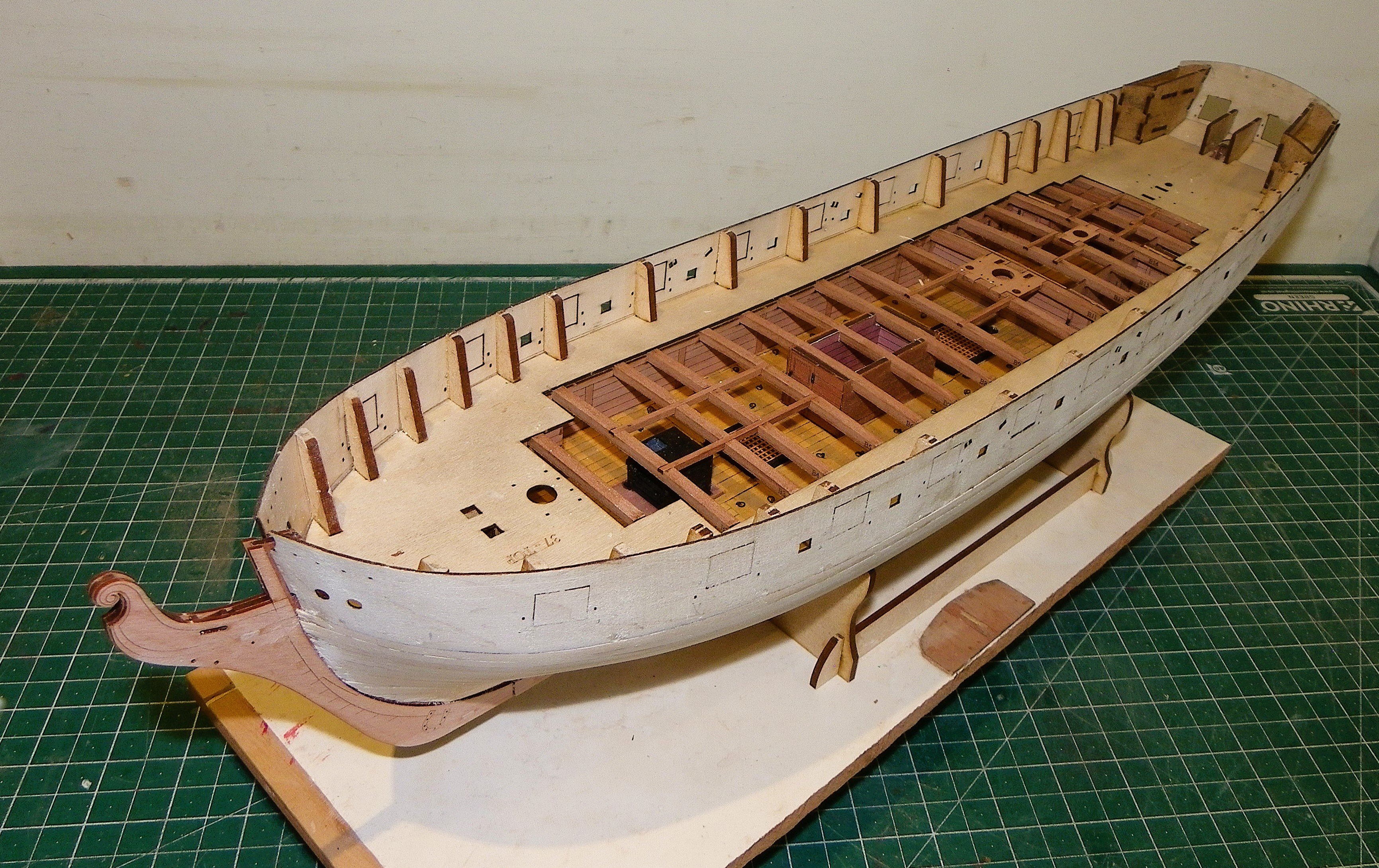
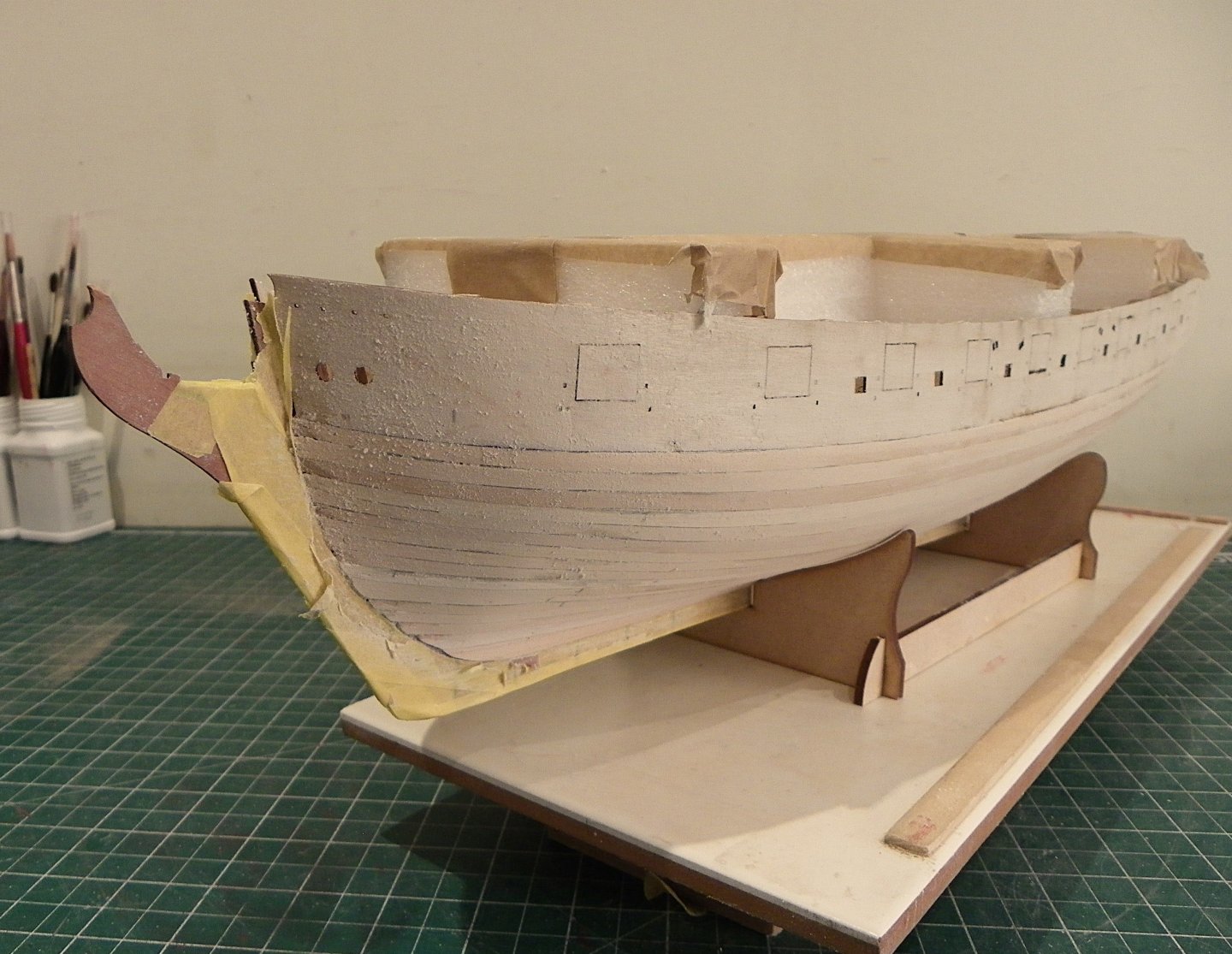
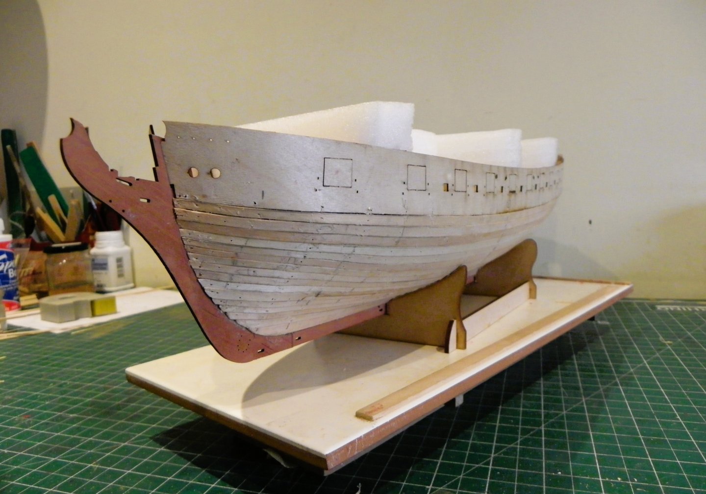
Post 17 Dressing the Hull As a break from planking the time has come to fit many of those engraved Pearwood veneers that complete the outer look of the model. These essentially replace the need for individual planking of the topsides and stern counters. I am mostly at ease with these simplifications as a similar system was used on the Sphinx model and I like the look of her. 0154 Firstly, additional veneer pieces representing the Knee of the head, including the Fiddle scroll, keel and stern post are glued and pegged into place. 0136 The stern post pieces needed a little fettling to fit. A gentle touch is required, these are fragile parts. 0130 0139 0148 0142 I have not yet fitted the pre-printed lower stern boards, I have something in mind for that area. B.E. 11/01/2025


- 332 replies
-
- 26
-
-
- Harpy
- Vanguard Models
- (and 1 more)
-
Preferably on top of the Pennines with the wind at your back.😃
- 332 replies
-
- 3
-

-
-
- Harpy
- Vanguard Models
- (and 1 more)
-
Thank you Glenn, I've had the tin for years - it says on the label Manufactured for J Perkins. They are a very old Model Company, and they still supply it. Thoroughly nasty stuff, care needed when using it. B.E.
- 332 replies
-
- 3
-
-
-
- Harpy
- Vanguard Models
- (and 1 more)
-
Thanks for the 'heads up' James, I wish I'd known that an hour ago ! 😉 B.E.
-
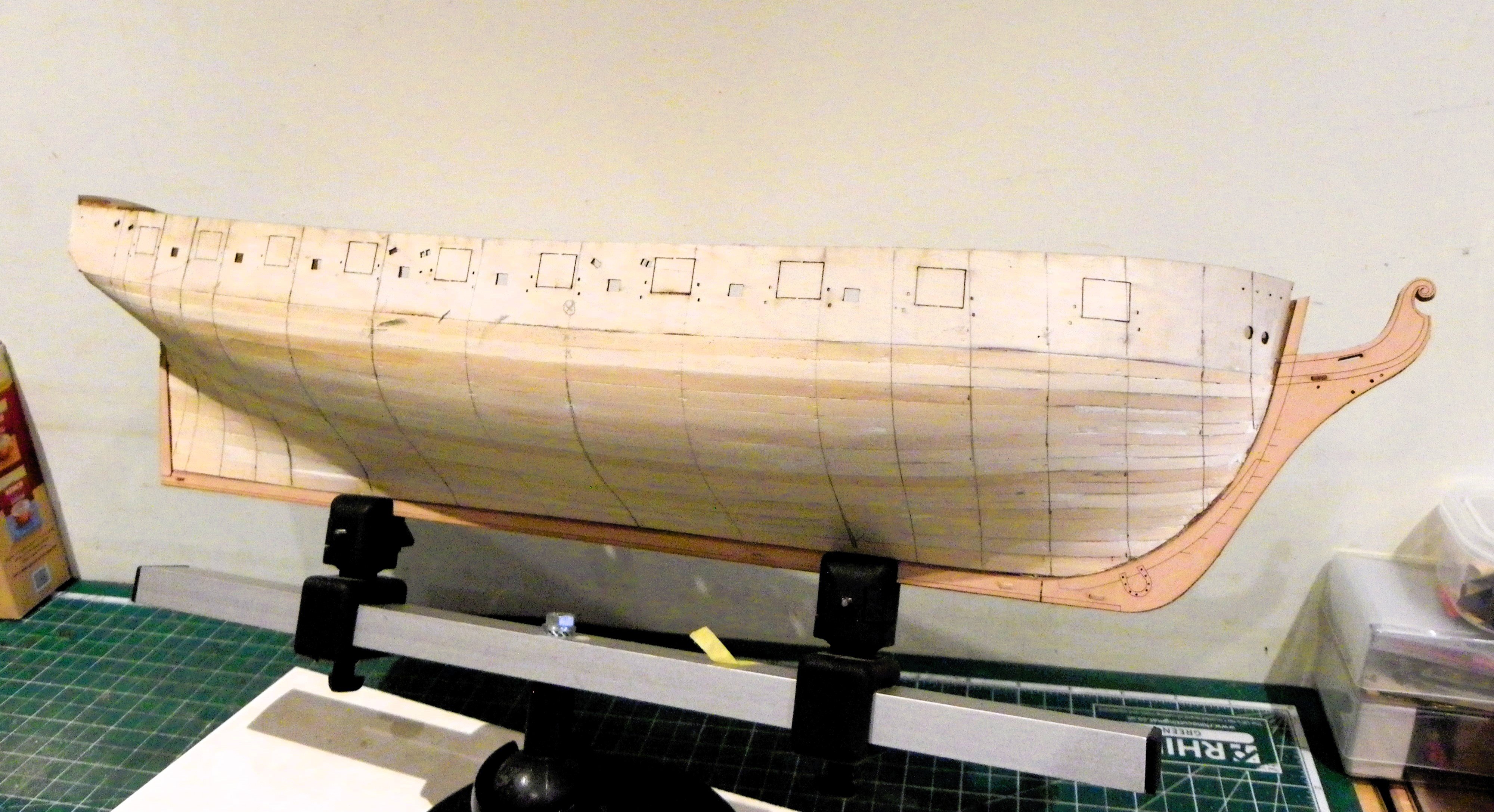
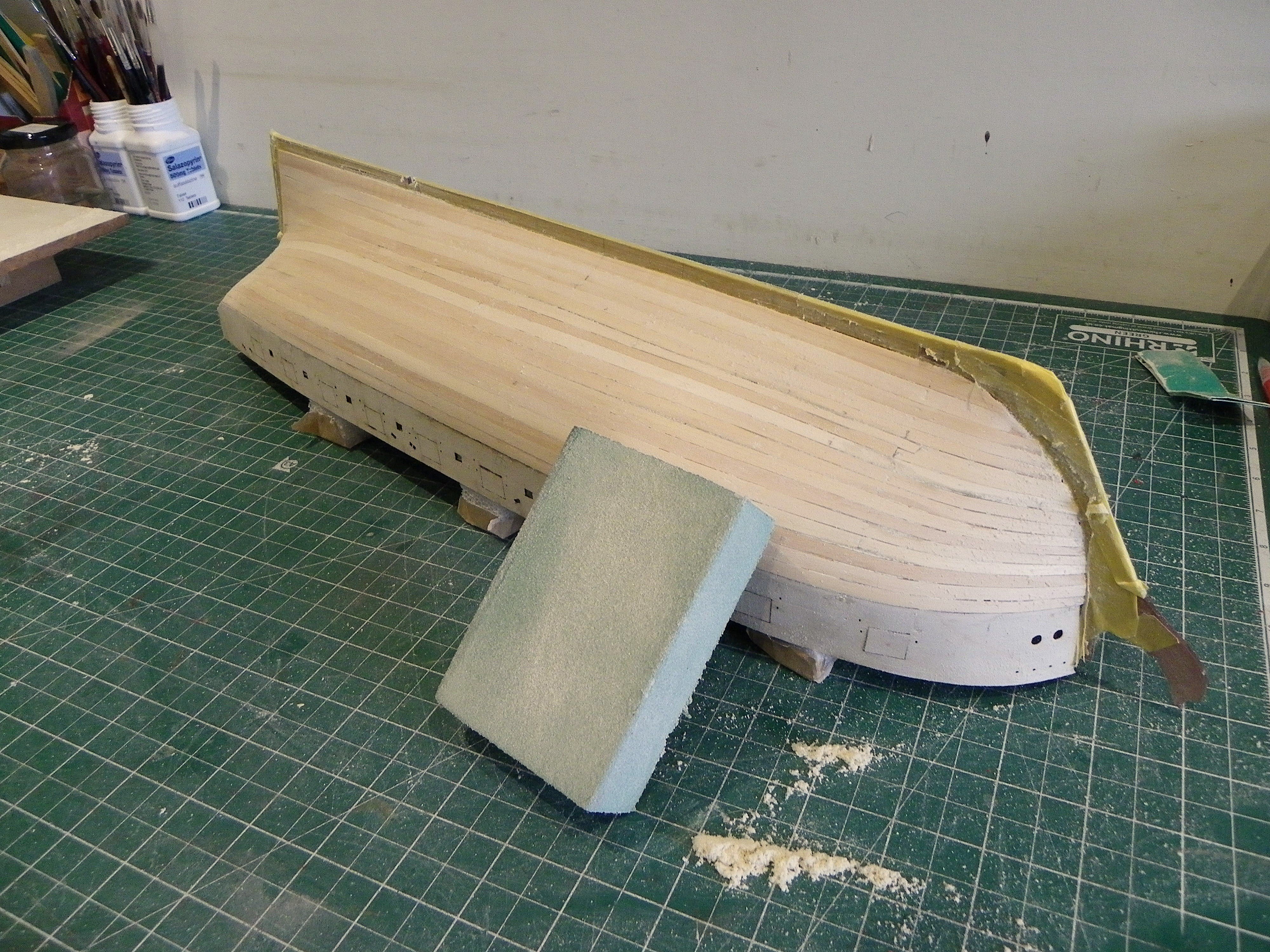
Post 16 Sanding the hull For this I am using flexible sanding blocks and papers. I start with 120 grade papers. 0105 I decided not to use the B&D Mouse sander, seemed overkill on a small hull like this and Limewood is fairly soft to sand. Indefatigable it ain’t. Where there were hair gaps between the strakes pva was run in, sand dust sprinkled on, and then sanded in. 0121 I finished off with 180 paper. 0122 0123 0119 0120 0107 The hull seems to have scrubbed up nicely, I’m still amazed when I reach this point that it looks as good as it does given the state before sanding, but the display planking will be a job of a different calibre. The next stage involves fitting the lower stern boards. 0115 These are pre-printed 0.8mm patterns that should just sit above the first planking layer, presumably to meet the second Pear layer. 0116 Worth checking before the hull sanding stuff is put away. 0112 0126 The sanding job has taken around 3 hours, but I will review my efforts tomorrow as a final check. I will apply sanding sealer to the hull but it’s far too cold in these ‘ere parts for outdoor work, so that will have to wait. B.E. 09/01/2025


- 332 replies
-
- 22
-
-
- Harpy
- Vanguard Models
- (and 1 more)
-
You're doing a fine job on her, looking very good. Great to see that you have a new dockyard companion, having a new pup does help ease the loss of a much missed friend. B.E.
-
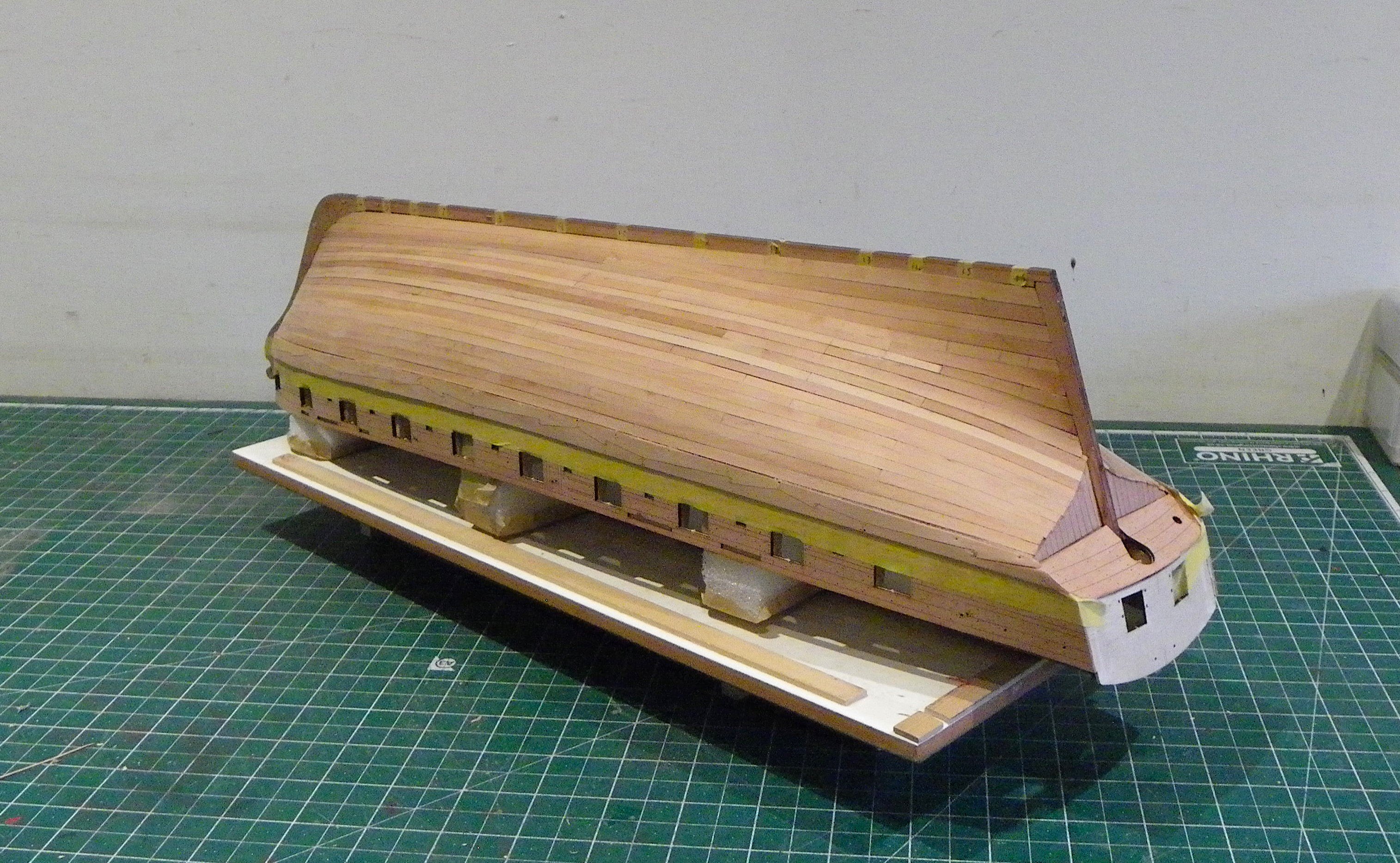
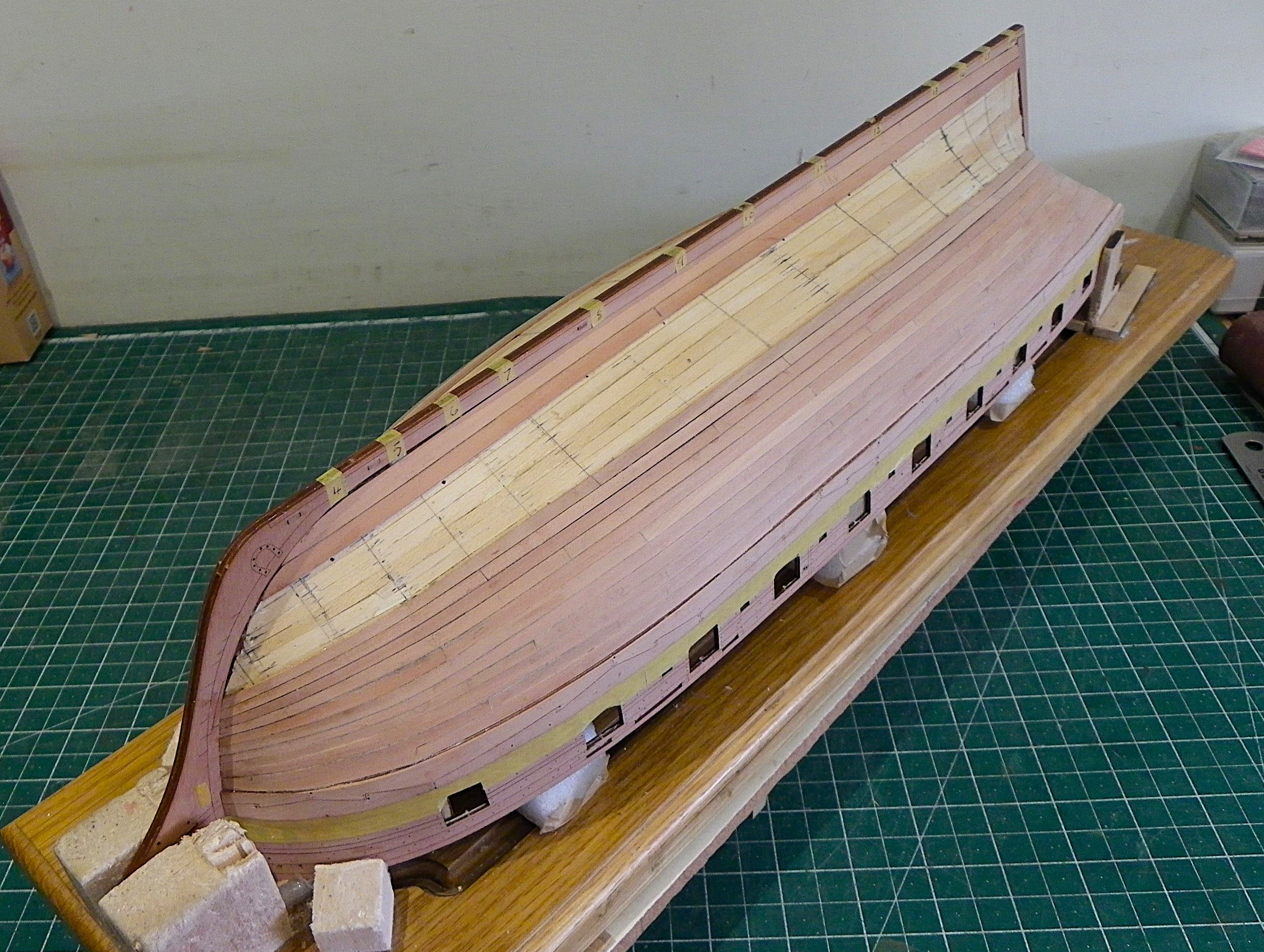
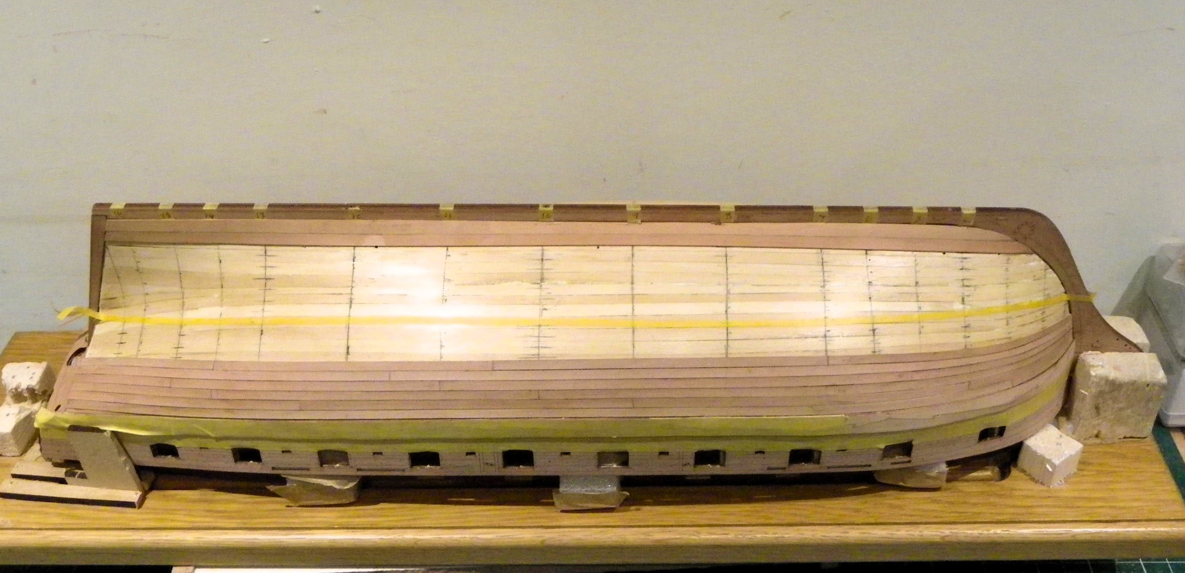
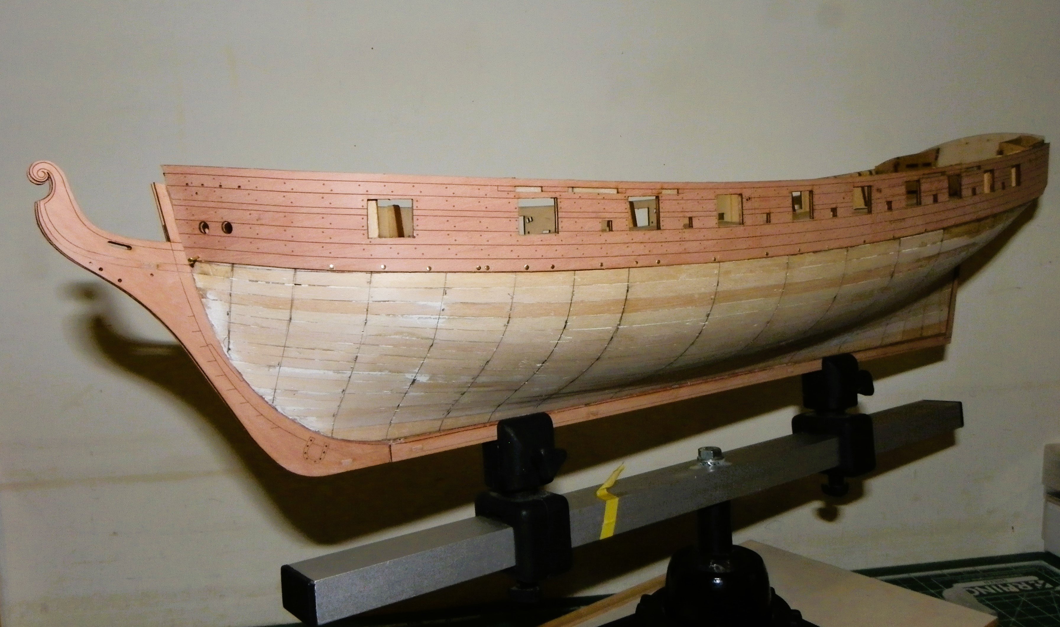
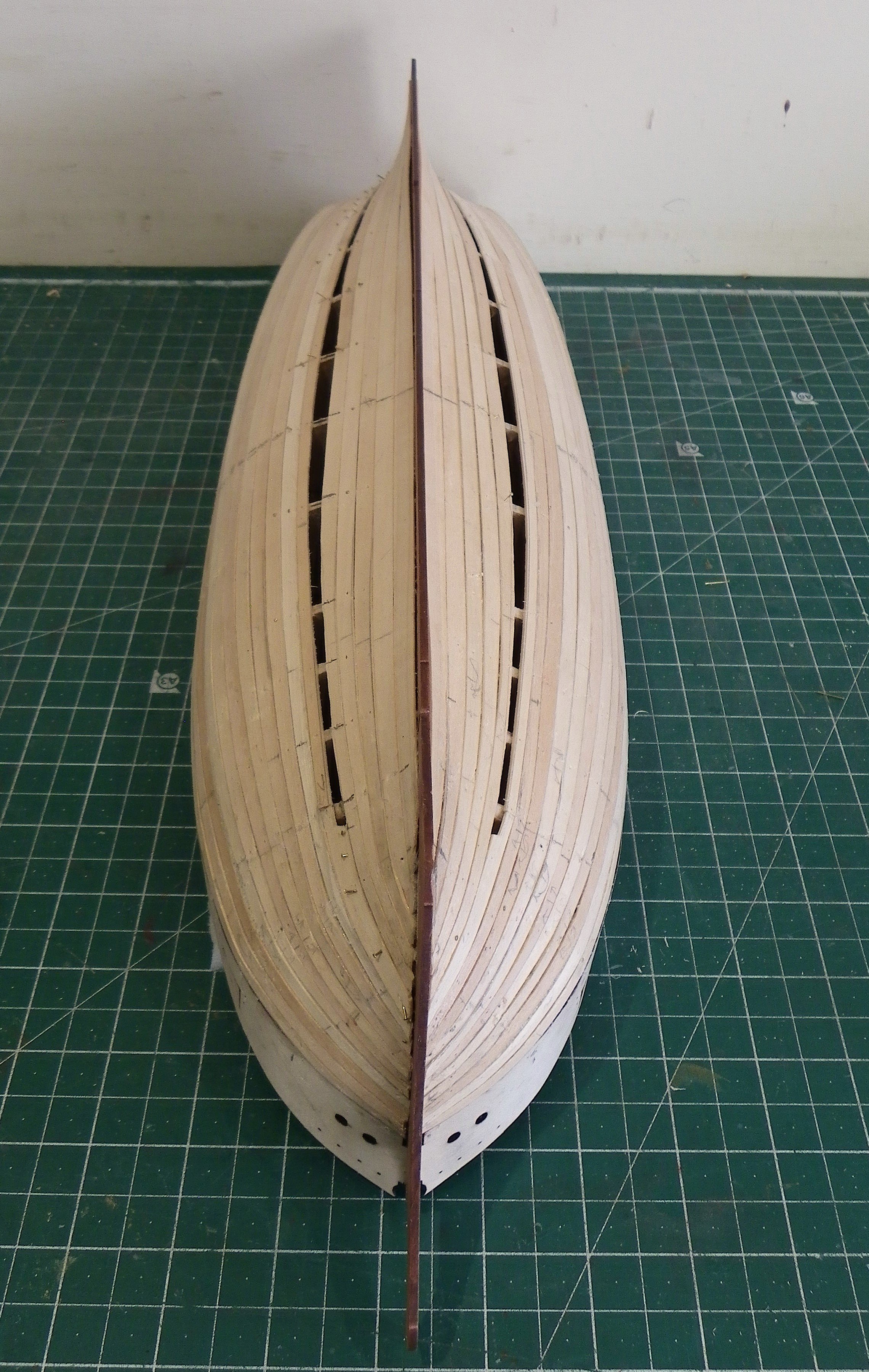
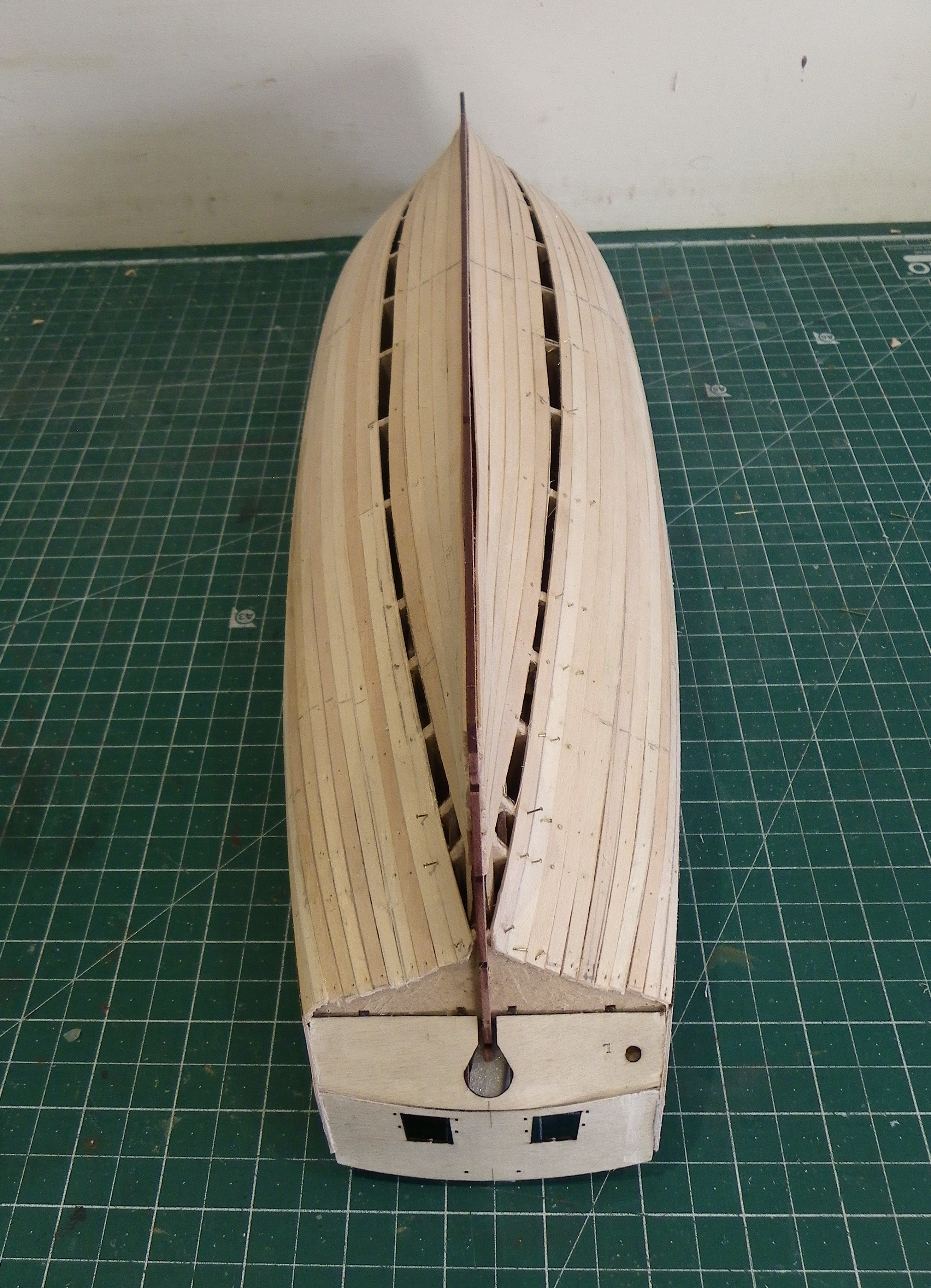
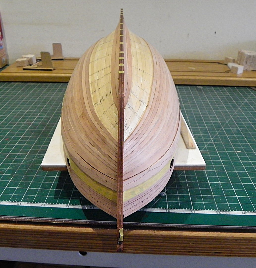
Post 15 Completion of first planking I am now planking alternate strakes from wale down and keel up. 071 My usual approach is to get a final spiled plank beneath the round of the hull. 078 As I proceed, I can see that the stern area would require more planks than the standard 5mm midships planks, resulting in the need of several stealers to fill in. As it turned out I‘ve needed to adopt a combination of techniques to get the hull planked. Tapering, Edge bending, spiling, drop planks, and even a stealer at the stern. 086 088 I used a drop plank at this point. 090 091 096 093 The final piece of the jigsaw is a stealer and the first planking is complete. 097 Note; the stealer doesn’t end in a point but is squared off and cut into the adjoining planks against a frame. Not critical on a first layer, but it should be the arrangement on a show layer should stealers be required. 0100 I am fairly well content at this point, not an arrangement I would accept as a single planking display, but as a base for the second Hardwood layer it is fine. 0104 I am pleased to note that even at this rough stage the hull conforms well to the build cradle. Time to clean up the hull. B.E. 08/01/2025


- 332 replies
-
- 26
-
-
- Harpy
- Vanguard Models
- (and 1 more)