.JPG.ca33079f5815b861e67b9c2cccd37982.JPG)

Blue Ensign
-
Posts
4,564 -
Joined
-
Last visited
Content Type
Profiles
Forums
Gallery
Events
Everything posted by Blue Ensign
-
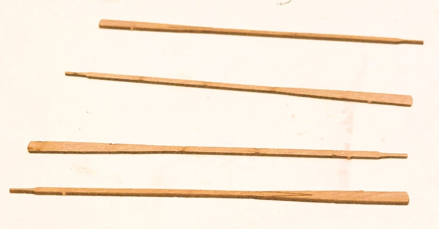
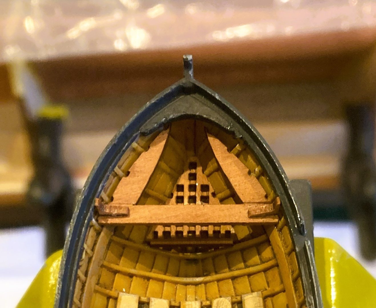
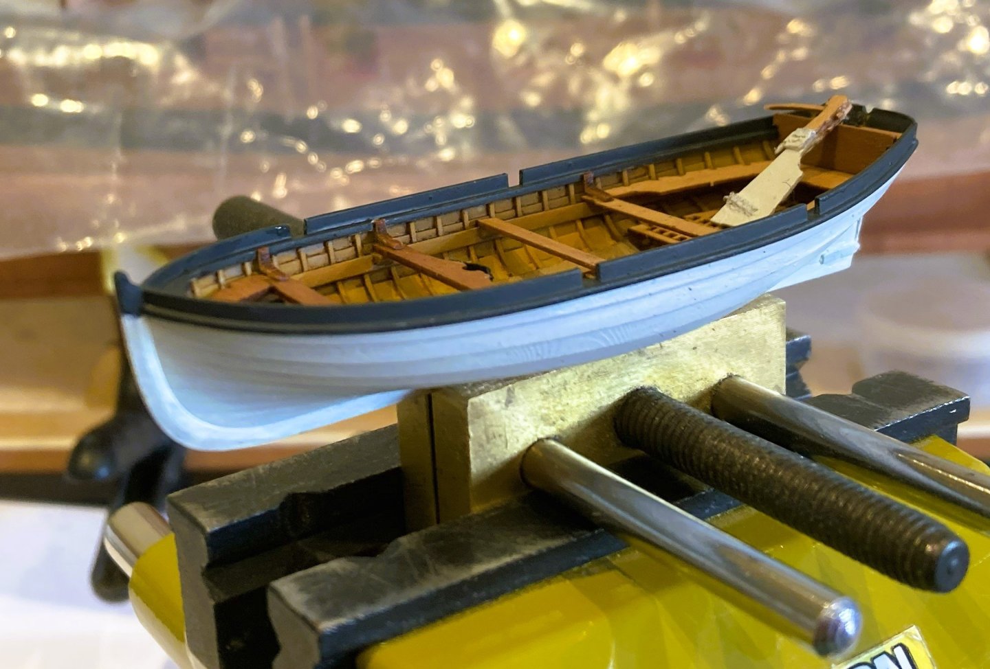
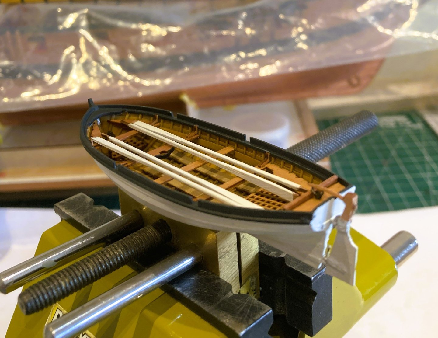
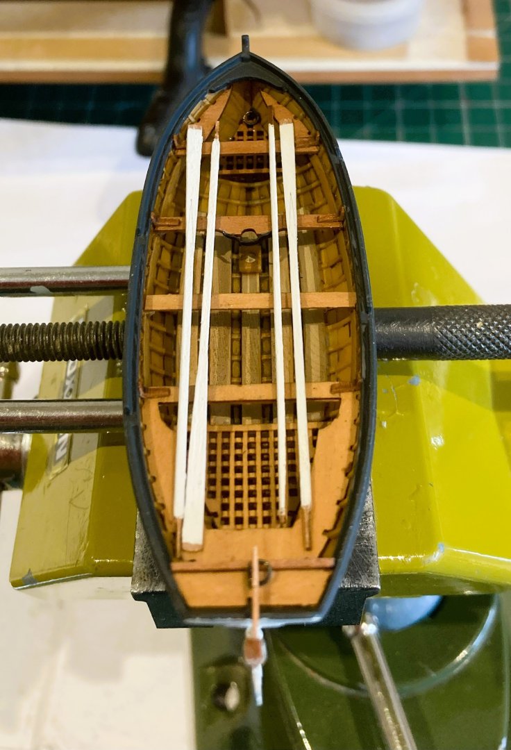
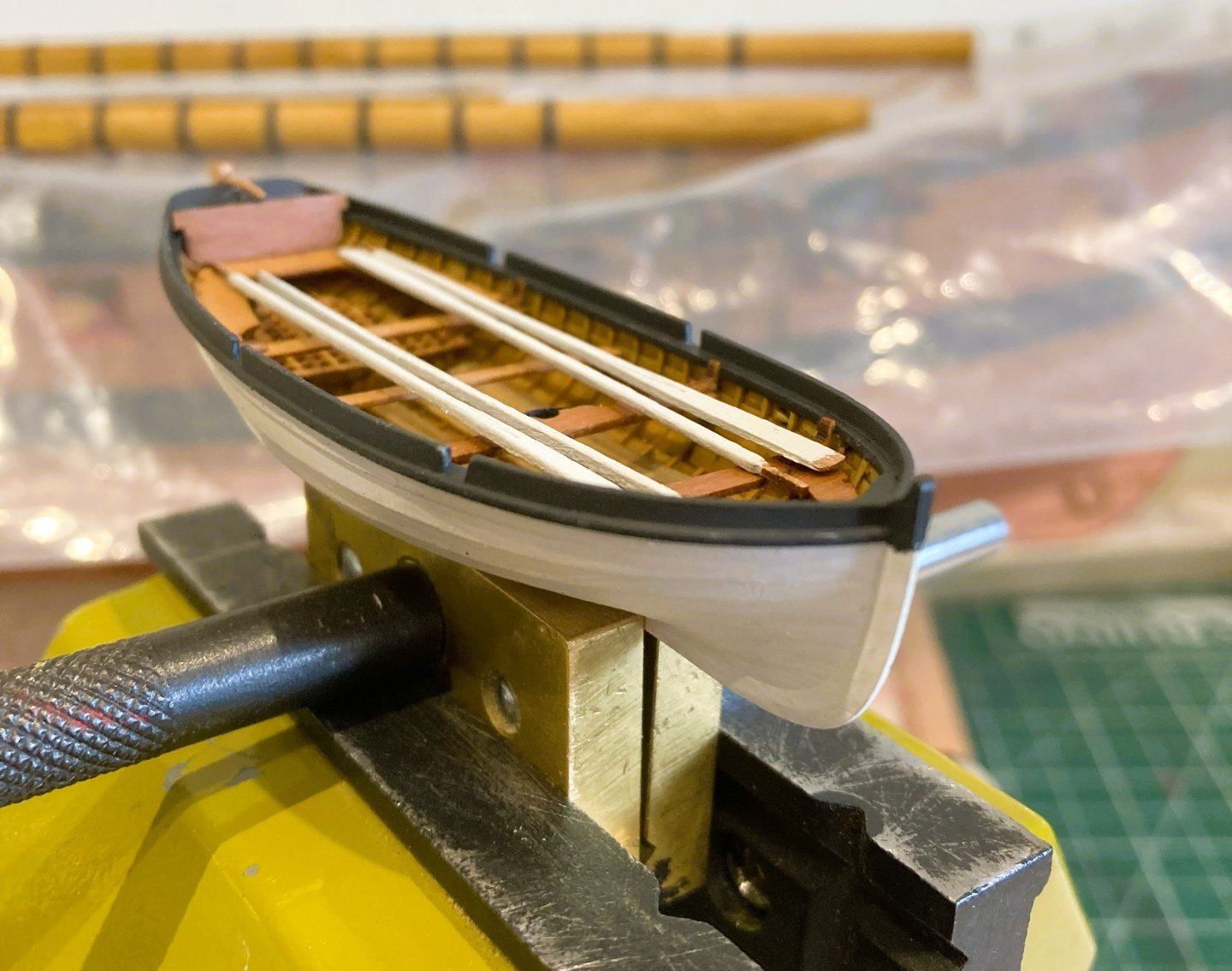
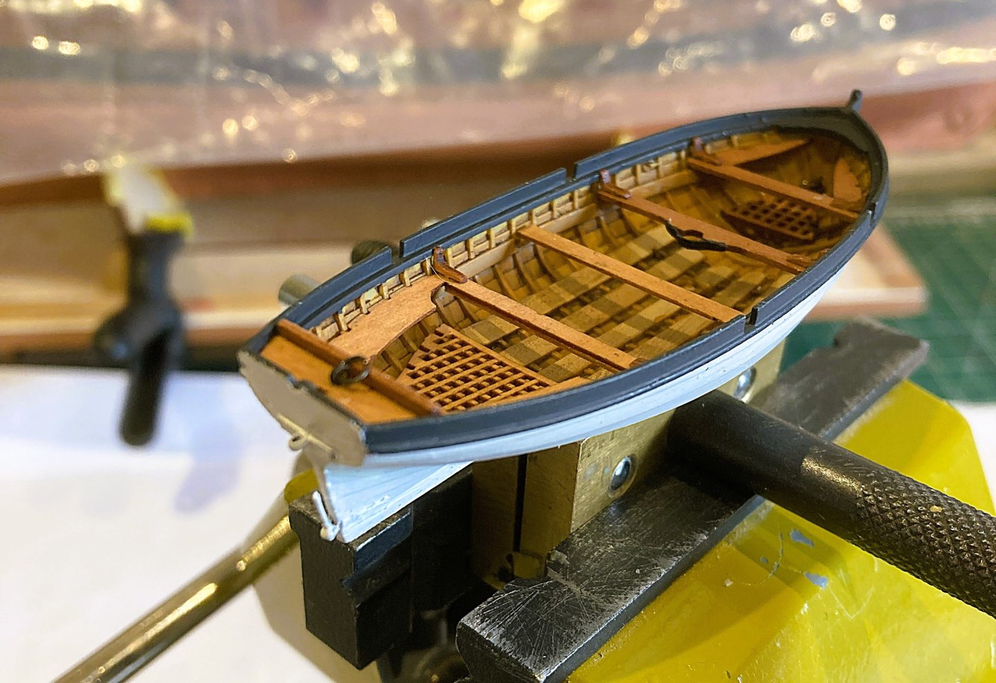
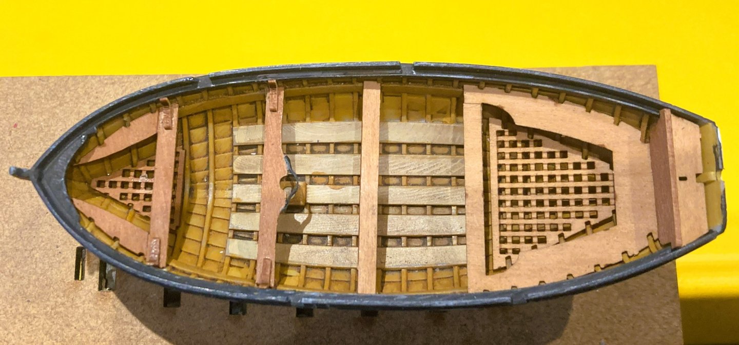
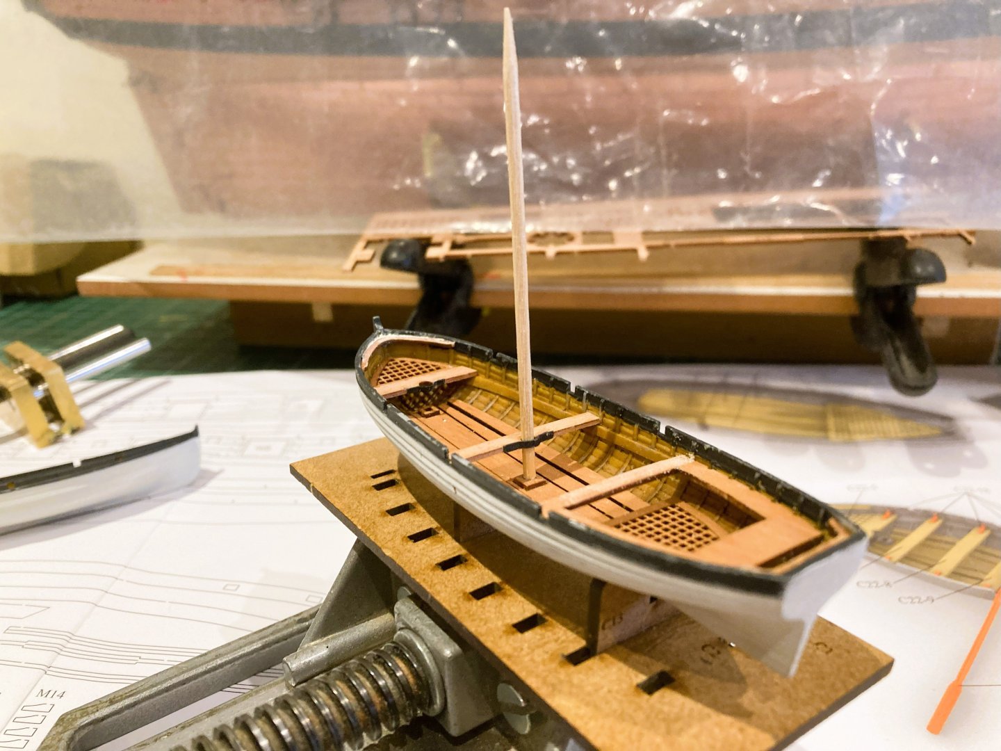
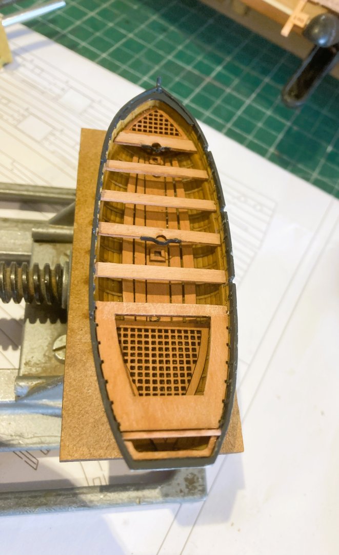
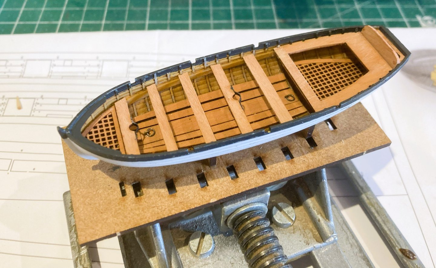
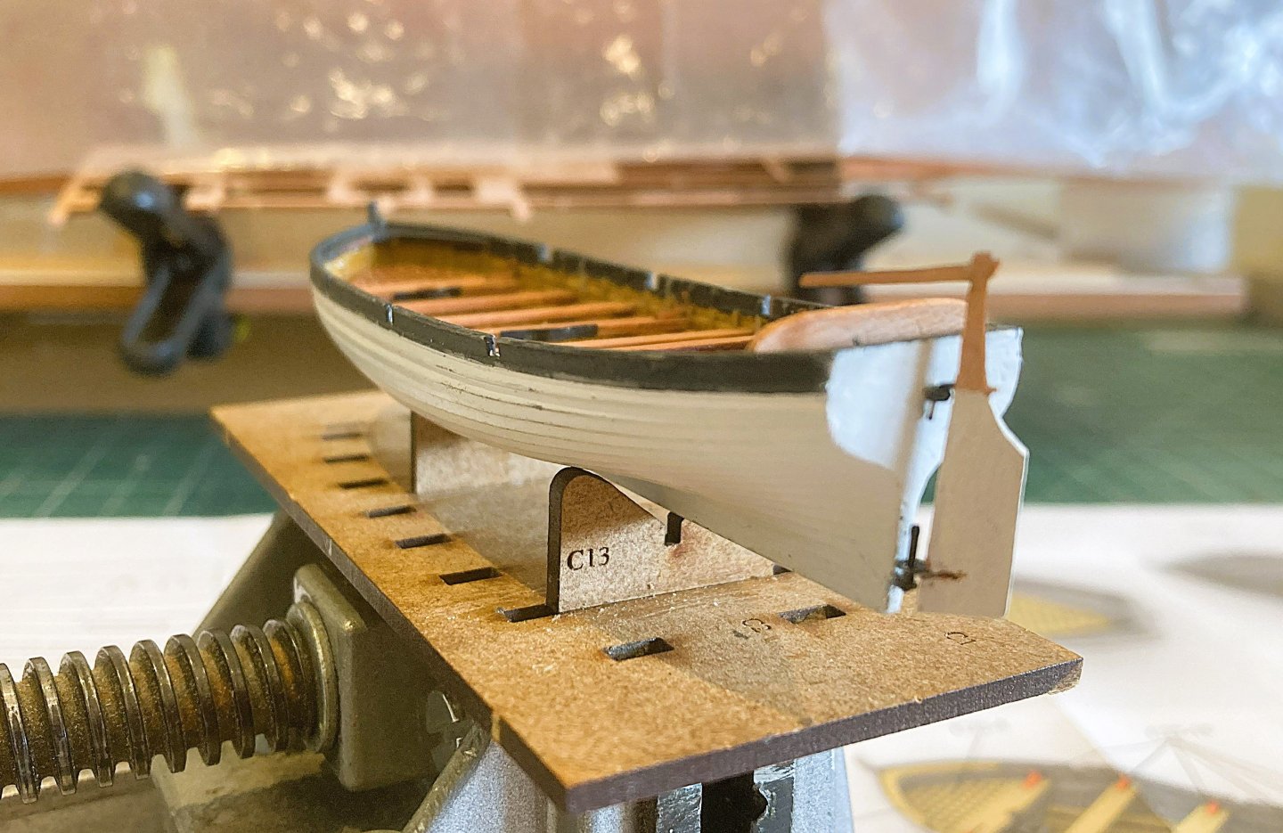
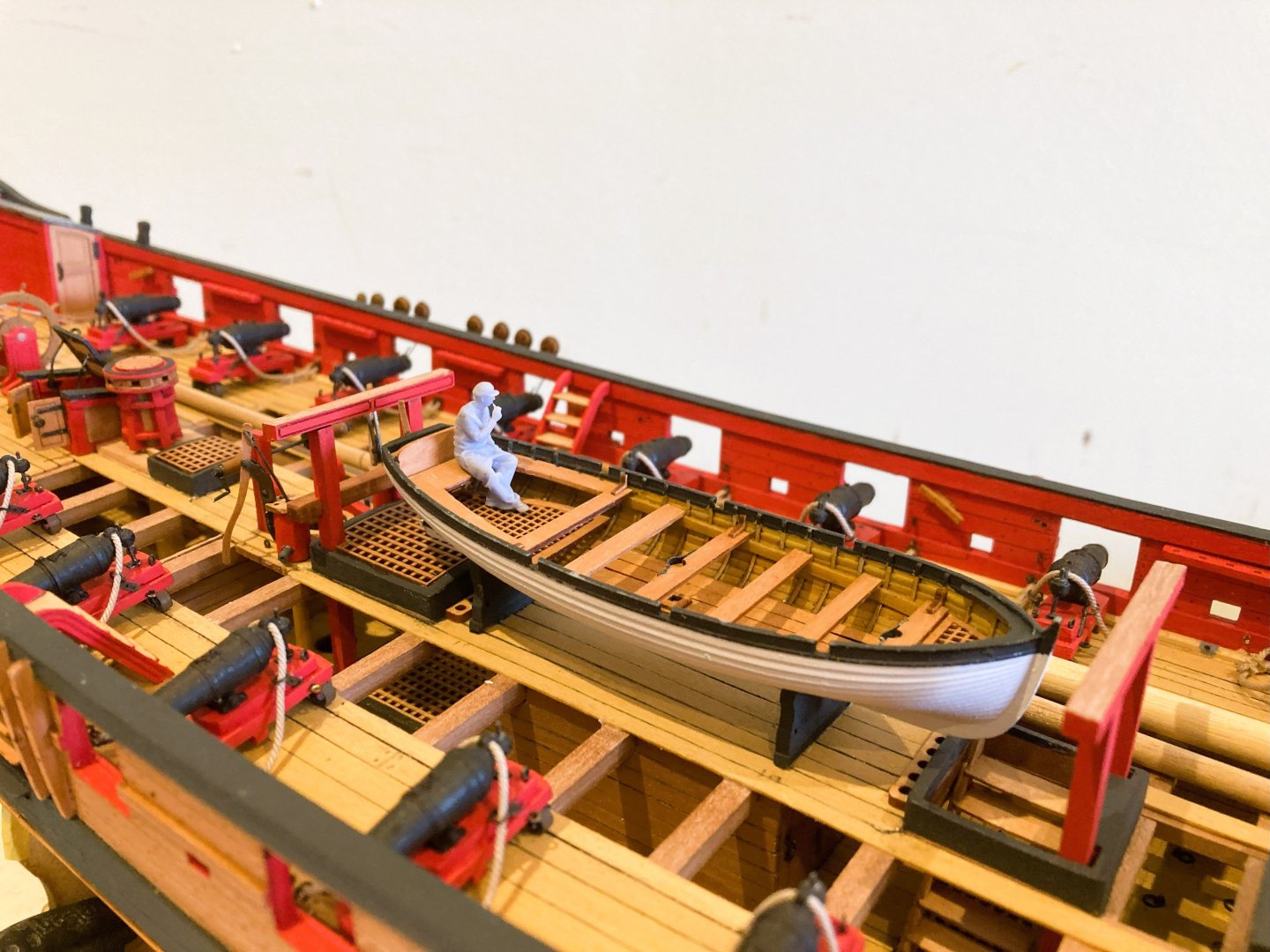
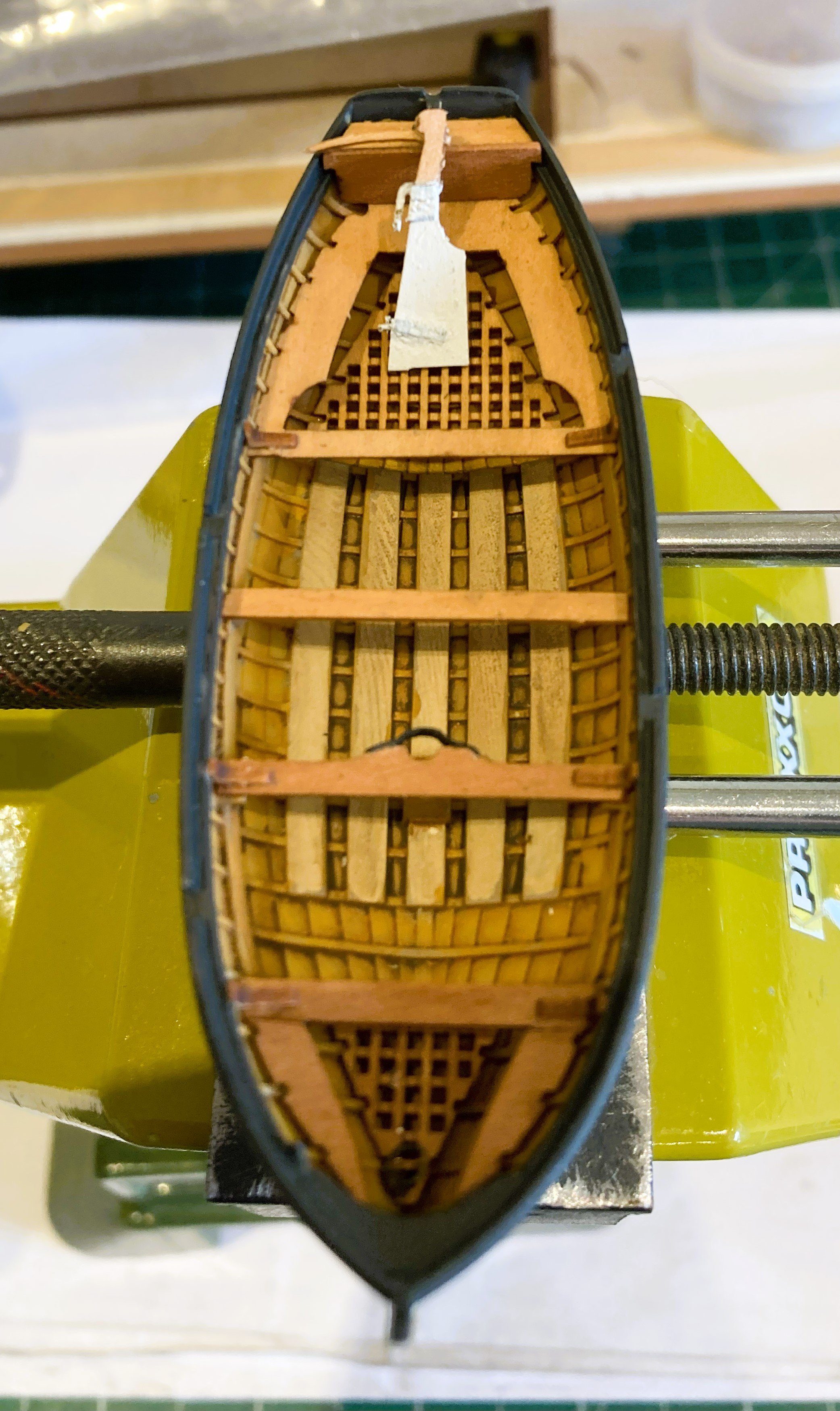
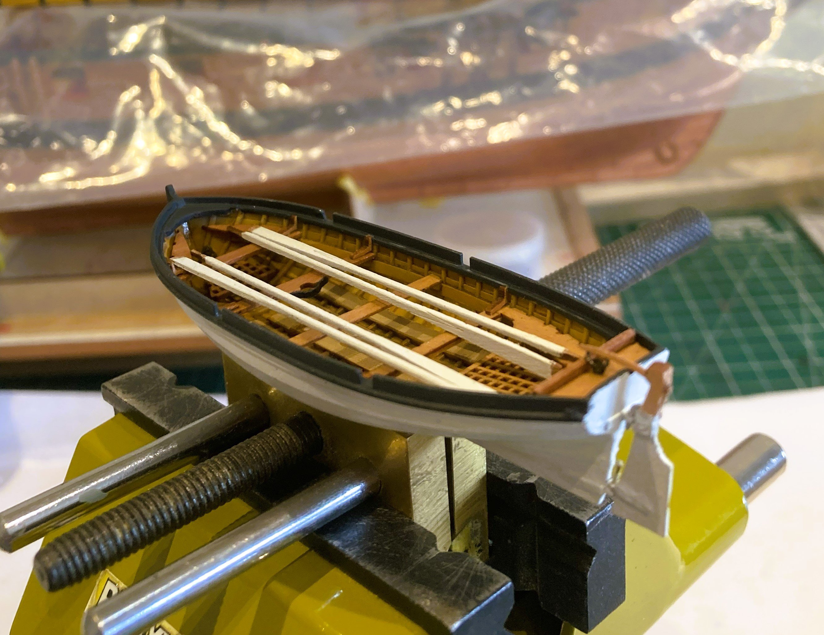
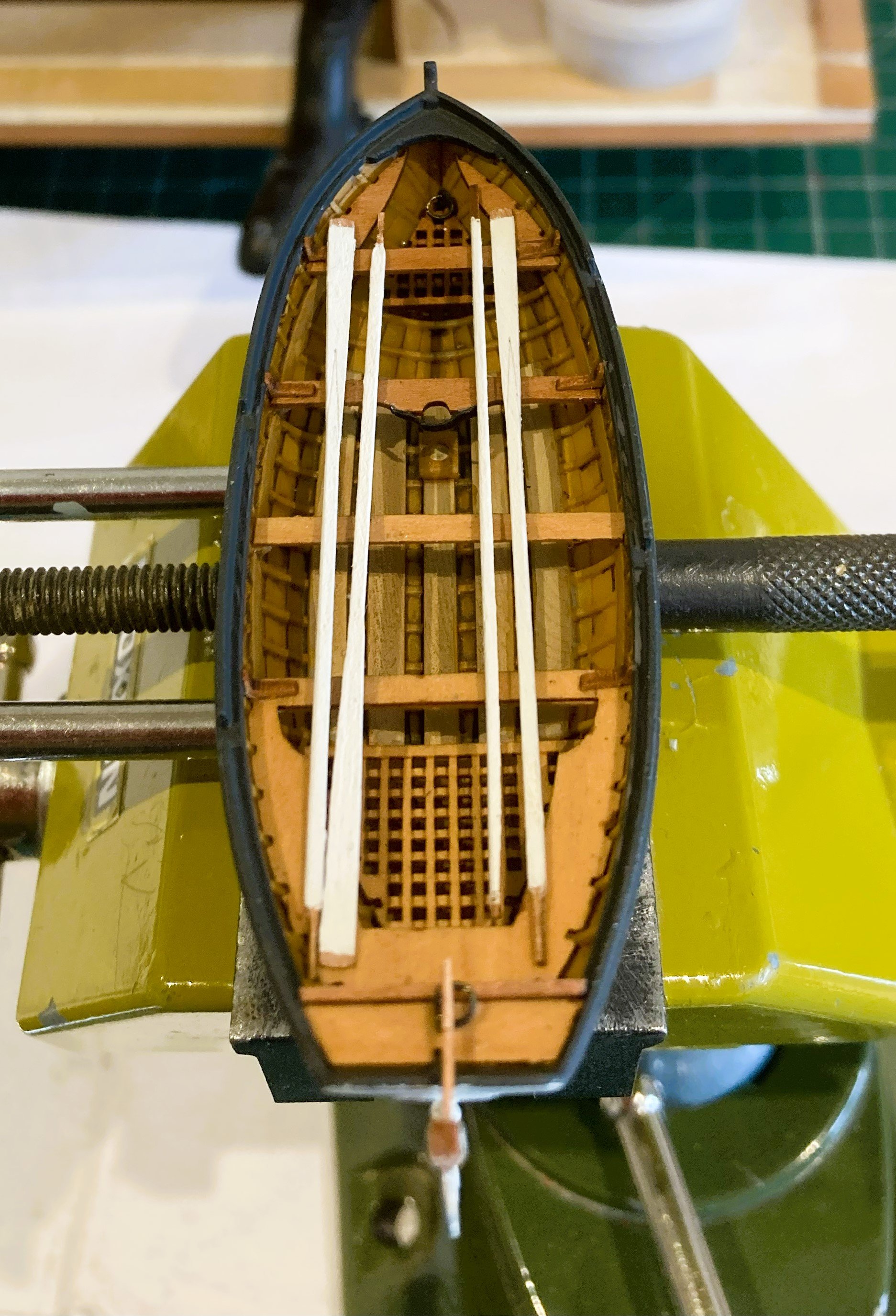
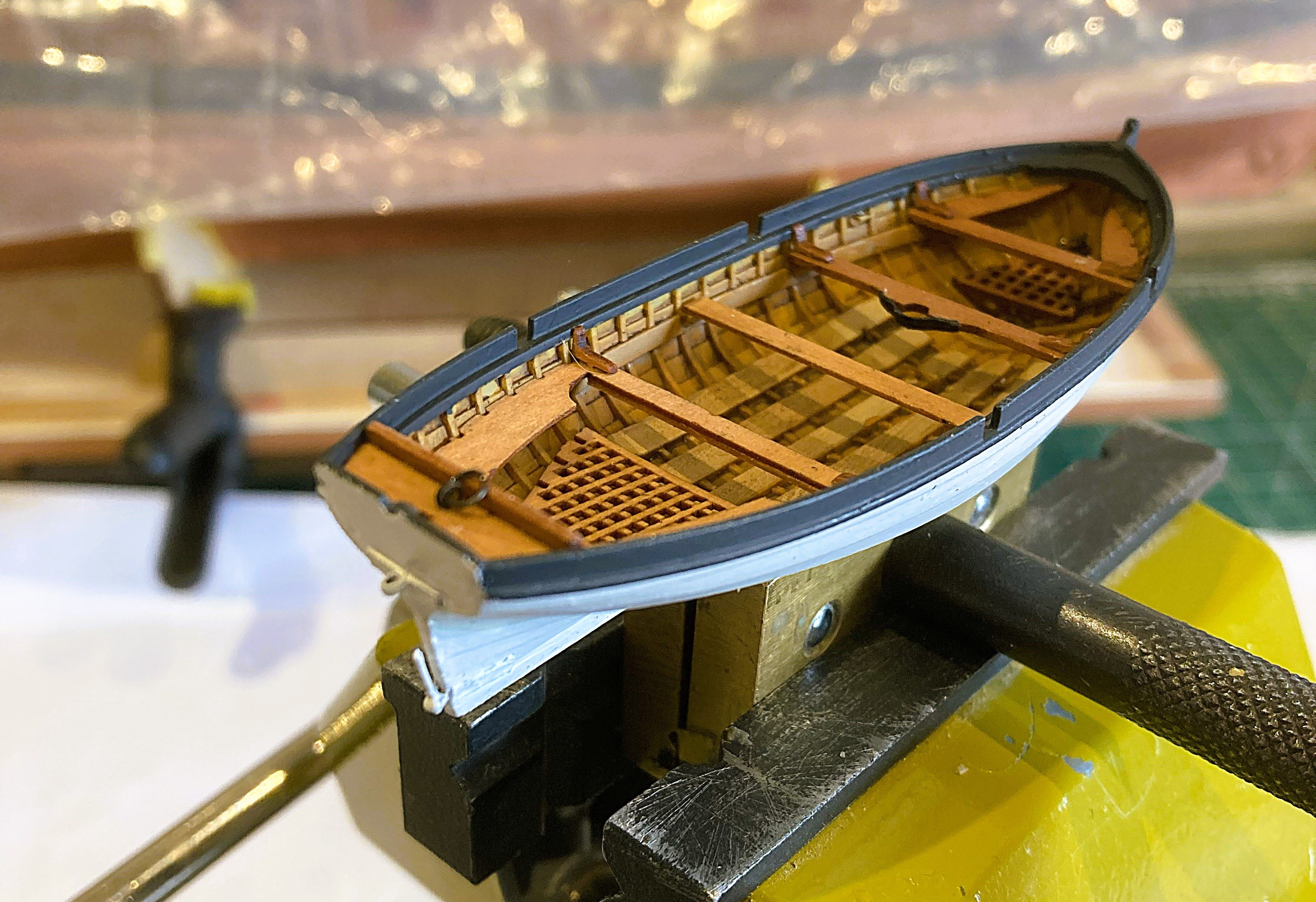
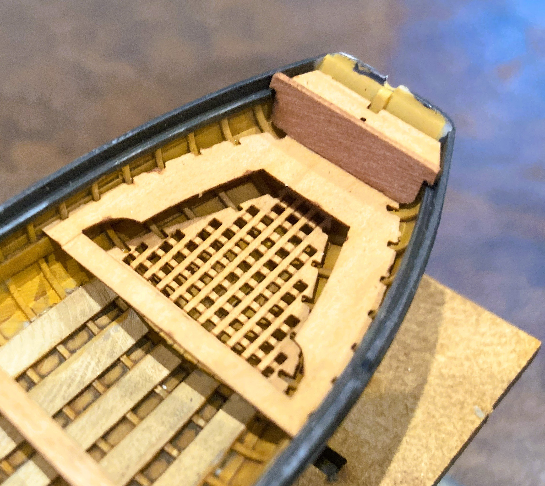
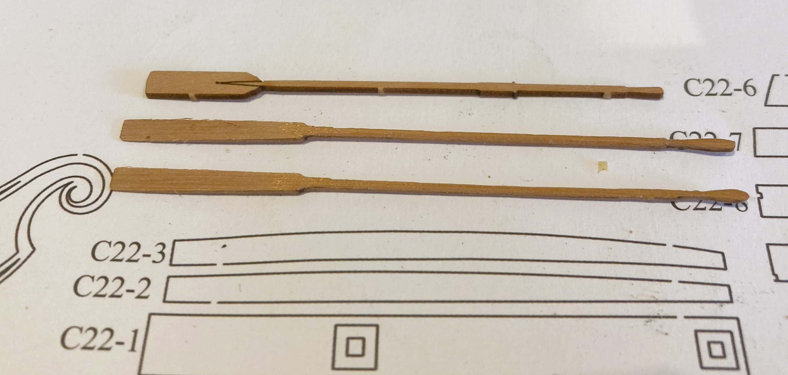
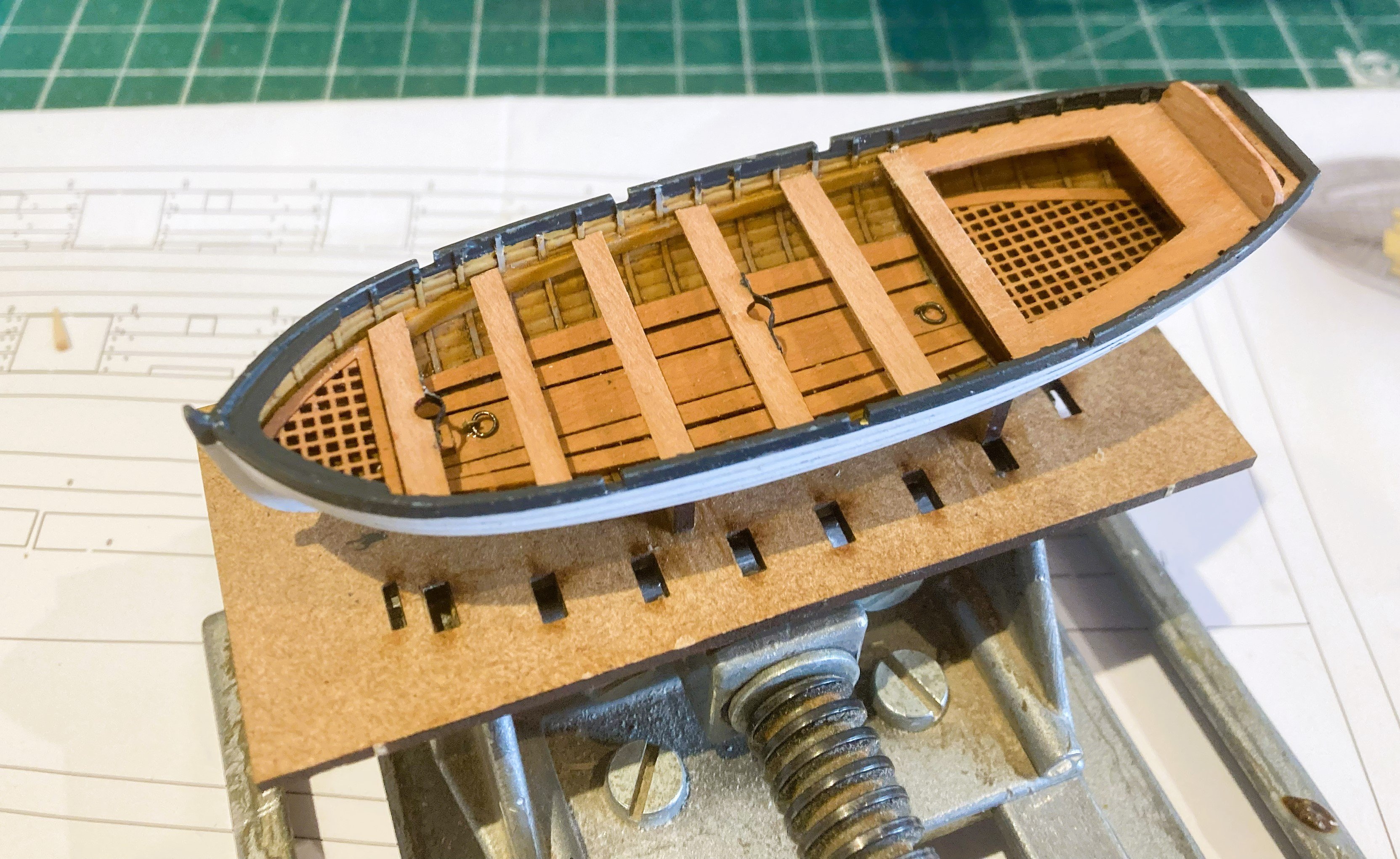
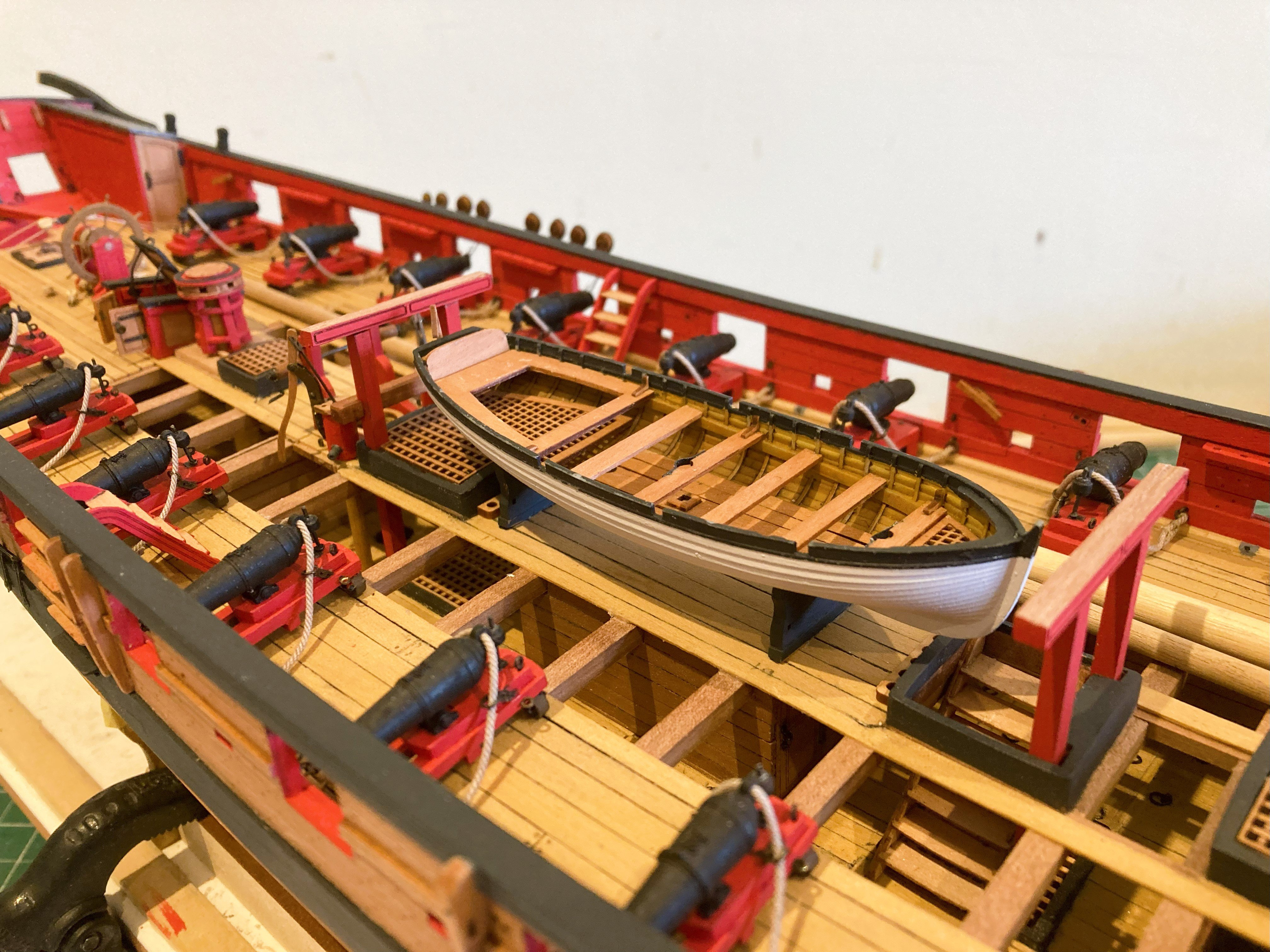
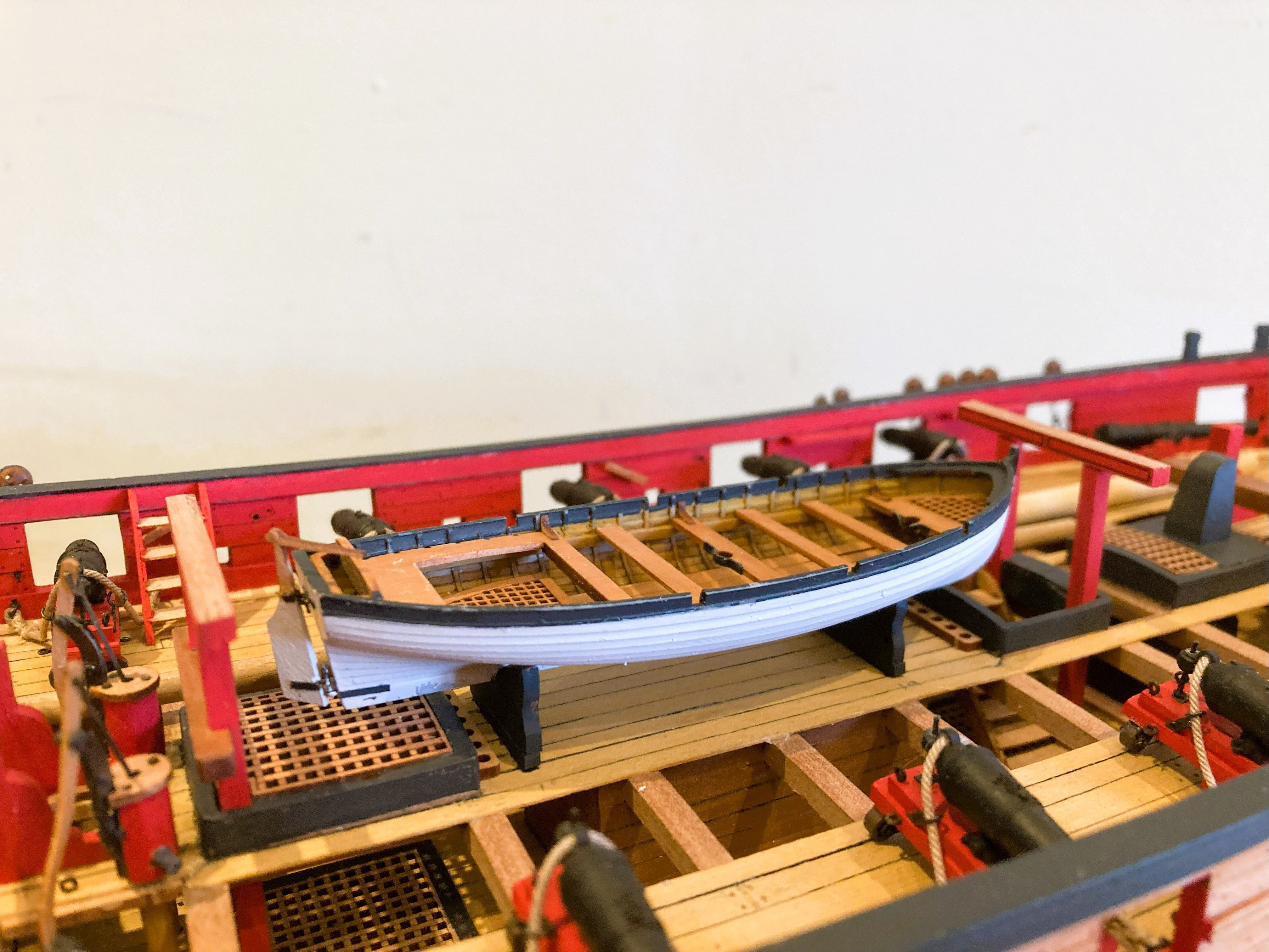
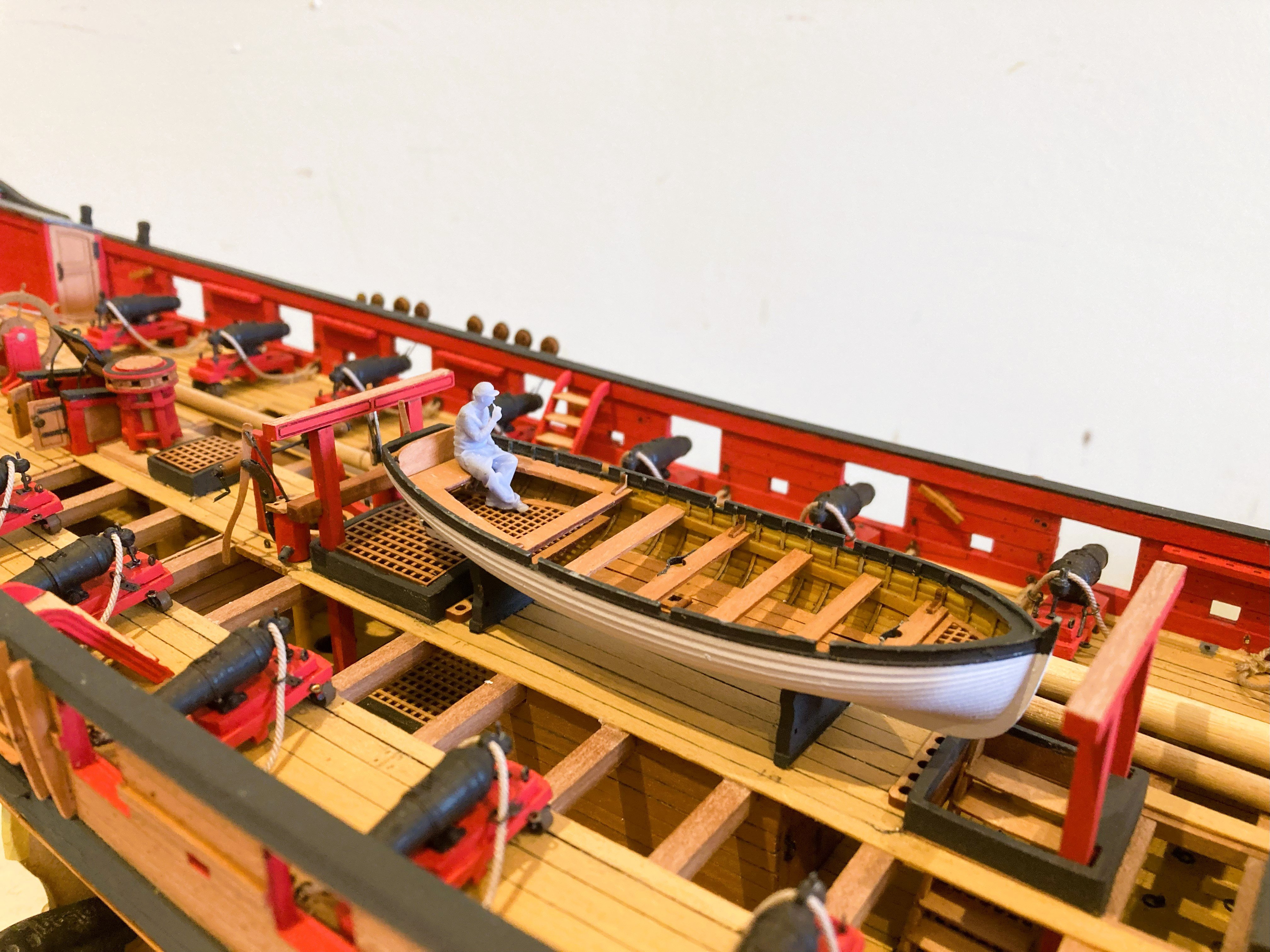
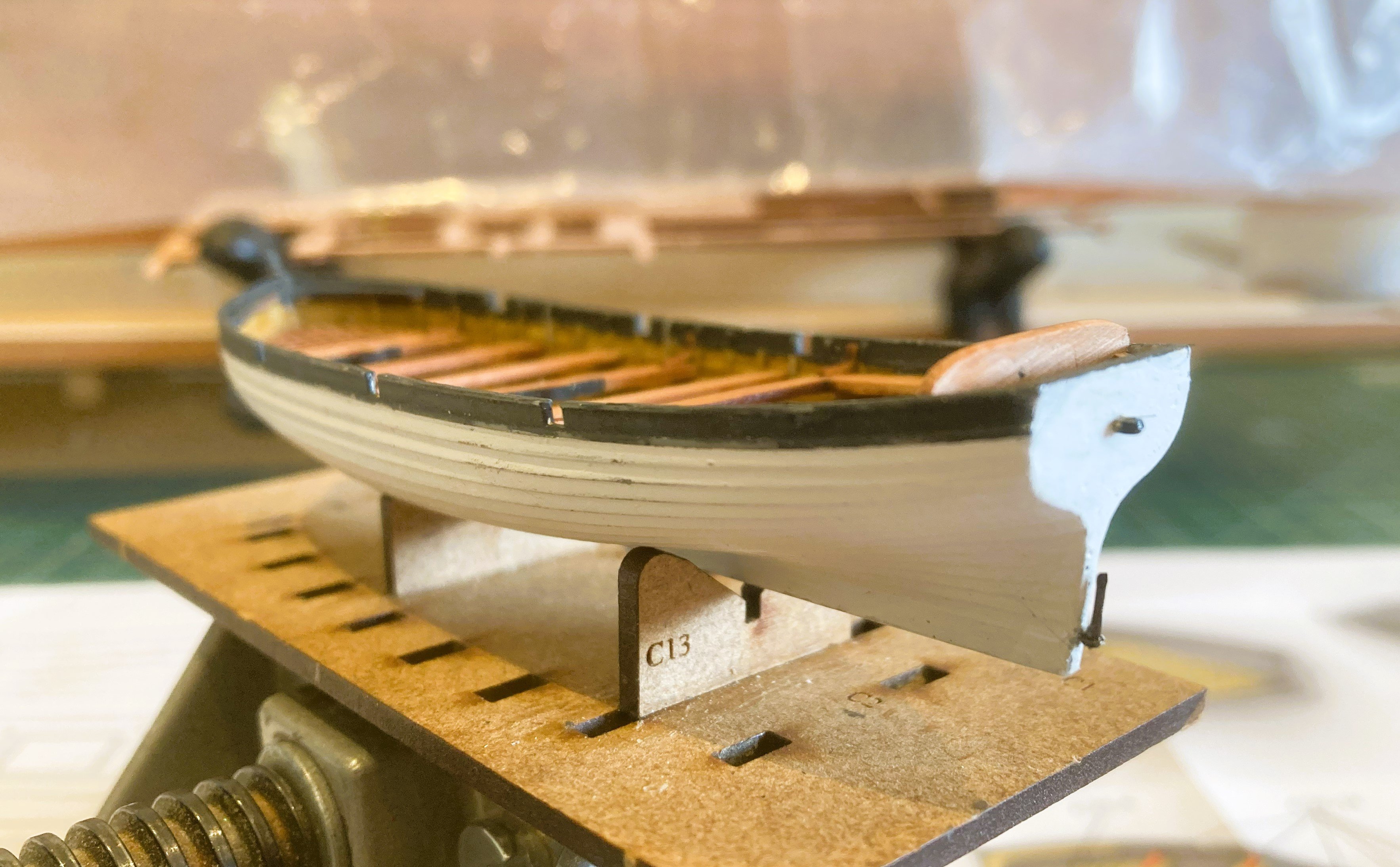
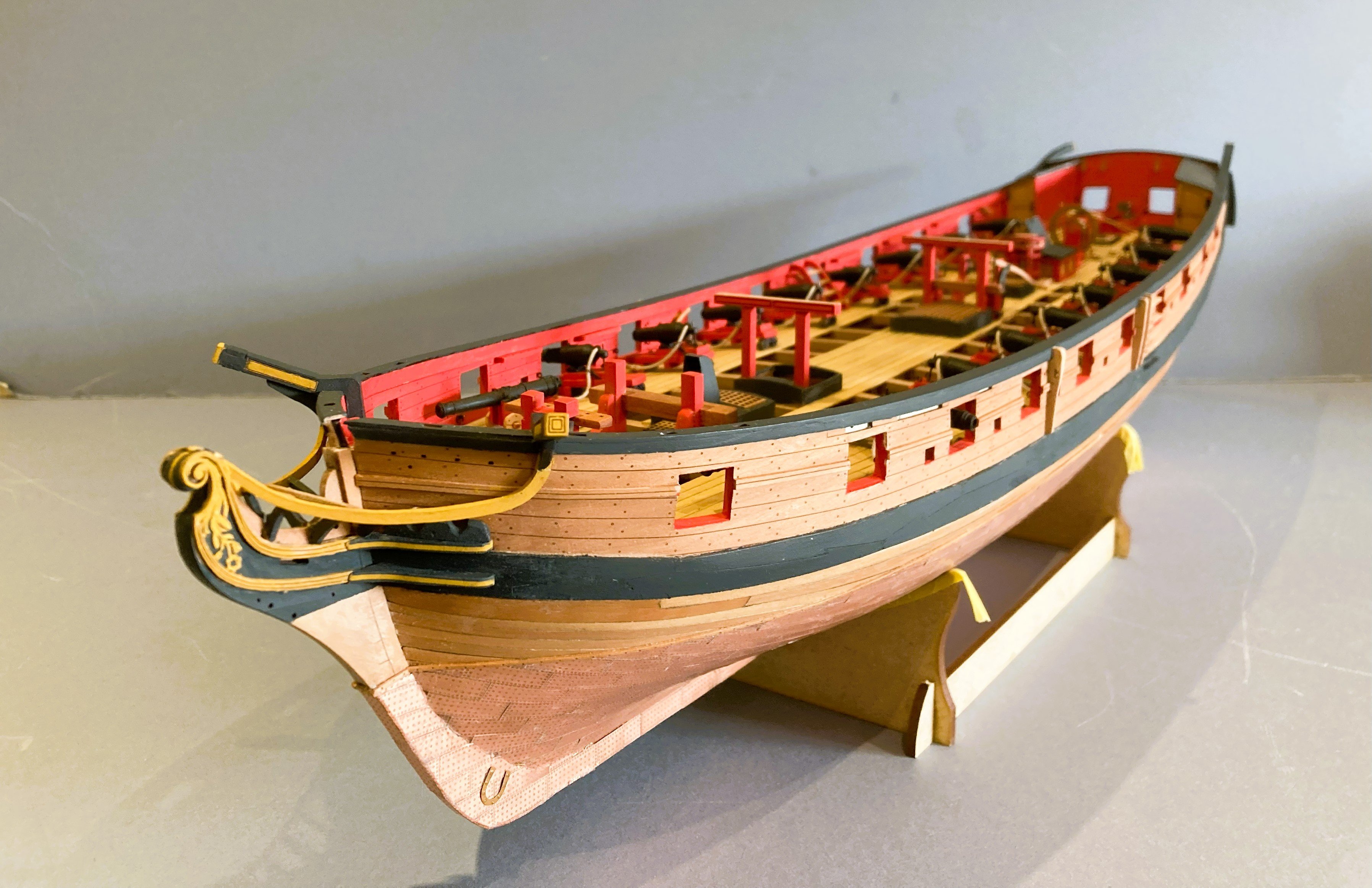
 Post 79 18’ Cutter I had already painted the interior hull and applied a coat of Vallejo Black/Grey to the outer hull. This small cutter will be suspended from the stern davits, which will provide interest and add the opportunity to add tackles to the davits. Unlike the 22’ cutter the footwaling is incorporated in the resin moulding. 4297sc Works very well at this scale. The inboard fittings are cut from 0.6mm Pear and are therefore very delicate. 4408a The gratings are beautifully cut but won’t stand even the lightest pressure without risk of breakage. I did find it necessary to add a strip beneath the fore grating which was showing signs of splitting as I teased it into position. I also added a lateral support beneath the sternsheet thwart. Even so, these fittings are streets ahead of the previous versions in brass etch. 4409a The sternsheets are another snap risk area. To fit these I found it helped to slightly flex the hull outwards whilst softly easing the sheets into place, so the notches aligned with the frames. 4420b The Bow thwarts present another issue of getting a close formation to the round of the hull. I found it easier to remove the fore side pieces and fit the thwart first. As with the larger cutter I added the Mast clamp and rudder hanging details, altho’ the rudder won’t be in place with the boat on the stern davits. 4446 Fitting the pintles and gudgeons was quite tricky as very tiny eyelets and pins are required, the process not helped by fat fingers and dodgy eyes. The oars for the cutter are of the style I would expect to see, so it is a puzzlement why the oars for the larger cutter, that I replaced, differed in style. 4414a In a raw state here. A slight round is required on the shafts and the blades require thinning down. 4431a 4436a 4457a 4458a 4460a 4461a 4465a I very much like these Resin boats, and altho’ we are saved the the effort of planking tiny hulls there is still a lot of work to do to get a good finish. I think the all-wood versions still have a place for those who like the challenge, and satisfaction is certainly to be had from successfully completing one of these mini projects. B.E. 25/05/2025


- 332 replies
-
- 22
-

-

-
- Harpy
- Vanguard Models
- (and 1 more)
-
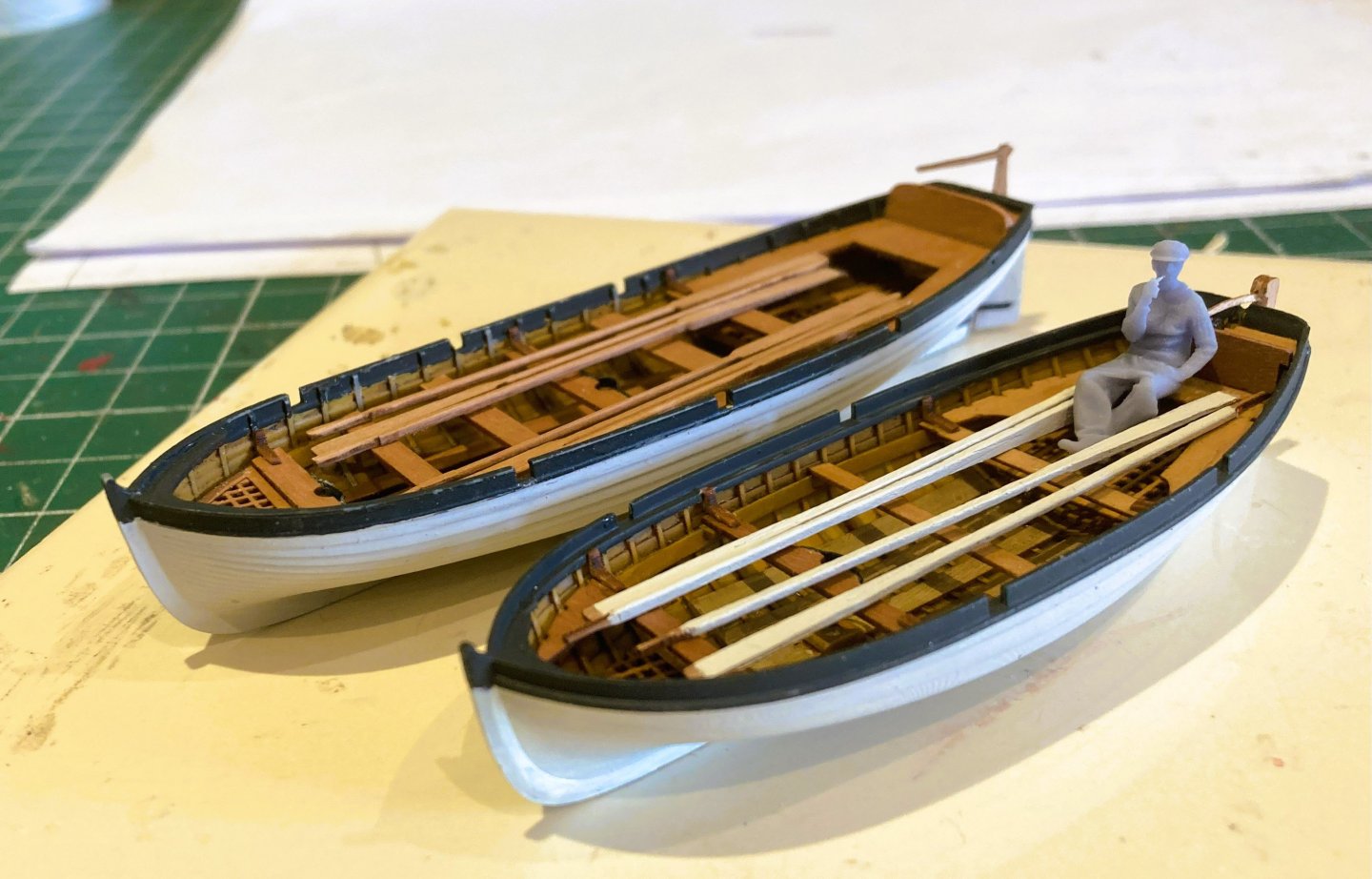
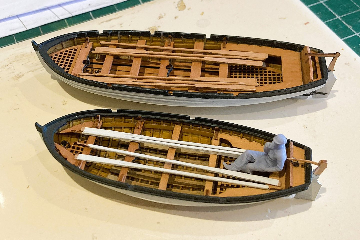
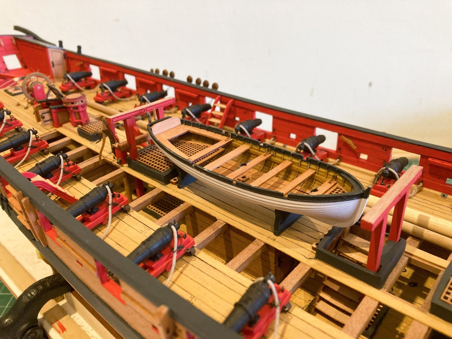
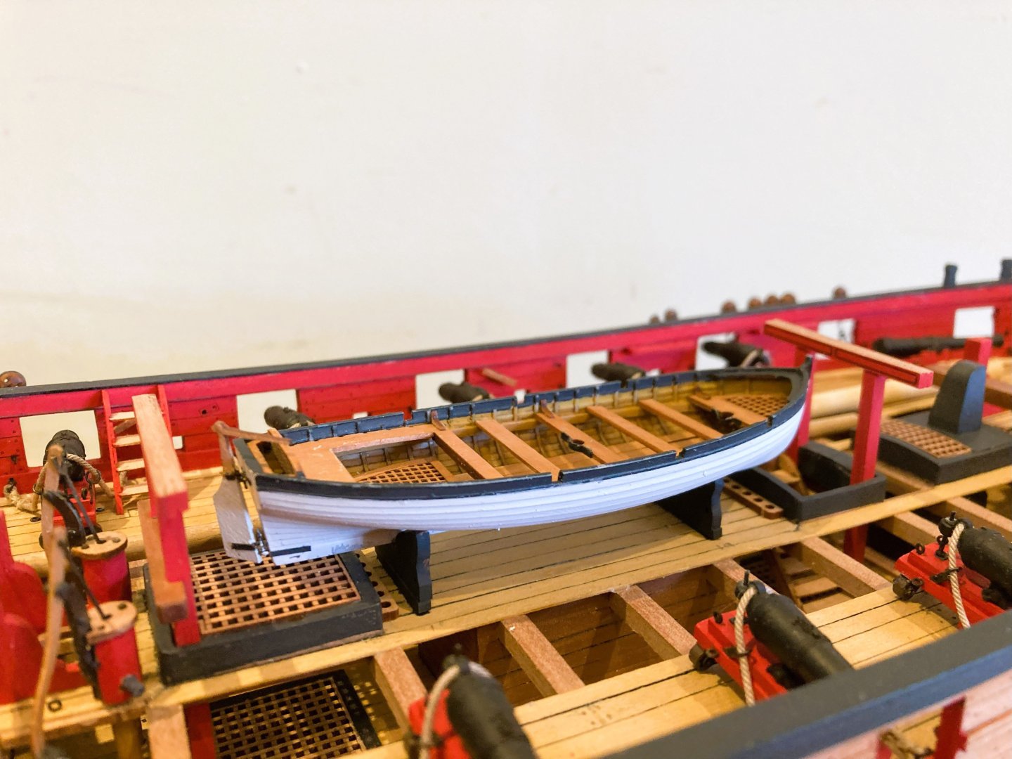
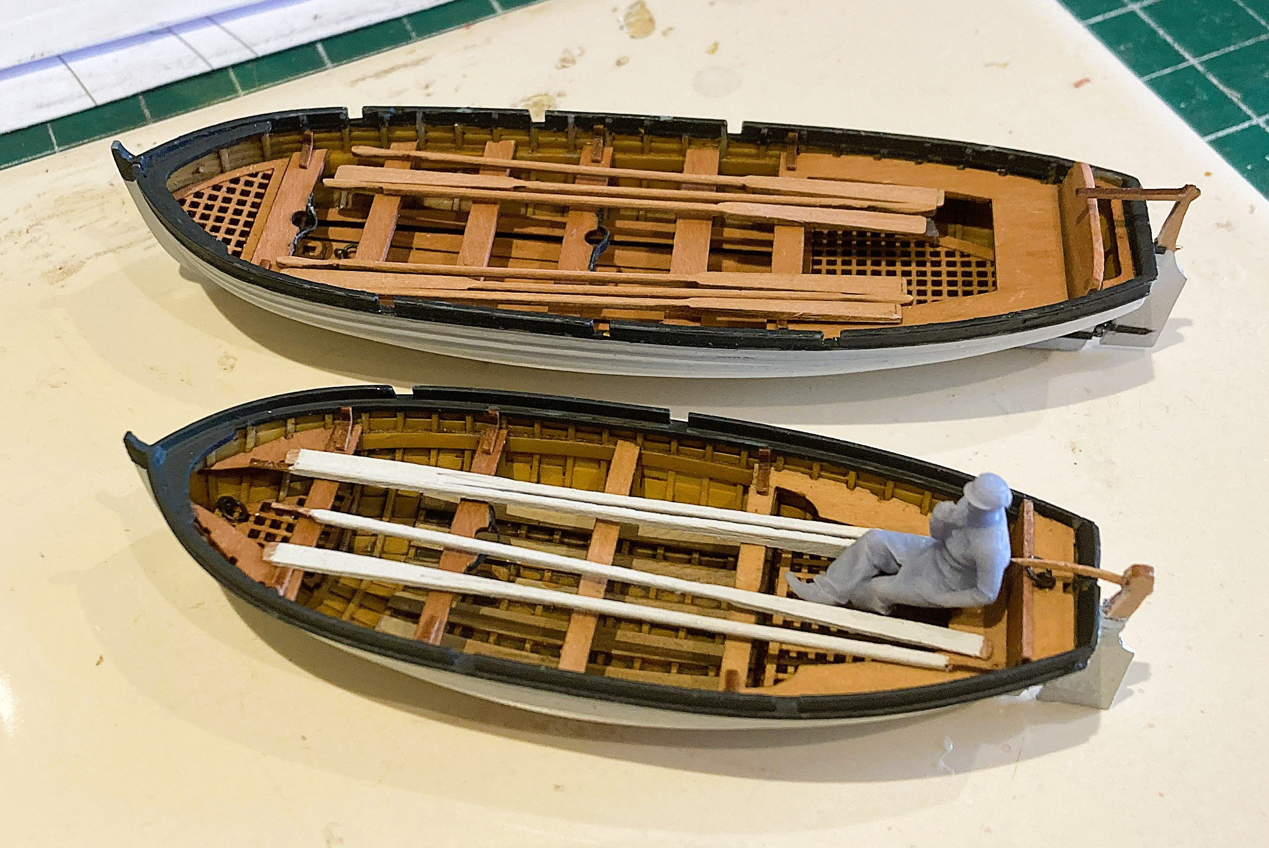
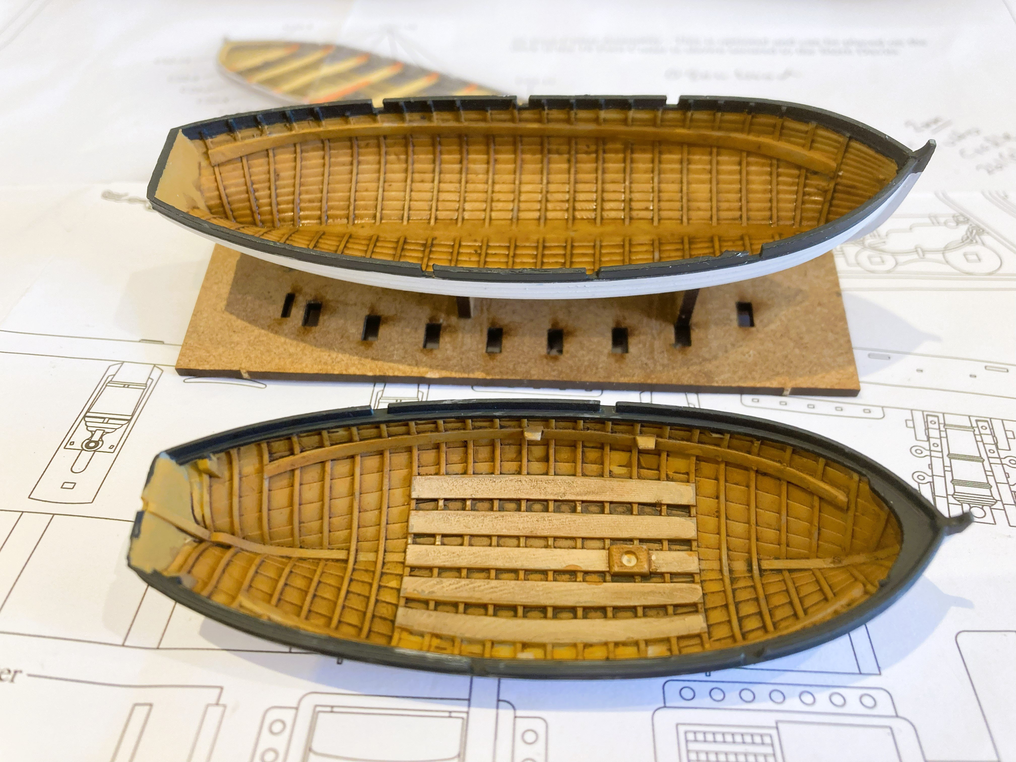
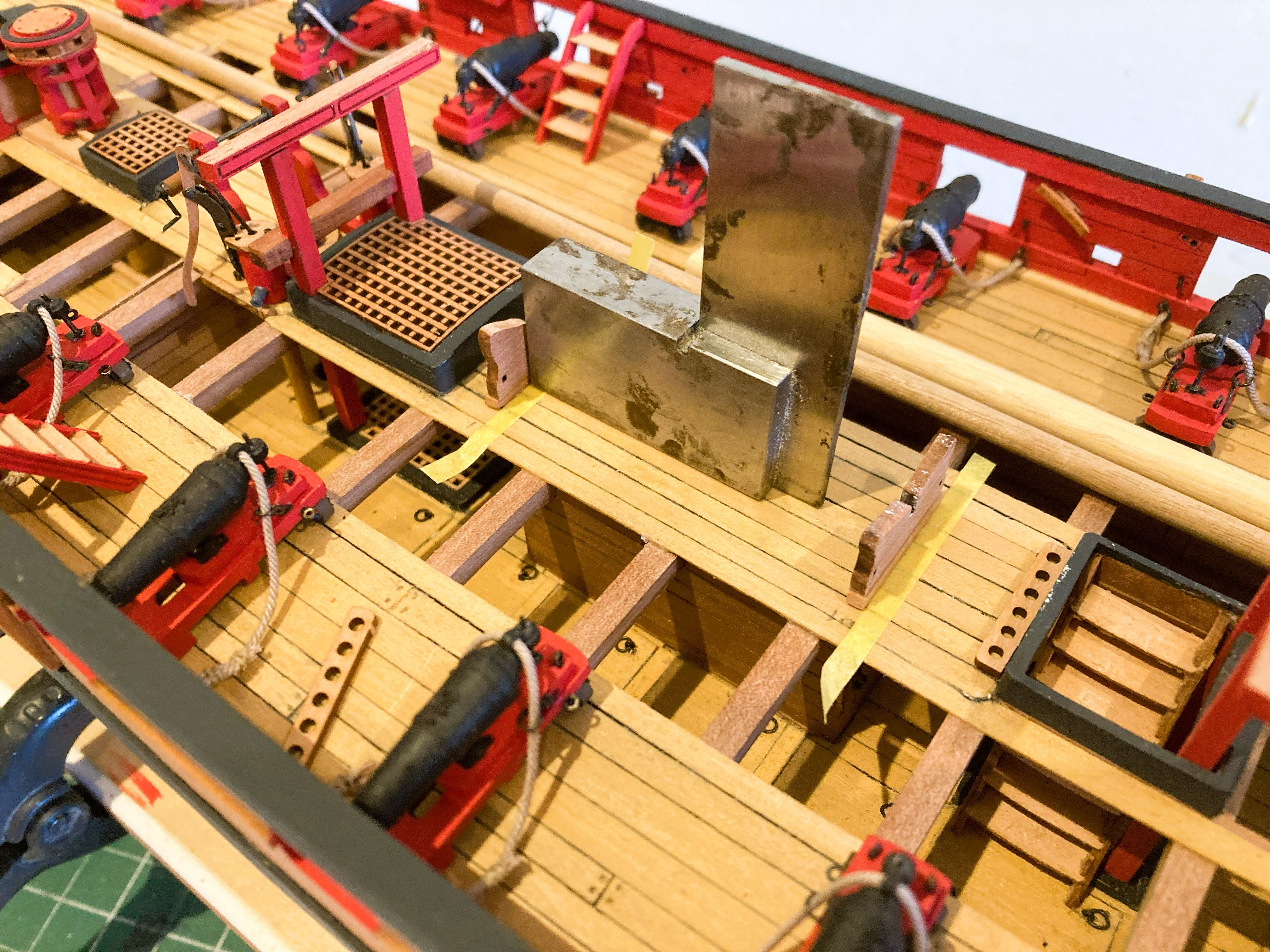
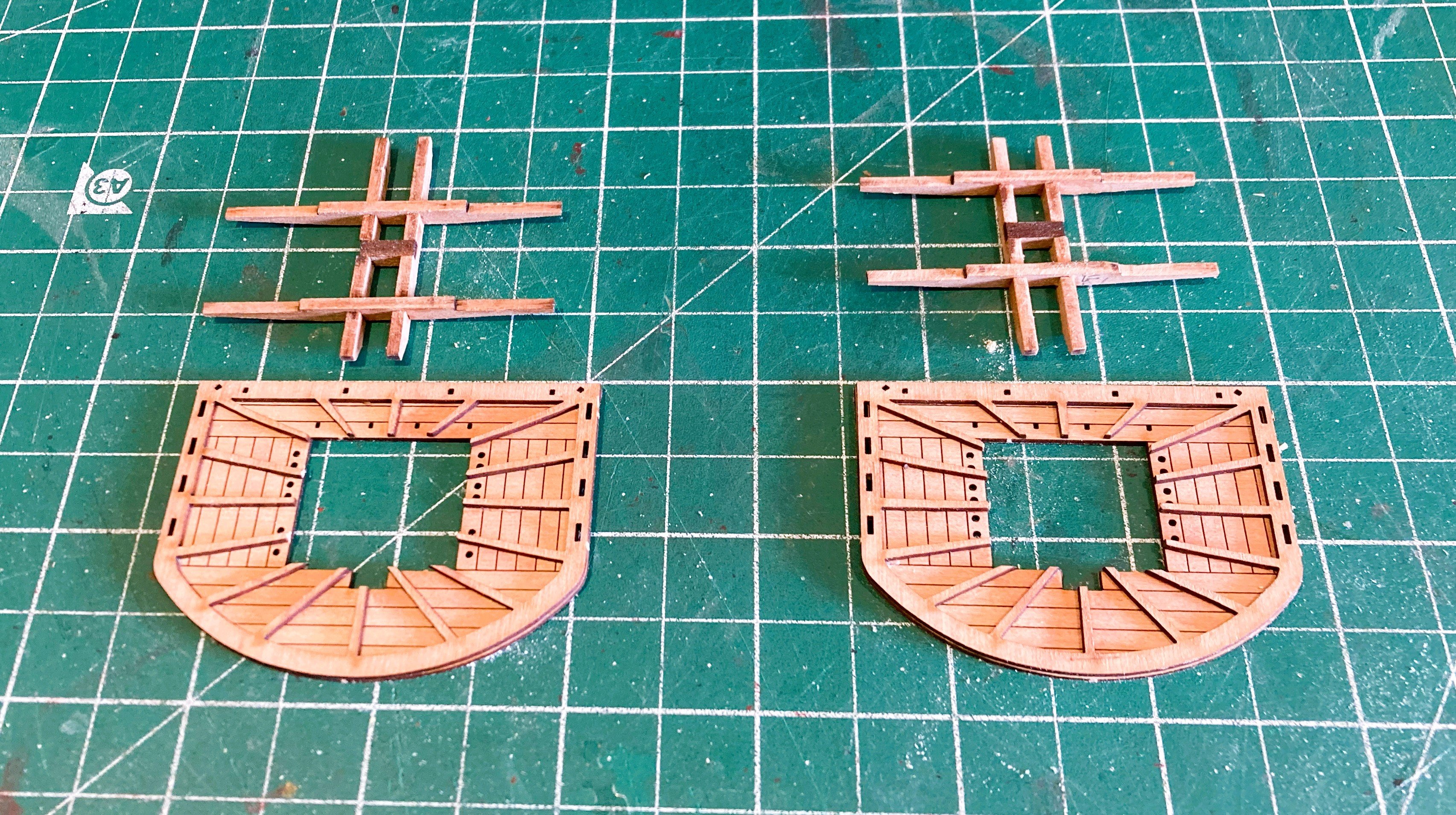
Post 78 Cutters 18’ and 22’ These are the new resin hulled version with Pearwood fittings. Nicely formed with Lapstrake planking, detailed framing, mast steps, and rowlocks set-up for single banked rowing. The colour scheme needs to be decided first, something that co-ordinates with the main ship scheme. For the outer hull colour I used Vallejo White/grey, and for the Gunwales Black/grey. I think this gives a more scale effect. For the inner hull I used a combination of oche brown shade mixtures until I got a look I liked. I then applied a wash of Dark Brown. 4297a This picked up the inner Lapstrake planking. I applied the same scheme to both cutters. The Pearwood fittings I left bright just treated with w-o-p. 22’ Cutter Inserting the Pearwood fittings, takes a little care, they are quite delicate, particularly the stern sheets. They are accurately cut to fit around the hull ribs but light pressure only should be used to fit into place. I used spots of cyano. 4308a One thing I did note ; there does not seem to be a laser cut thwart for the aftermost position. A minor issue as one is easily cut from the laser fret. Adding detail Adding the mast clamps to the thwarts is a small improvement, easily done using black card. 4301a Using a stick helps align the thwart with the mast step. 4309a I also like to add lifting rings to the keelson. 4317a At this scale it is feasible to add the rudder hanging ironware to the Cutter stern. This comprises a long pintle, and Gudgeon ring. Fiddly, but it’s stuff I like to do. 4316a This particular arrangement is designed for quick attachment/ removal of the rudder. The set-up for rowing is three pairs of offset rowlocks which would suggest single banked rowing positions. The oar lengths would suggest double banked rowing, so with this arrangement there would presumably be one rower per thwart, alternating port and starboard. I’m not too keen on the provided oars for the 22’ cutter, the blade looks too short and paddle like for my taste. 4305a The oar style supplied with Indy looks more the shape to my eye and fortunately I had some spares I could utilise. Boat cradles are supplied (for the 18’ cutter) but will fit the 22’ cutter. If the larger cutter is to be stored on deck, the cradles need raising a little to allow the boat keel to clear the coamings. I added 2x2mm Pearwood strip to the bottom of the cradles. 4324a I always find fitting cradles a tricky exercise, getting them central to the deck, square, and correctly spaced to fit the hull. It would be easier to glue the hull to the cradles before fitting, but I prefer not to do that. 4325a 4327a 4328a Nice to see that my scale figure sits perfectly in the sternsheets. 4331a 4332a Some paintwork tidying is still required, but I’ll attend to that in conjunction with the 18’ Cutter B.E. 18/05/2025


- 332 replies
-
- 31
-
-
- Harpy
- Vanguard Models
- (and 1 more)
-
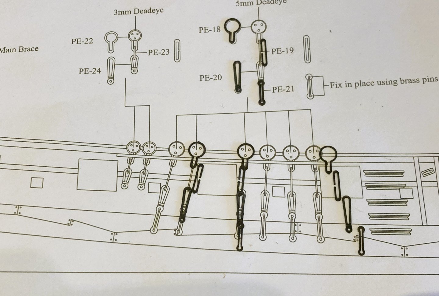
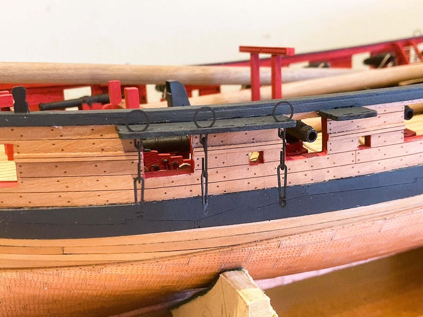
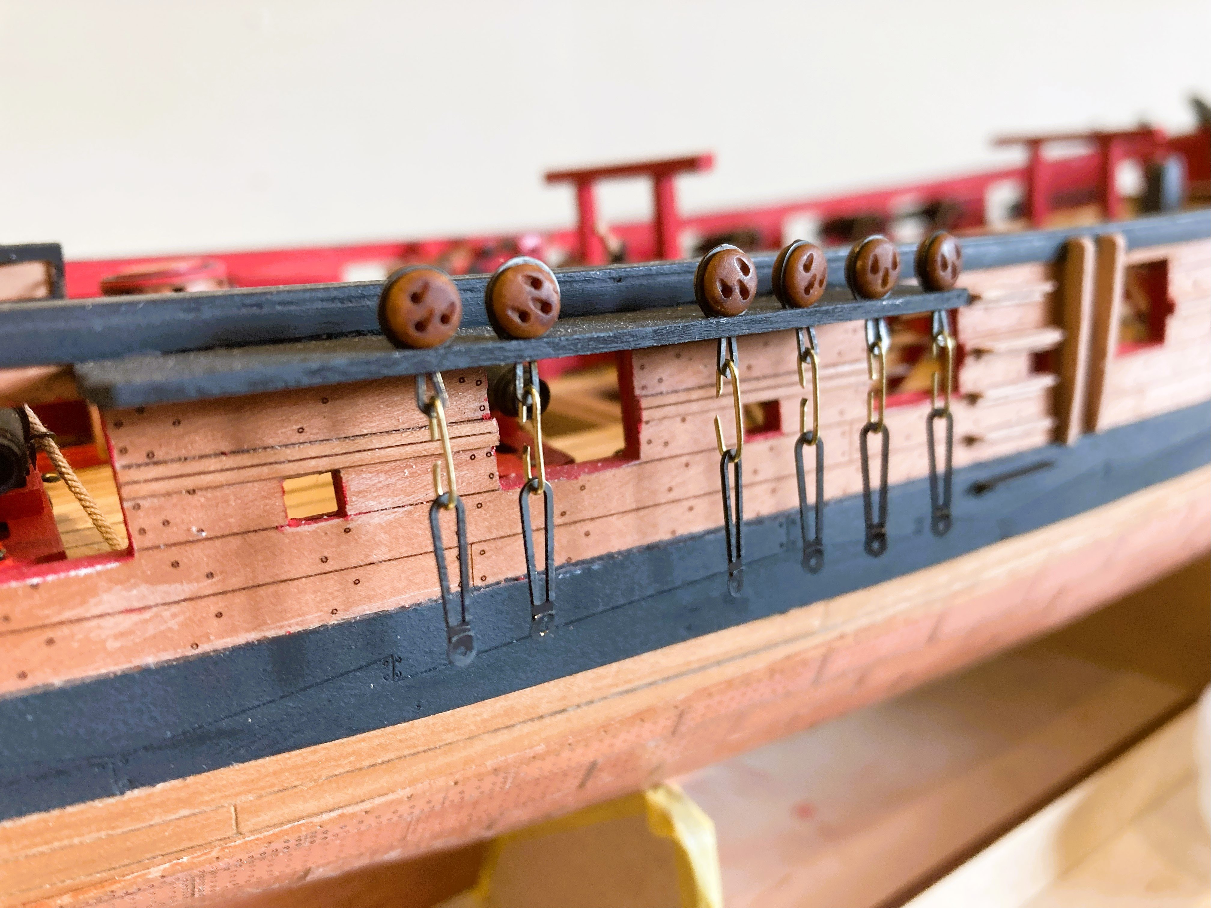
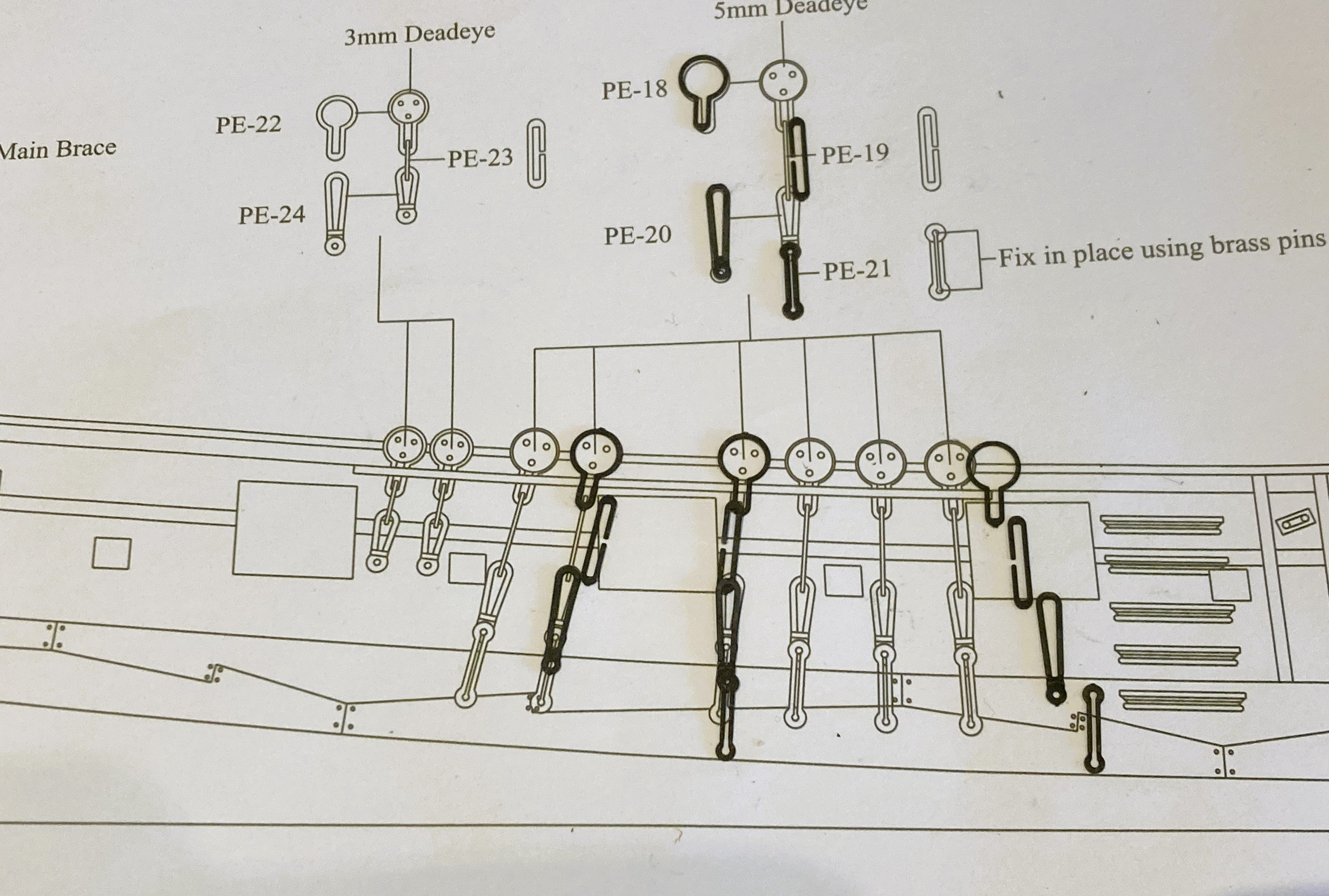
Post 77 Strops, chains, and plates. – Part three With new upper chain links made I can proceed with the fitting. 4266a Each one was trial fitted to check the drop before pinning to the hull. 4265a A tiresome business but the end result at least complies with the Adm./kit plans, rather than the less convincing look that would follow had I used all the provided parts as is. Topmast and T’gallant Backstays I won’t be rigging these but the channel deadeyes will be in place. The kit uses 5mm ø deadeyes for the lower shrouds and 3mm deadeyes for the Topmast and T’gallant backstays. Steel indicates a thimble set-up for the T’gallant Backstays but the ADm plan shows deadeyes in place. 4272a I have opted to use 4mm deadeyes for the Topmasts, and 3mm for the T’gallants. Although not exactly to scale this reflects the reduction in size of the upper masts rigging line. 4271a As with the shrouds I has to re-make the upper chain link to bring the lower link to the correct level. These are tiny links which took a few attempts to get right, or replace those that just on completion pinged off into the ether. An exercise in frustration. 4273a 4274a 4275a 4277a I think a glass of Merlot is required before I tackle the Port side. Cheers,🍷 B.E. 12/05/2025


- 332 replies
-
- 19
-
-
- Harpy
- Vanguard Models
- (and 1 more)
-
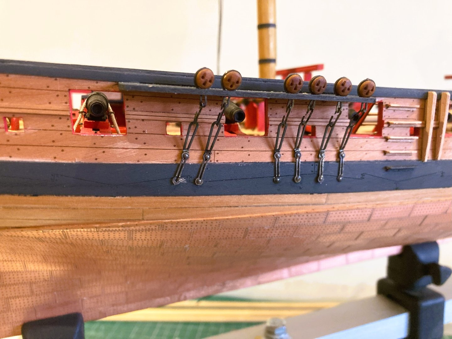
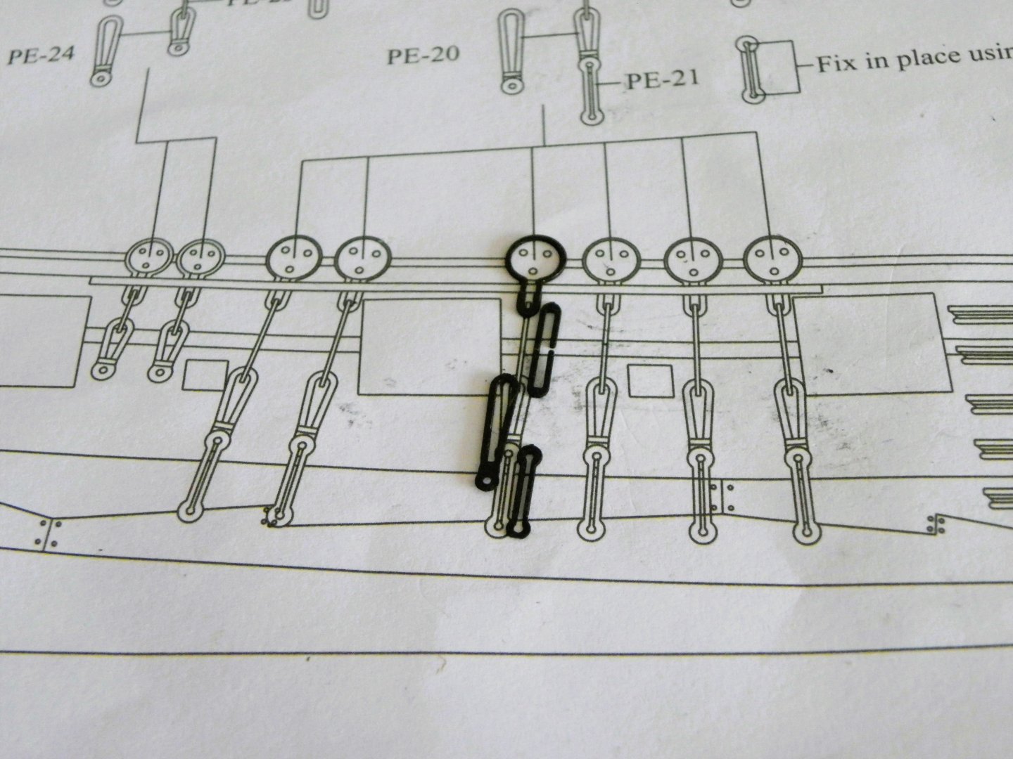
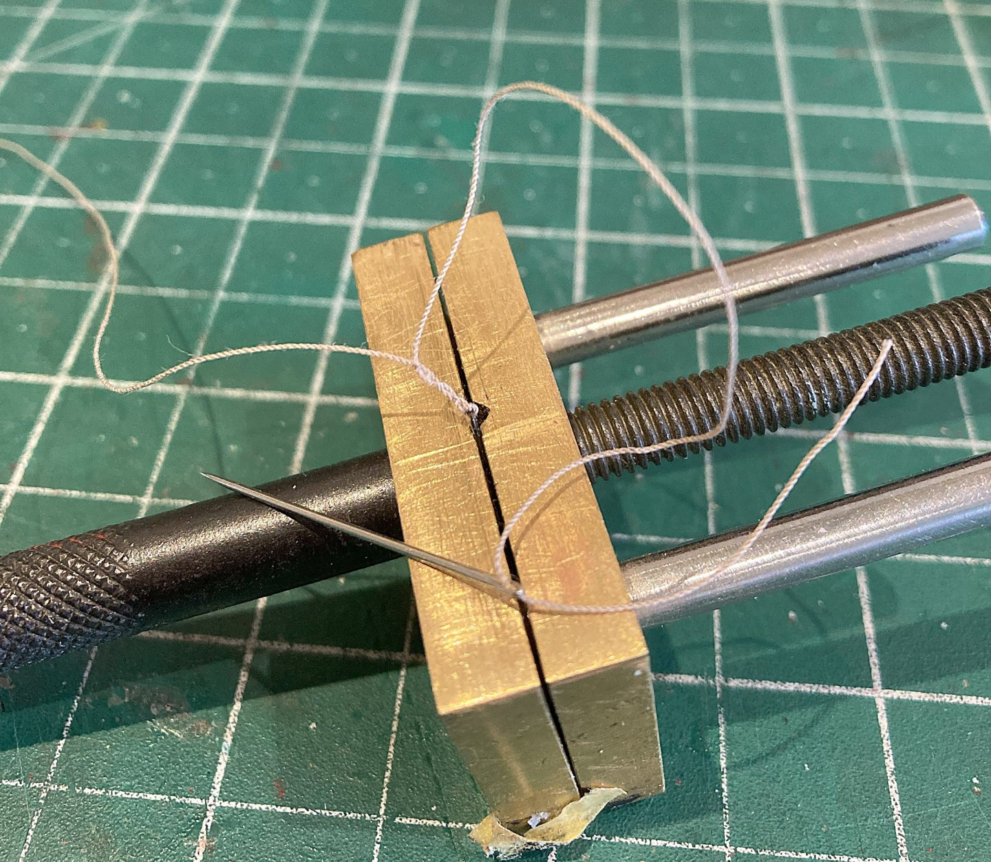
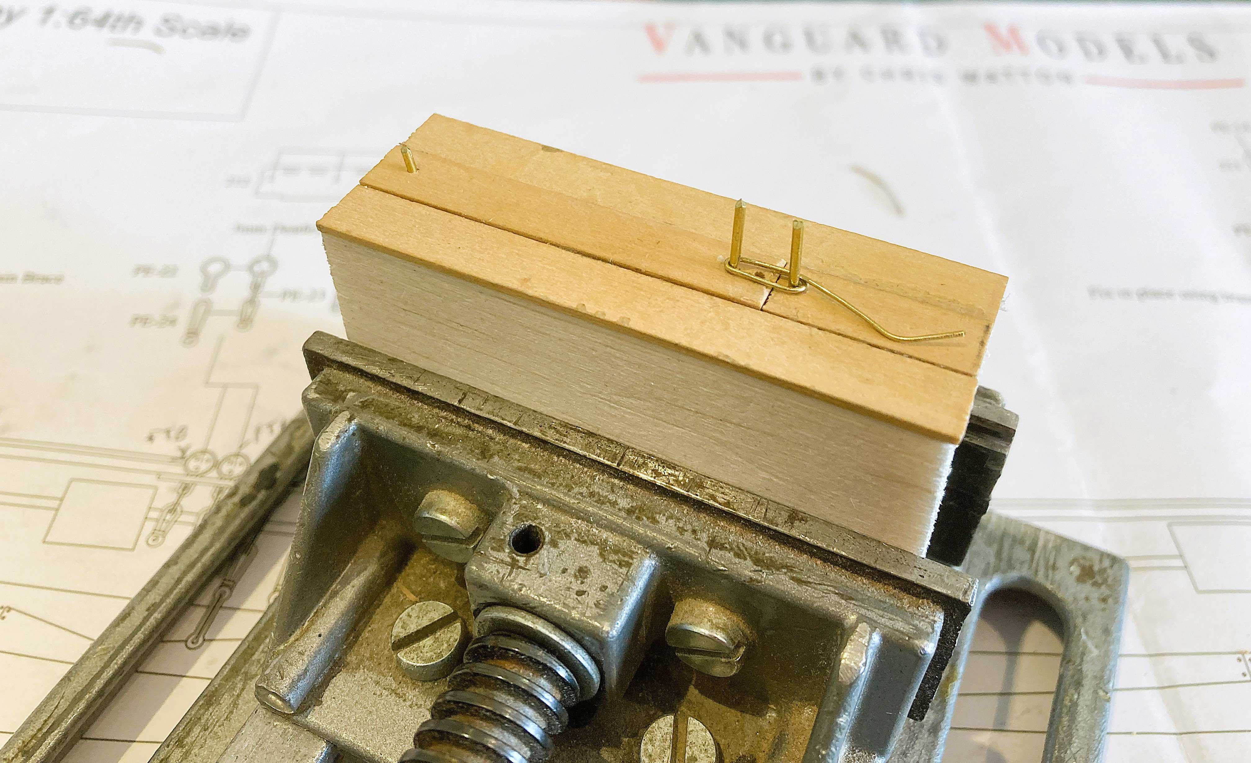
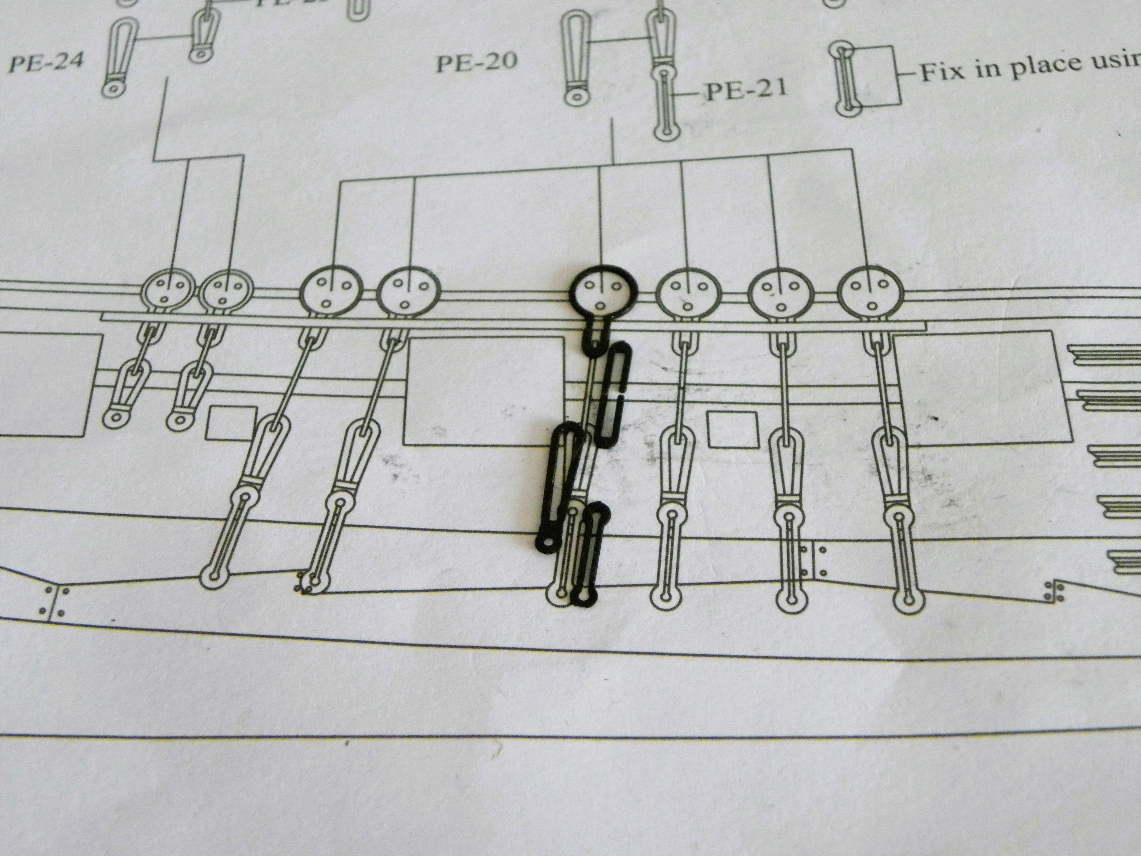
Post 76 Strops, chains, and plates. – Part two 004 As I noted in Post 73, if I use the deadeye sets as issued the Preventer plates are thrown too far down on the Wale. They should be as per the plan as above. 4226a I have completed the lower mast Deadeye strop fixing using the replacement Resin Deadeyes. Stropping the Deadeyes does inevitably mar the blackening of the strops, but a test of the resin deadeye in the blackening fluid has no adverse effect. Once fitted the combination is re- dipped in the blackening. The usual approach would be to make up the sets on the model, Upper link attached to the Deadeye strop, followed by the Lower link, thro’ which the Preventer plate would be pinned. The lower fixing of the Preventer plate should sit around half way down the wale, with the lower chain link sitting just above the wale top. I found this is not the case, so a tricky job ensues, one that I don’t particularly relish. My approach will be to use Brass wire (0.5mm ø) to represent the upper chain link. It would prove difficult to modify the kit link because of thicker sections at the top and bottom. 4237a I first need to make a jig to form the links. There is an excellent ‘how to’ in Volume 11 of The ffm BY David Antscherl. 4238a In reality the lengths of the upper links vary to accommodate the increasing angles of the aftermost shrouds. The jig allows the size to be adjusted as required, altho’ on Harpy the effect is minimal. 4242a Strictly speaking the links should be closed but without open slots along the Channel fronts to insert completed strop and chain units, it becomes tricky. 0017 This test link shows the correct position of the Preventer Plate. 4253a The link at 8mm in length is 3mm less than the provided kit link. With the masts in place I firstly need to mark the line of the shrouds. The kit shrouds are of 1mm ø black line, but I will be using 0.88mm ø Syren rigging line, which is spot on for scale for the lower shrouds. I find provided black kit line too stark for my taste and my approach is to use natural line dyed with Dark Jacobean oak wood stain to represent the standing rigging. 4249a Kit line used to mark the positions of the lower Preventer Plate bolt. I think I can now proceed. B.E. 10/05/2025


- 332 replies
-
- 16
-
-
- Harpy
- Vanguard Models
- (and 1 more)
-
Sound advice Chris, the only thing ca is of use for in rigging is forming needle points on lines to assist feeding thro' sheave holes, and sealing the cut ends of polyester line. Cheers, B.E.
- 332 replies
-
- 6
-
-
- Harpy
- Vanguard Models
- (and 1 more)
-
Thank you Greg, My thought is to rig her without yards, and with the Topmasts in the lowered position. I will have to make the Topmasts from square stock with the heel sheaves in place. Alternatively I could store the Topmasts on the Gallows. This is all about space saving. I do prefer to build up the mast sections on the model rather than glue all the sections together before fitting, and I tend to glue as little as possible on my models including the masts. Depending on the mast fit I sometimes apply the merest spot of pva, sufficient to hold the mast square, but with the bond easily broken with a twist. I’m always thinking I may want to remove this one day. Regards, B.E.
- 332 replies
-
- 4
-
-
- Harpy
- Vanguard Models
- (and 1 more)
-
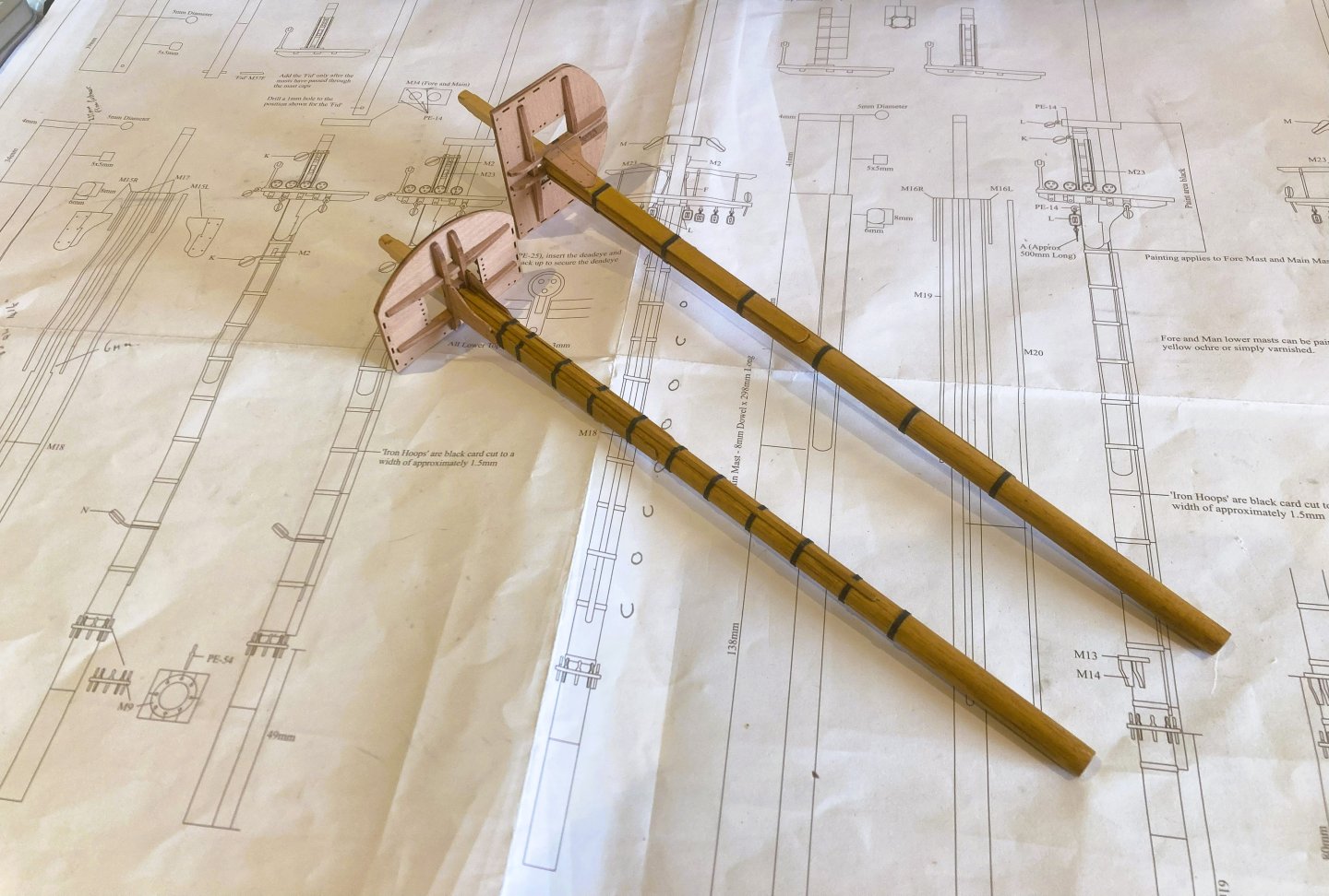
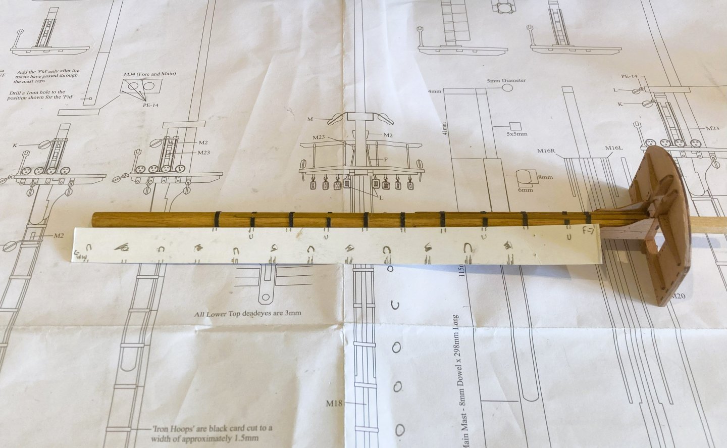
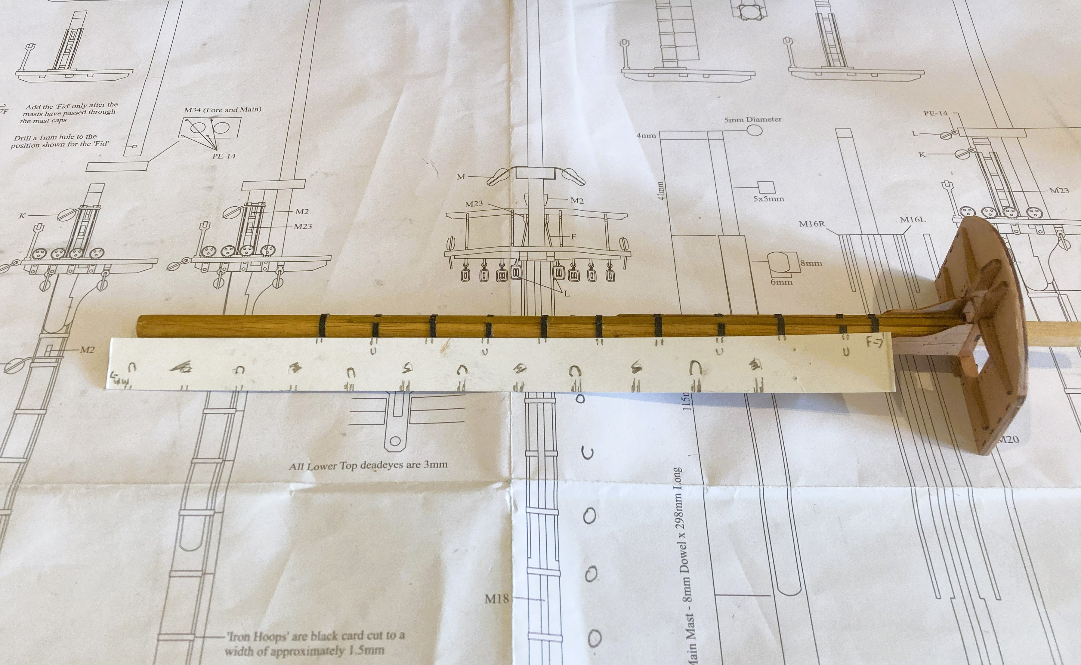
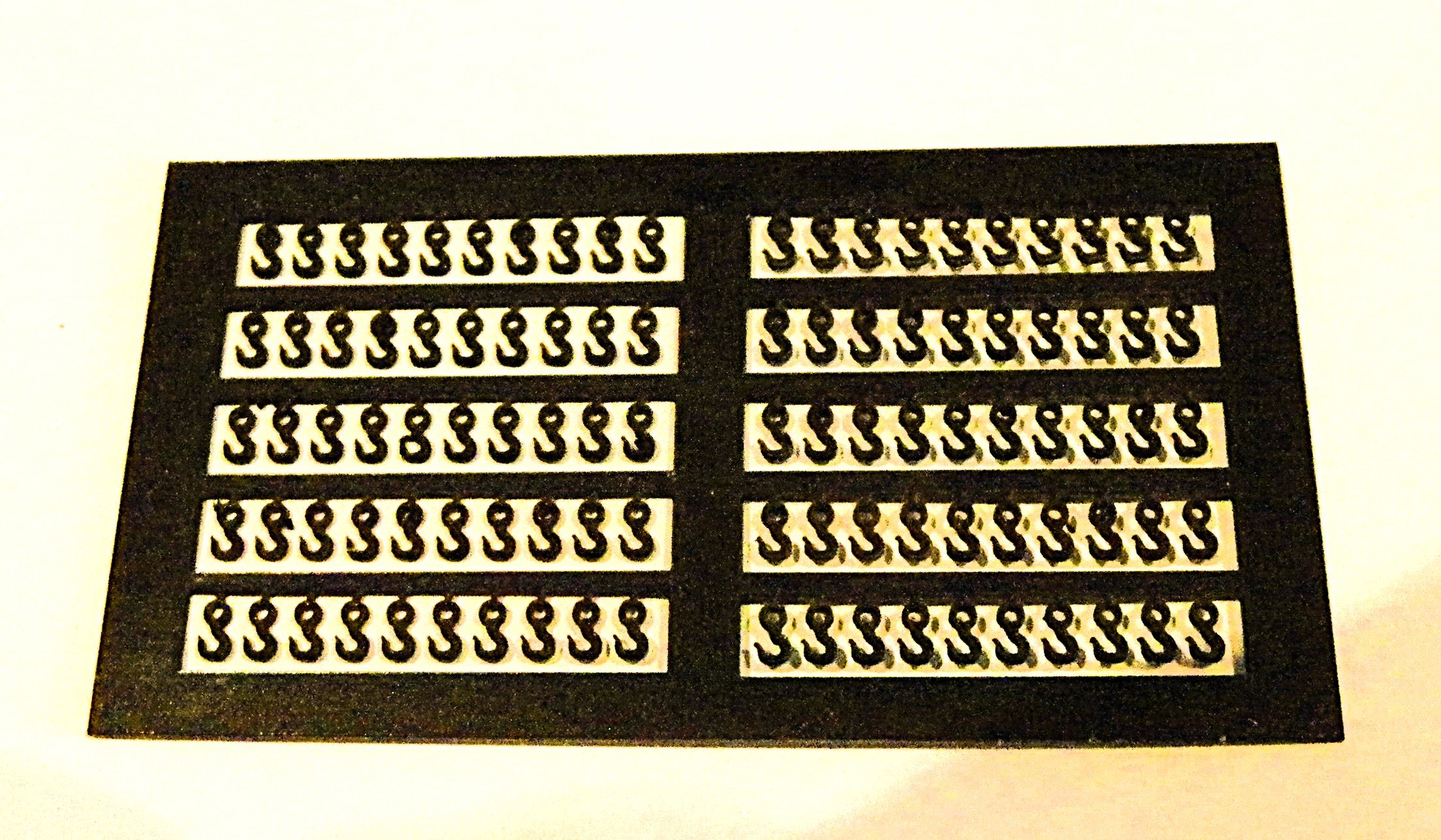
Post 75 Masts (Part 2) Mast Hoops There are twelve iron hoops supporting the Main mast, alternating between under and over the Front Fish. The Foremast has ten hoops but they don’t uniformly alternate, six sit above the front fish and four beneath. There are no wooldings involved with the Harpy build. The kit provides black card for the purpose of Hoop making and a scale breadth of 1.5mm is indicated. This agrees with the sizes given by Steel. Breadth – 4” - 4½” breadth, ½” - ⅝” thick. Whilst I often use slices of heat shrink tubing for hoops I will be using the card option which will better conform to the profile around cheeks and Fish. 4203a I fit the hoops that fit beneath the Fish first, here on the Fore mast. 4208a I use a template to mark the hoop positions down the mast. 4207a Fitting the hoops is a bit fiddly, care has to be taken to remove any glue spread onto the mast. 4213a 4214a 4215a 4216a I have left the hoops black as a contrast but in reality they would probably have been painted along with the masts by the early 19thcentury. Bolsters These are provided as short sections of 2x2mm square stock. In my view they are a tad on the short side as a means of protecting the shrouds, particularly if the shrouds are to be properly served. 4221a I replaced the kit parts with quarter rounded 2x2.5mm stuff. This also overhangs the trestletrees by a fraction as it should. I’m leaving the masts for a while as my supplies of Resin deadeyes have arrived and I’m keen to resolve the looming problem of over-long links, which has been on my mind since Post 73. B.E. 08/05/2025


- 332 replies
-
- 18
-
-
- Harpy
- Vanguard Models
- (and 1 more)
-
The innovation of Resin and 3d printing have been a game changer in ship modelling, a much higher level of accuracy and realism in fittings, particularly at smaller scales. Chris and Chuck have been prime leaders in this field and I'm a confirmed fan of their work. B.E.
- 332 replies
-
- 4
-
-
- Harpy
- Vanguard Models
- (and 1 more)
-
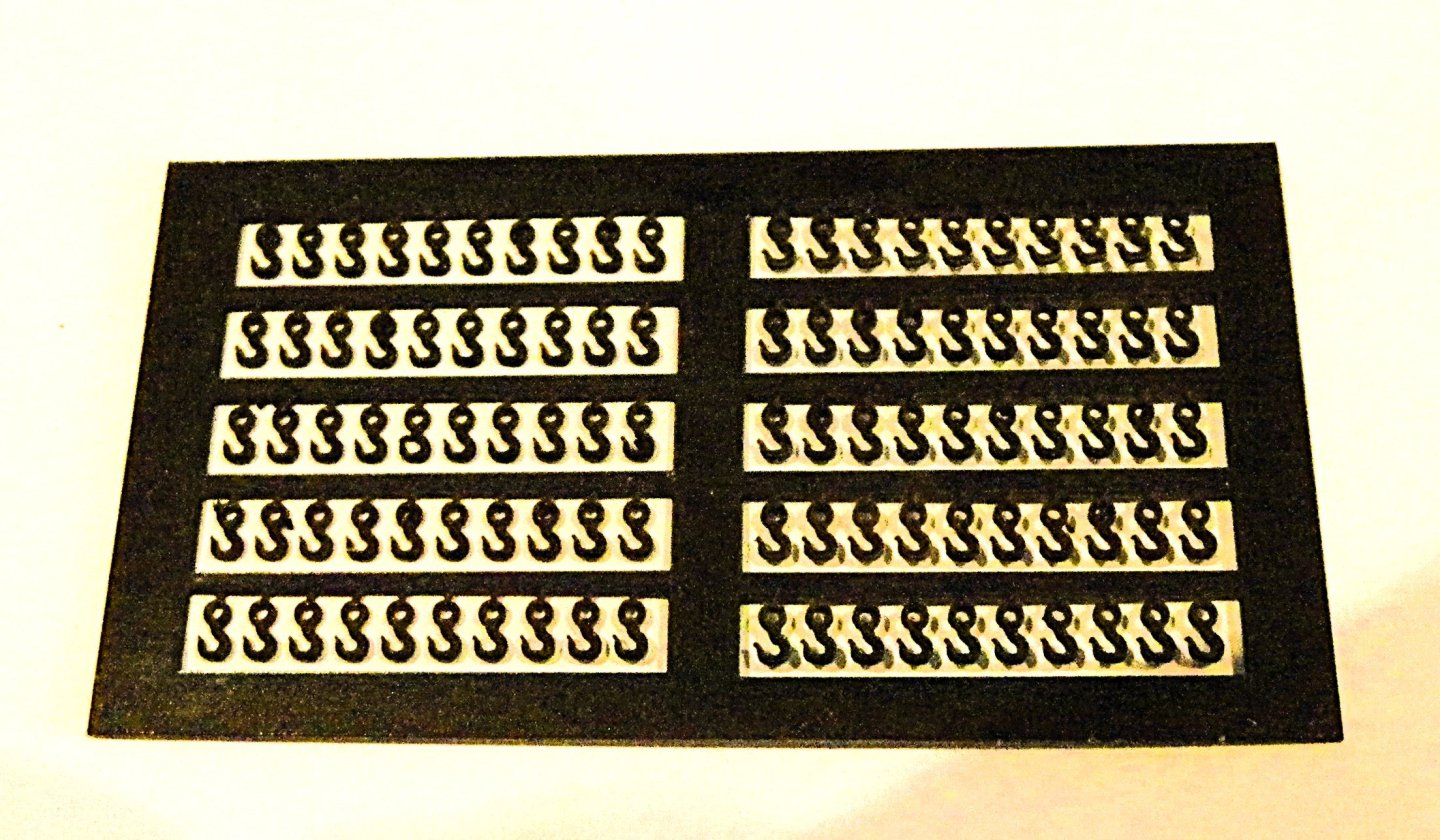
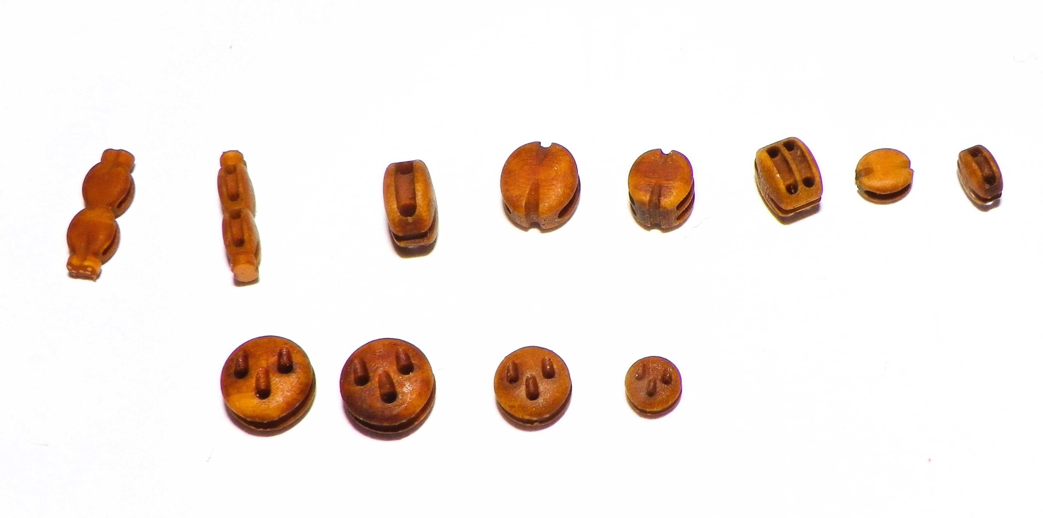
A pleasant surprise. My supply of resin deadeyes and blocks arrived today, a mere seven days from order to door. Thanks Chuck, excellent service. 0012 Swiss Pear Resin versions from Chuck’s Syren range. I am very pleased with these, the detail is way beyond the usual kit blocks. Note the shaping of the ‘eyes’ in the deadeyes, and the well formed sheaves and strop grooves in the blocks. 0014 3mm rigging hooks I also like these black plastic hooks, saves all that blackening of brass versions. I note that Chuck is contemplating making a 3/16” scale version of Resin Belay pins that should suit a 1:64 scale model. I do hope this comes to pass, they would be a nicer option than the rather two-dimensional brass etch versions. Back to the masts. B.E. 07/05/2025

- 332 replies
-
- 20
-
-
- Harpy
- Vanguard Models
- (and 1 more)
-
Well done Mark, she looks very impressive. a wonderful display model. B.E.
-
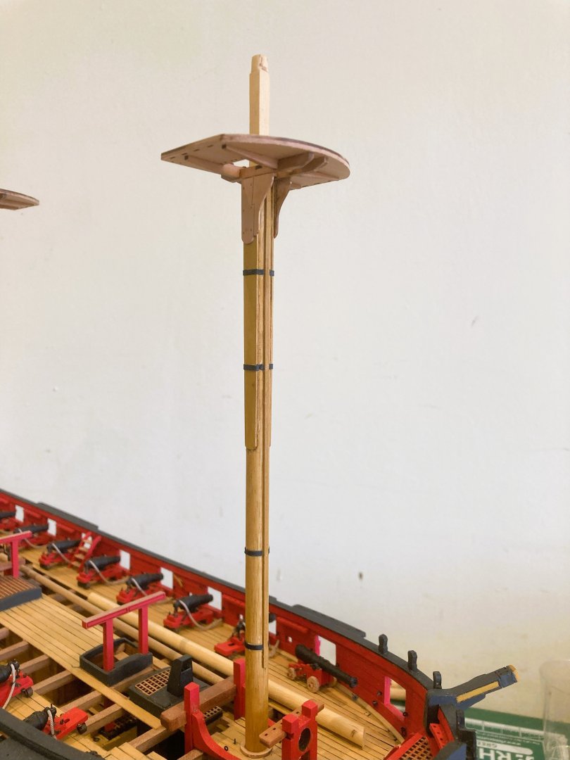
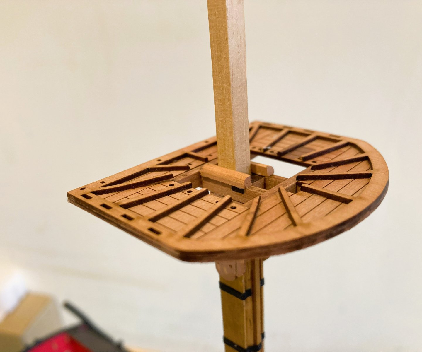
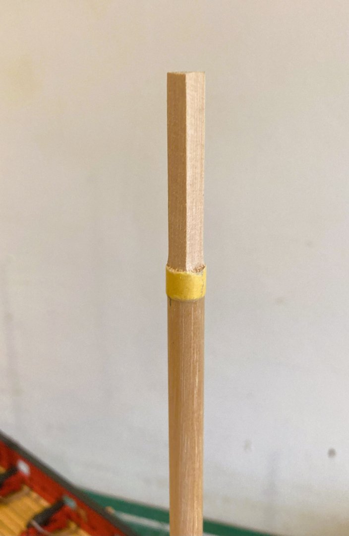
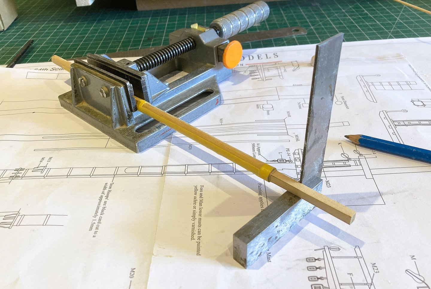
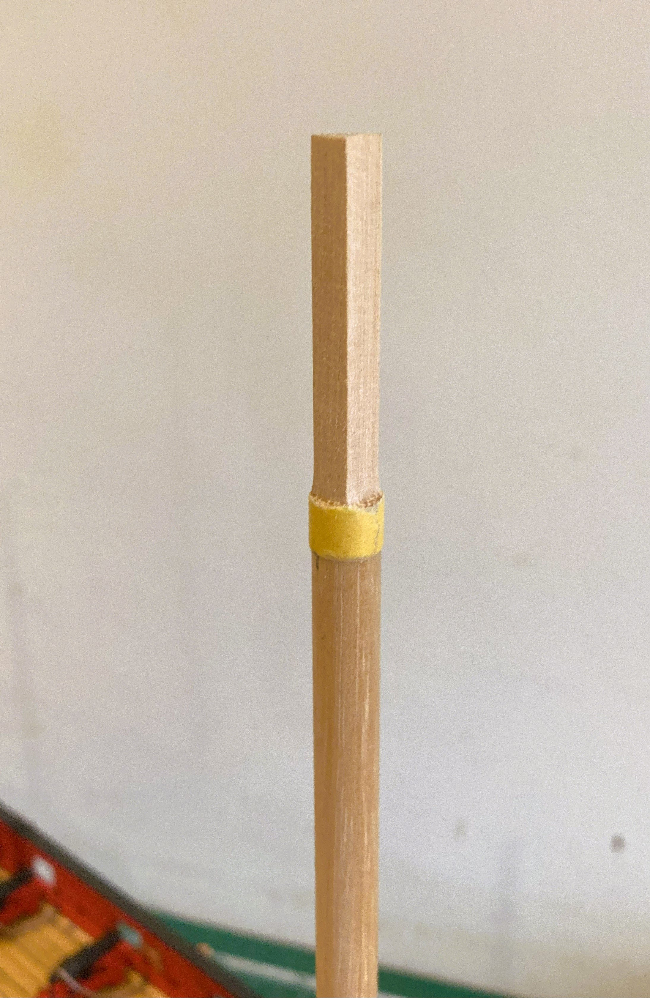
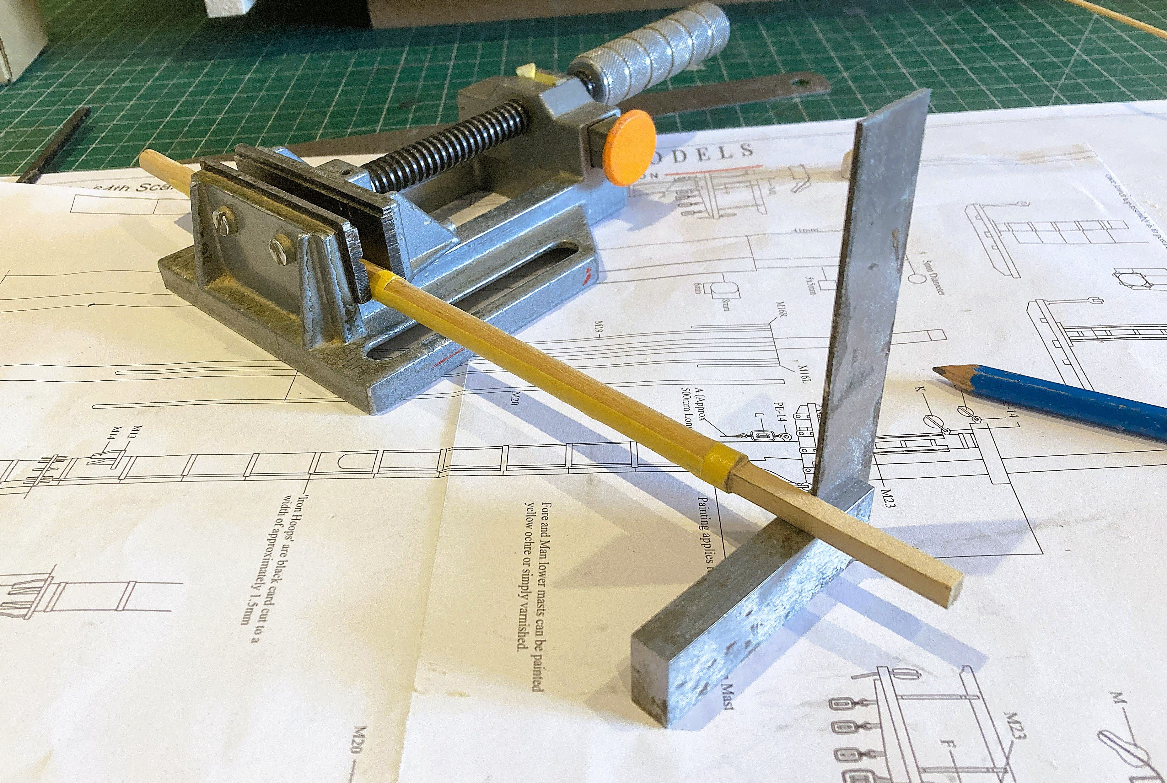
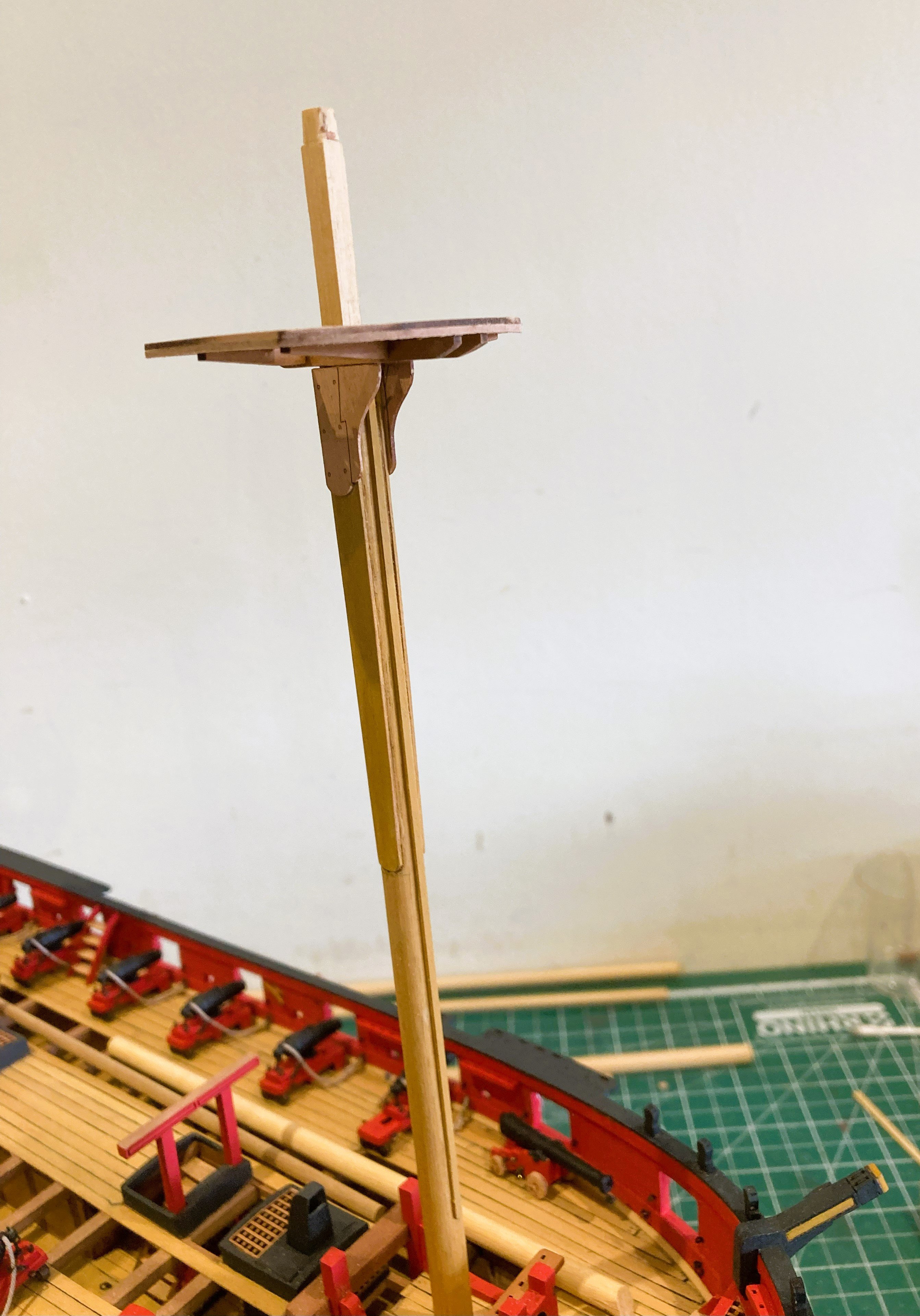
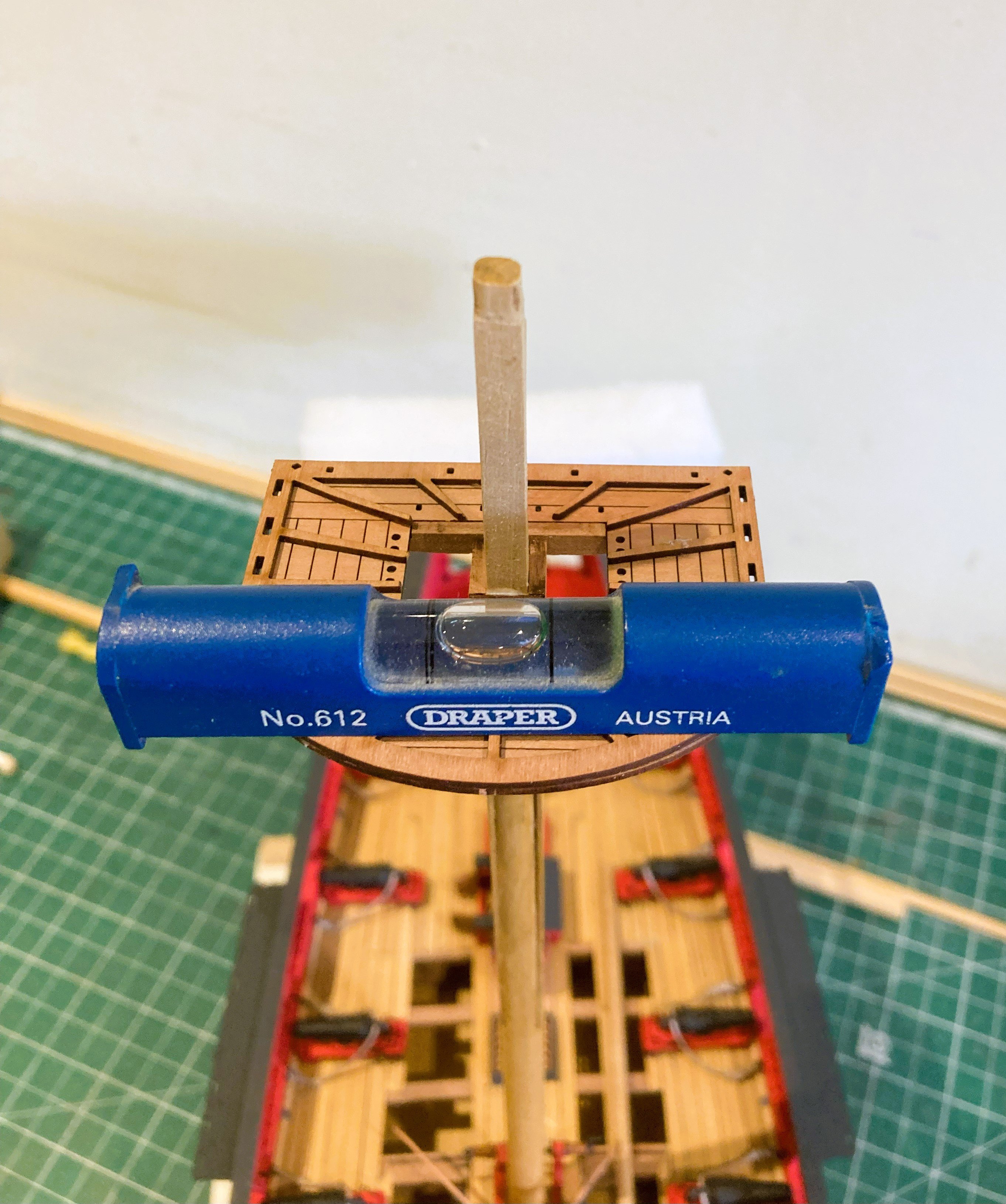
Fore and Main Masts. (Part 1) I am working these as per the kit dimensions using 8mm Ramin dowel. The trickiest part is forming the 5mm square mastheads from dowel. I do this by marking the square area on the dowel top, lining along for the required length, and filing using 120 grade sandpaper glued to a broad stick. I gauge by eye with constant measurement and square checks. 4138a I initially pare down to around 5.5mm before checking with the cross trees. It is then a case of reduction by degrees whilst maintaining the square profile. 4142a The sides of the stick are then sanded flat to accommodate the Cheeks. 4143a I use Tamiya tape to define the area to take the cheeks, again careful use of a broad sanding stick is all that is required with constant checking to ensure squareness. 4161a The masts were coated with w-o-p, and I painted the Pearwood cheeks to better tone with the Ramin Masts. I then use a water based oche tinted wood dye to even out the colour tone. The laser cut Trestle trees in Pearwood slot together cleanly and firmly. 4164a I very much like the Mast tops, beautifully cut and detailed, a joy to work with. Regardless of mast rake the tops should be level to the waterline. 4176a 4179a 4183a 4188a It seems to take me ages to ensure the Mast tops sit square and level, the final adjustments being made after gluing but before it sets. 4191a Once the mast tops are firmly fixed, the Bibs and Front fish are added. B.E. 06/05/2025


- 332 replies
-
- 23
-
-
- Harpy
- Vanguard Models
- (and 1 more)
-
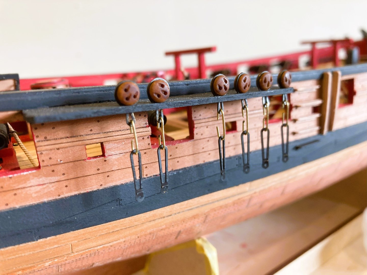
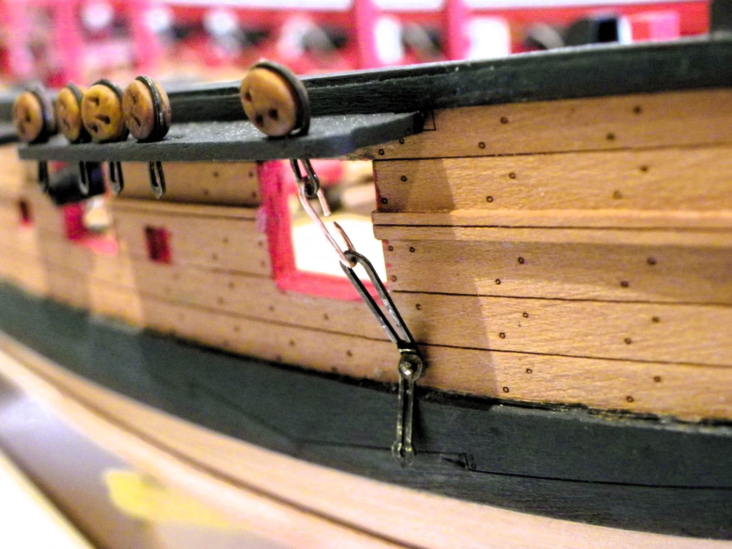
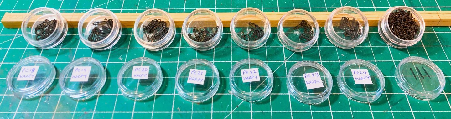
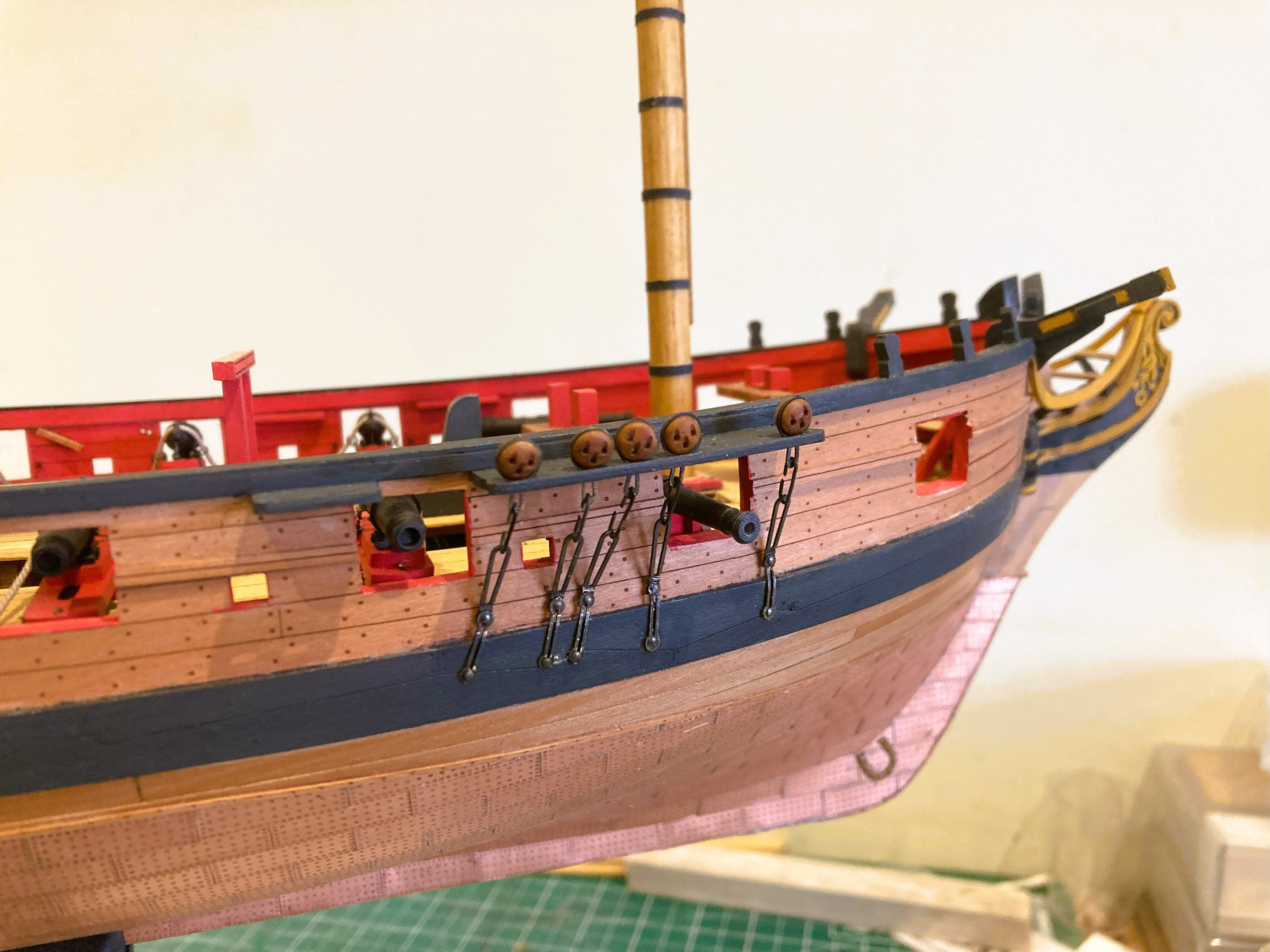
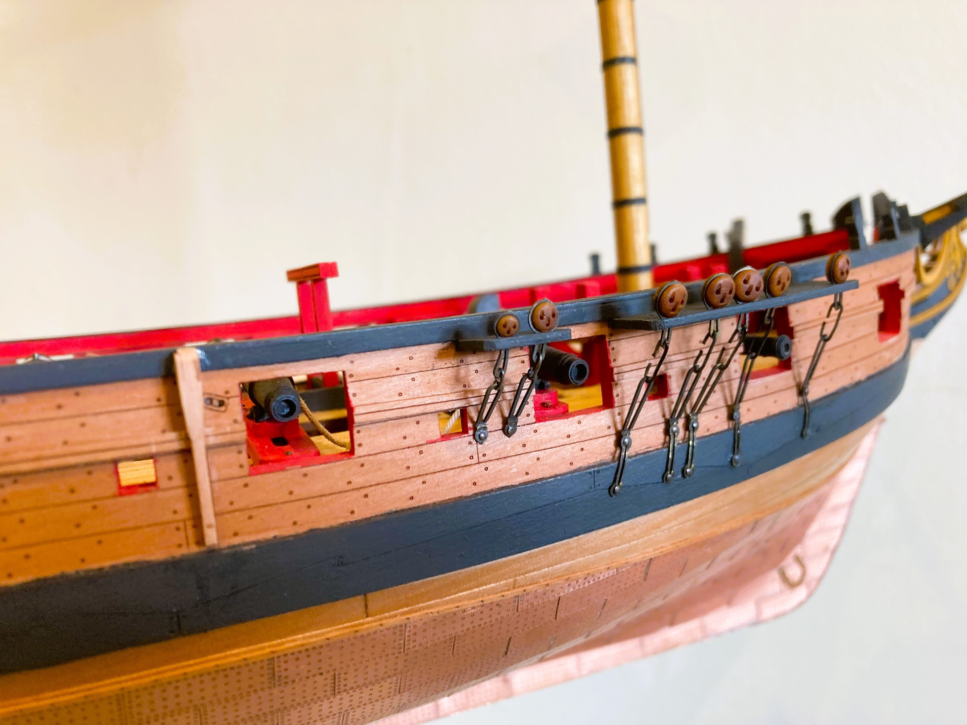
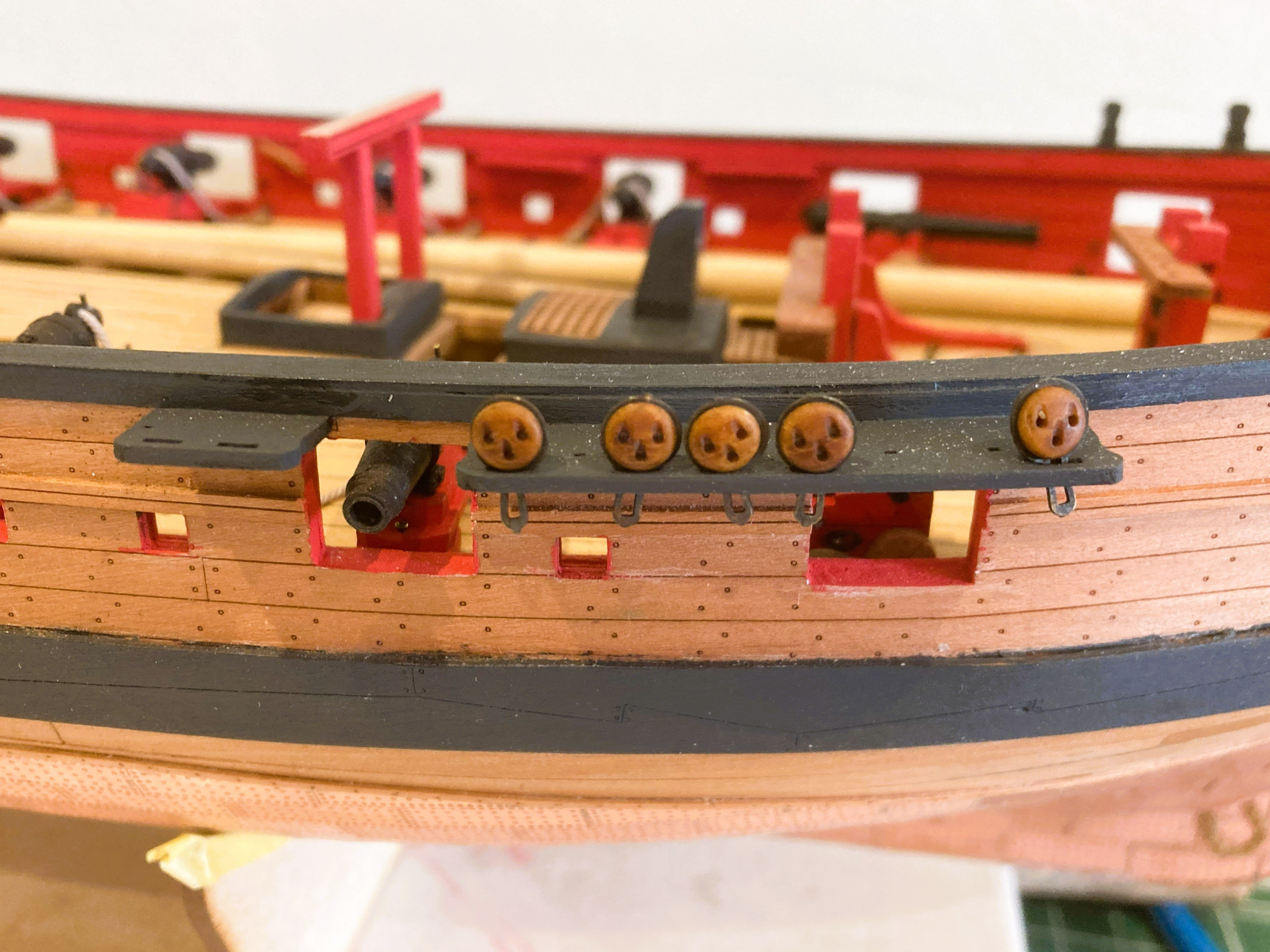
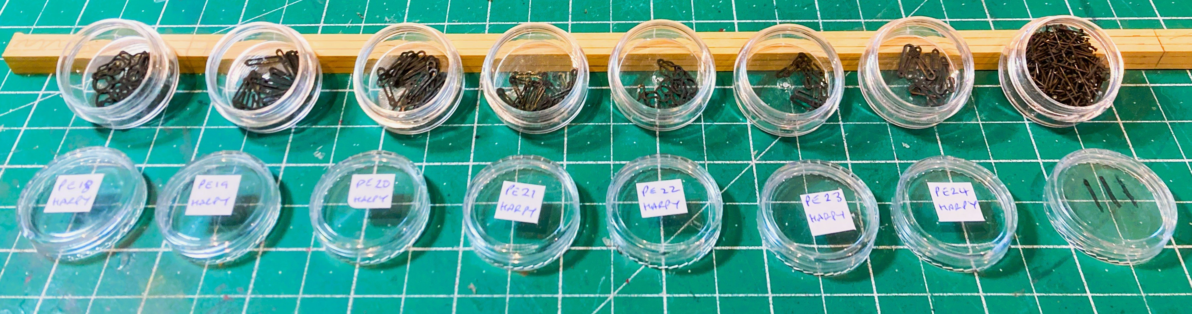
Post 73 Strops, chains, and plates. I prefer to chemically blacken ‘ironwork’ rather than paint it, as I think it gives a subtle and more realistic representation. 4105a It is more time consuming, and there are several parts that make up the strops and chain plate combinations. 4112a I test the assembled shroud combinations along the Channels to gauge where they fall on the Wale. The positions shown on the plan accord with those on the Adm plan. 4111a I may be missing something but I seem to have a potential problem; the lower link falls awkwardly right on the top edge of the wale, and the preventer plate sits too low on the wale. 004 Compared to the Plan the lower chain (pe20) seems over-long which throws the Preventer plate (pe21) too low. I have come across this issue on previous models where the answer is to adjust the upper chain link to bring the lower link and preventer plate to their correct placing, but a smaller lower link would be preferable. This does however involve a fair bit of faffing around to get the correct size. I am not in a position to fit the deadeyes at this stage as I decided to invest in resin versions in Swiss Pear colour, the latest innovation from Chuck’s Syren company. The basic kit blocks and Deadeyes are ok but lack the detail of what is now available. They also need sorting to weed out those with mis-cut holes etc; I’ve not picked up any indication of the need for adjustment, so I’m not sure what’s going on here, the wale is in the correct position as are the channels. B.E. 02/05/2025
- 332 replies
-
- 18
-
-
- Harpy
- Vanguard Models
- (and 1 more)
-
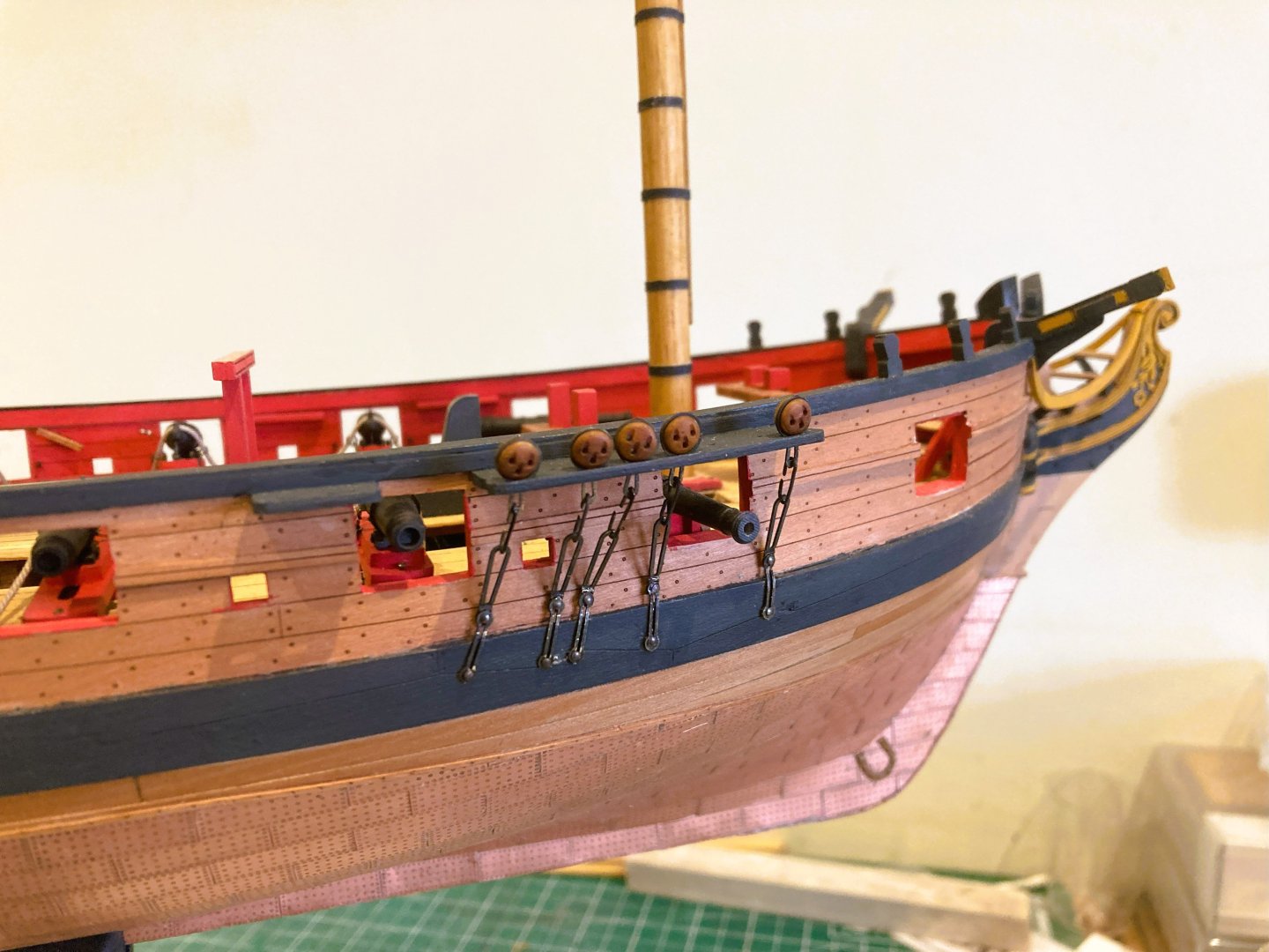
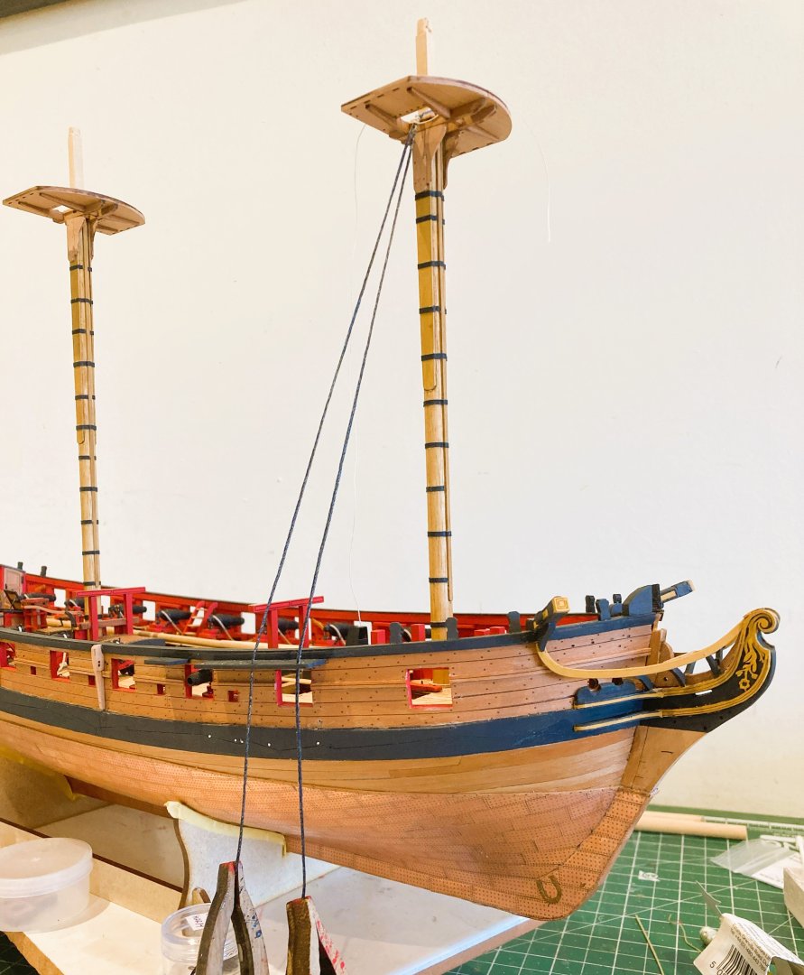
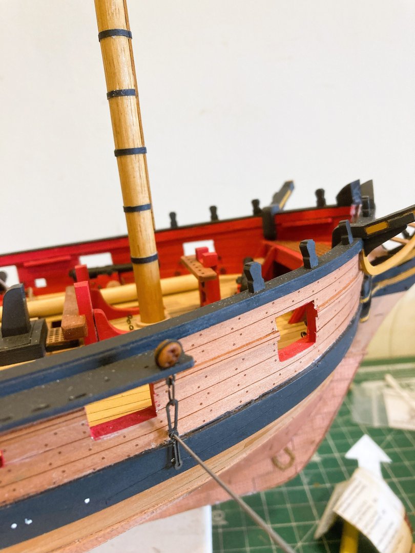
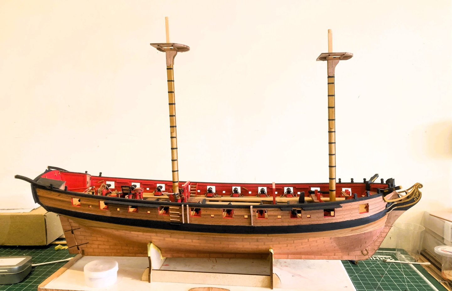
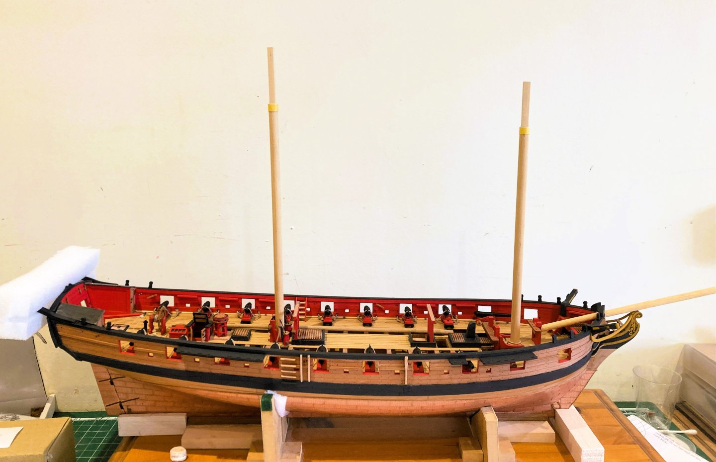
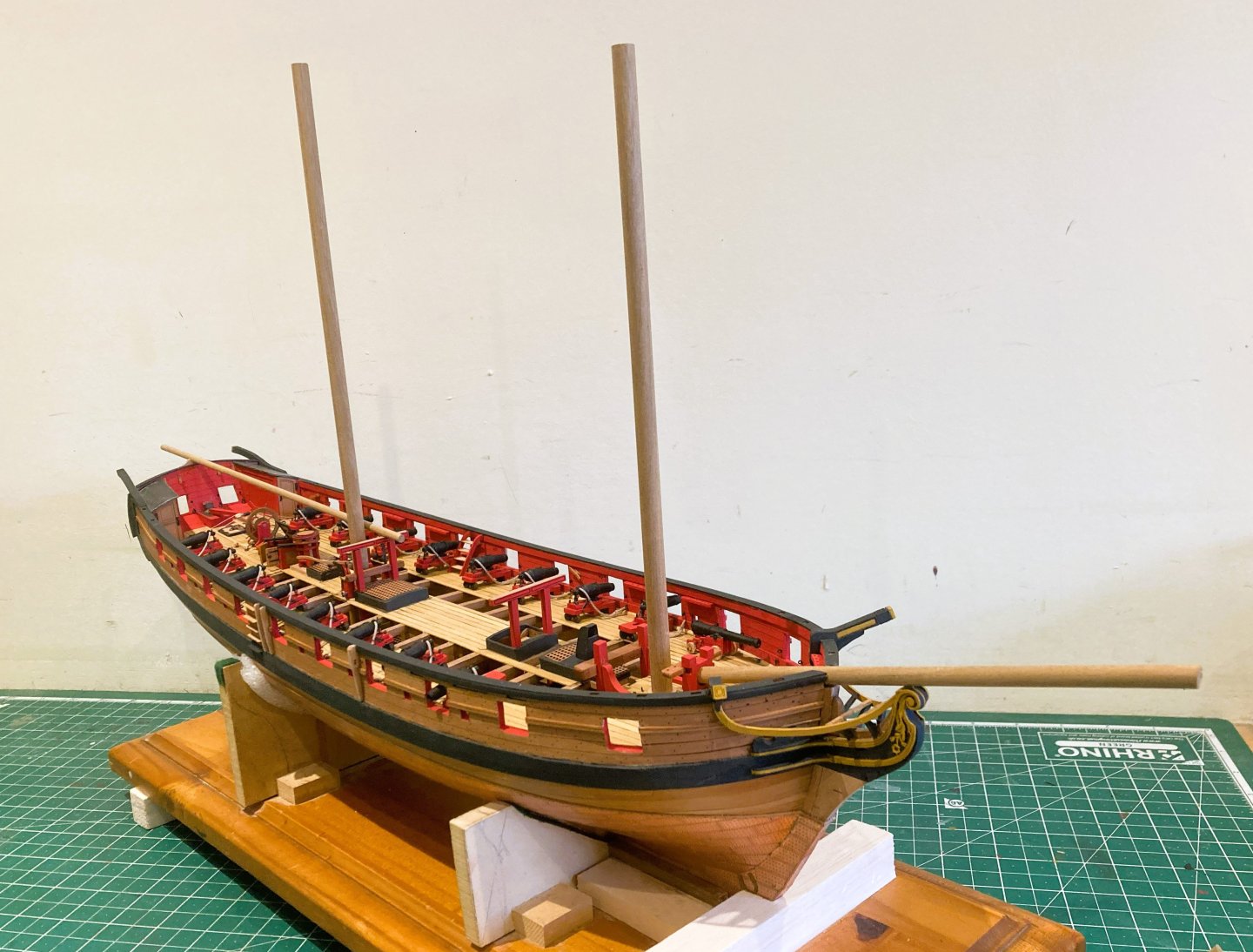
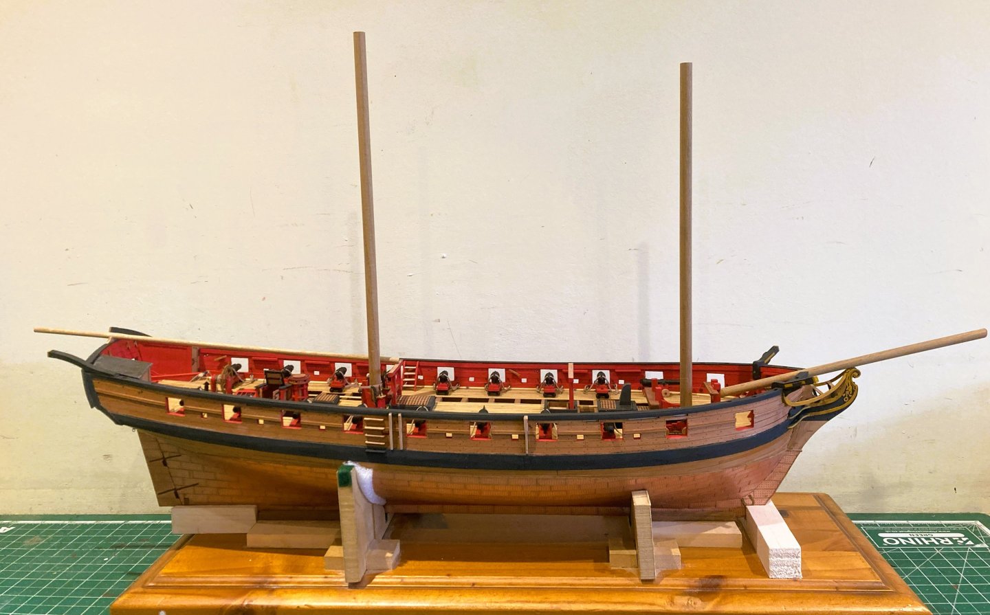
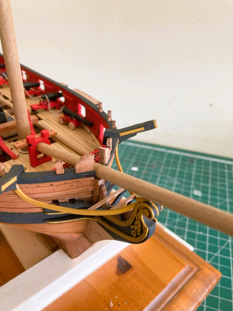
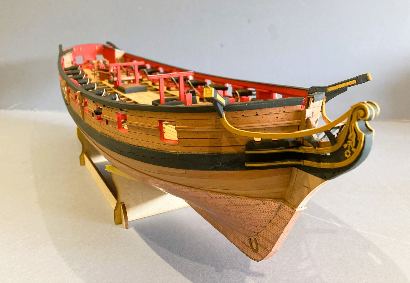
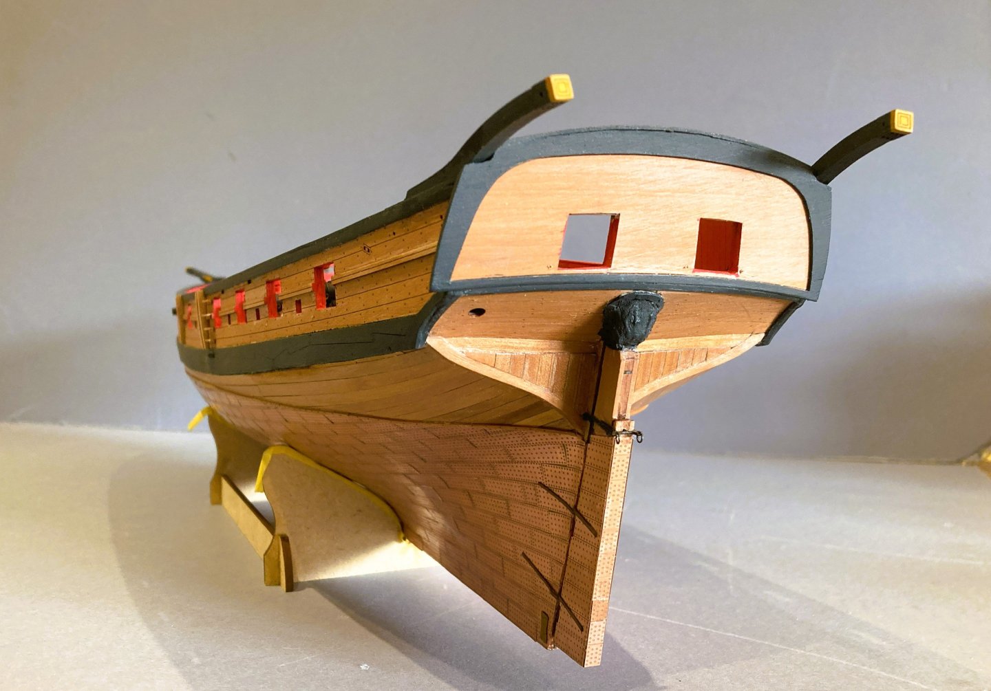
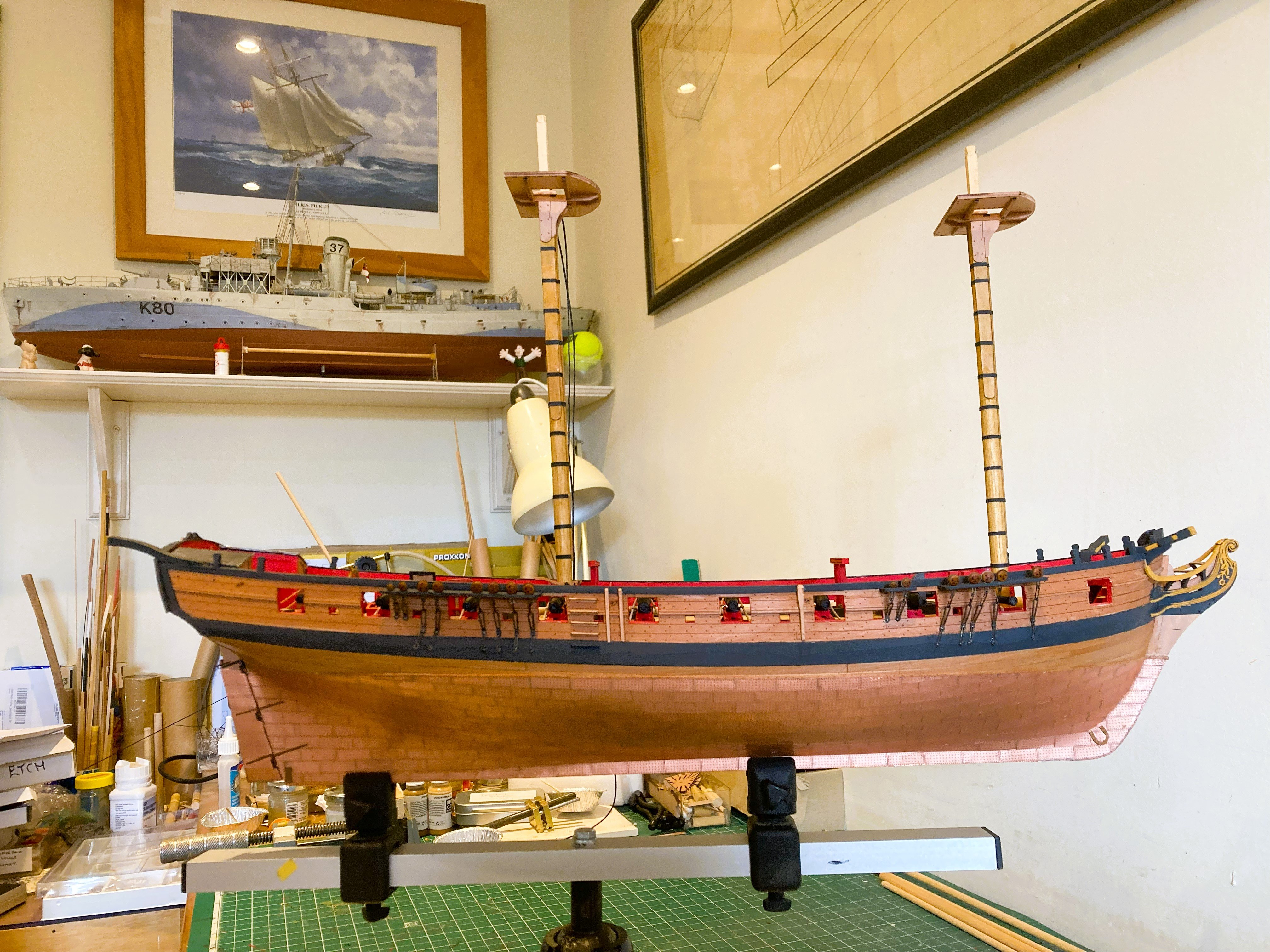
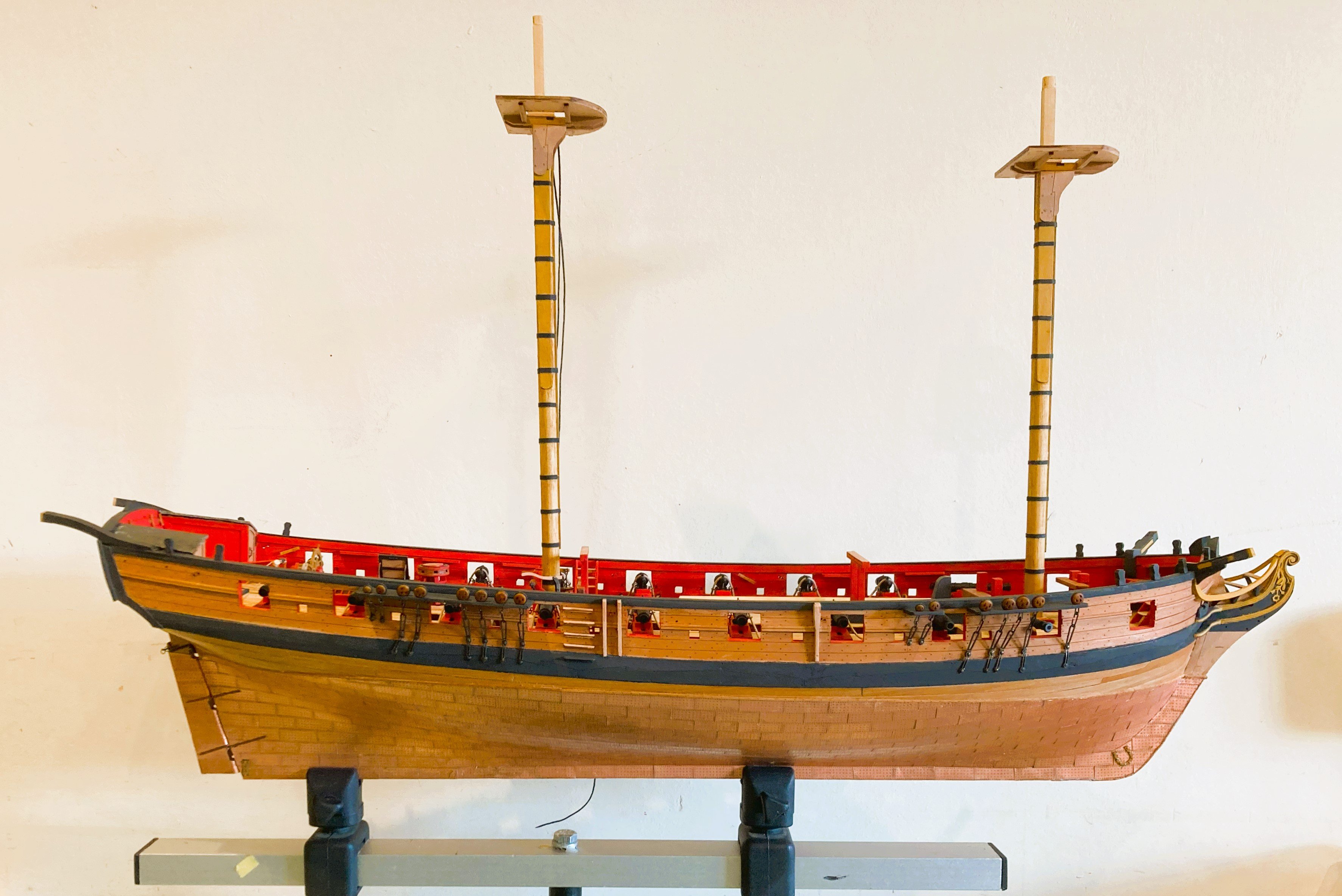
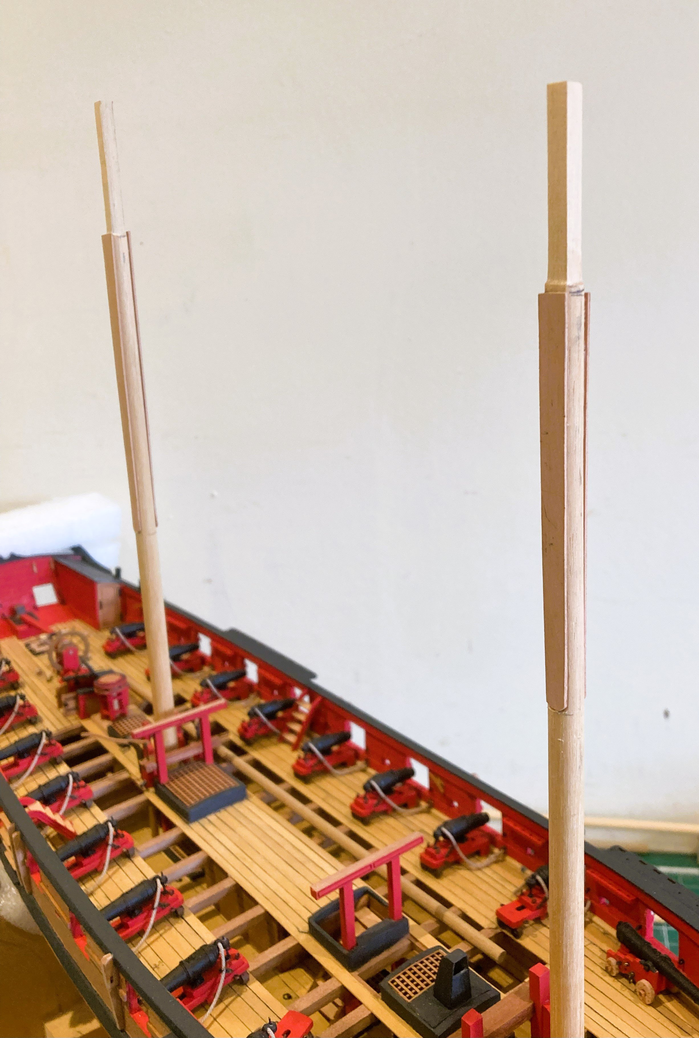
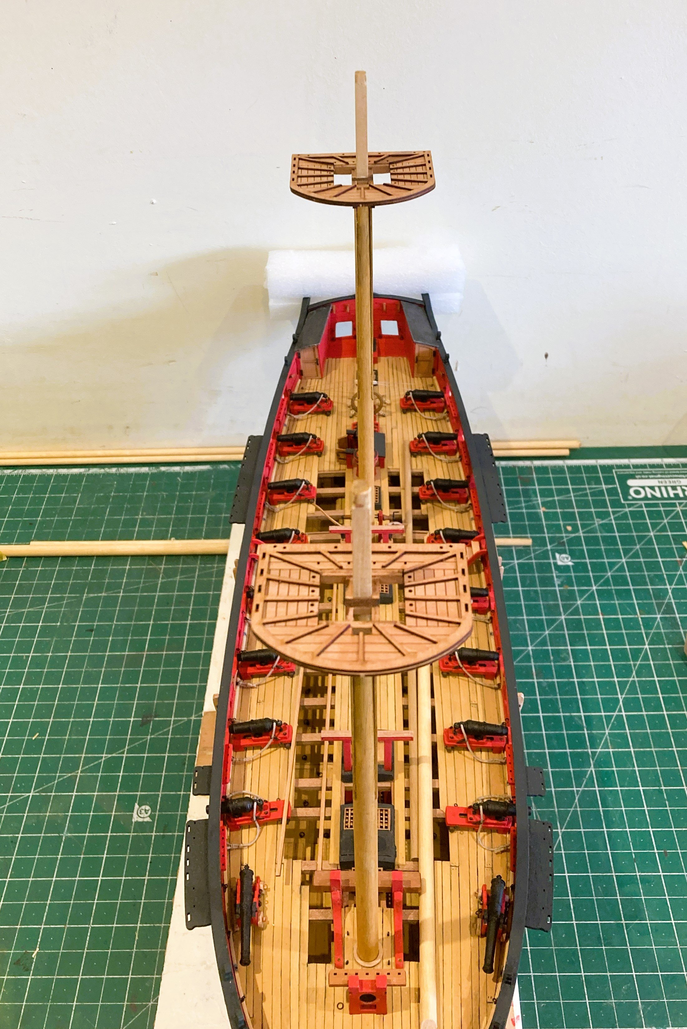
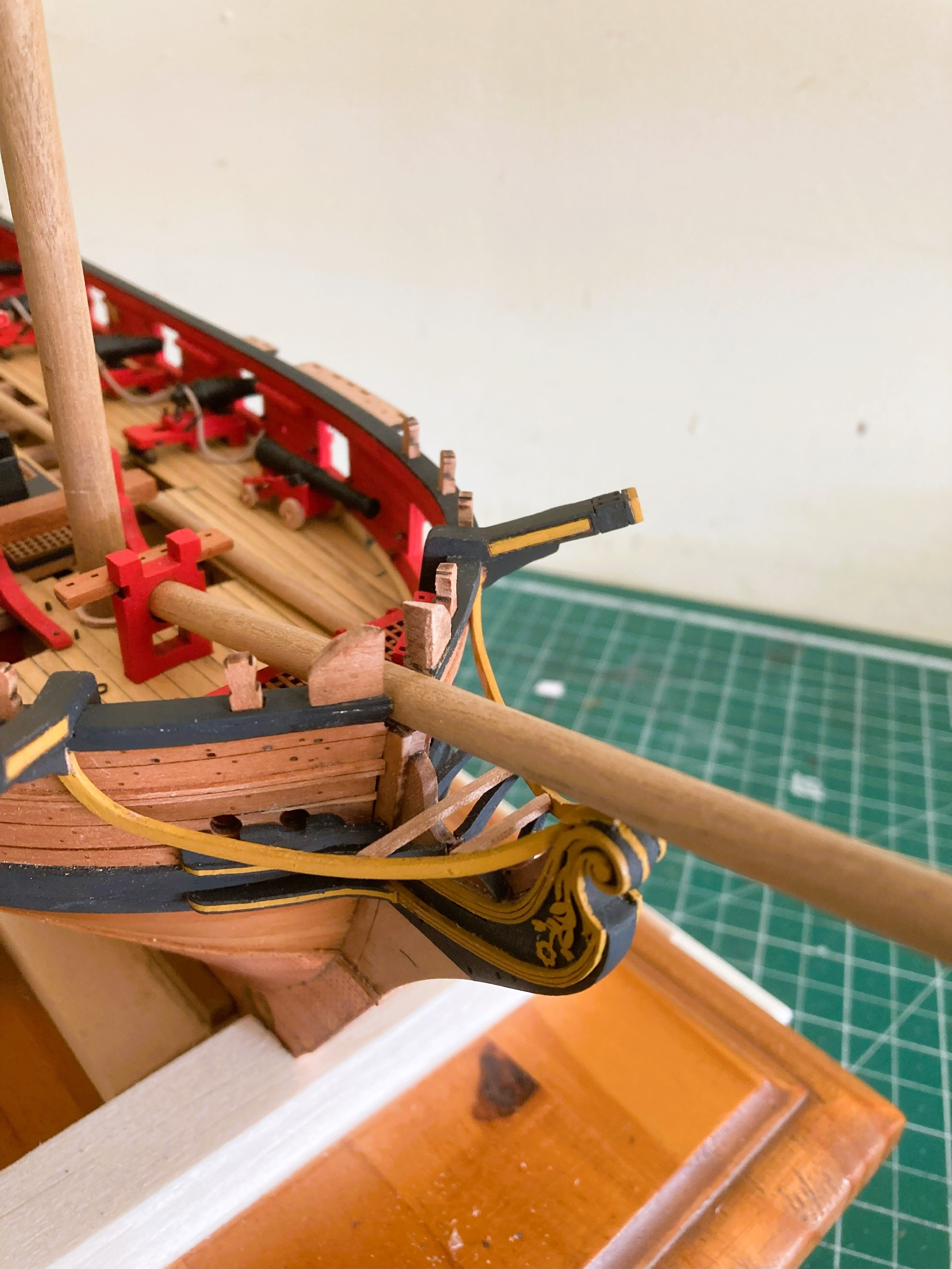
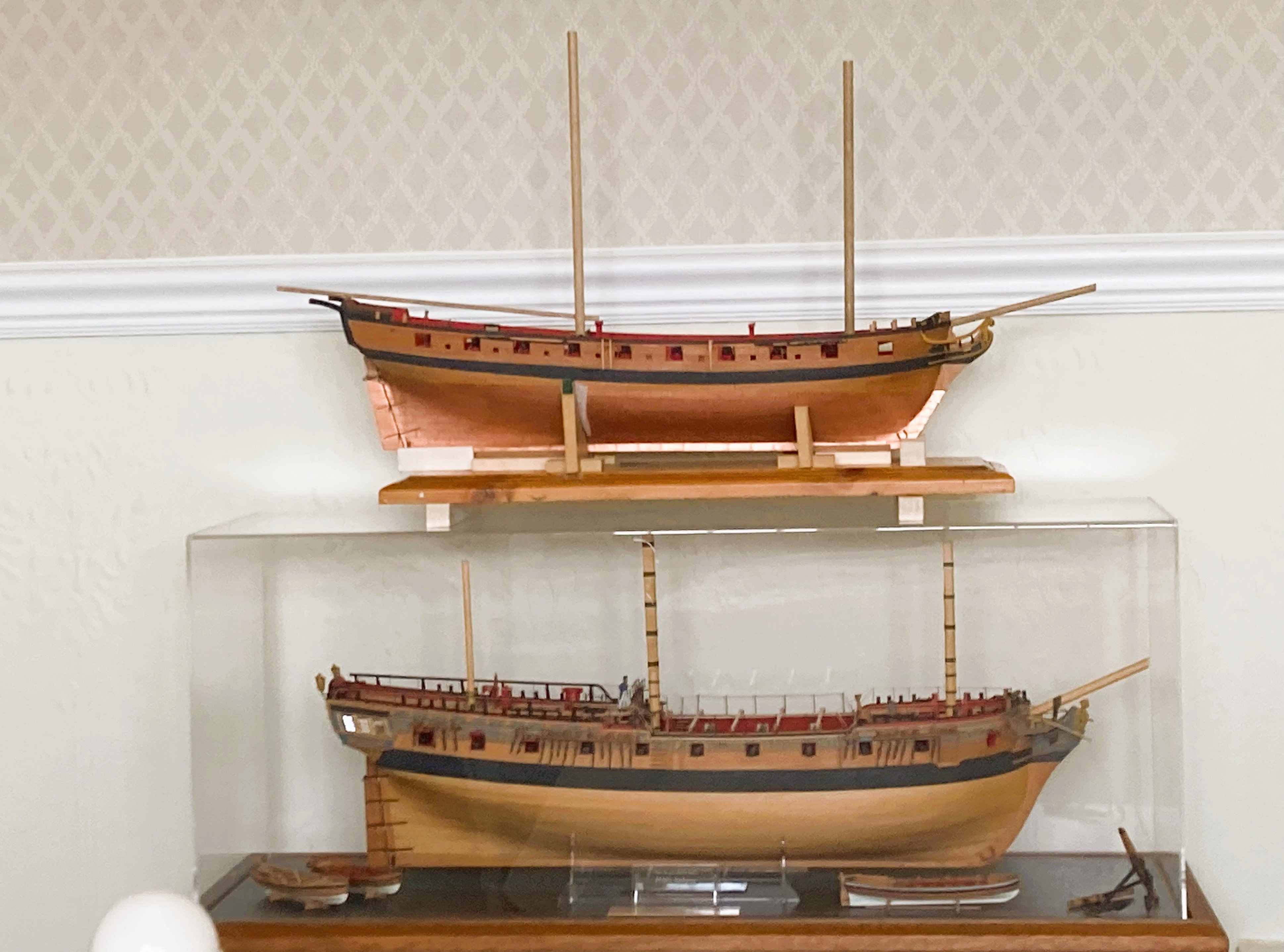
Post 72 Channels and Timberheads. These are the last main features to add to the hull exterior. 4084a 4085a Channels and Timberheads slot seamlessly into place. Side steps. 4102a Annoying but necessary little beggars these, two tiny pieces comprising a tread and support glued together at right angles, five required each side. Fortunately the locations are engraved on the top sides which helps with this exercise. With the use of laser cutters, shape and even a design is included on items that would prove very difficult to produce by hand accurately at this scale. 4079a The Bow bollards (275) referred to in the manual as Gunwale bow timbers sit either side of the Bowsprit. They are a less fancy version of the Knightheads that support the Bowsprit. These need bevelling on their inboard faces to run parallel to the Bowsprit. I have made up some test masts and spars to gauge the overall size were I to detail the lower masts and standing rigging. 4068a These are the full length Masts, Bowsprit, and Driver boom, as per the plans. How they relate to Steel I haven’t checked at this point. 4070a The masts are in Walnut but I prefer Ramin for lower masts. 4090a This is the space profile compared to Sphinx, I think I can accommodate her with lower rigging in place but without the yards. Decision made. B.E. 30/04/2025

- 332 replies
-
- 23
-
-
- Harpy
- Vanguard Models
- (and 1 more)
-
Congratulations ECK, 15 weeks from keel to completion, Chris is going to have to up his output to keep pace with your build rate.😉 She looks a fine model, almost tempts me to fully rig her. B.E.
- 73 replies
-
- 2
-
-

-
- Harpy
- Vanguard Models
- (and 1 more)
-
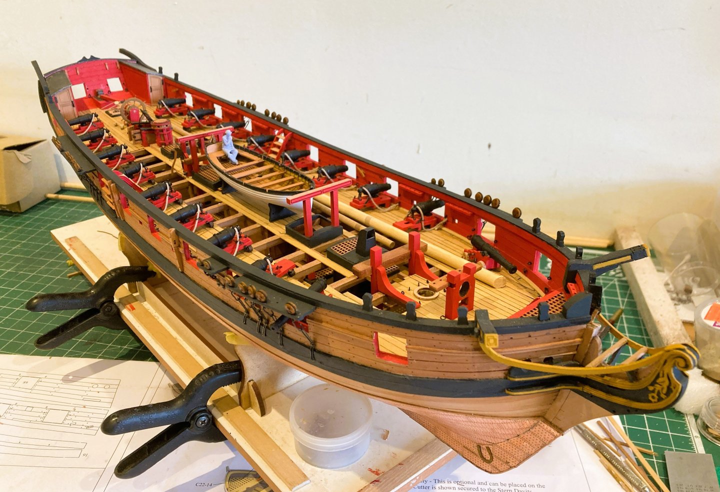
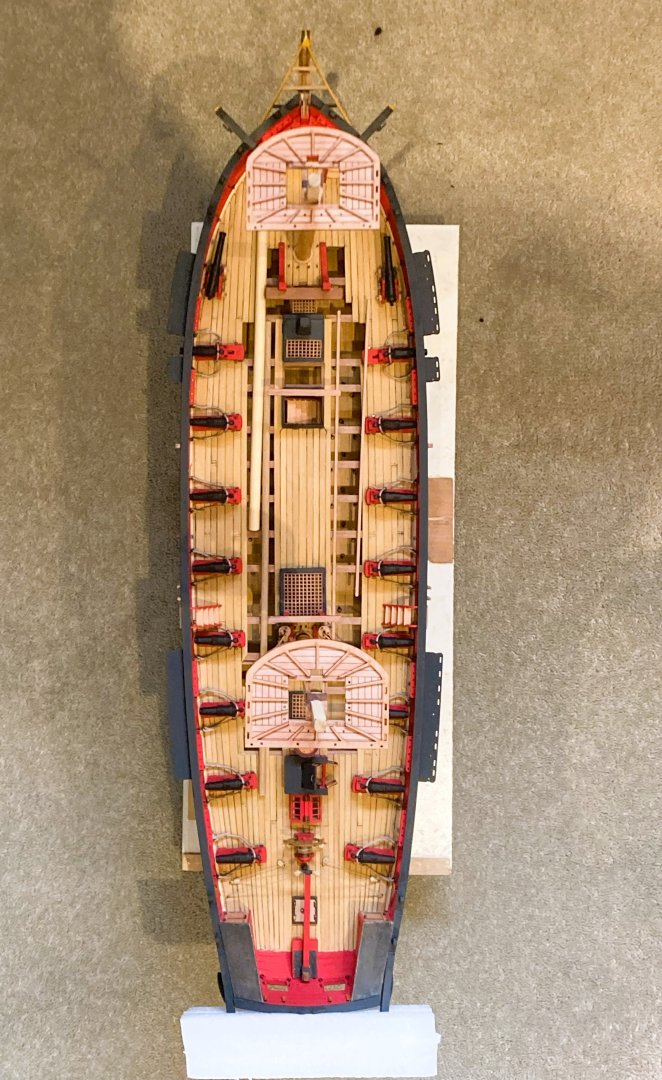
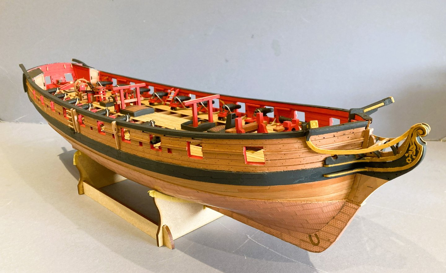
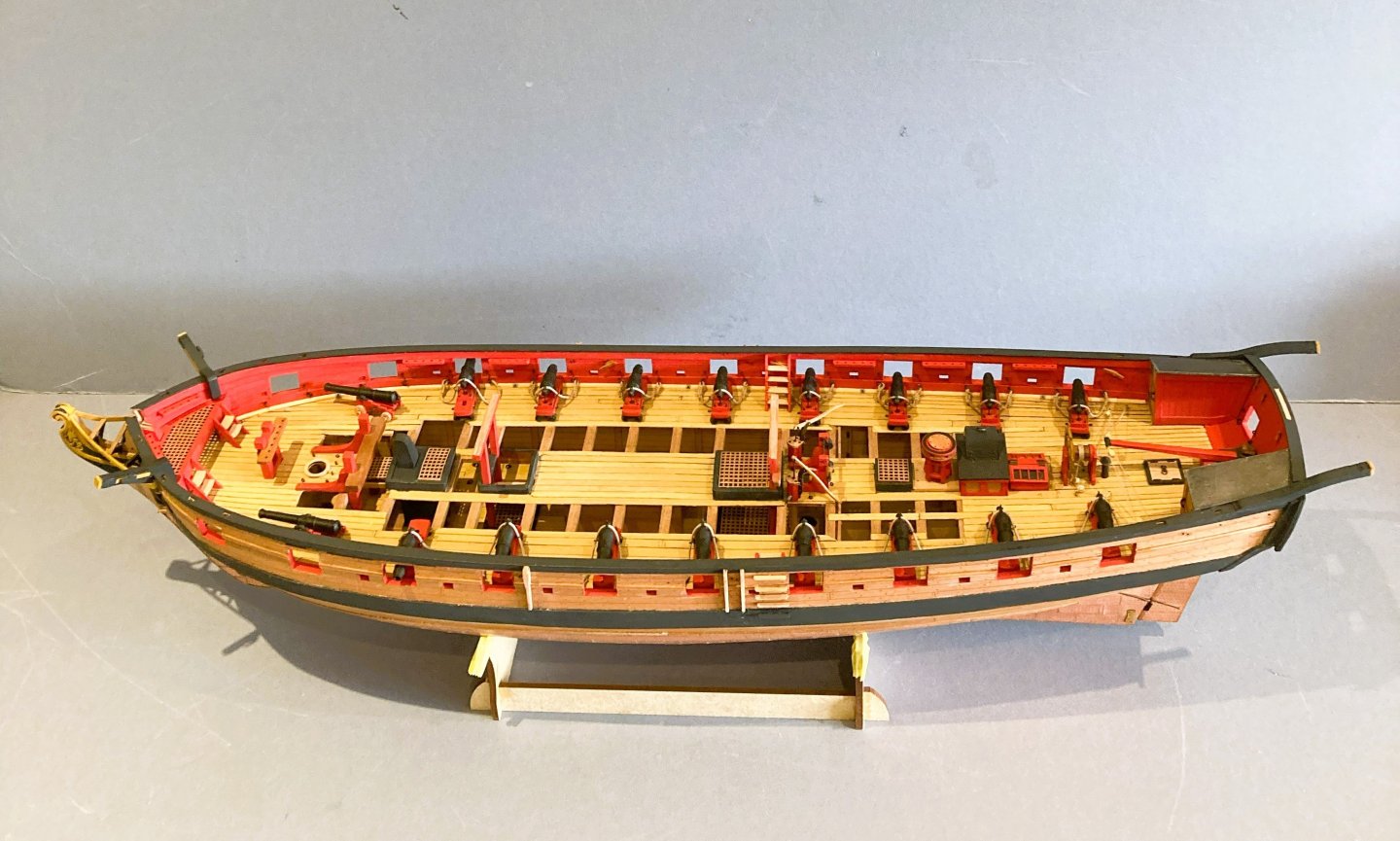
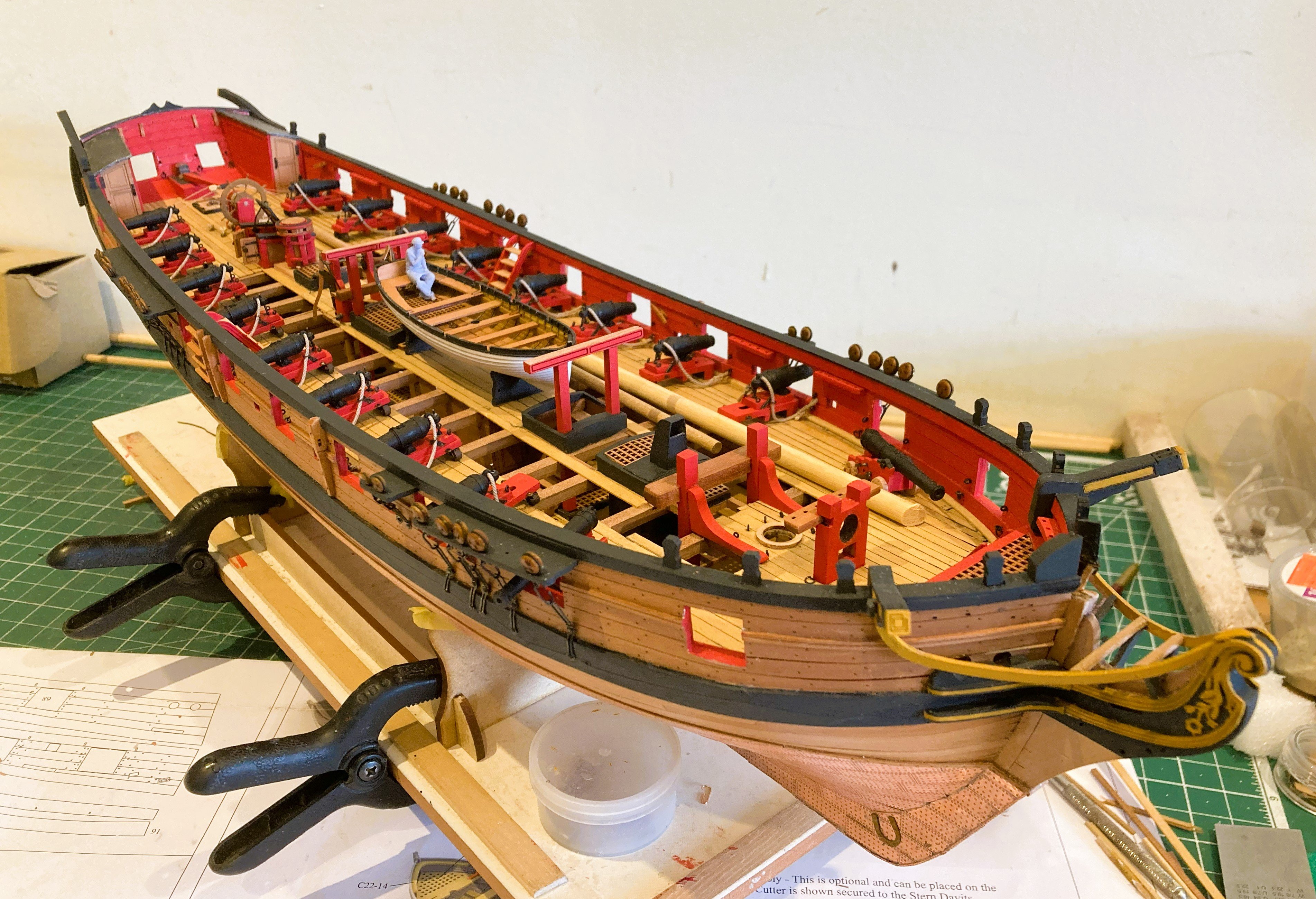
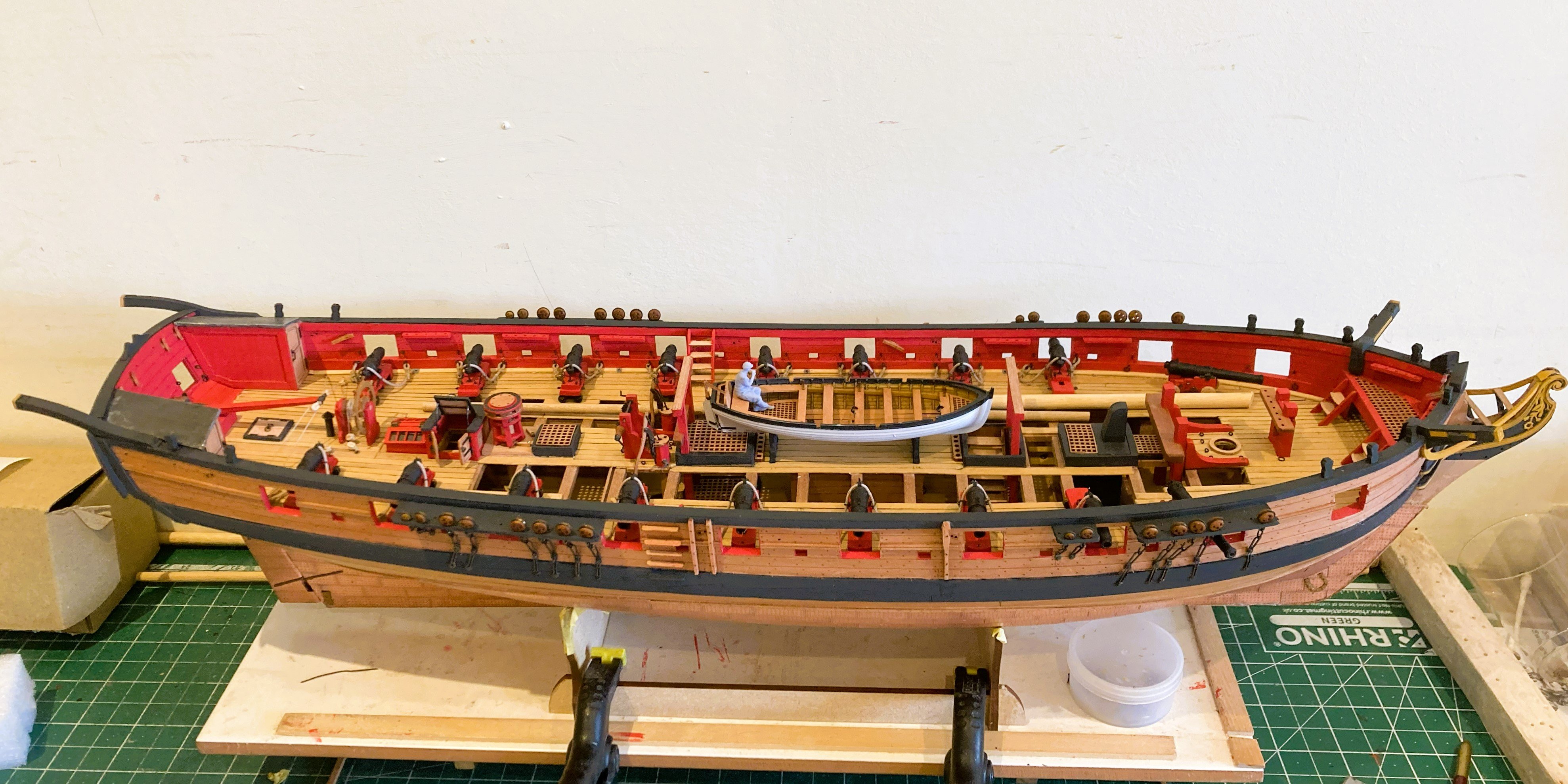
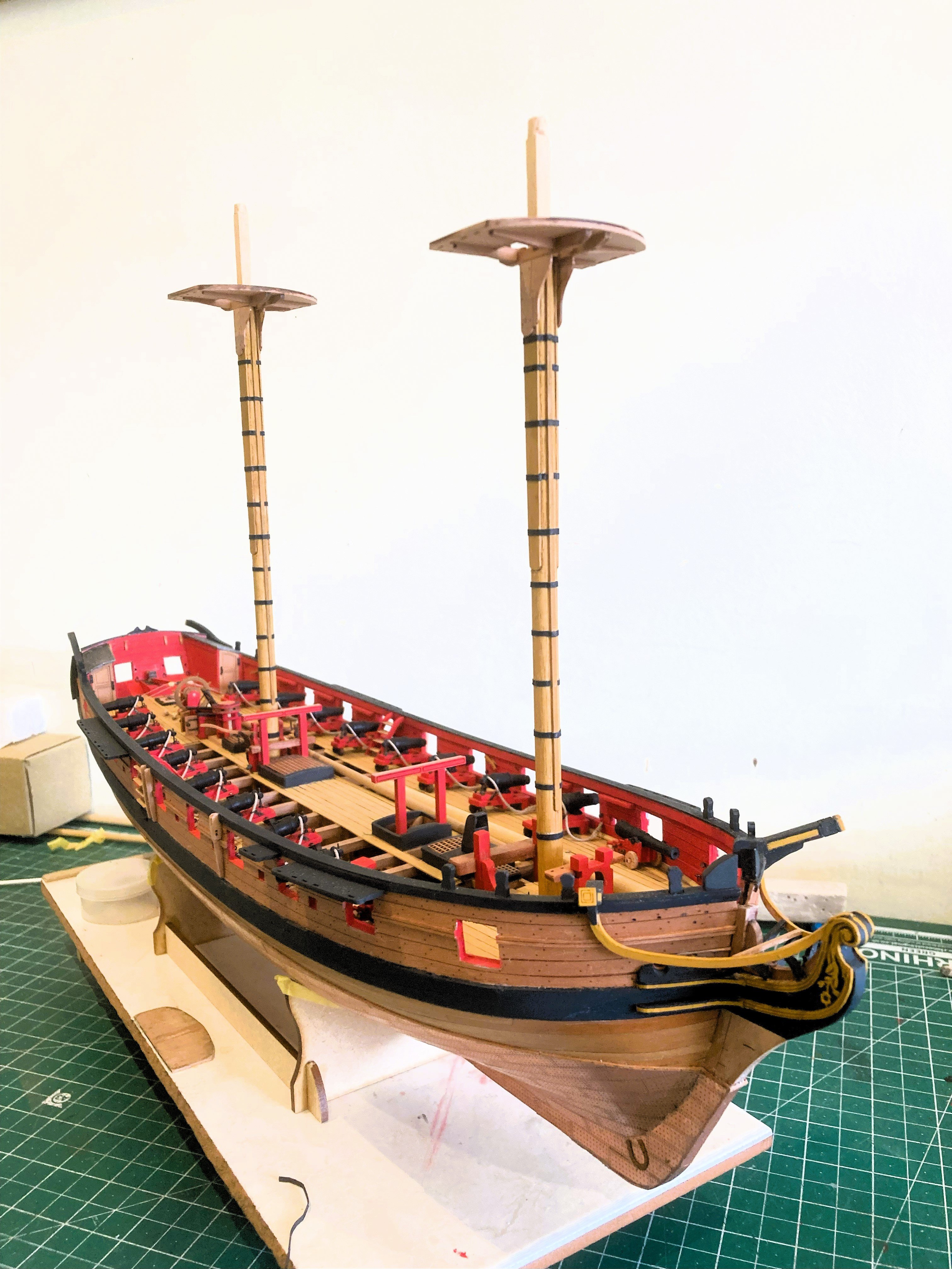
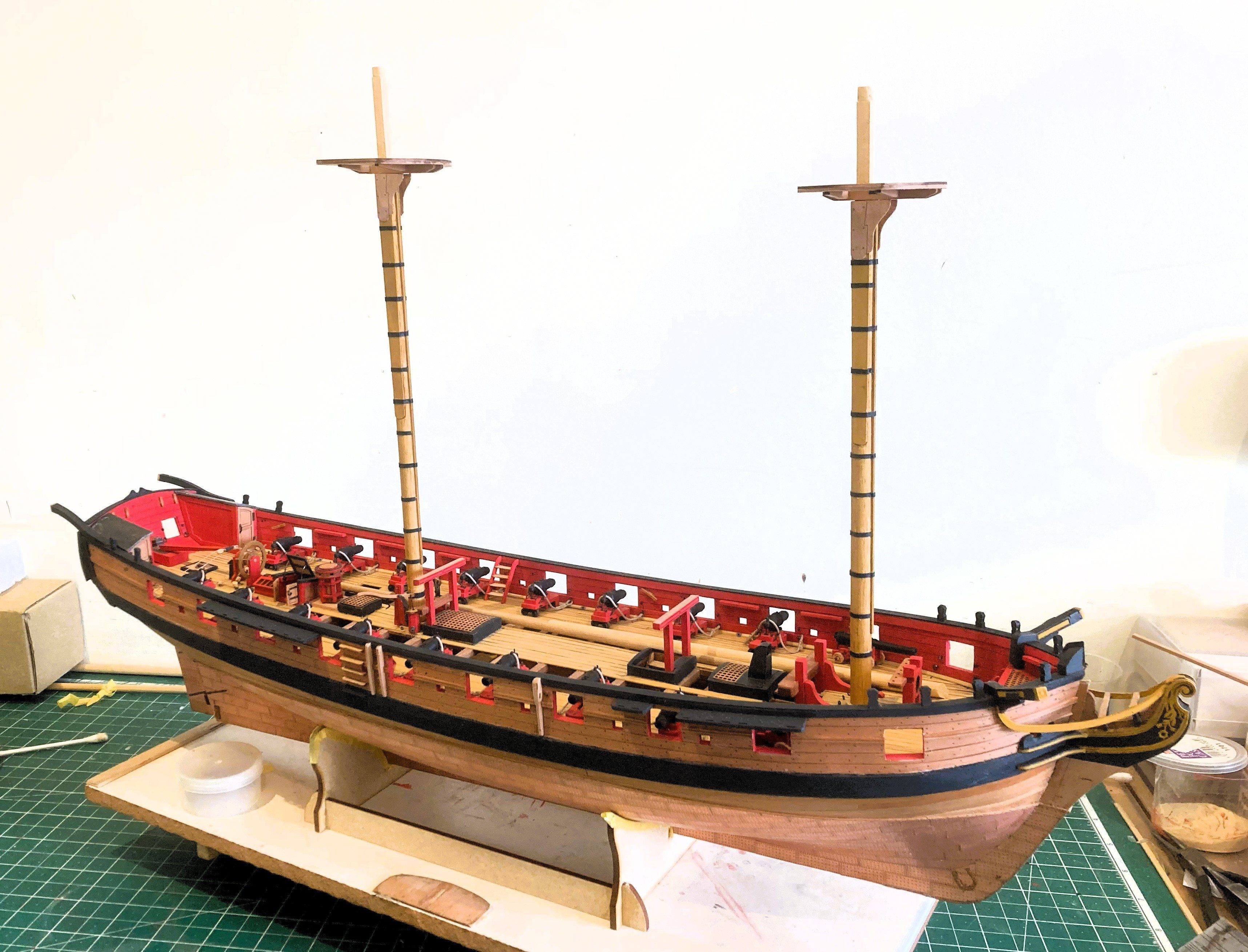
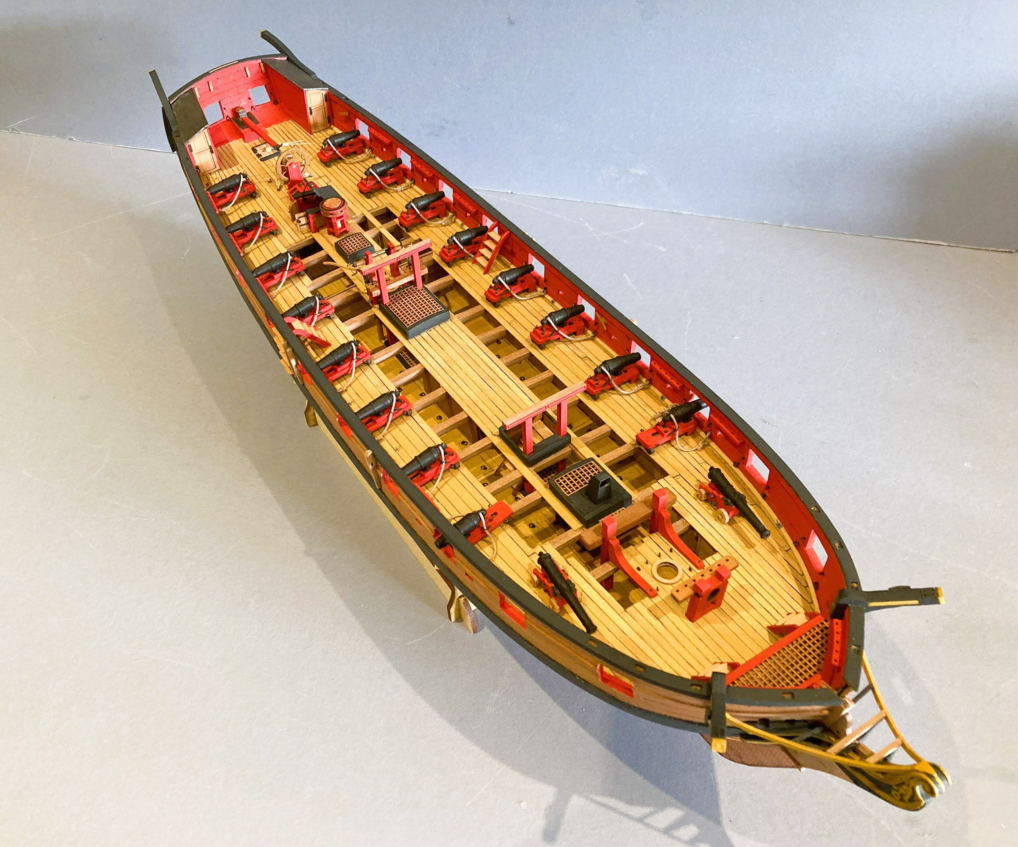
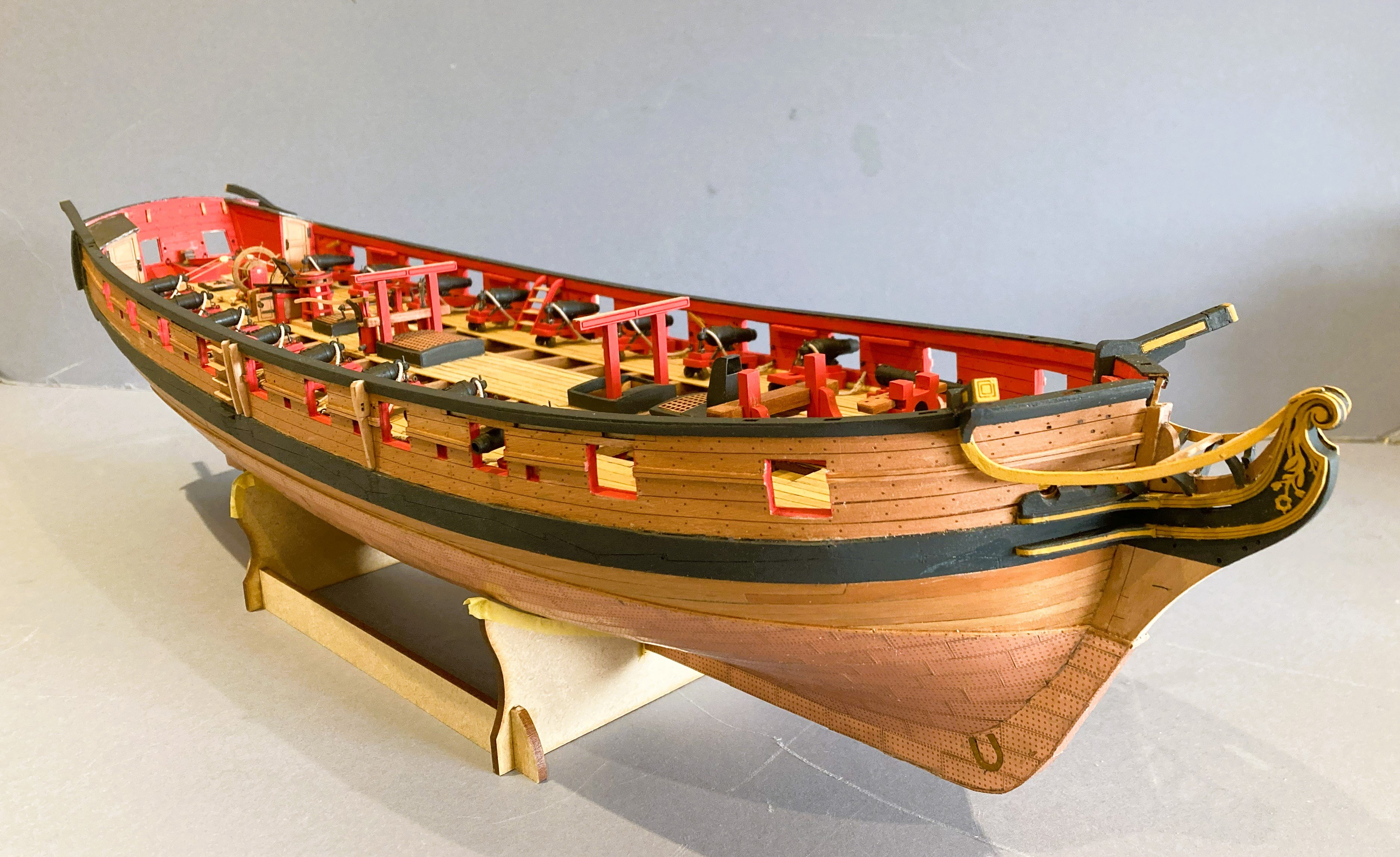
Post 71 Completion of first stage. Five months into this build and time for a long overdue workshop GTU, and some stage photos. 4042a 4041a 4044a 4046a 4048a 4049 4053a 4056a 4061 4057a 4054a I now need to decide where I’m going with this build. I completed my previous two builds ‘Navy Board’ Style with stump masts, but I am leaning towards going a little further with Harpy. My initial thoughts are to rig her with lower masts and standing rigging in place but without yards. 011a I did this with my model of Victory. I quite like this set-up on models and it has the advantage of space saving. With Harpy, extending the build time, and deferring any concerns of what to do next are also a factor, and I fancy doing some rigging again. I will start with a mock-up to gauge the overall space requirements, and then, once Mrs W has left the premises, wander around the house looking where it will fit in. A plan of sorts. B.E. 28/04/2025


.thumb.JPG.6a99aad5be73beb2c1aabd44681c7ae4.JPG)
- 332 replies
-
- 26
-
-
-
- Harpy
- Vanguard Models
- (and 1 more)
-
Nice work on those masts Glenn, not an easy task making a good job of squaring the mastheads from dowel. B.E.
- 241 replies
-
- 5
-
-
-
- Vanguarrd Models
- Harpy
- (and 1 more)
-
Excellent work Ronald, it looks spot on👏 B.E.
-
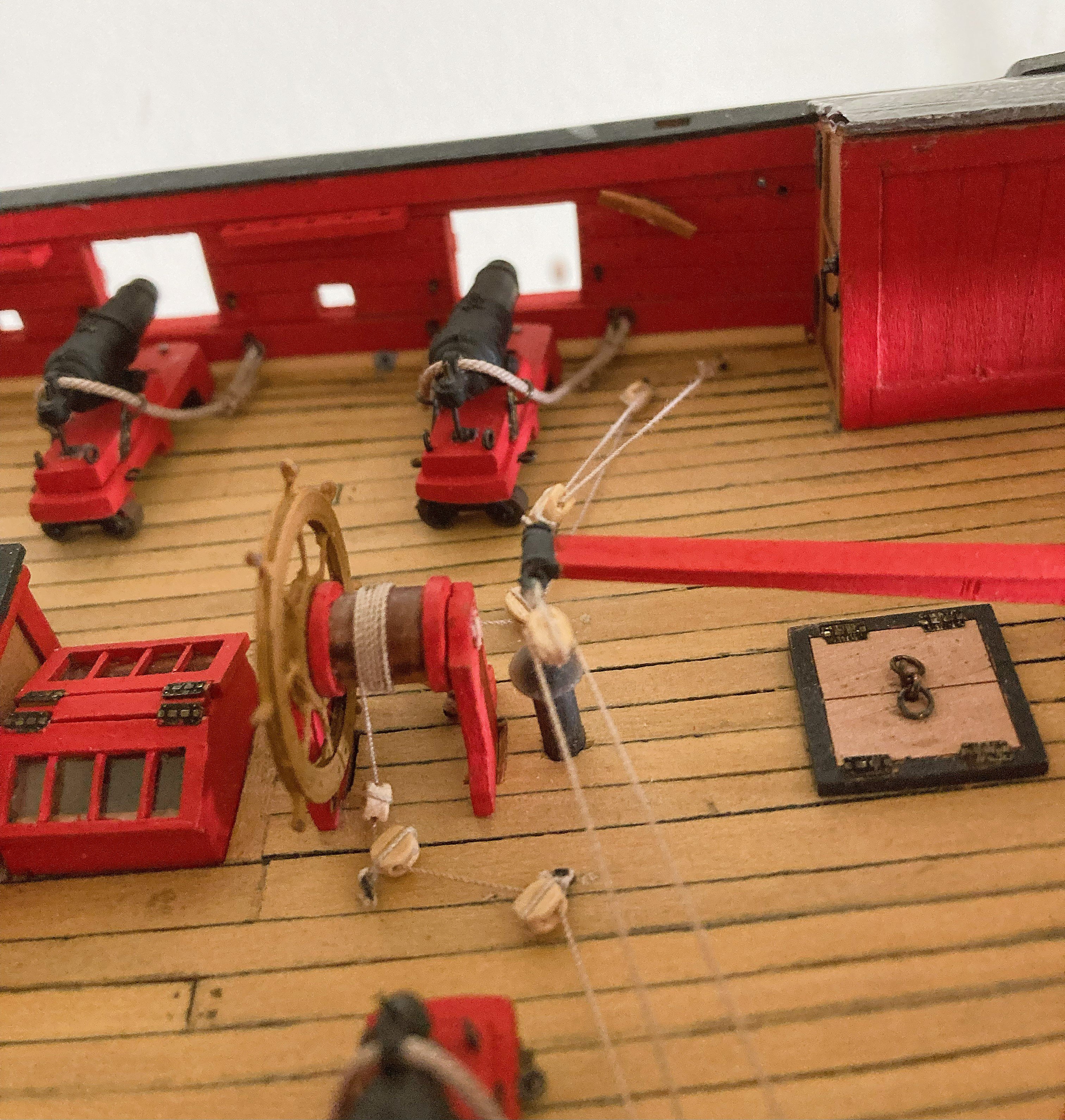
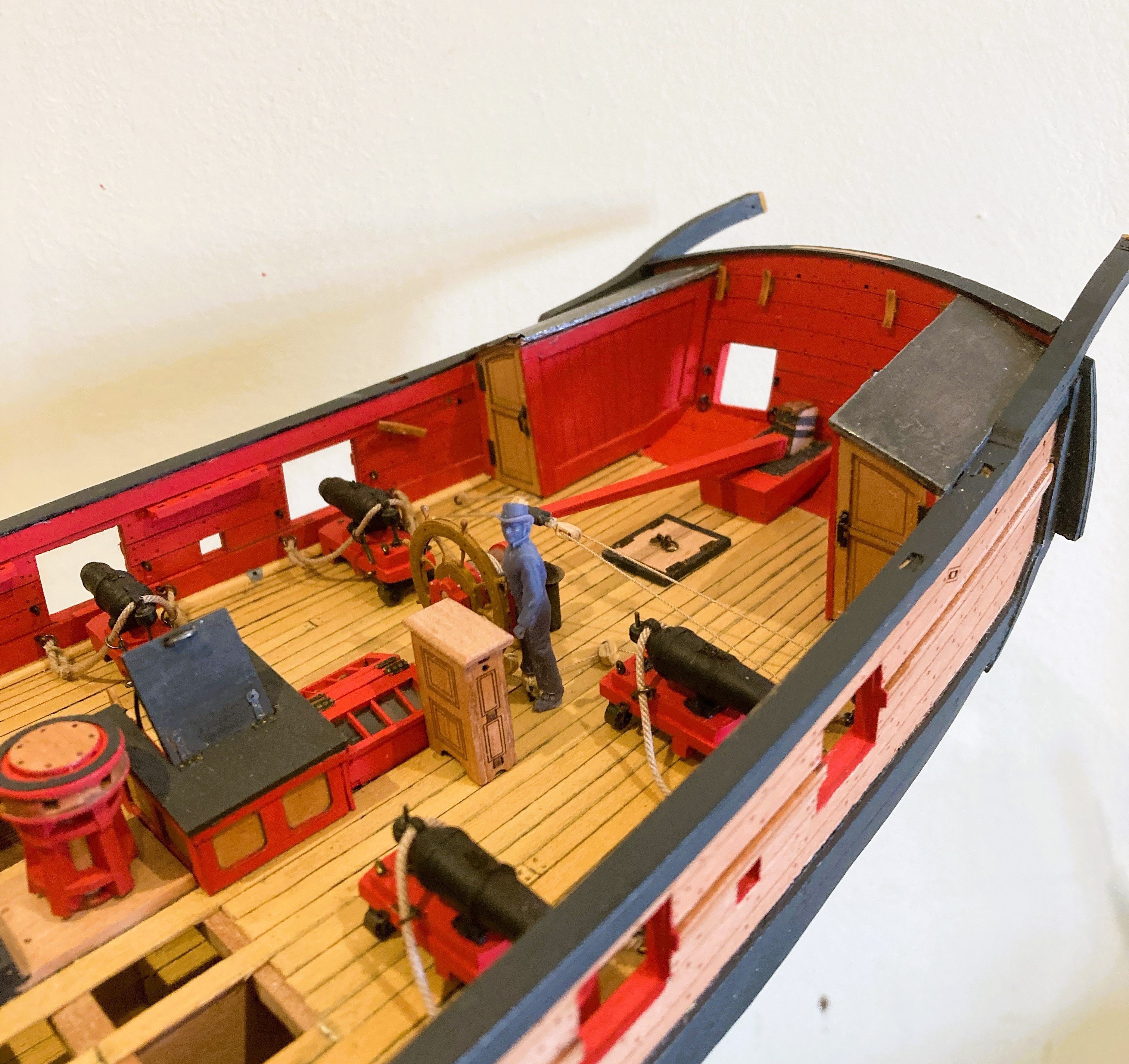
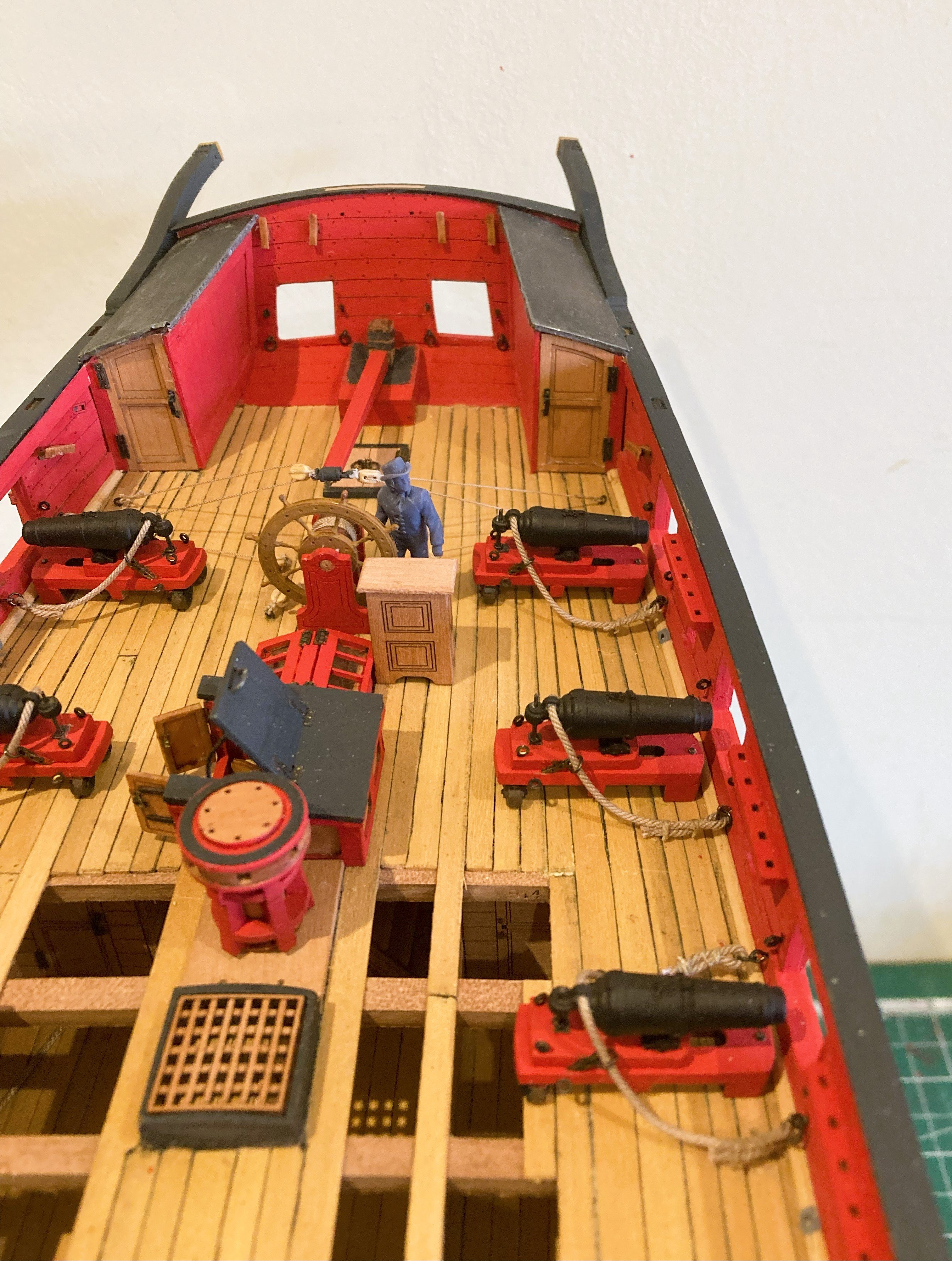
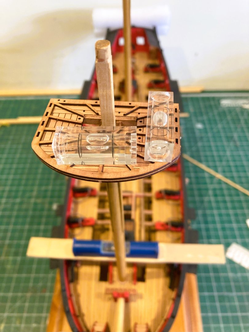
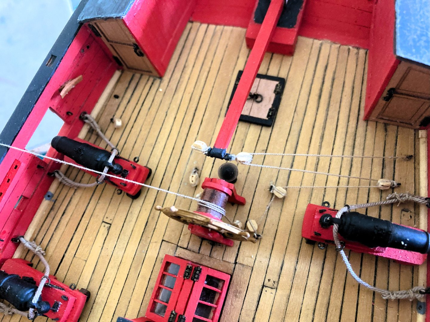
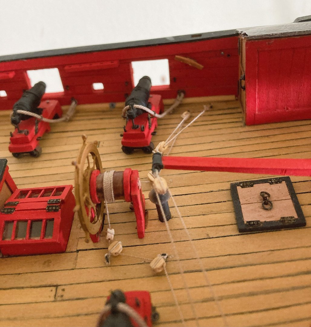
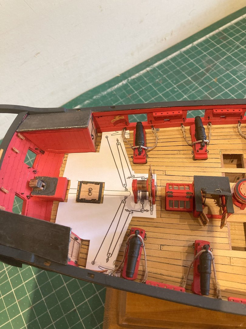
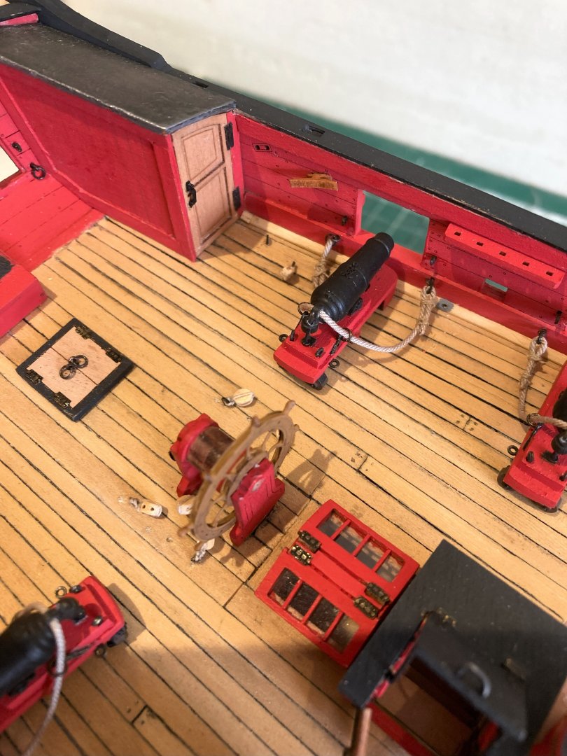
Post 70 Rigging the Wheel Steel indicates 3” circ line for the tiller lines which equates to a scale diameter of 0.37mm. The kit plans suggest a 0.25mm line, but I am using 0.3mm Syren line. I start on the Port side where the line meets the wheel drum on its forward end. Sufficient line is required to complete the entire process. 4021a I firstly secure the line to the aft deck eyebolt off-model. A false splice is used for neatness. 4023a The line then runs to the tiller and back thro’ the deck blocks (in the correct sequence) and up to the wheel drum on the forward end. Care needs to be taken to ensure the line is fed thro’ the correct hole in the blocks. Three turns of the line around the drum, with a spot of ca at the centre of the third turn atop the drum. Before this is done the lines are checked for tautness throughout the Port side set-up. Given the length of the line care is also required when feeding it thro’, there are many snag points on the surrounding fittings which may be dislodged if caught when the line is pulled thro’. 4030a I have used six turns of line in total around the drum because this best matched the block arrangement. It is a common novice mistake to wrap the line around the drum as many turns as it will take. Five or six turns would be appropriate on smaller vessels, Victory had nine. 4029a Must have been very annoying stepping over the tiller lines to gain access to the stern. I last looked at the Binnacle in Post 54, but I’m no closer to a decision where or whether to place it. It makes no sense to me to have a Binnacle where the Helmsman can’t see the compass, and a unit with a chimney without a lamp compartment. I tried the double cabinet but the unit seems too close to the wheel and the viewing of the compasses is still obscured by the wheel. My inclination is still that the small cabinet slightly offset to the side of the wheel is the practical option. Being an important piece of kit it would be removed below deck in the event of an approaching action. 4033a Small single Binnacles do feature in ships of the first quarter of the 19thc often one each side of the wheel, but I can’t find any examples of this cabinet style (above) positioned as it is. 4035a Historical museum ships and some contemporary models all show a centrally placed cabinet before the wheel, but there is more space between the wheel and the cabinet; with Harpy the binnacle is hard against the wheel stanchion. 4036a 4039a The Helmsman looks quite comfortable with the arrangement, but my dithering continues..... B.E. 25/04/2025


- 332 replies
-
- 22
-
-
- Harpy
- Vanguard Models
- (and 1 more)
-
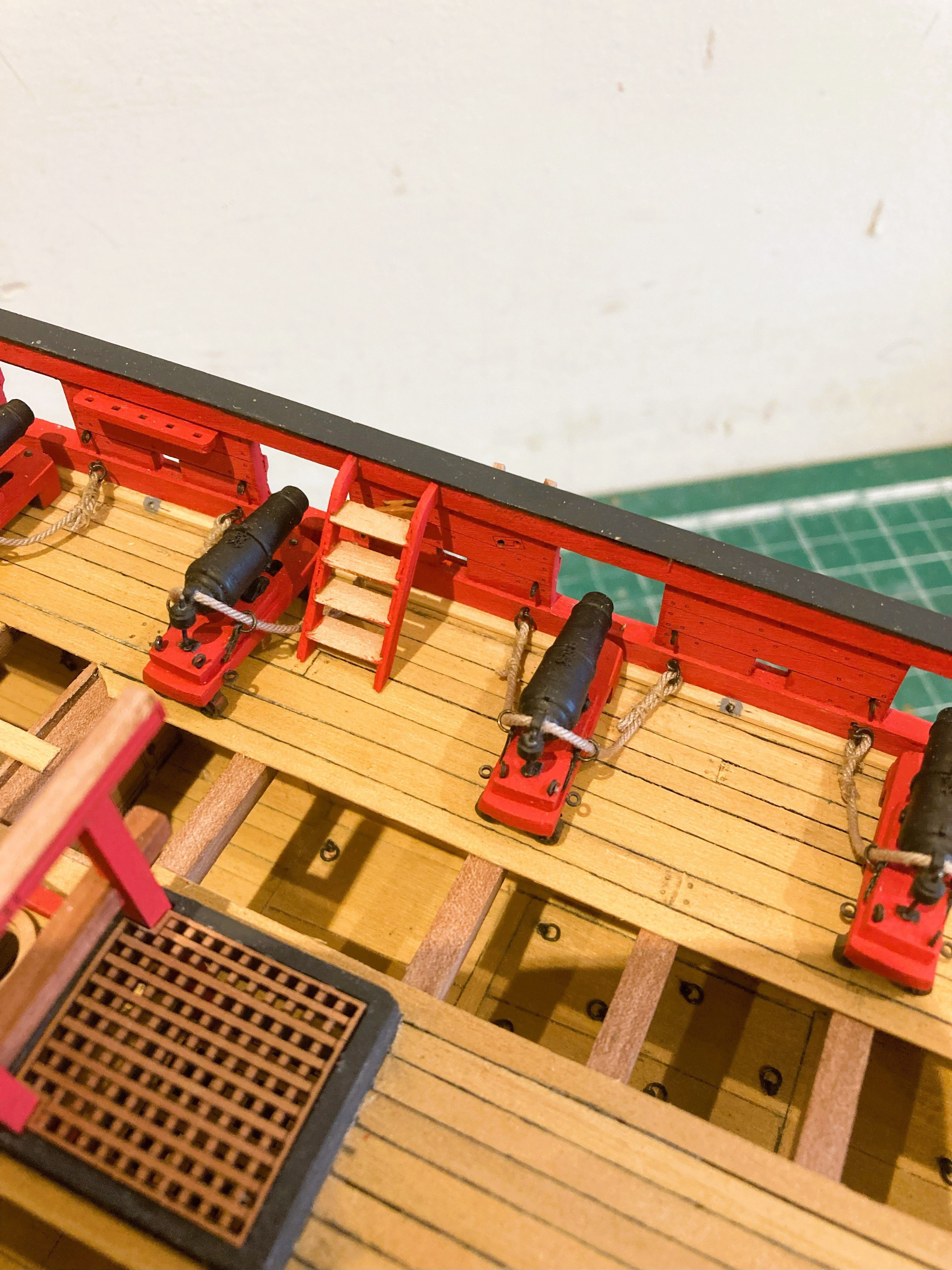
Those particular cleats will be for belaying the Fore sheets which enter thro' the fixed blocks on the side. Best not to fit those ladders until that is done, it would be difficult to make a nice finish to the belay and line ends with the ladders in place. The pump handles are a snag point, but I don't glue the pumps in place, no need with the elmtree extensions into the lower deck. I tend to glue as little as possible on my models for ease of removal if required, this includes the masts and yards. B.E.
- 332 replies
-
- 2
-
-
- Harpy
- Vanguard Models
- (and 1 more)
-
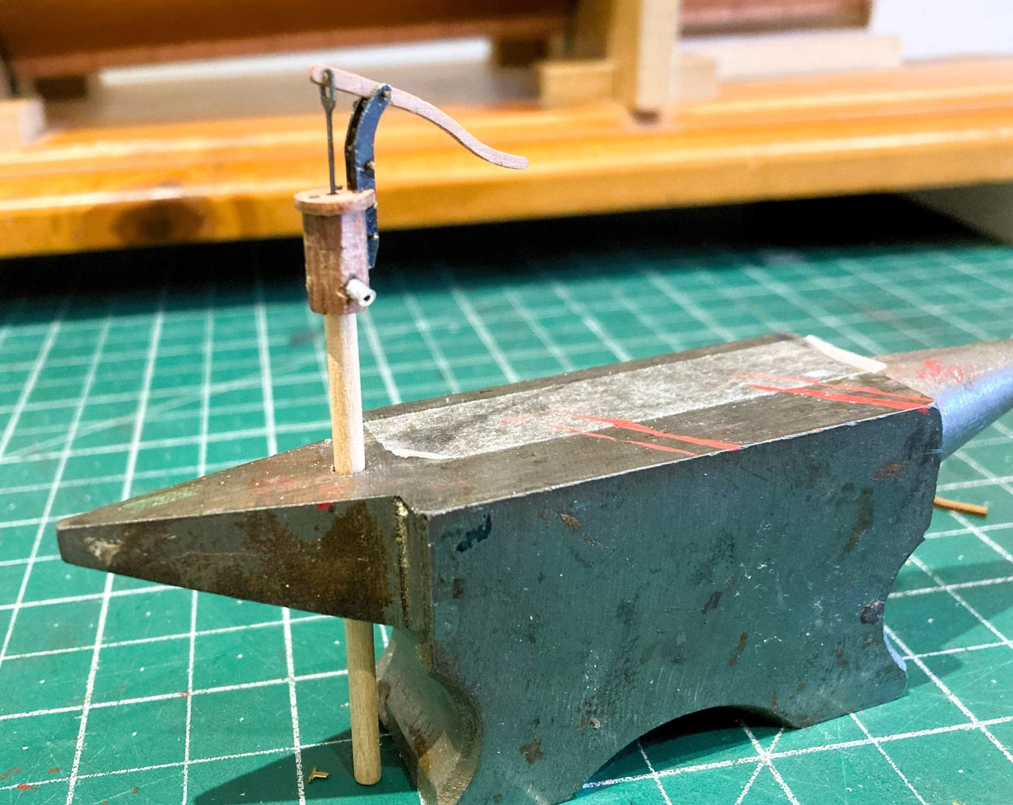
Post 69 Deck fittings cont’d Brake Pumps A pair of these are the only means of clearing the bilge on Harpy. 3999a They are nicely designed with hexagonal pump bodies and fine brass etch attachments. With the open unplanked decks of Harpy the ‘elm tree tubes that run down thro’ the decks to bilge are on view. 4004a Trickiest part of assembly is blackening and gluing the brass etch parts together without destroying the surface finish. I added ‘lead’ discharge pipes to the pumps. 4009a 4011a 4012a Getting to look quite busy on the deck. Internal Bulwark ladders. These don’t receive a mention until very late in the manual (Section 491) but they are made up as per the other ladders using parts 70 -73 from the 0.6mm laser sheet. 4007a 4008a 4017a Now, about those tiller lines…. B.E. 24/04/2025


- 332 replies
-
- 22
-
-
- Harpy
- Vanguard Models
- (and 1 more)
-
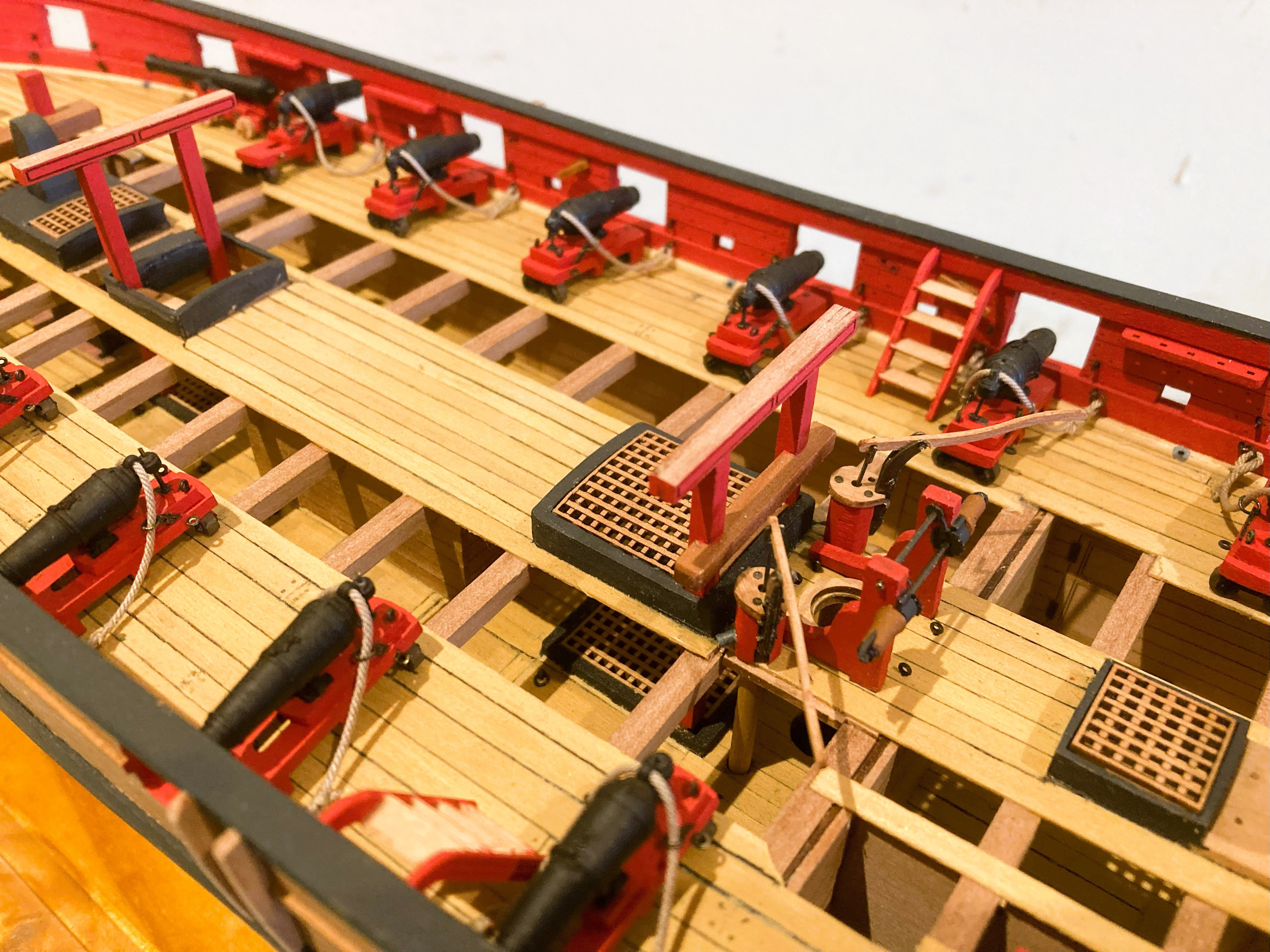
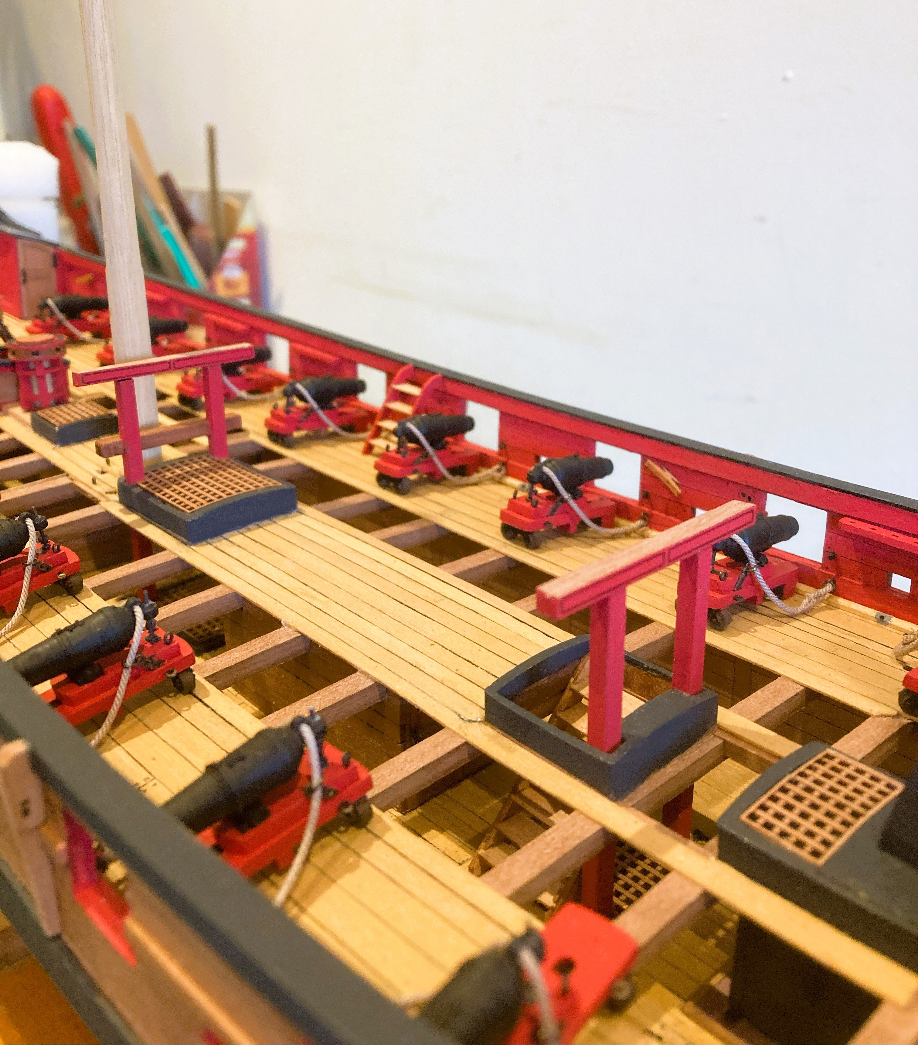
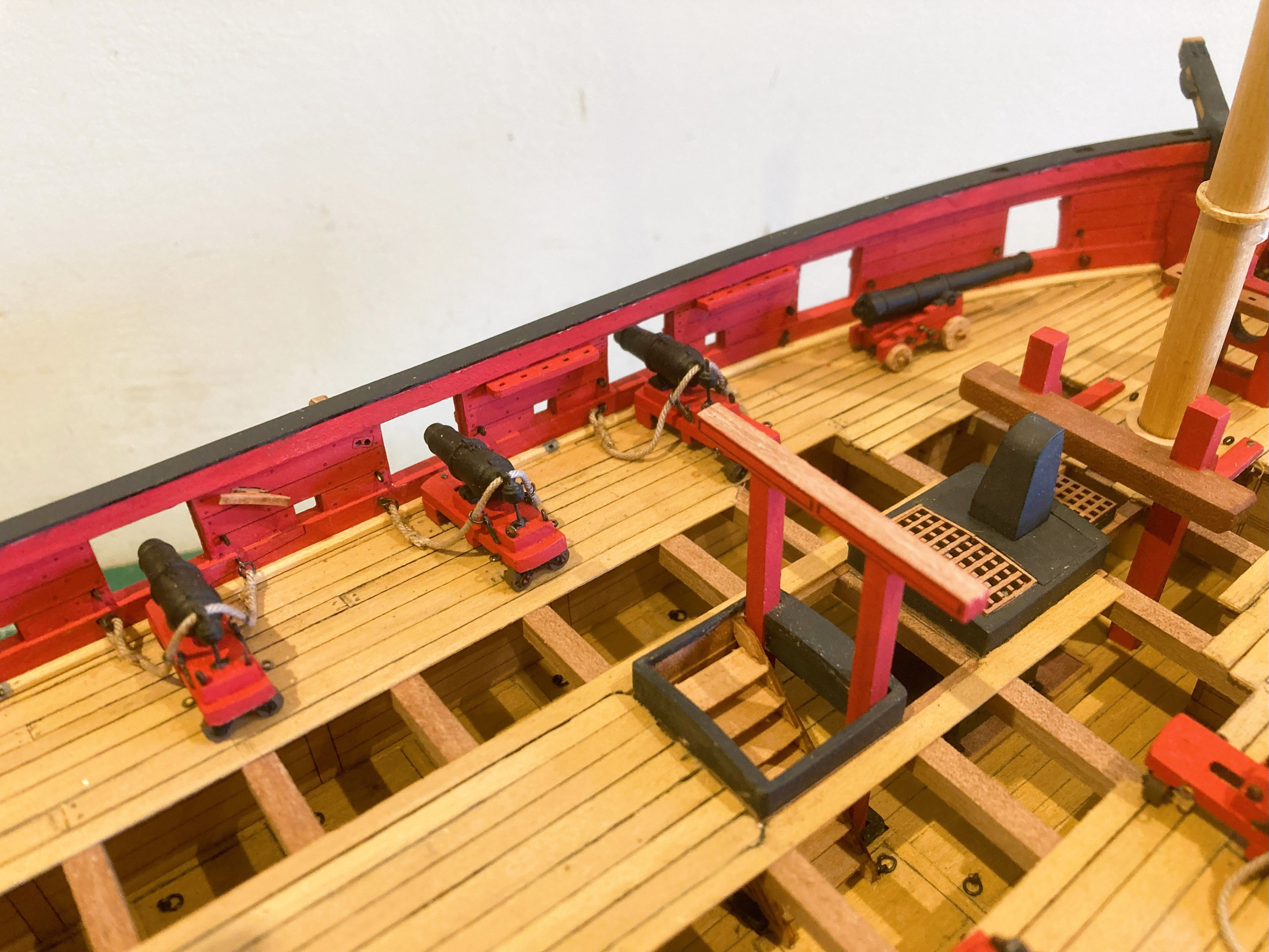
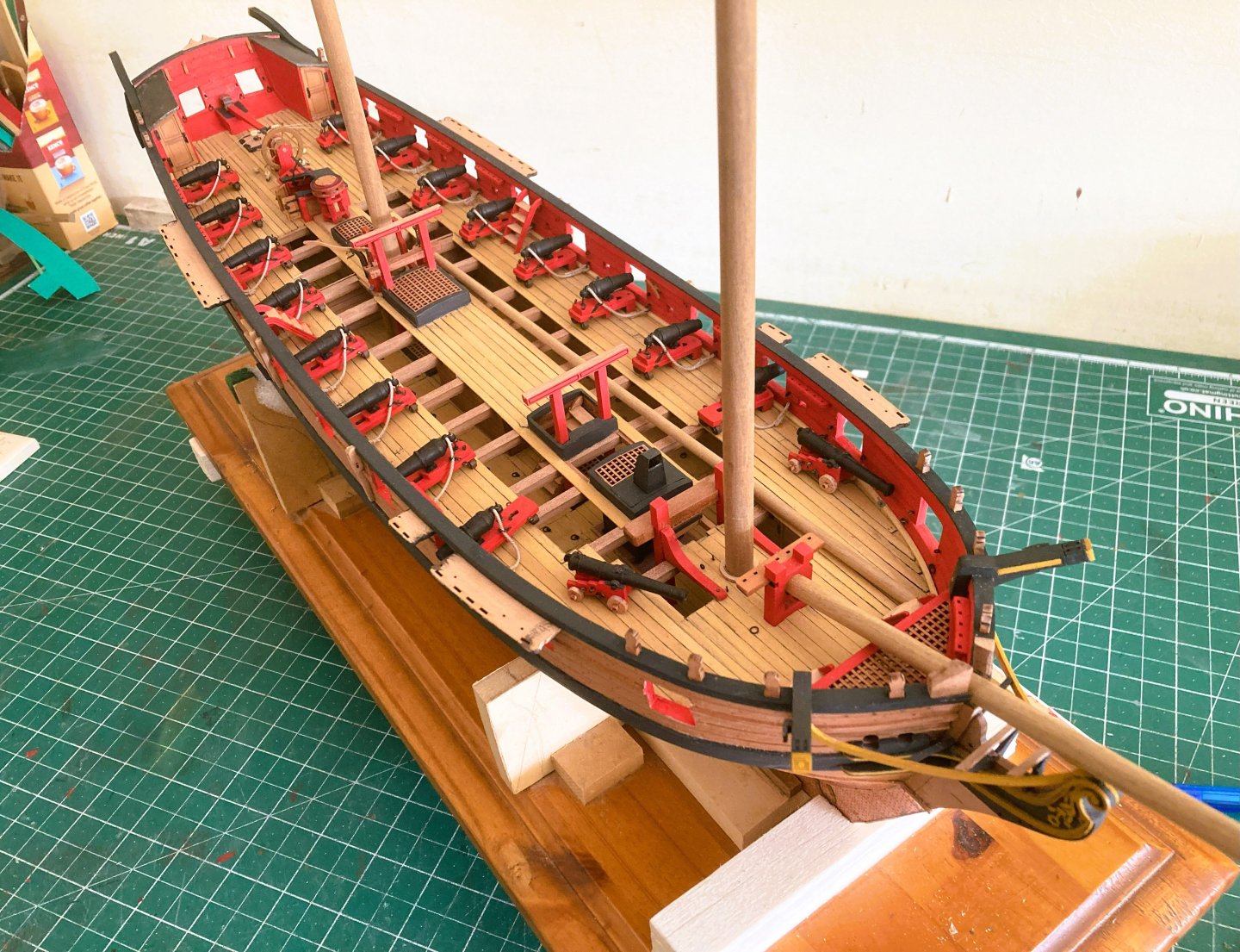
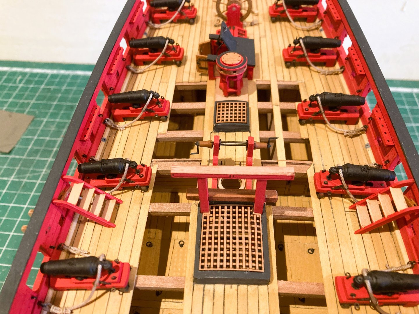
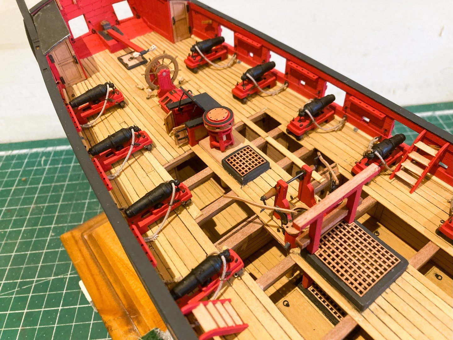
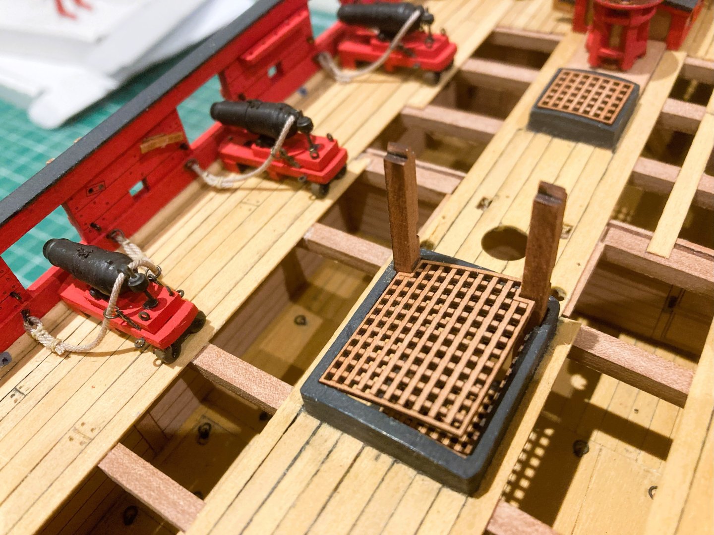
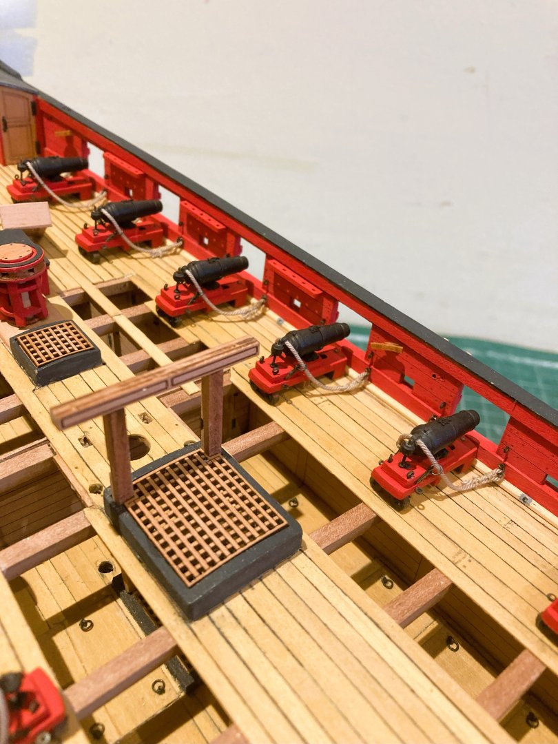
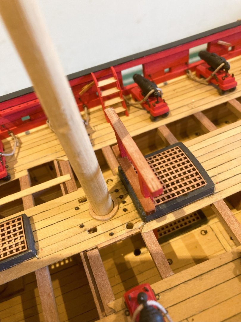
Post 68 Deck fittings. The Gallows There are two sets to make up, and the main consideration is getting them to fit cleanly and squarely thro’ ladderway and Main hatchway, to slot into the lower deck. A little fine tweaking in the area of the coamings was necessary to get a smooth but firm fixture. The aft Gallows pass thro’ the Main Hatch and the provided gratings have a cut-out to pass between the Gallow standards. 3968a Mine did not easily fit, but I was aware that any pressure on the grating and it would surely snap, leaving a tricky repair job, or having to contact Chris to buy a replacement. 3969a By degrees I sanded both standard and access mortise until I could slip the grating into place without stress. It is a large grating which in reality was probably in two or three sections. I did think of modifying it as I did with both Sphinx and Indy, but I got the yips, and couldn’t face bothering Chris yet again……… Sorry Chris, I’ve messed up another grating with my interminable fiddling.🫤 3982a Fore Gallows installed, the Riding Bitts have also been installed at this point. 3976a Gallows completed. 3974a There are a lot of deck eyes to fit, and this is a good point to add the mast coat ring for the masts. Steering Before the wheel is glued into place I considered the complicated arrangement of pulleys that run between tiller and wheel barrel. 3986a I used a pattern from the plans to check the location of the deck blocks, those using the pre-made deck will have those positions already marked. The last time I rigged one of these was on Pegasus a ship built some 20 years previous to Harpy. The only difference in the rig seems to be that foot blocks are used to direct the line from the barrel downwards directly to the deck. The tackles still run across the deck which must have created a serious inconvenience. 3990a I think it is probably best to attach the deck blocks before installing the wheel to give the best chance of making a neat job of seizing the blocks to the deck eyes. I am using Syren 3mm Boxwood blocks in preference to the basic kit version. The blocks are seized to the rings before fitting. 3988a 3995a 3992a The tiller lines will be rigged later, still more things to do on the deck. B.E. 23/04/2025


- 332 replies
-
- 24
-
-
- Harpy
- Vanguard Models
- (and 1 more)
-
Very nice build Doug, well done. 👍 The Vanguard range of fishing boats make such fine attractive models that don't need cases, they are easy to keep clean, and don't take up much room. I love the two I built and there is another beneath the bench. B.E.
-
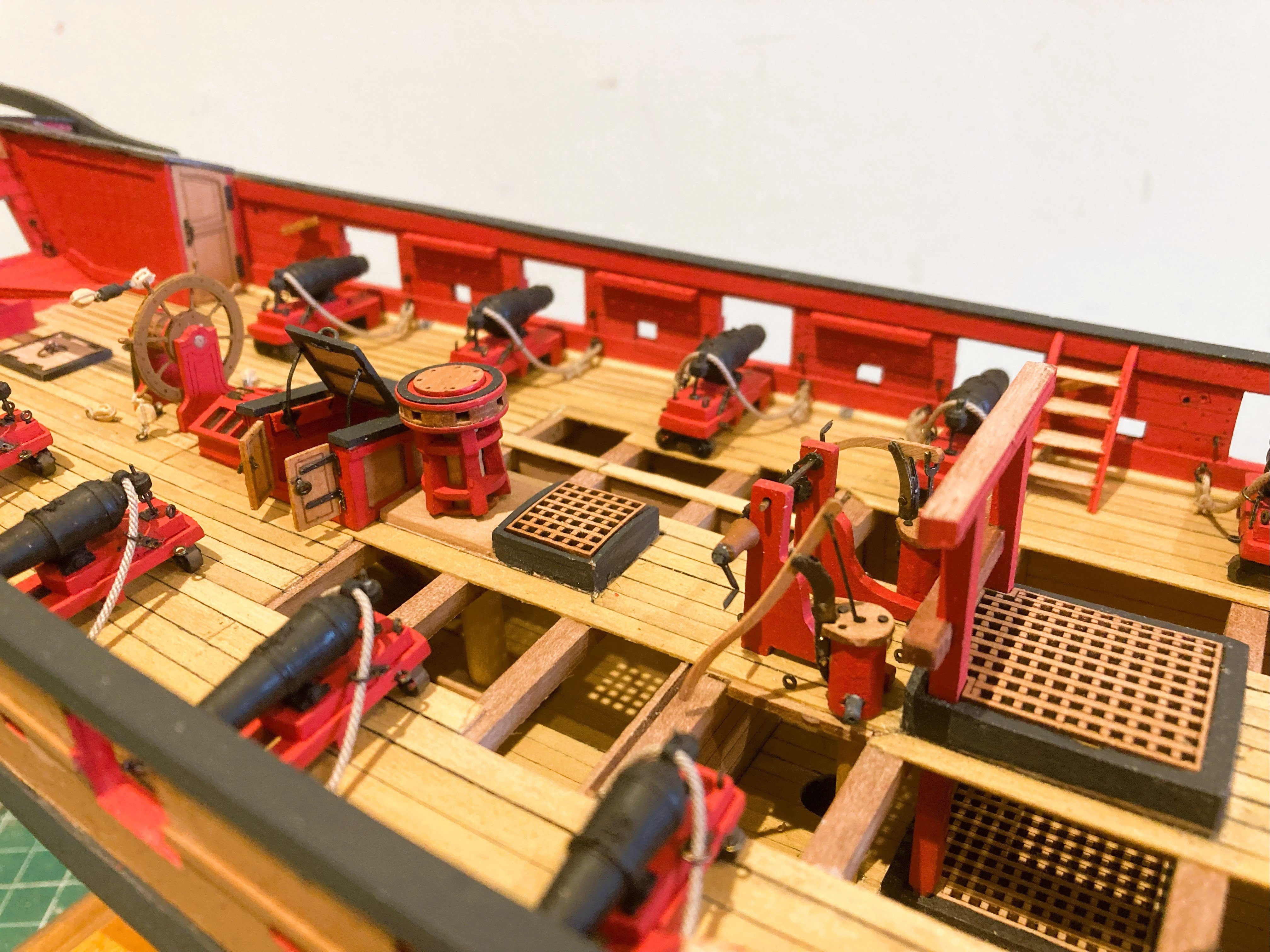
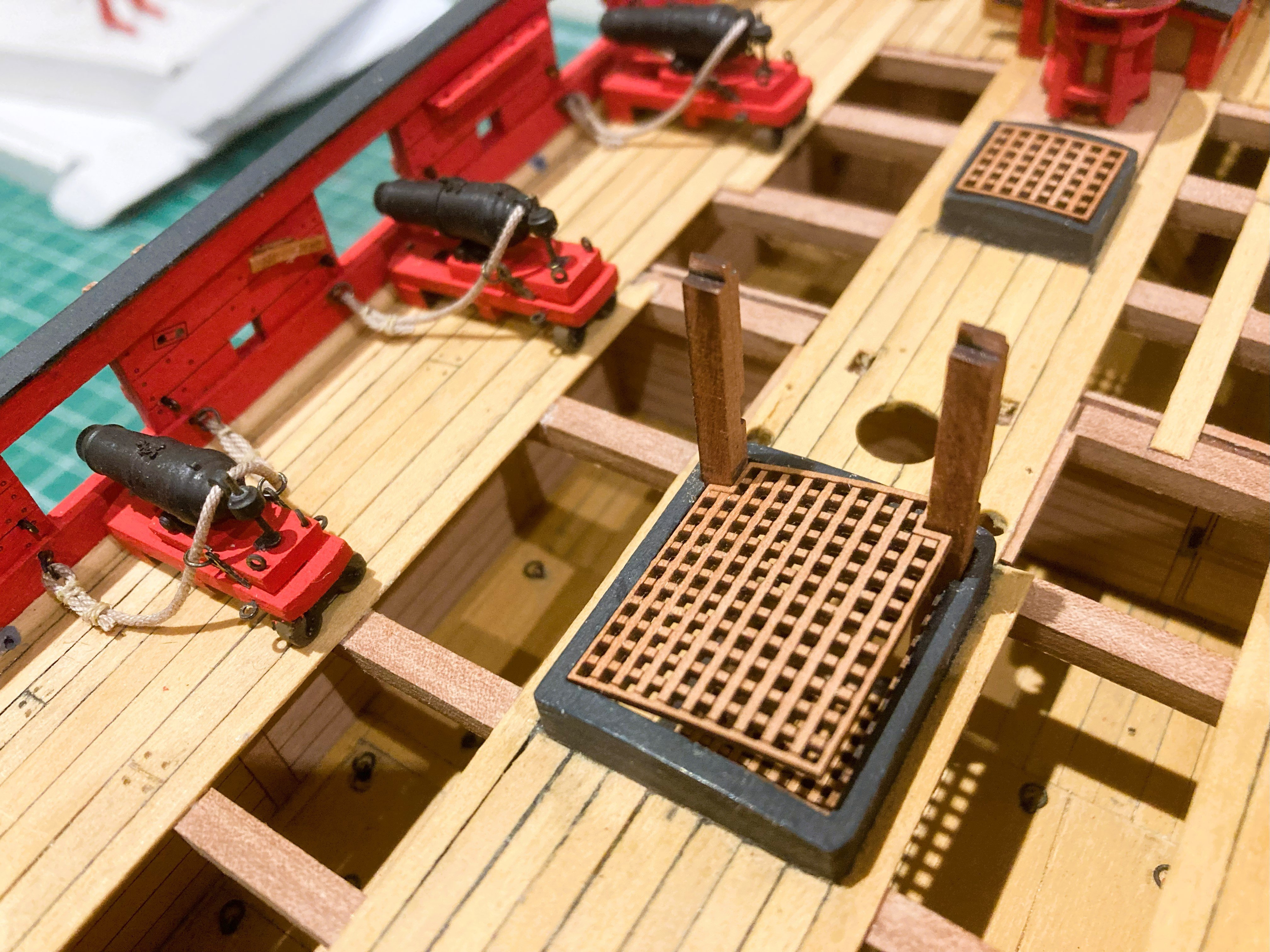
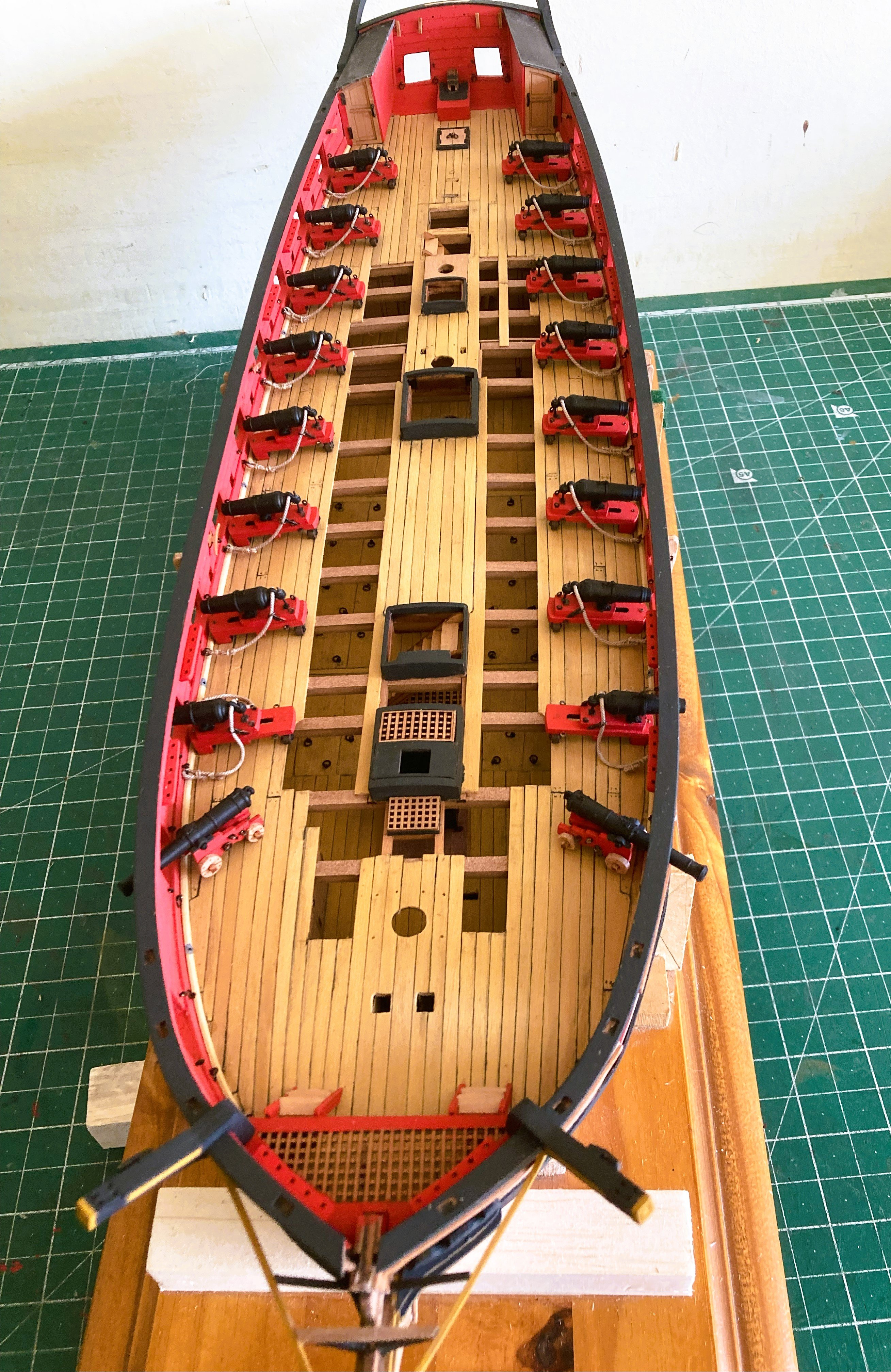
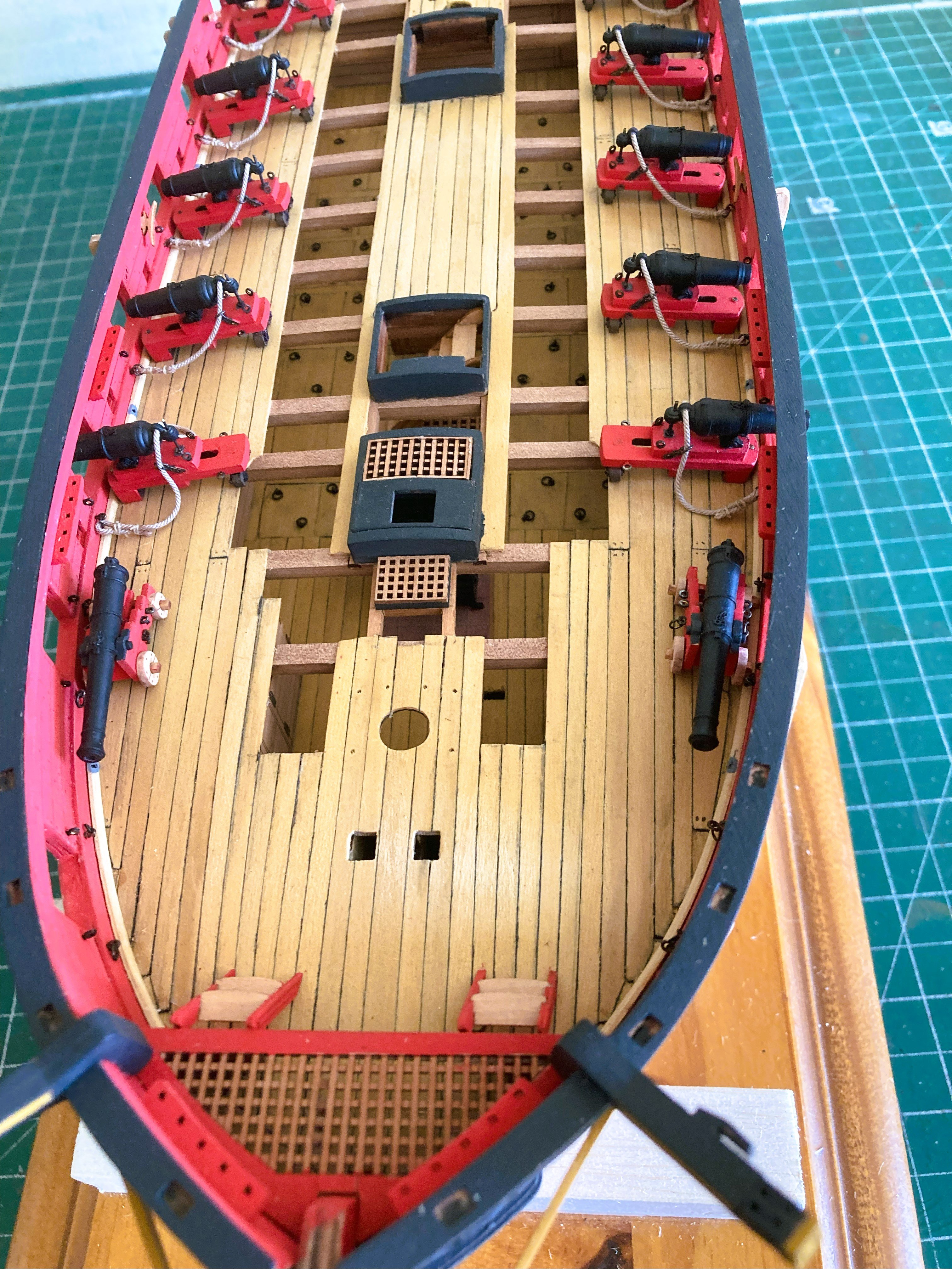
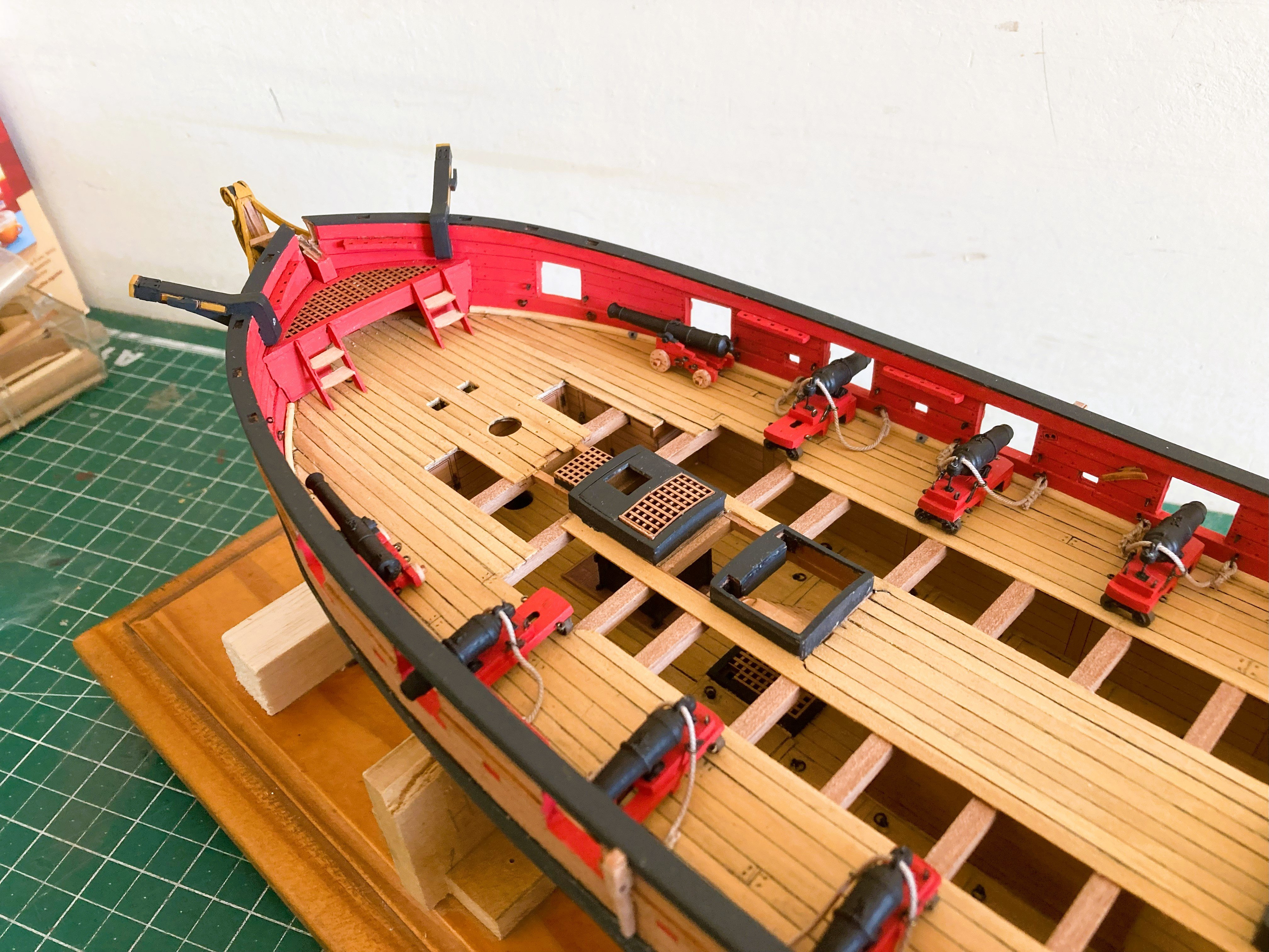
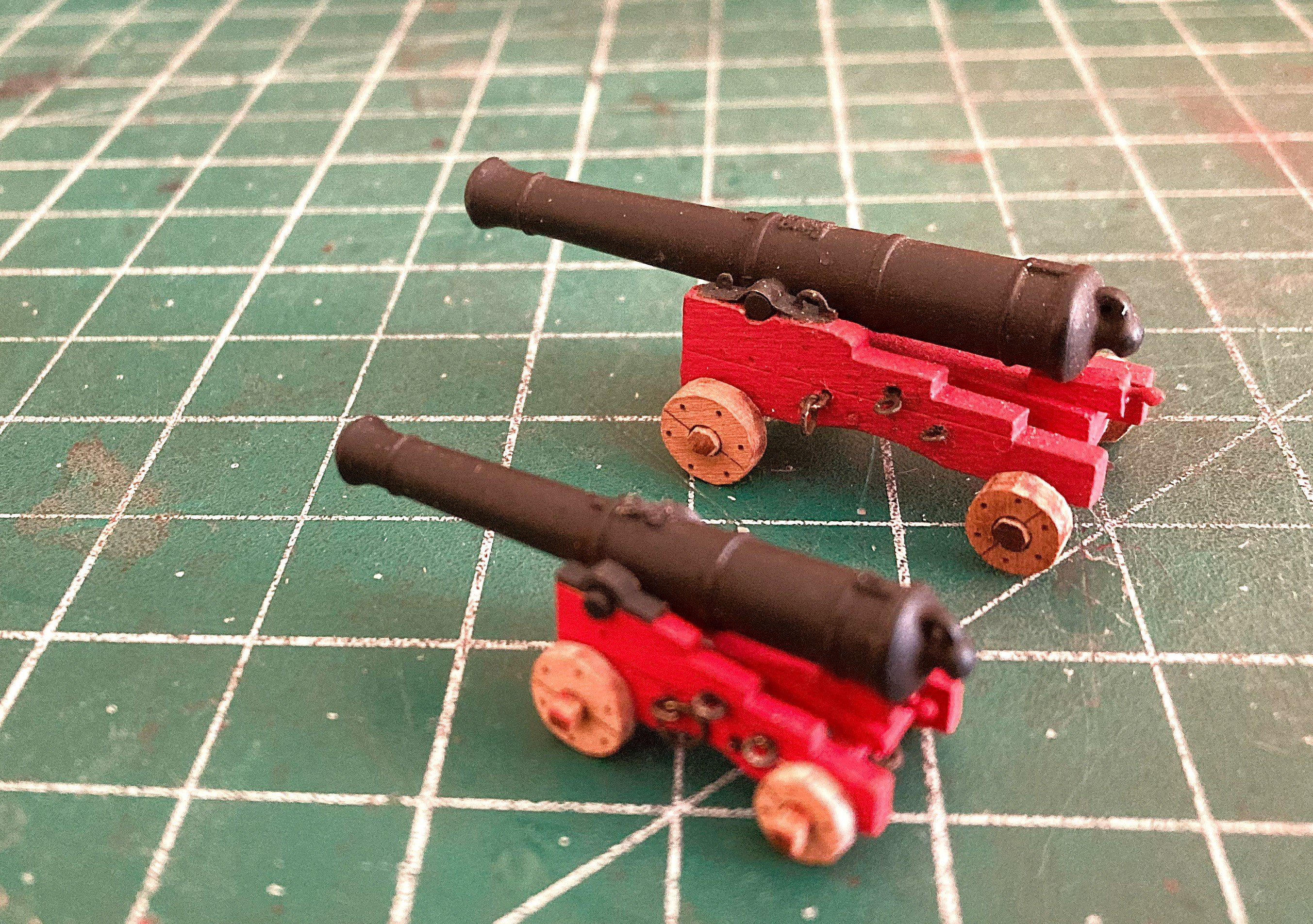
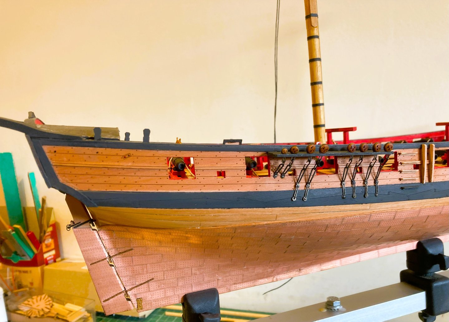
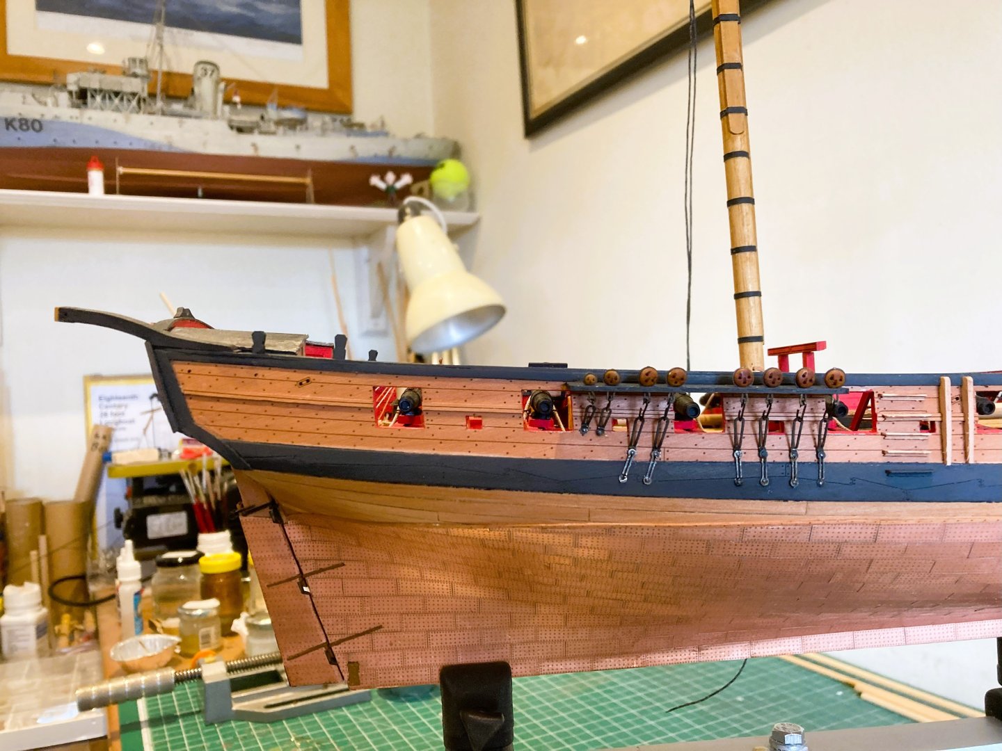
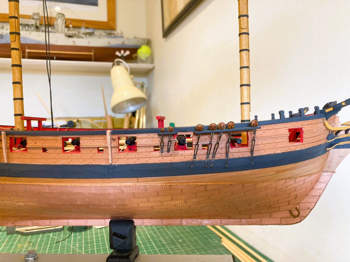
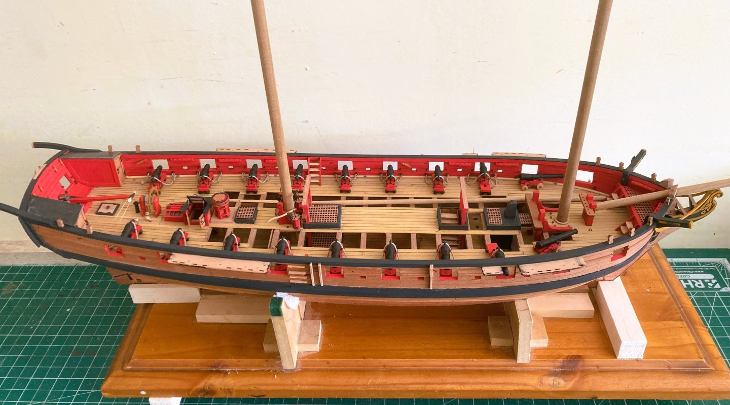
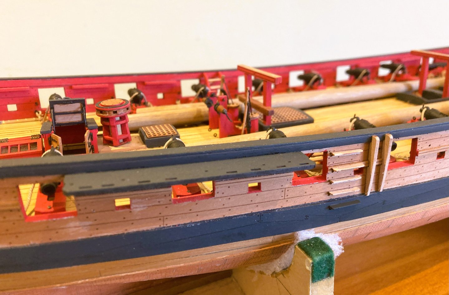
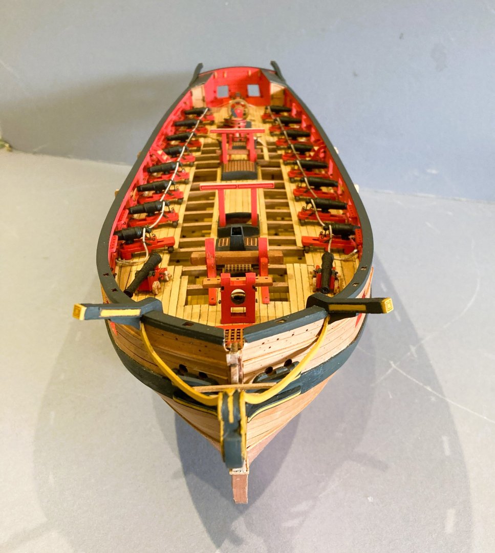
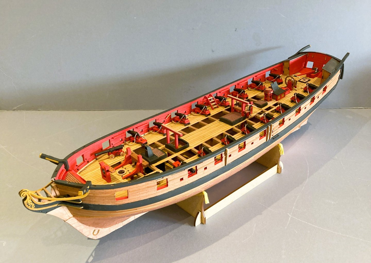
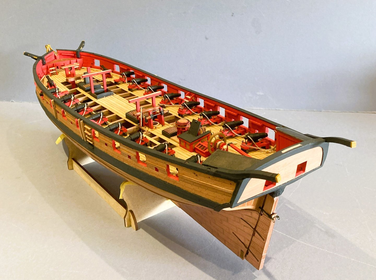
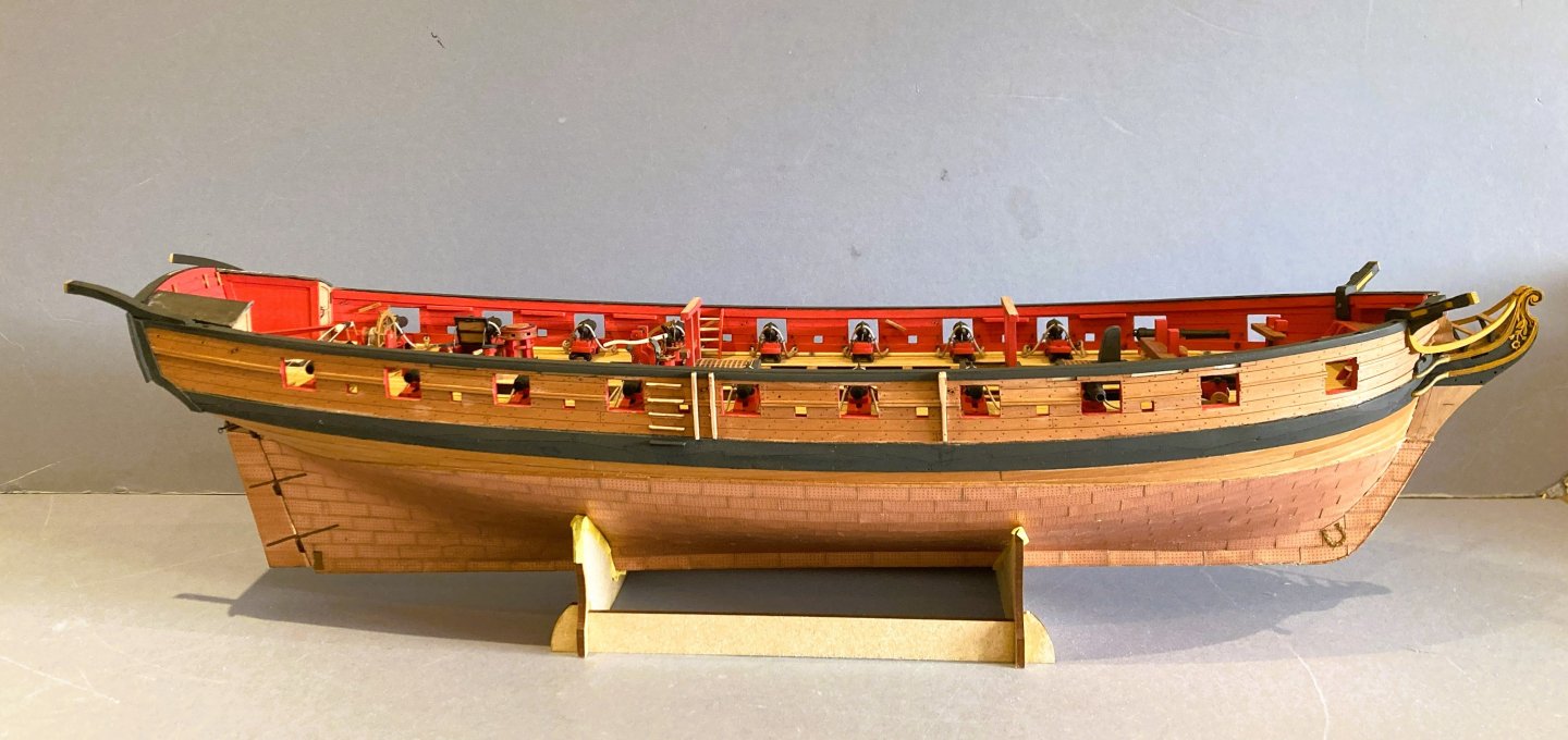
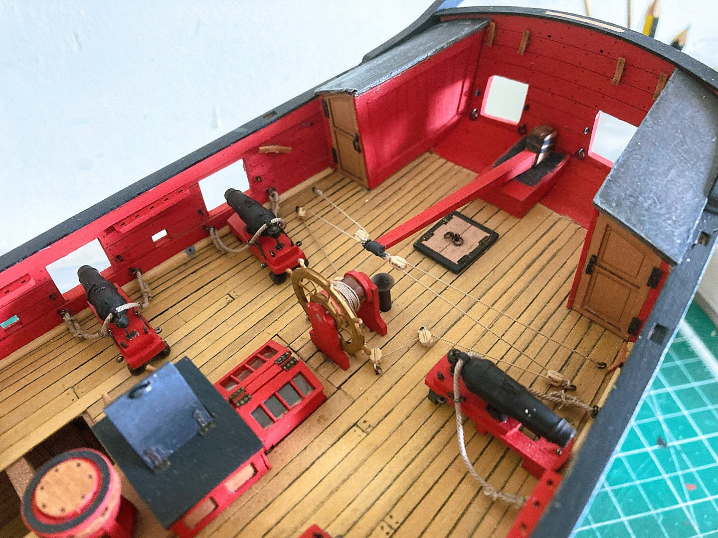
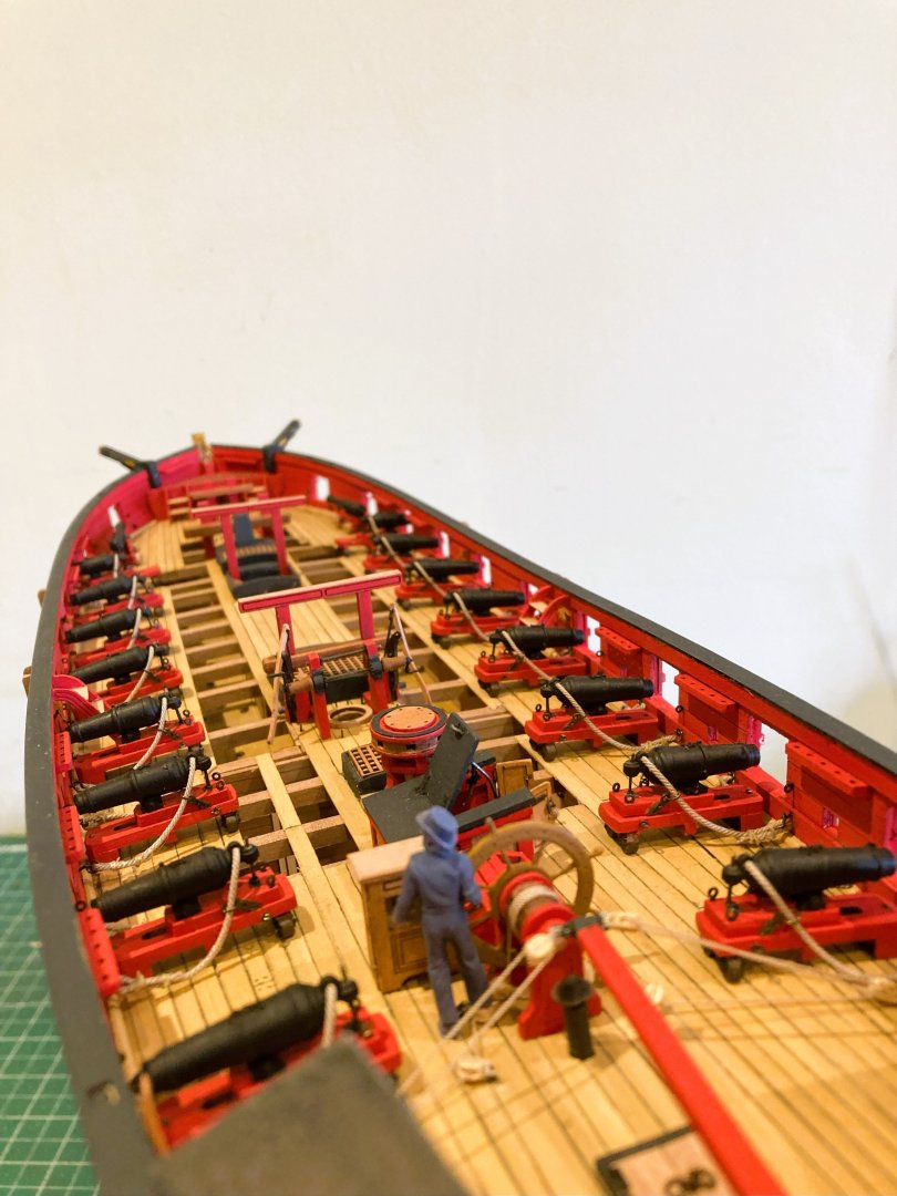
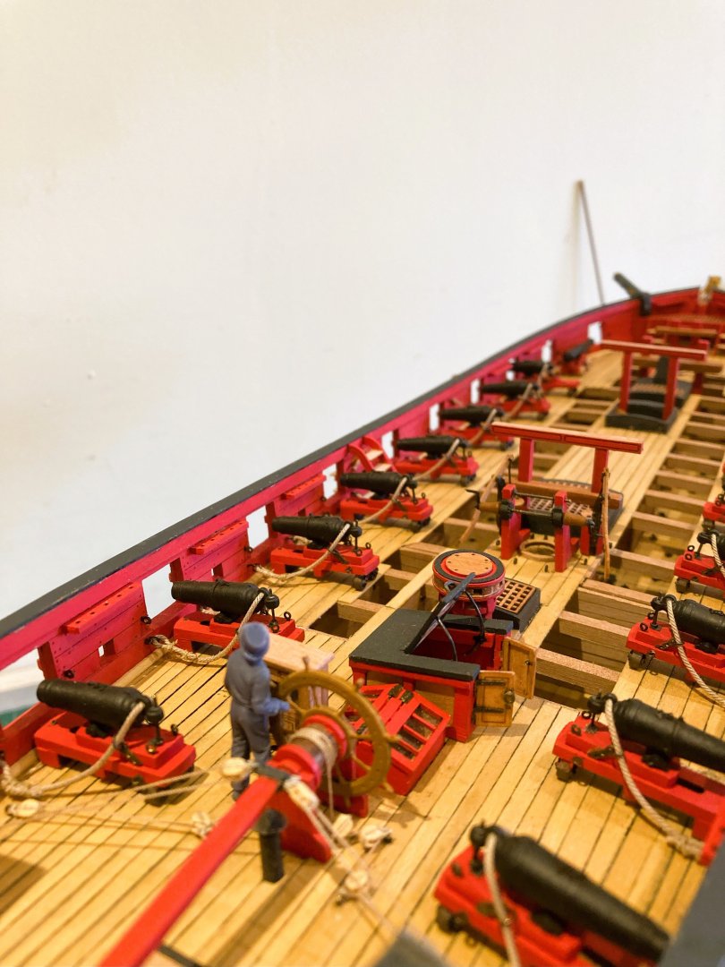
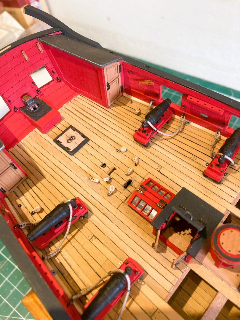
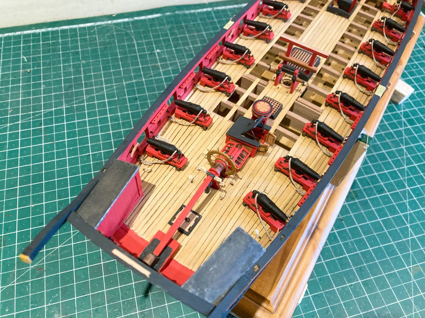
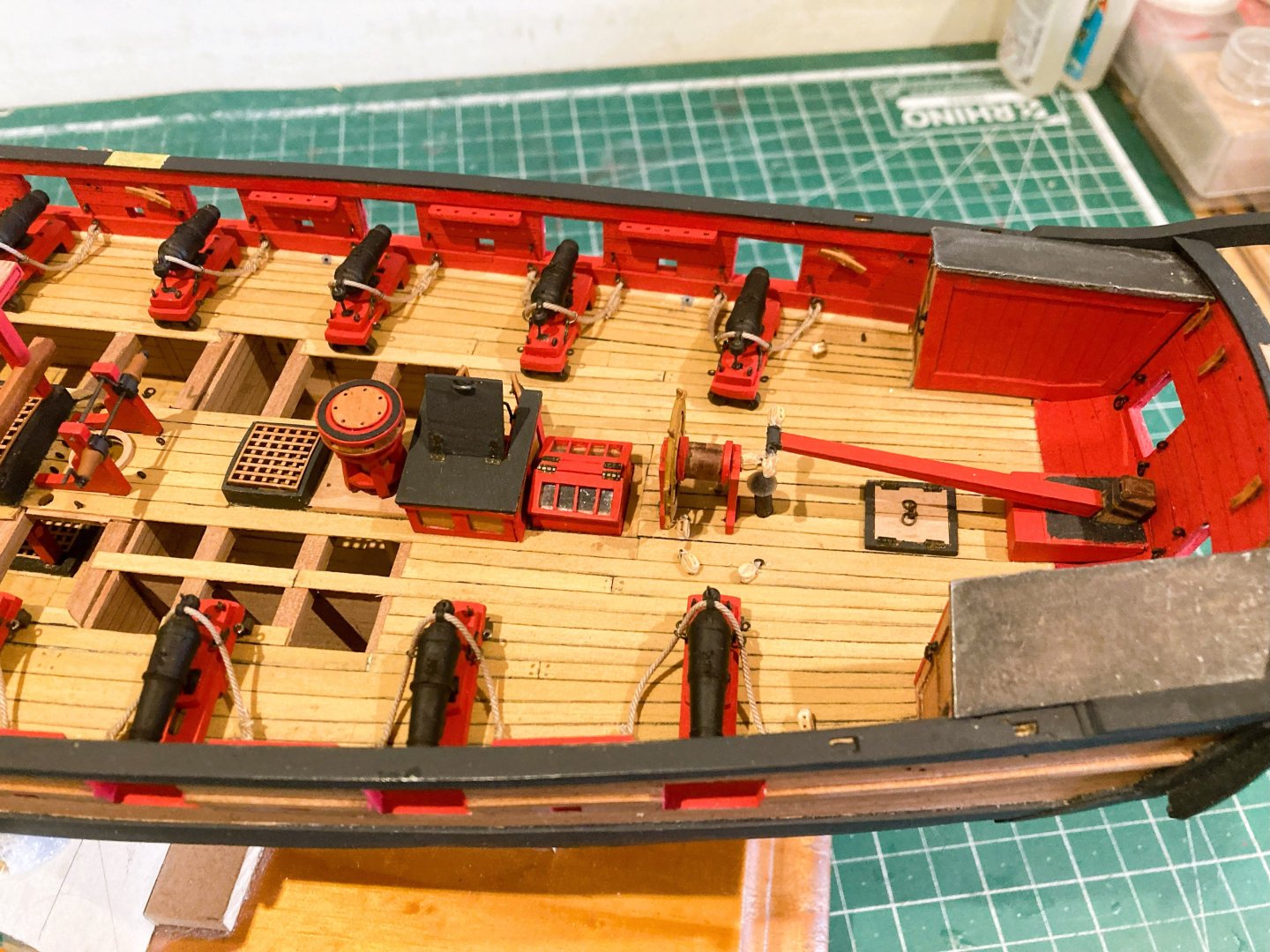
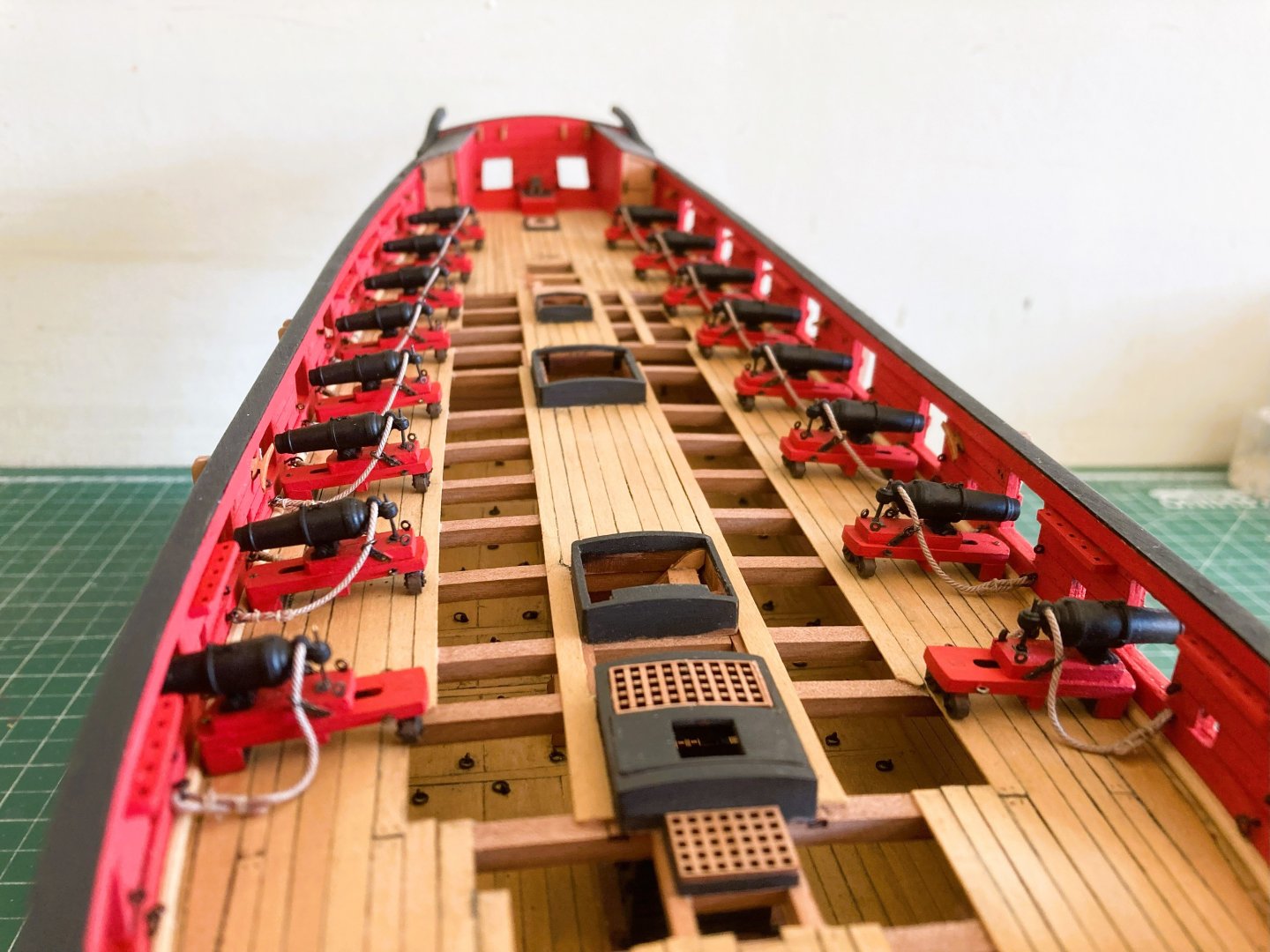
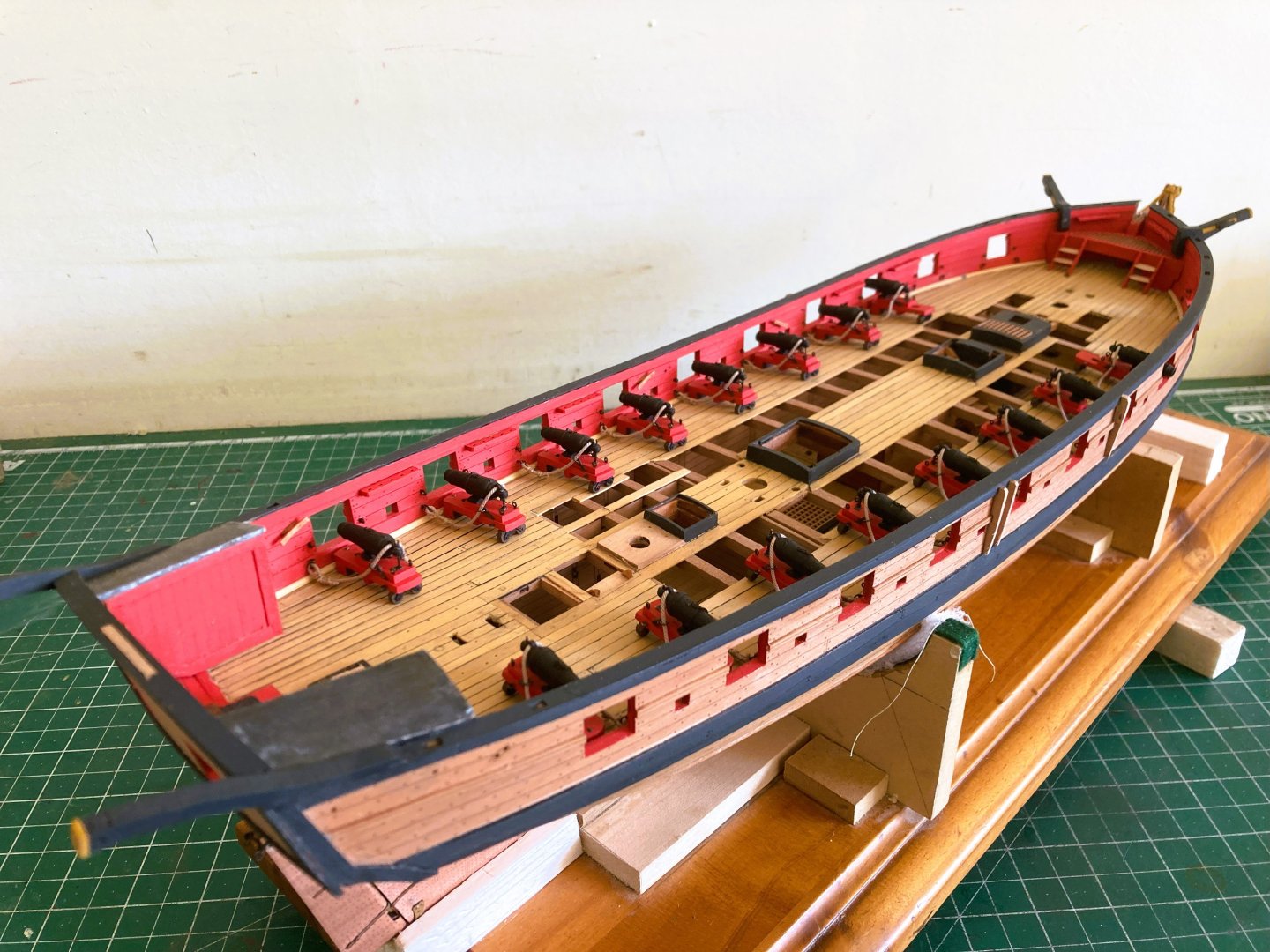
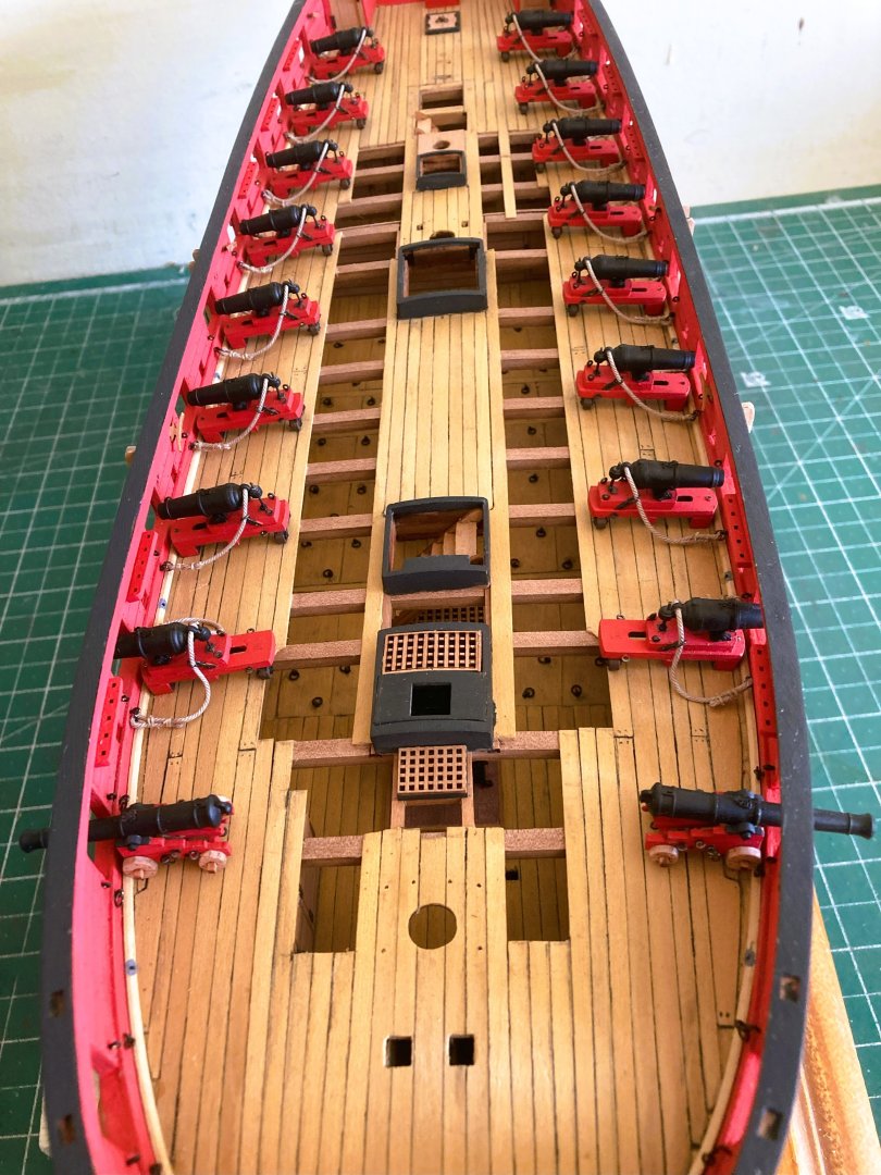
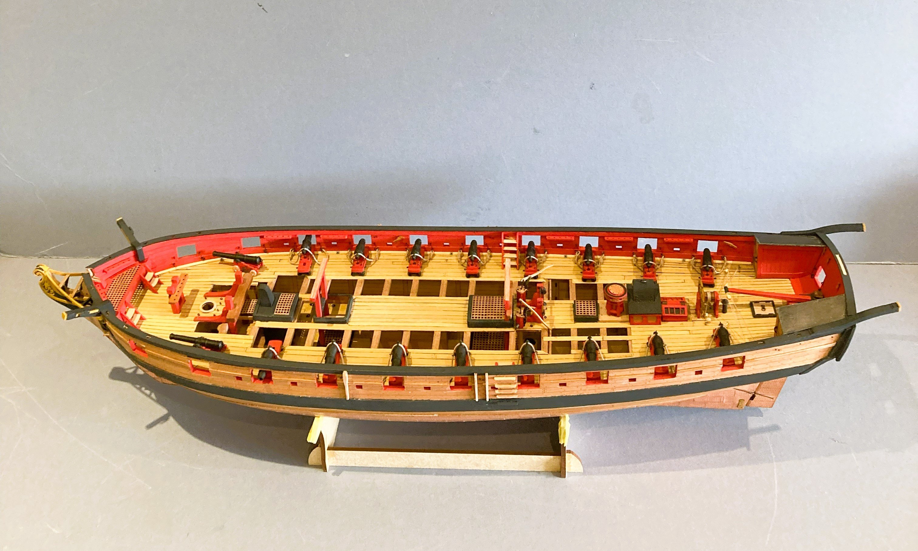
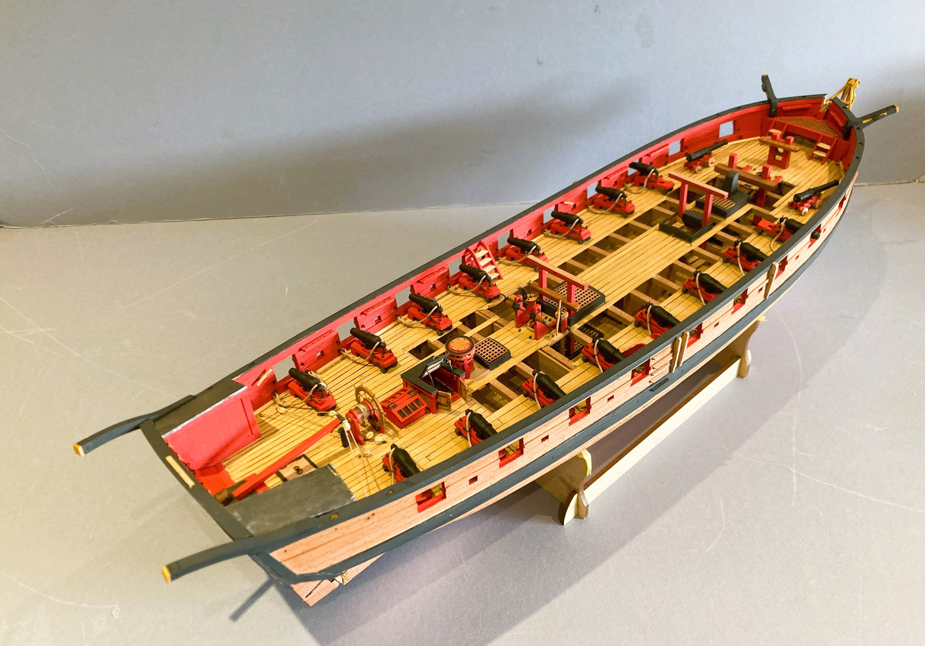
Post 67 Carronade installation completed. 3946a The port side installations went a little quicker than the starboard, but still took a full day. 3949a An impressive set of teeth has Harpy. Note the extra slackness of breeching line on the forward run-out carronades. It is a common error to show the lines too tight, which would not allow for recoil. 3954a Then there are the Long guns…. 3967a The six pounders are quite small, here compared to the 12 pounder chasers on Indy. I am a bit undecided how to display the long guns aboard Harpy. 3957a With the guns run-out, those long barrels protruding rather destroys the otherwise symmetry of the broadside. The effect would be reduced somewhat once the Channels are in place. 3958a I could angle the bow chasers but that doesn’t hold a great appeal to me. 3959a An alternative would be to secure alongside. This keeps the guns inboard and does have symmetry that appeals. 3963a This arrangement, frees up space around the crowded area of the Foremast, Riding bitts, and Bowsprit step, as well as showing a different way to secure the guns. I’ll ponder a while before deciding but I now have the pleasure of installing all those deck fittings made earlier. B.E. 21/04/2025


- 332 replies
-
- 25
-
-
- Harpy
- Vanguard Models
- (and 1 more)
-
A beautiful build of Cheerful, well done Erik.👏 B.E.
-
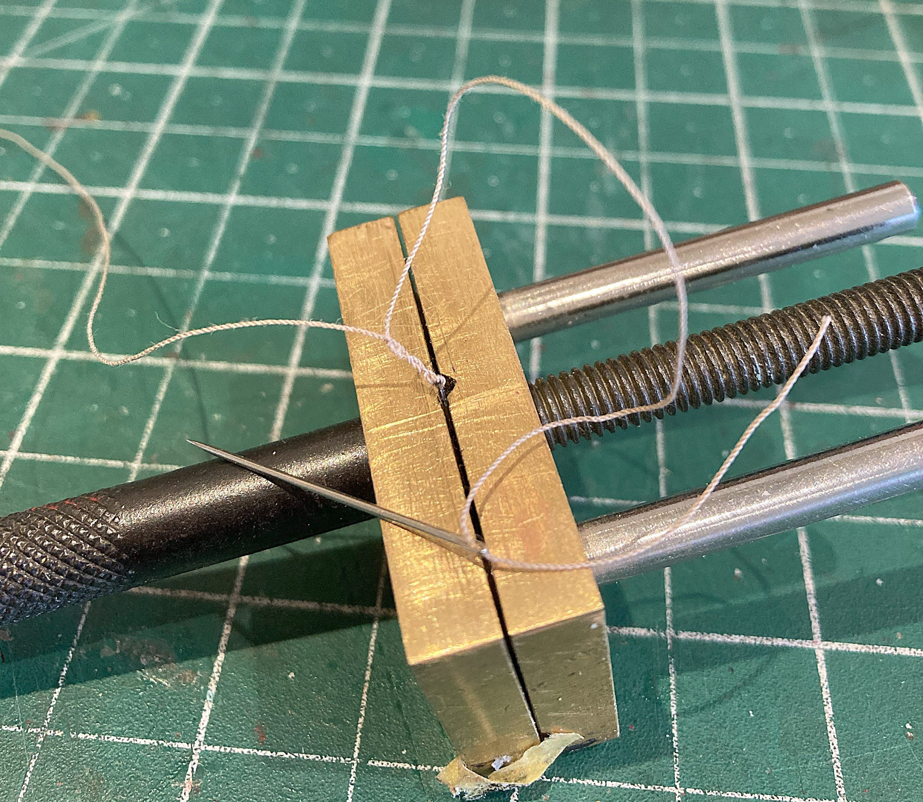
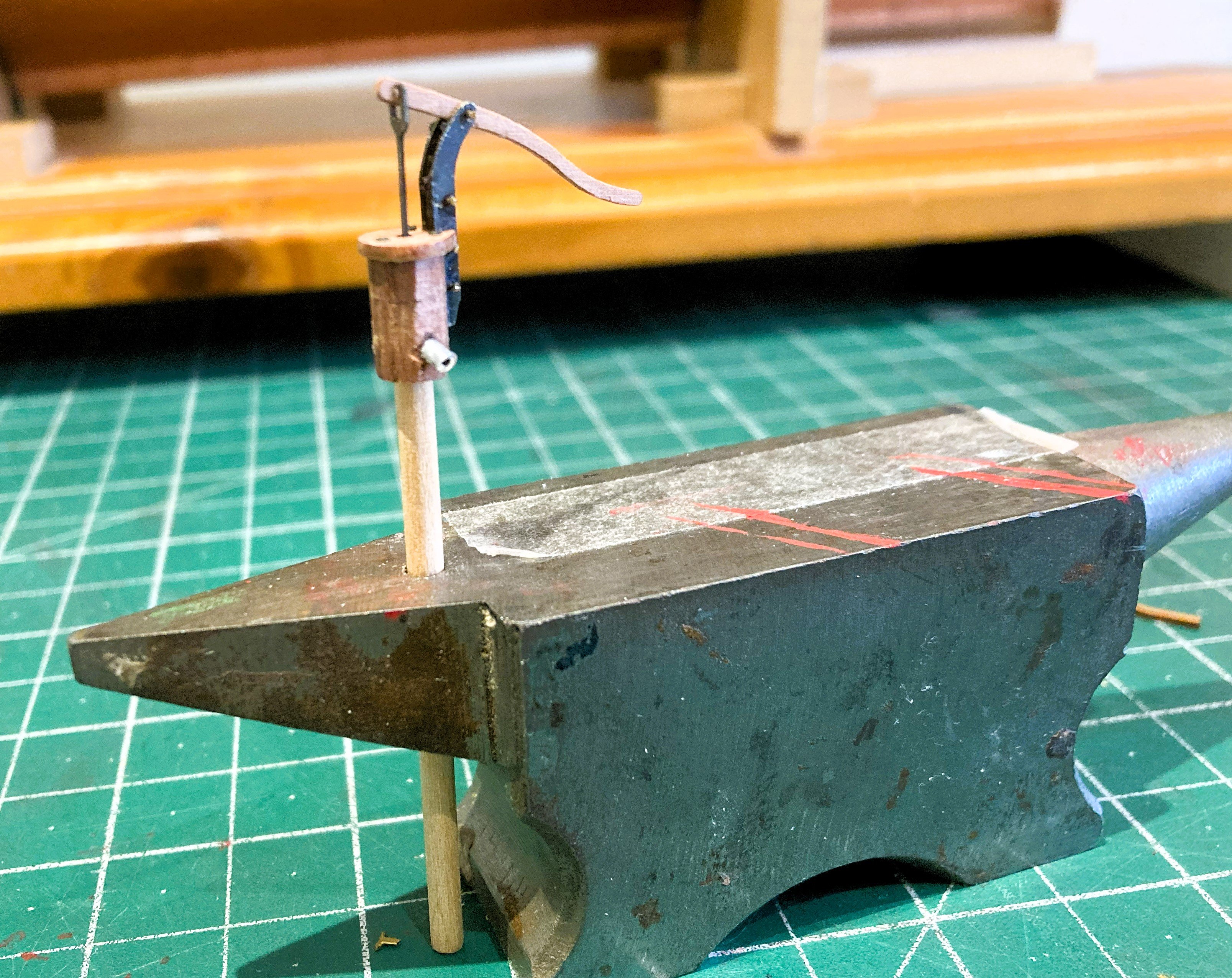
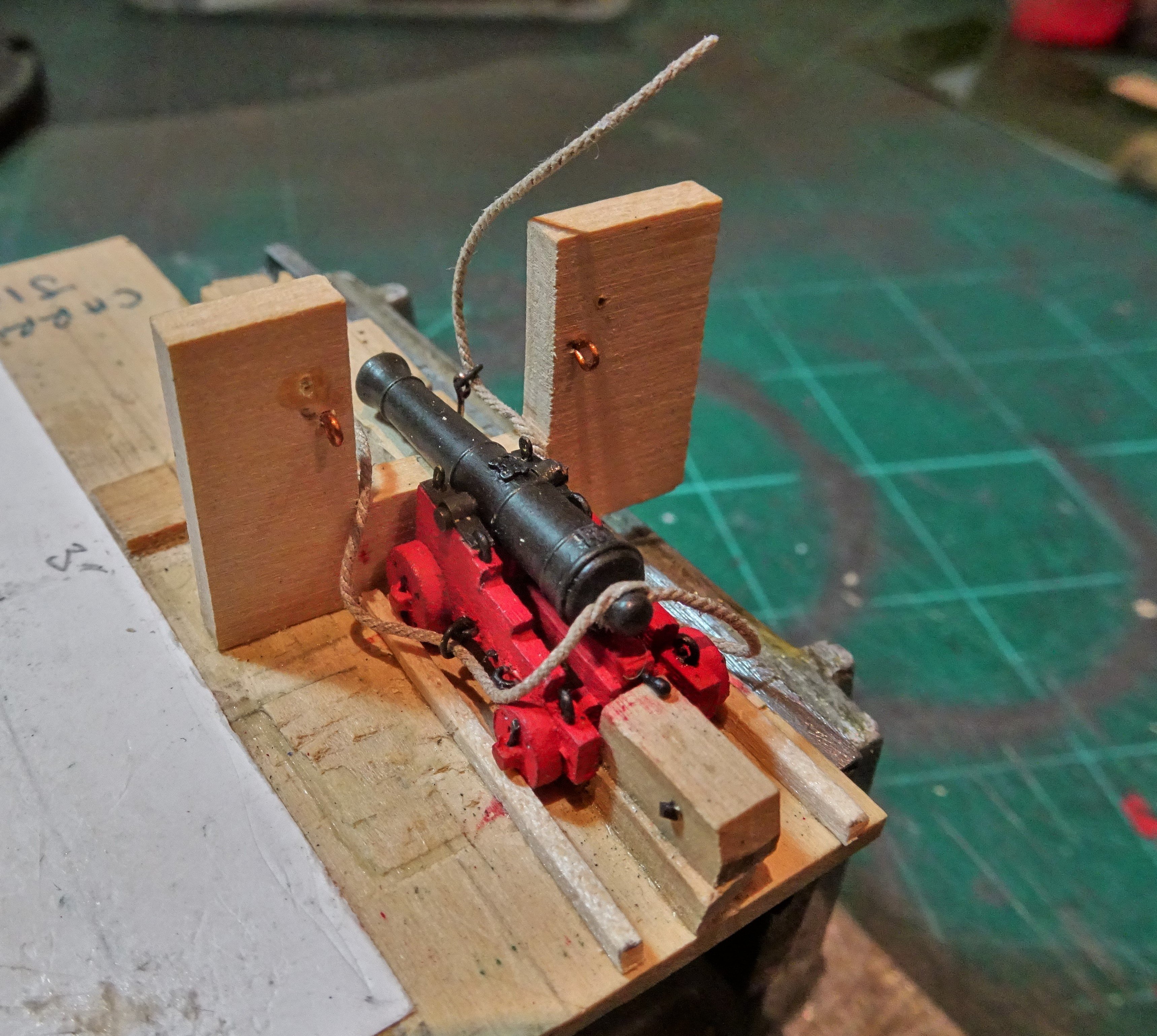
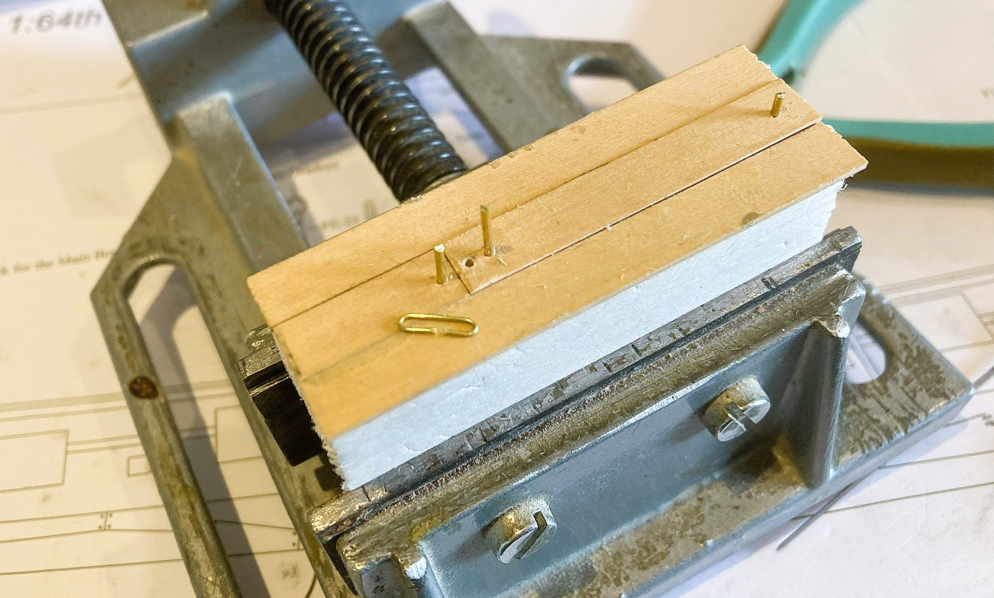
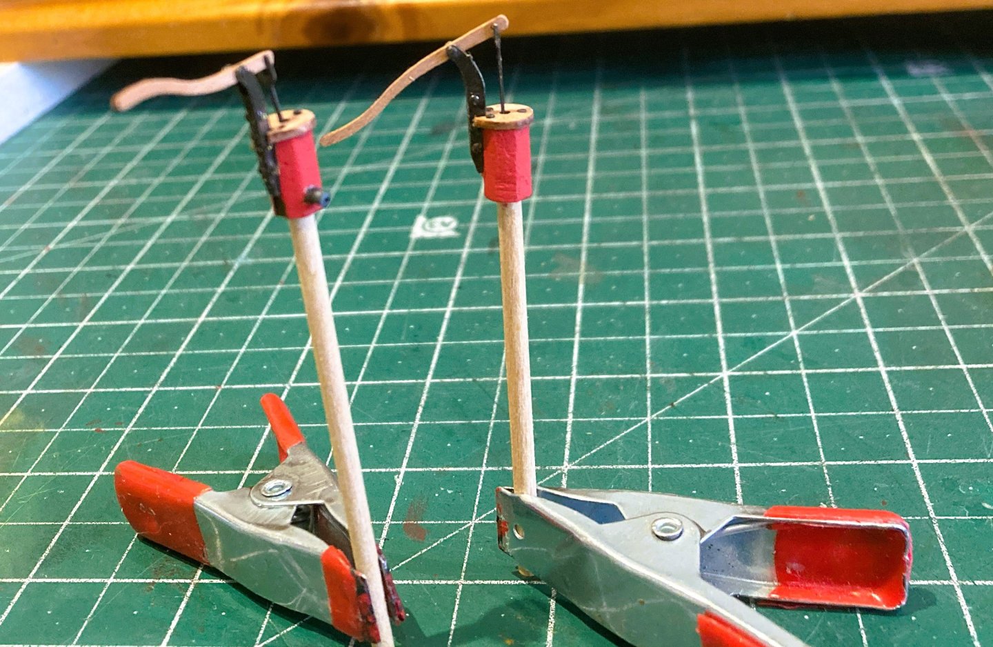
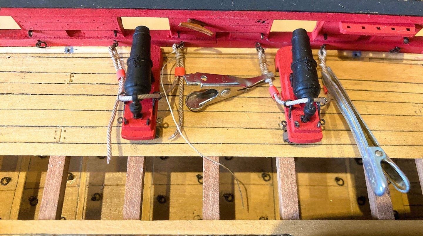
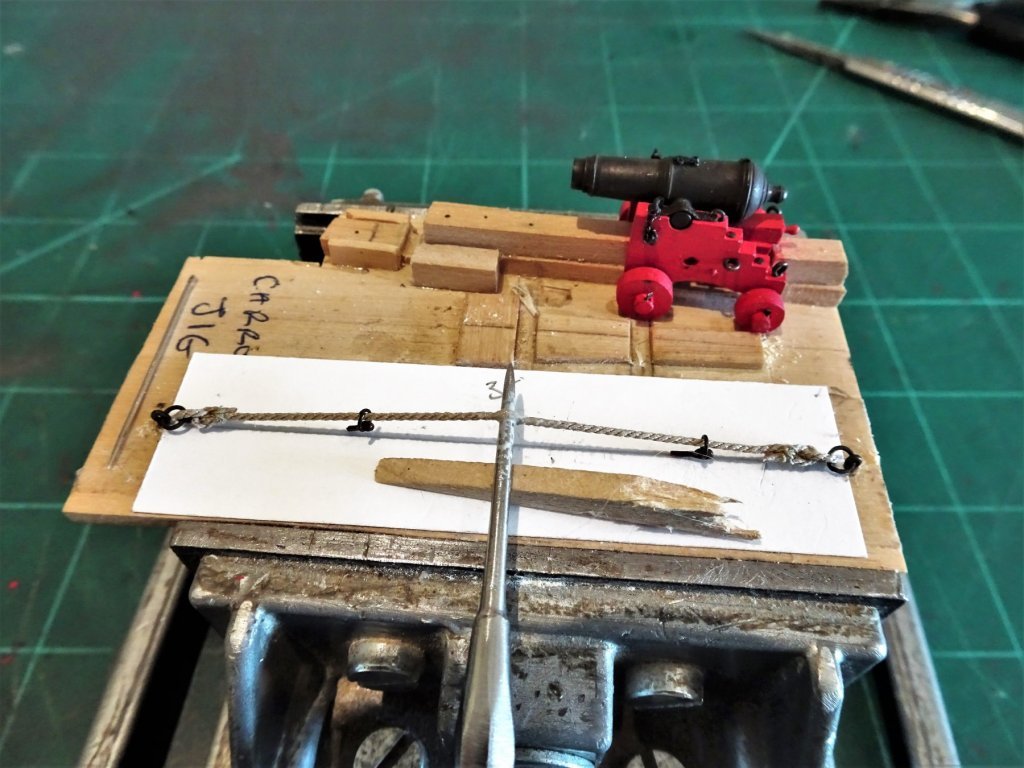
Cheers Daniel, the sleeve system works well in this situation.👍 @ Dave, - You're right of course but I had glued the bulwark fittings before I decided to rig the Breeching lines. Originally I had intended to leave them unrigged as with Sphinx and Indy. Navy Board style. Fitting the rings was in itself a tedious business and I had no desire to try and remove them at this stage. Jigs are an excellent way to reduce the pain of gun rigging. As used on the Cutter Alert. - also used to rig the side tackles. As used on the Cutter Cheerful. On the model rigging is penance for my change of mind. 🫤 Cheers, Maurice. (B.E.)
.thumb.JPG.d43701b79ba5e34376ef8474bc5bc823.jpg.2a90738ce8a010ffea1dd7f56feb98f6.jpg)

- 332 replies
-
- 14
-
-
- Harpy
- Vanguard Models
- (and 1 more)


.JPG.efd3cb1b4745d495f77447e85990d57b.JPG)