.JPG.ca33079f5815b861e67b9c2cccd37982.JPG)

Blue Ensign
-
Posts
4,569 -
Joined
-
Last visited
Content Type
Profiles
Forums
Gallery
Events
Everything posted by Blue Ensign
-
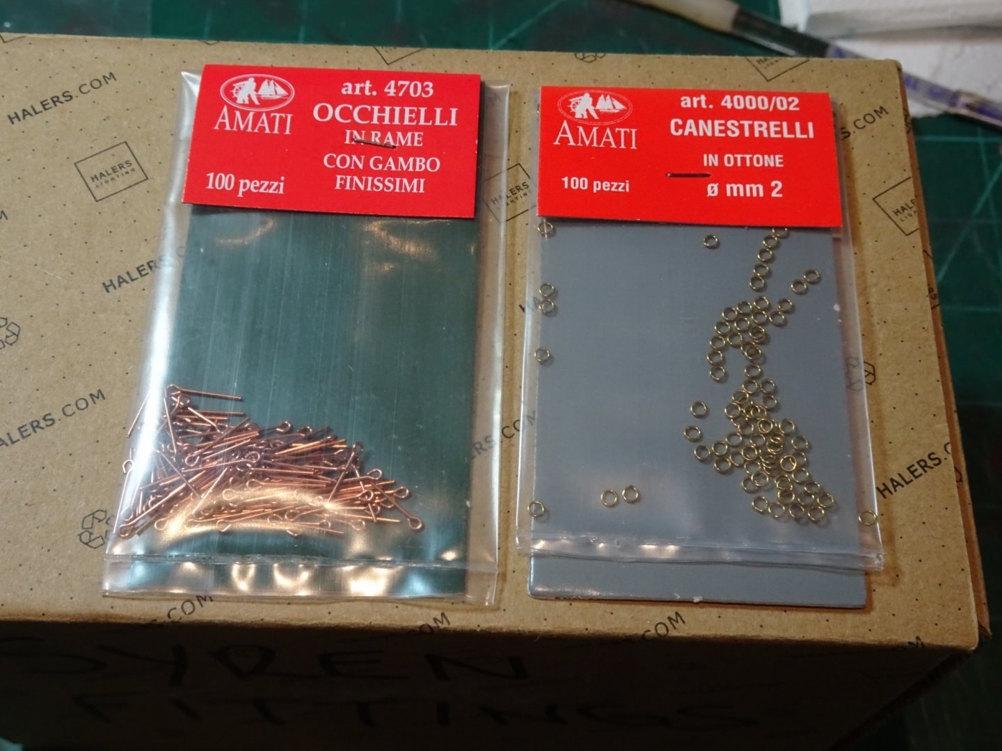
 Hi Jacek, These are the measurements applicable to 9 pounder guns. The Breeching rope is 4½" circumference equating to 0.56mm ø at scale. I will be using Syren 0.63mm line for the purpose. The Breeching ring is 3” in the clear = 1.19mm. The ring thickness is ⅞”ø = 0.34mm at scale. The Amati 2mm rings are close to these dimensions. The loops are ½”ø thick, (0.19mm) and 1½” in the clear (0.59mm) The Amati eyebolts are close enough for scale, but need a slight tweak to make them loops rather than eyes. These figures are taken from The FFM, David Antscherl, and The Arming and Fitting of English ships of War, Brian Lavery. Chris is not a great fan of rigging guns, but the manual does provide details of blocks and line sizes. If following the manual advice I would go for the larger 0.75mm ø line to provide a nice contrast with the 0.1mm tackle lines. The provided carriage eyebolts are too thick, and are flat rather than rounded, as a result of the etching process. In reality this matters little in the overall scheme of things, very little will be seen of the gun detail once the Gangboards are in place, but the pedant in me drives me on.🙄 Hope this helps. B.E.
- 857 replies
-
- 4
-

-
- Sphinx
- Vanguard Models
- (and 1 more)
-
Blimey Glenn, I expect to add around £100 in additional stuff for my build but I think you'll hold the record for the most expensive Sphinx build on MSW. B.E.
-
Thanks for your input guys, as a weathering novice it’s all useful stuff. @ Bob – re the wheel axles – it only requires the slightest touch on the corners, I will do it even less on the other guns. @ Thuky – with these particular guns once they are secured between the carriage brackets there is no need to touch them again, or even during fitting. Held on a cocktail stick they can be fitted untouched by human hand, or in Jacek’s case a catspaw. @ Jacek – They don’t look quite as weathered from normal viewing distance but a spot of extra buffing will remove any residual rust. -re the carriage iron work – For the ring bolts I used 2mm eyebolts and 2mm brass rings. The eye of the eyebolt was reduced in size a fraction and closed around the ring. For the loops I use the eyebolts set slightly into the carriage side. As fitted on a Pegasus carriage I also used the same approach for the tackle rings and bolts on the bulwarks. B.E.
- 857 replies
-
- 8
-
-
- Sphinx
- Vanguard Models
- (and 1 more)
-
I'm pretty new to weathering as well, I'm just following Chuck's guidance. I suppose if you prime or paint them first, there's probably no need, perhaps it provides a key to hold the powders, but I just brushed it on dry and off again using a soft brush. Well worth having a go tho'. B.E.
- 857 replies
-
- 5
-
-
- Sphinx
- Vanguard Models
- (and 1 more)
-
Unfortunately not, only up to the waterline. B.E.
-
You could always copper her, the real thing was coppered in 1781.🤔 B.E.
-
Looks like she's casting a critical eye, I hope she likes it. I do, her lines, (the model, not the cat) look elegant, nice job, Jacek. B.E.
-
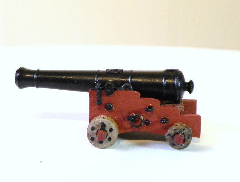
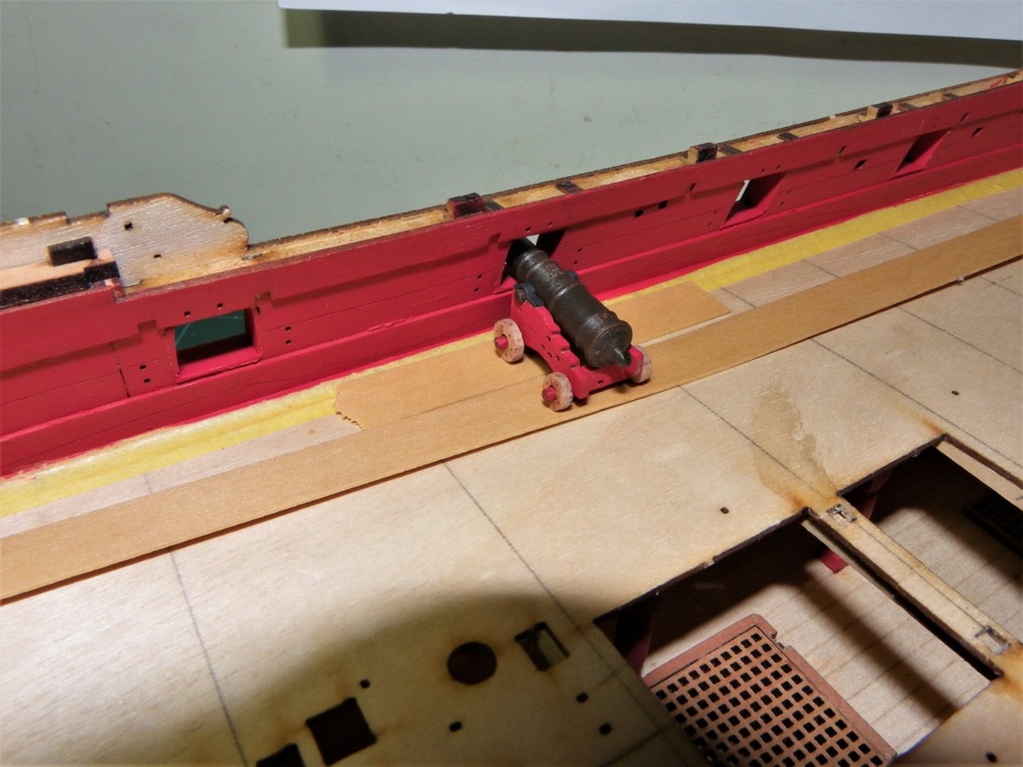
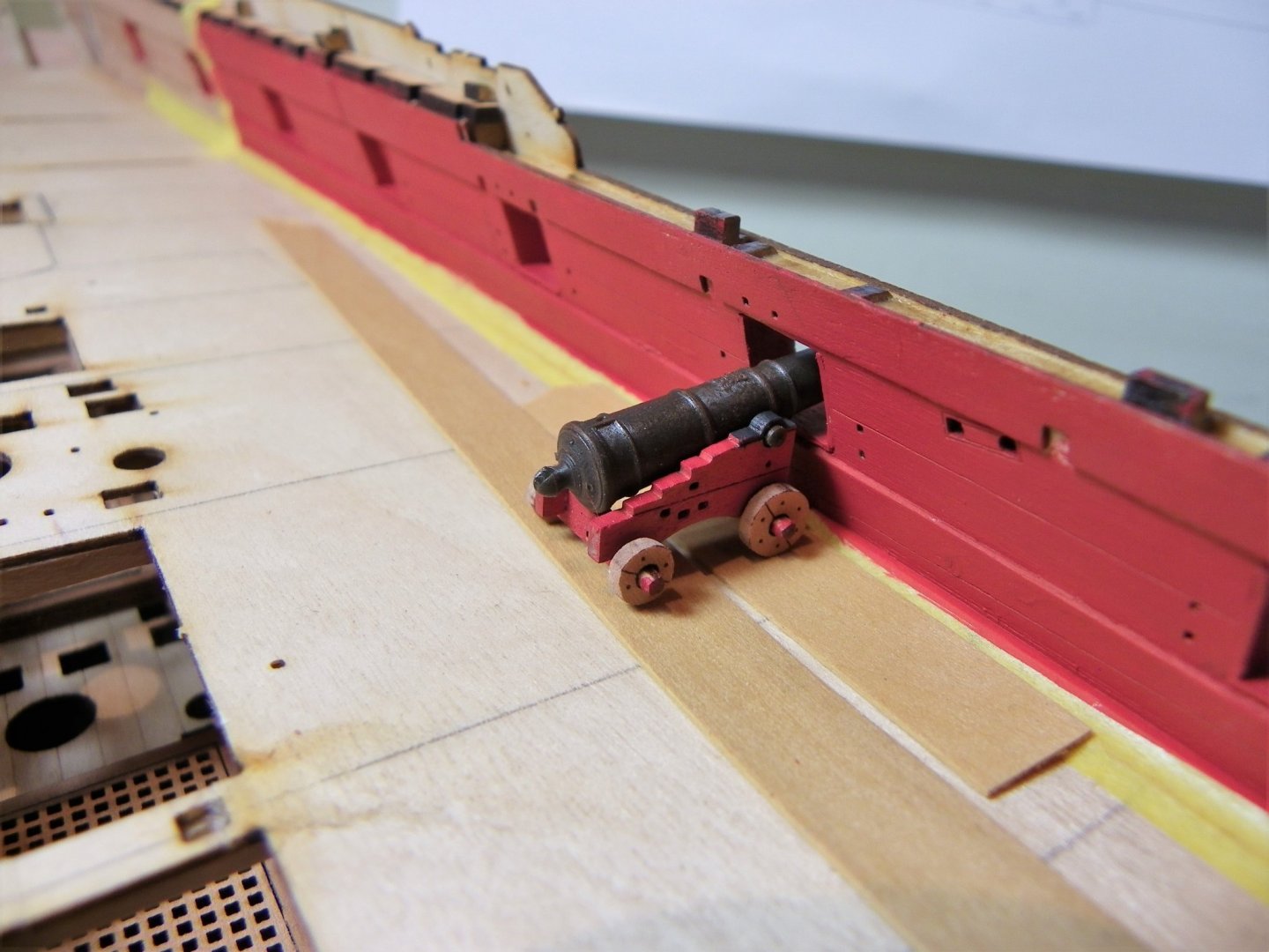
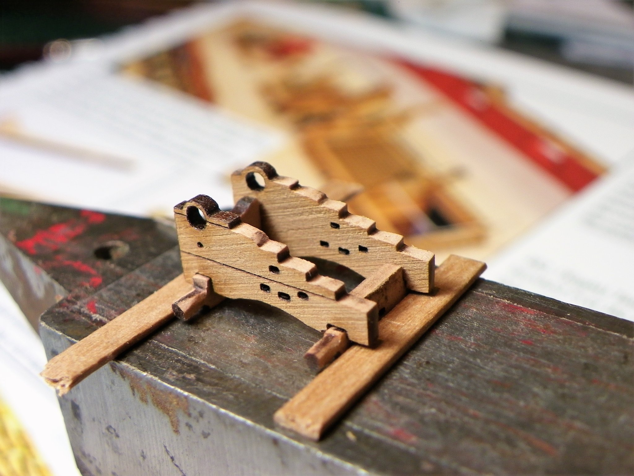
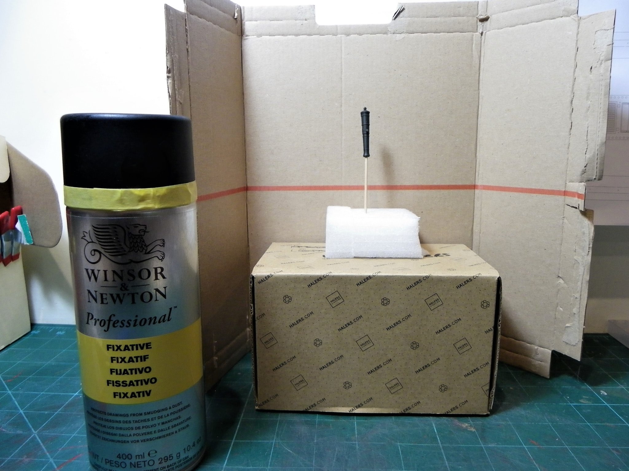
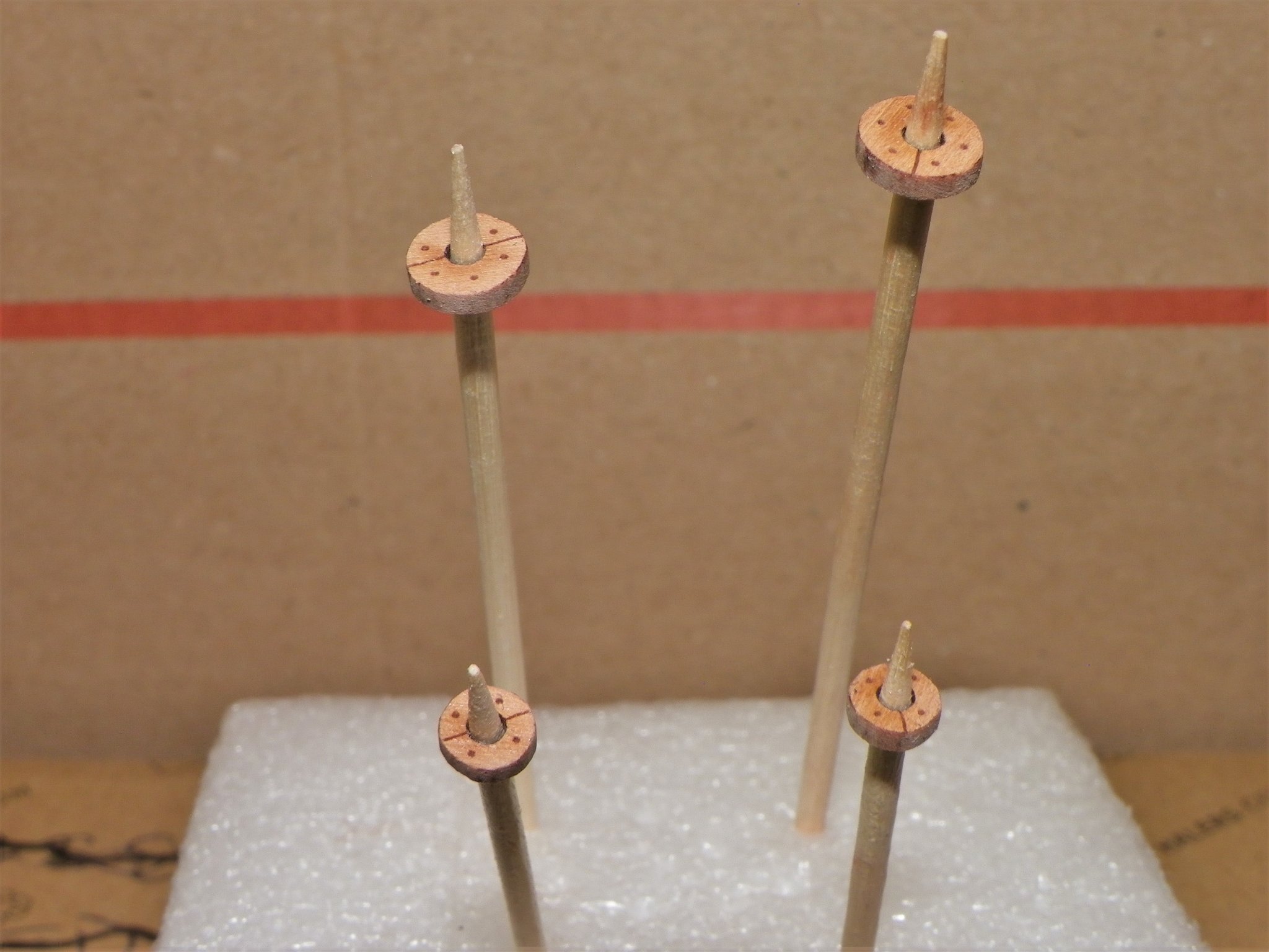
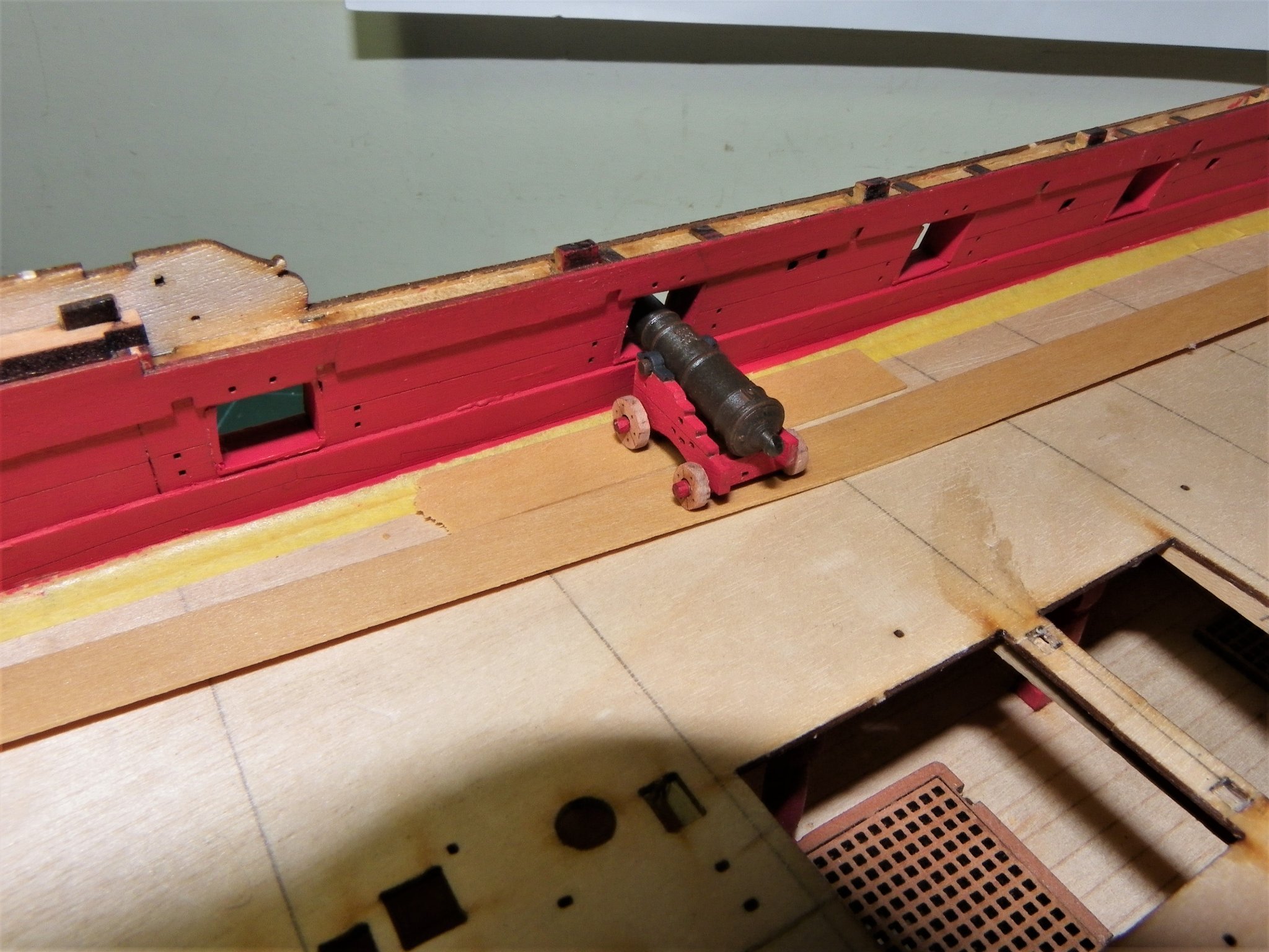
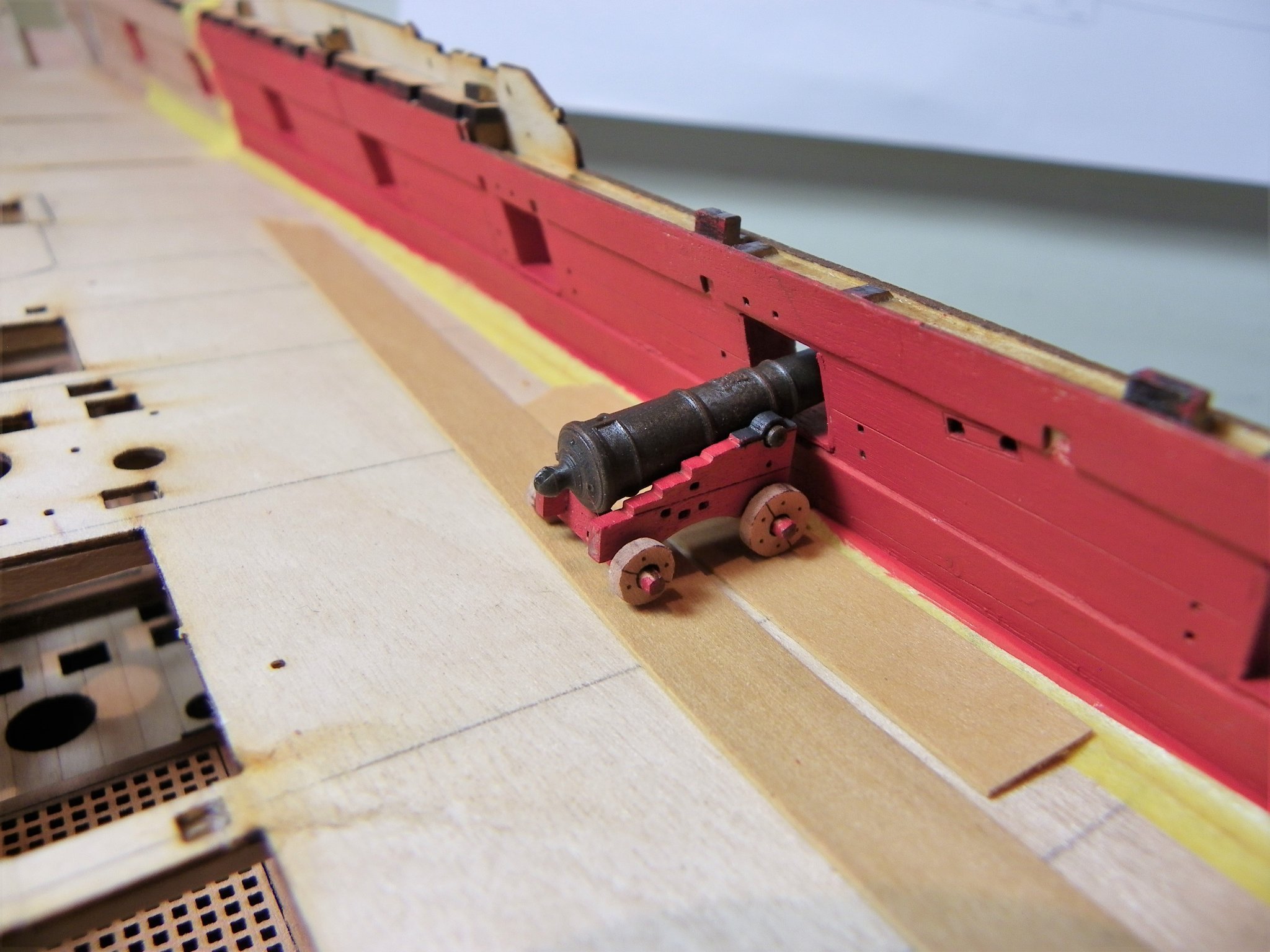
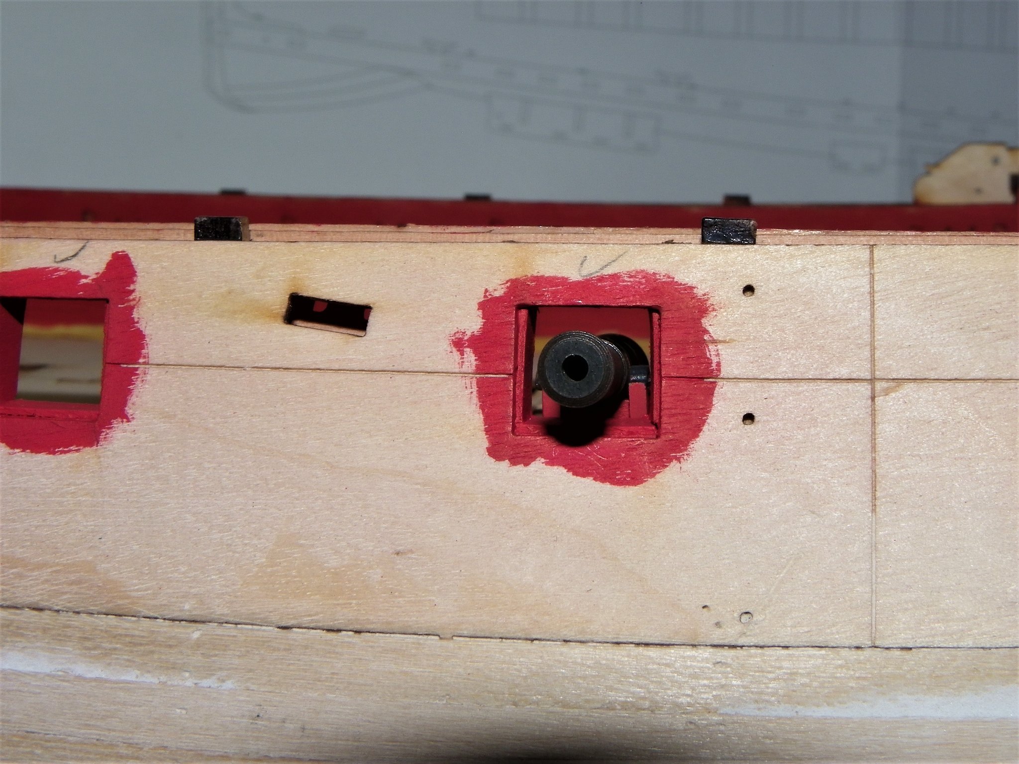
Post Thirty Looking at the guns At this point I make up a gun because it will prove useful in checking the level of the ports. Sphinx was fitted with Armstrong pattern Nine pounder guns which had a length excluding the cascobal of 7’ 6”. The barrel The kit has resin guns which are spot on for scale, and look very realistic, incorporating both Royal cypher and vents. They are so impressive that for the first time in my model building career I will forsake the blackened brass versions I usually favour. The muzzle face is nicely finished, the bore is scaled, and the reinforcing rings cleanly moulded. These barrels need no cleaning up such as the removal of moulding lines etc. When I think back to the appalling Amati guns supplied with their Pegasus kit, this is light years ahead. Well done Chris. The Carriages The good These are nicely finished in Pearwood. The trucks are engraved with both bolt holes and section joints, and the Brackets have the engraved planking line which represents the two parts that usually made up the Brackets. In reality these were secured with iron straps on the inside of the carriage. I am pleased to see that the trucks have round holes rather than the square versions supplied with the Alert kit. Chris has innovatively designed the capsquares as an integral part of the brackets. This has the advantage of securing the barrels, always a fiddly job when capsquares are separately added. This also makes it easier to add the Capsquare eye and joint bolts. My initial slight reservation about whether the capsquares looked too chunky was dispelled once I had assembled the gun. The not so good I am still not a fan of the provided etched eyebolts for the brackets. They look clunky to my eye, and the Breeching bolt lacks the ring thro’ which the breeching rope passes. As with my previous builds I will replace these with more convincing Ring bolts and tackle loops. 03531(2) Gun Carriage as fitted to Cutter Alert model. I find that Amati fine eyepins and rings are perfect for the Breeching rings. Even with these deficiencies which are easily addressed the guns overall are very nice, similar to to the ordnance supplied by Chuck with his Syren models. Assembly First job, gently remove the char from visible edges, I use a home made sanding stick for this purpose. 0873 Secondly, gently round the truck axles to fit thro’ the trucks. This takes very little, a slight rounding on the corners is sufficient. To assemble the guns the brackets require pre-painting because once the barrels are in place access to the inner areas is limited. 0915 The Trucks are fitted on a wooden toothpick to sand off the char around the rims. With the char left in place it looks like the iron rims fitted to land based guns, a real no,no, onboard a ship. With the trucks fitted to the axles I am pleased to see there is sufficient length to drill micro holes to take the keys. Fettlin’ the barrels. This is required before they are fitted to avoid any marring of the carriage paintwork. I am looking at using weathering powder to to create an ‘iron’ finish, using Chuck’s approach. Wash the barrel. Spray with fixative, I use Winsor & Newton professional. Apply weathering powder, and buff off with a soft brush. 0891 My pop up spray booth. 0887(2) The basic resin gun. Under macro I note a fault with the button, unfortunately on the top side. I checked the rest of the guns and a similar deformation was present in a further five of them. Not a great problem to put right, but it is an additional job to do. 0901(2) Fixative applied. 0903(2) Weathering powder applied, I used Revell Rust Red. 0907(3) Finished gun with buffed surface. Before fitting the barrel between the Brackets I paint the capsquares. For this I use Vallejo Black Grey which gives a good scale iron effect. This area is too small to apply weathering powders without the risk of marring the paintwork. 0927(2) 0931(2) 0940(2) Fairly satisfied with the result. Final check, how does it sit on the deck. 0944 0947 0951 0955 This gun remains unfinished; I’ll re-visit the ordnance later, but for the present it’s back to port lining. B.E. 26/10/21
.thumb.JPG.d1bf84cbbb2448fd6d330850256be75d.JPG)

.thumb.JPG.3f9f39105bcb2a785561b75dbaaa6f20.JPG)

.thumb.JPG.7e6092ef71eecfe745ef263a8d58883e.JPG)
.thumb.JPG.94debeba5813aab5dc2ee2dee6984f96.JPG)
.thumb.JPG.d989392f86a8bafb94f4735ccd550a04.JPG)

.thumb.JPG.d285596ce73a80a7ec41894f8ec9abe5.JPG)
.thumb.JPG.a26806b782476adf84b2ed47e626a2f2.JPG)
.thumb.JPG.842033e898a2456ffe14ec3a2c49bdcf.JPG)

- 857 replies
-
- 26
-
-

-
- Sphinx
- Vanguard Models
- (and 1 more)
-
That’s the beauty of wood not much that cannot be repaired, unless of course your cat is into arson. 😉 Then I should worry. B.E.
-
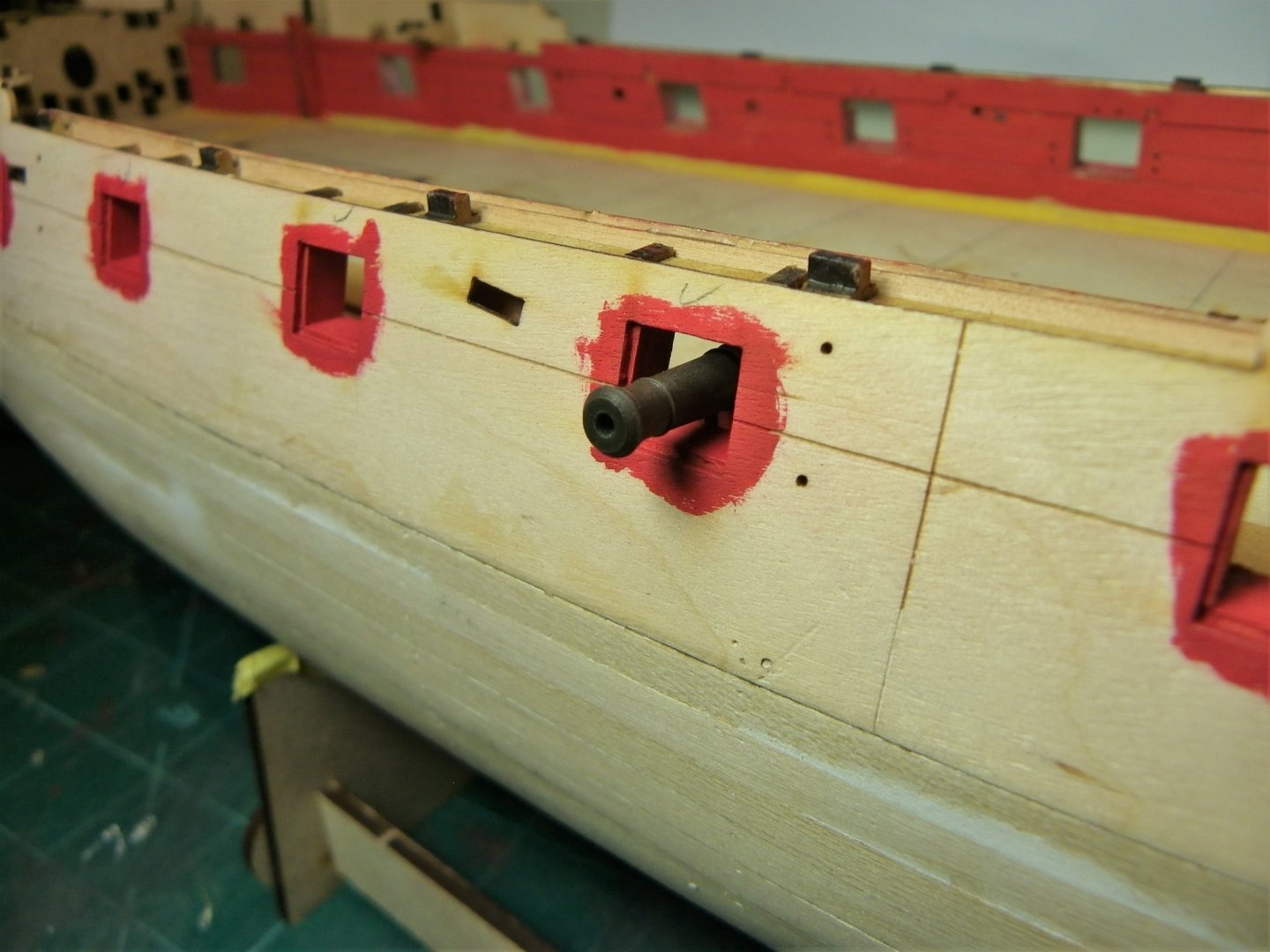
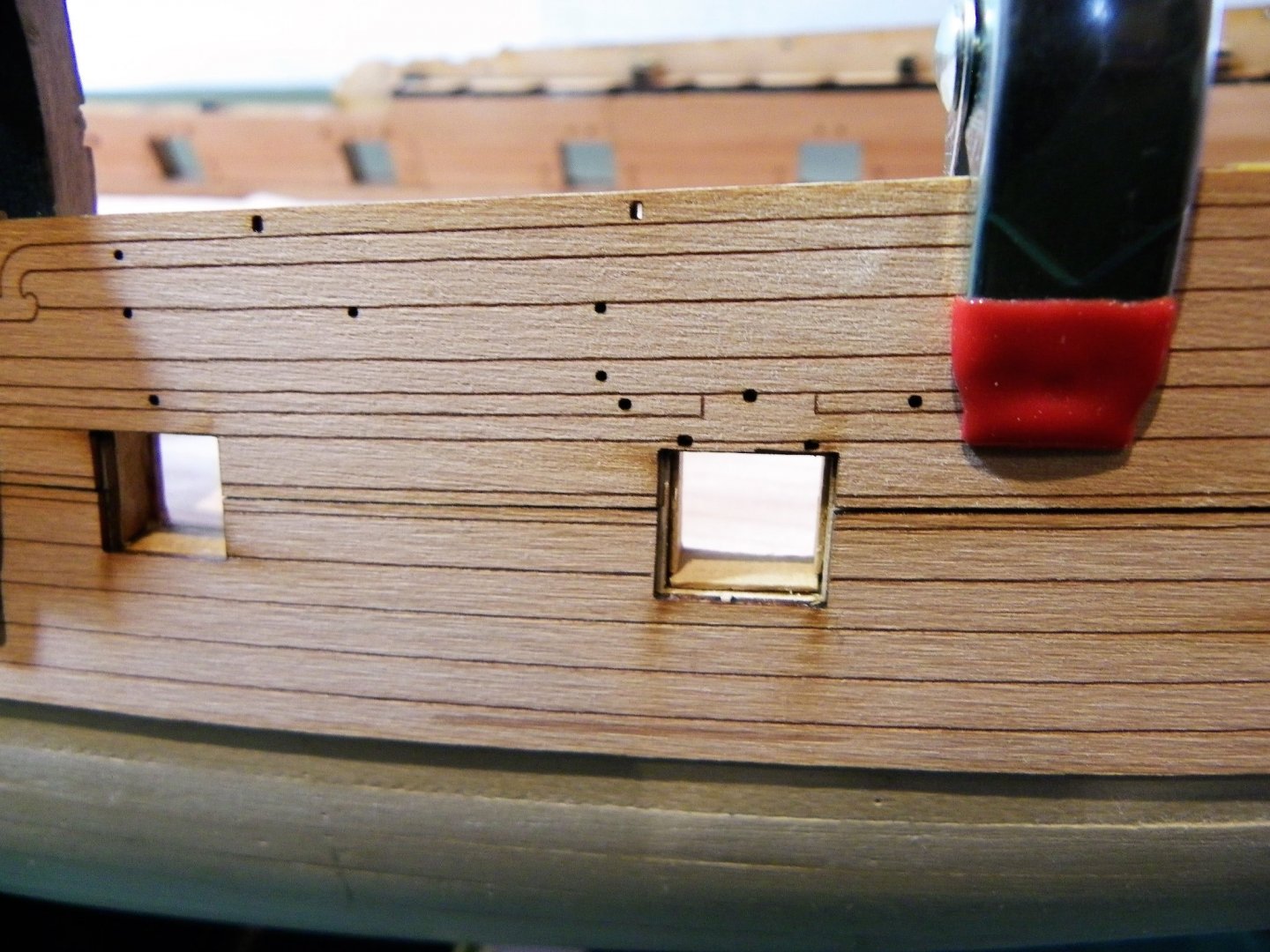
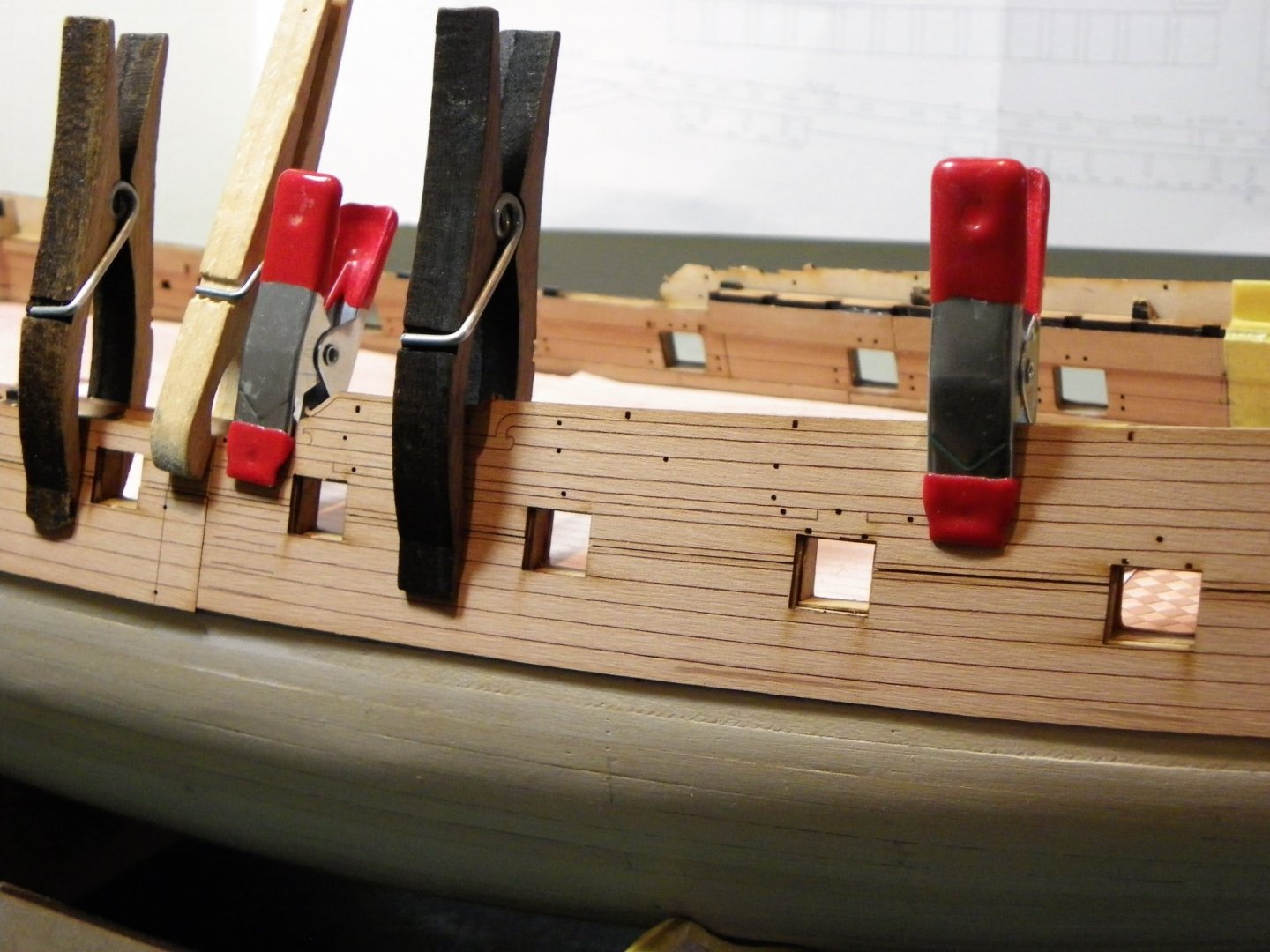
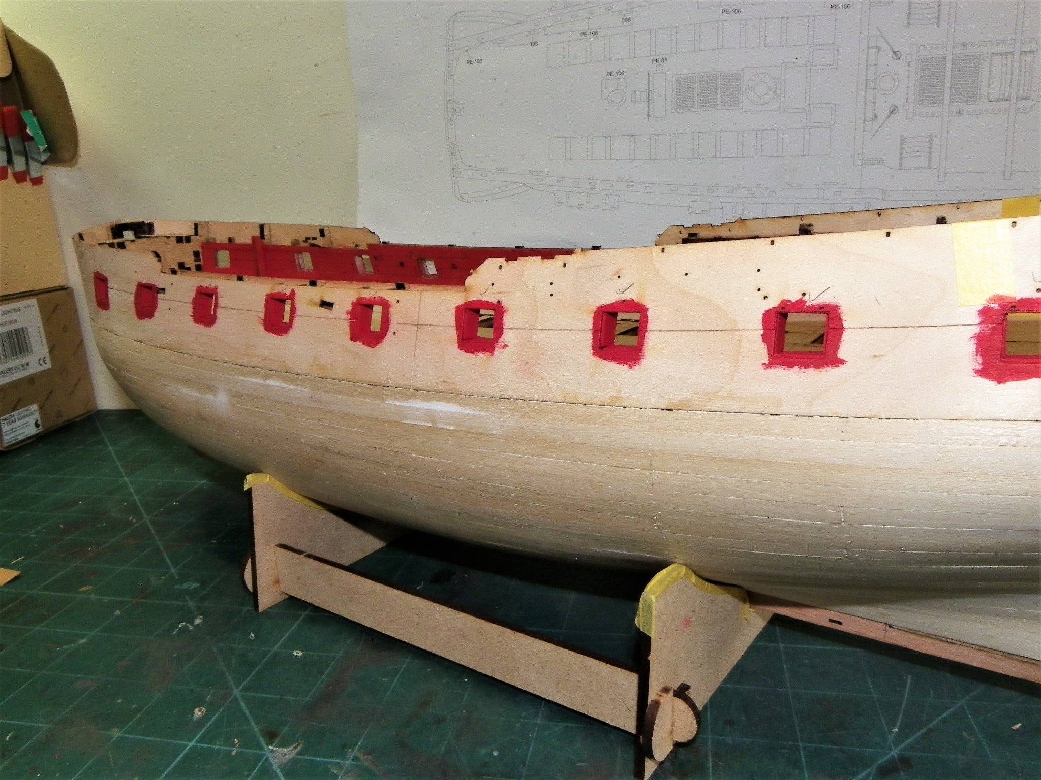
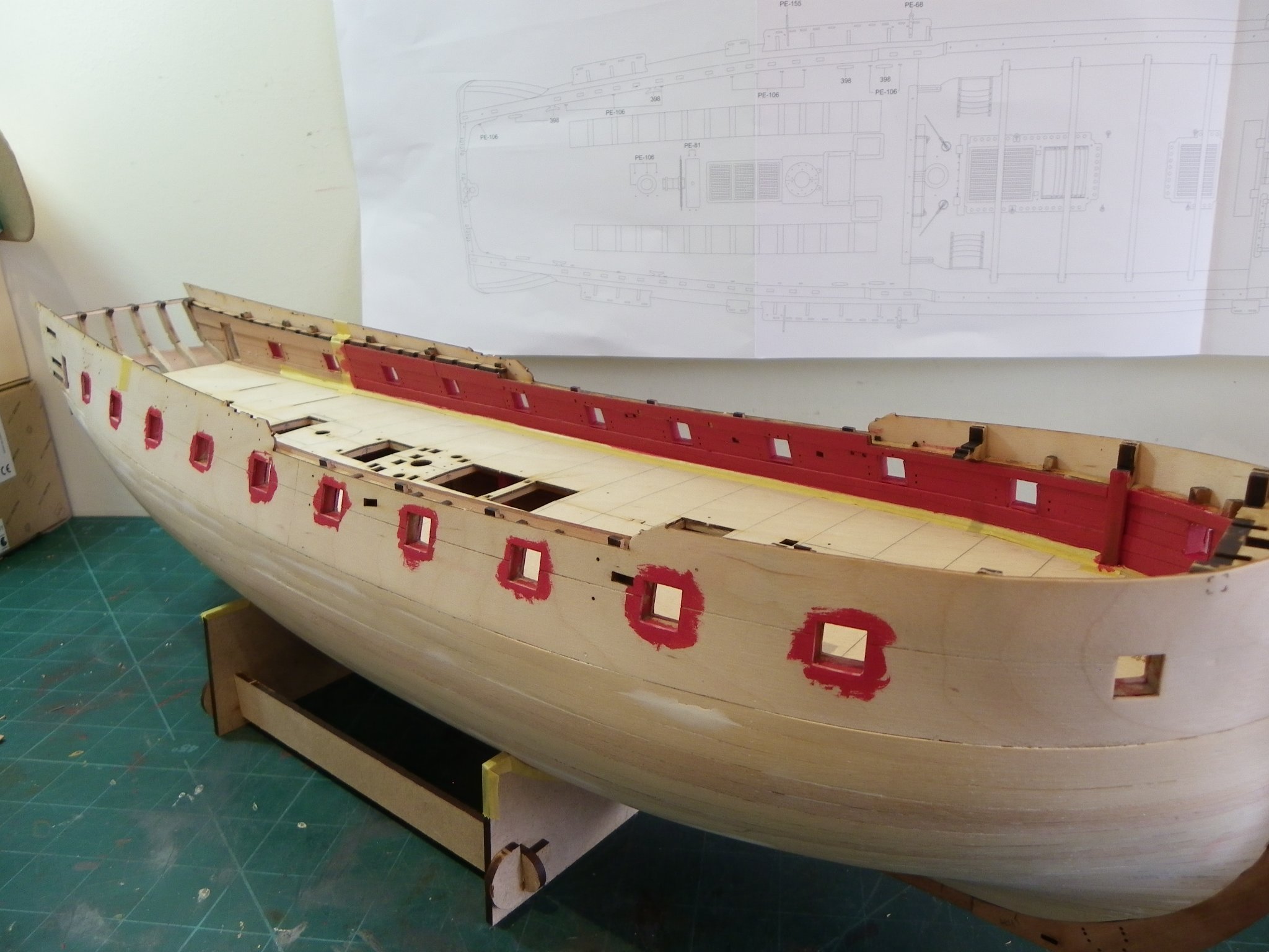
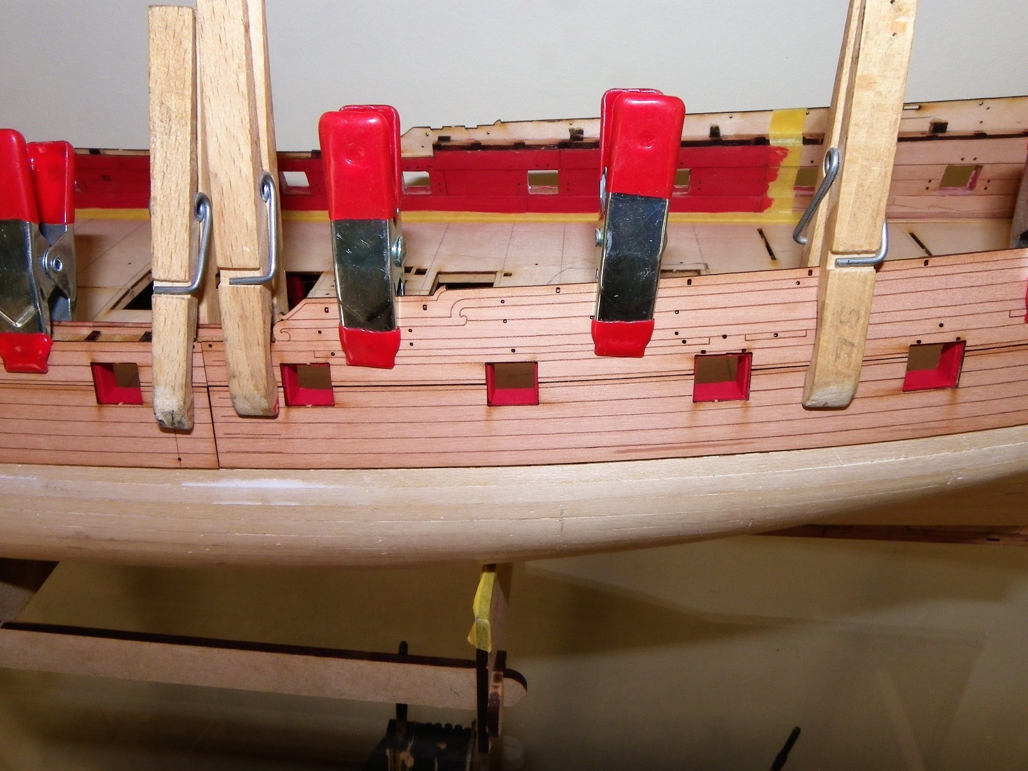
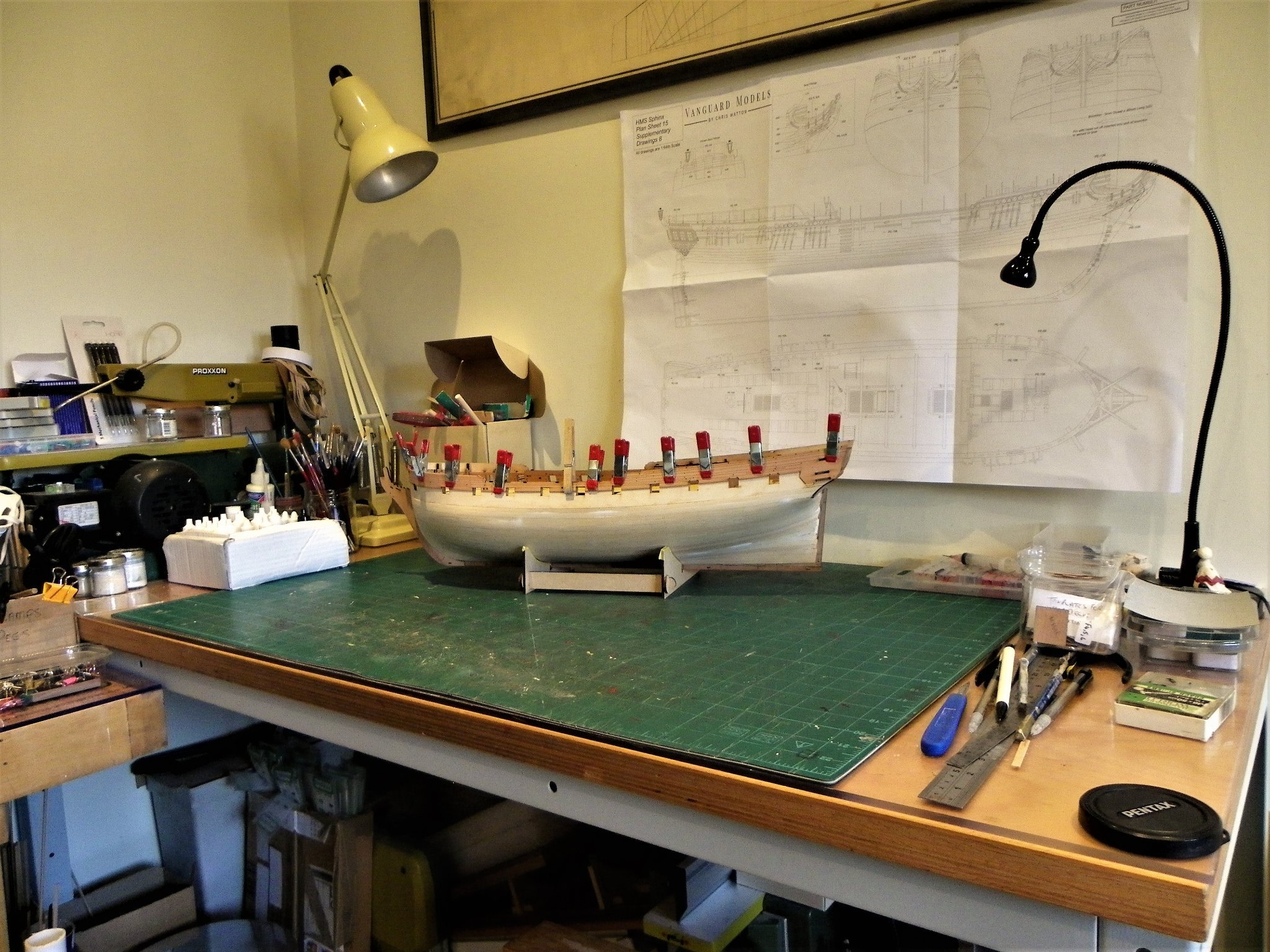
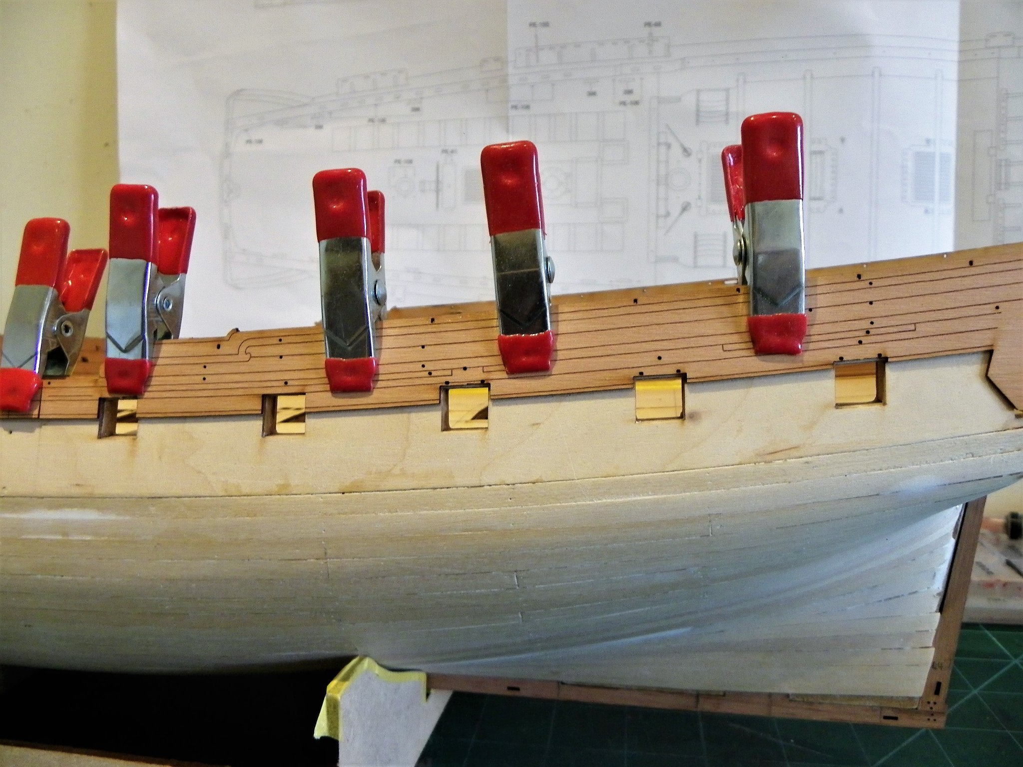
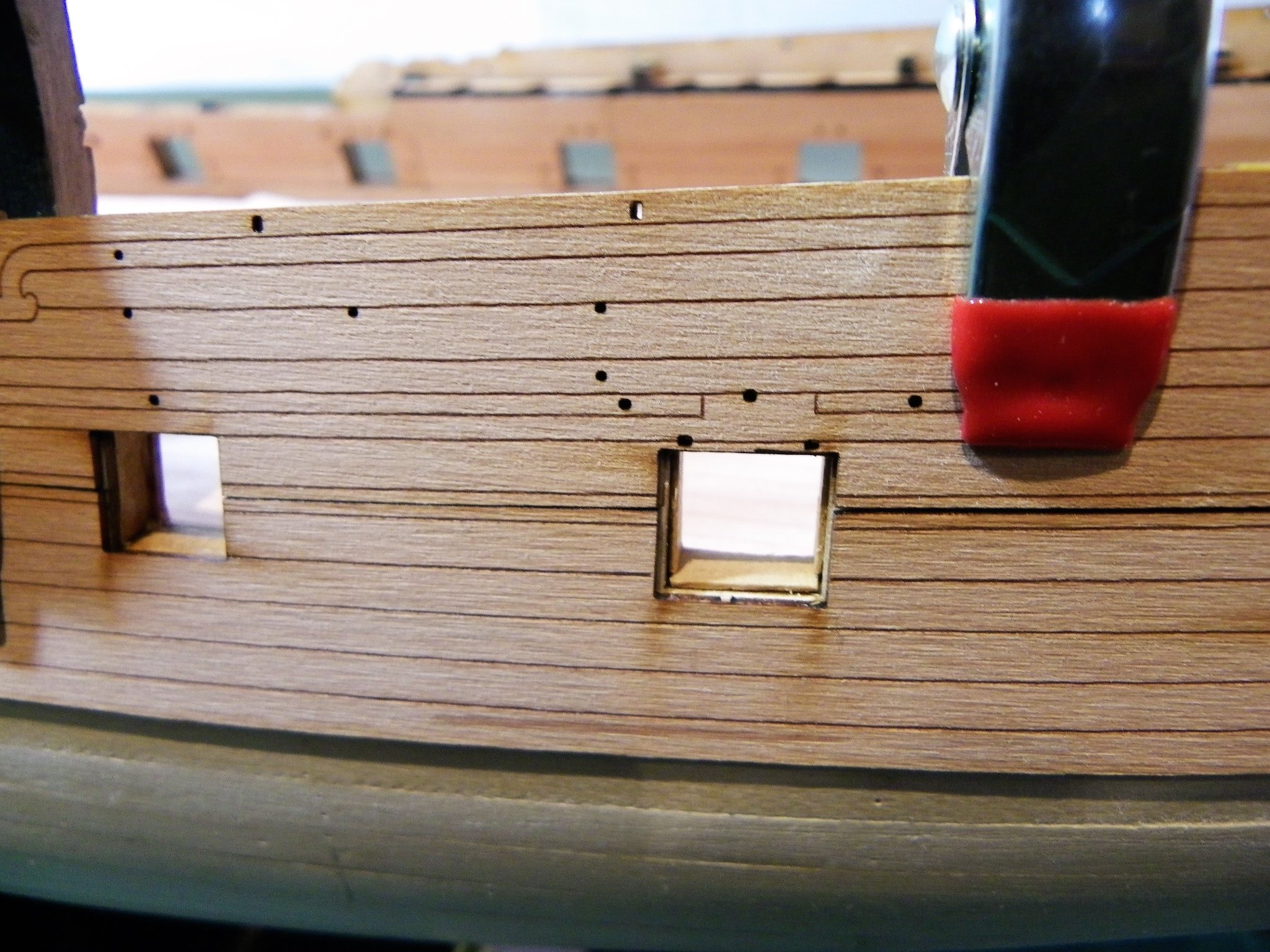
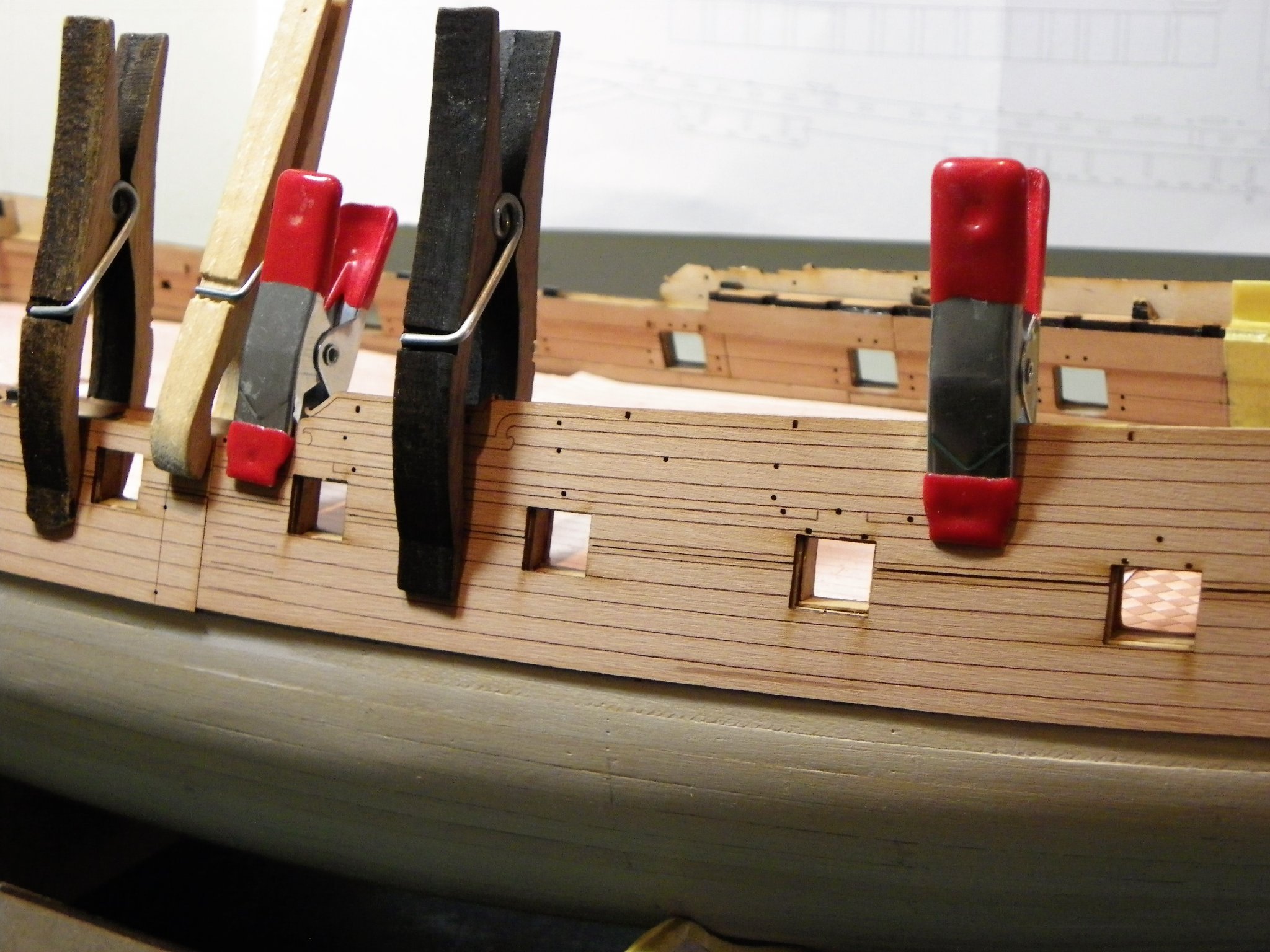
Cheers Guys and thanks for looking in Thomas, I'm still enjoying your rather tasty Syren build. Post Twenty-nine Gun port fettlin’ I have decided to line the ports, but before I begin I lay a coat of thinned paint to the bulwarks. The outer patterns were trial fitted several times to reveal any mismatches which were cleaned up using scalpel and fine sandpaper. Not on the Pearwood patterns I hasten to add. 0879 To better get a clean line for the stops the outer edges of the Gun port pattern are painted for a better contrast. Any hairline gaps between the gunport pattern and frames were filled and sanded smooth. 0871 I begin with the bottom stops and set them level with the inner edge of the gunport pattern. This is the easy part, fitting the side pieces which need angling, somewhat more tricky. 0878 To accommodate the angled side pieces I use 10mm wide strip, and the simple expedient of inserting the strip thro’ the ports and marking the angles for cutting. 0881 Looking at the inboard bulwarks on the Port side where the lining have been added. 0880(2) I think the Vallejo Flat Red is spot on for the shade I’d envisaged. The real test is how do the ports look with the planking patterns in place. 0884 The photos reveal a little fettlin’ is required here and there but overall, I think it has worked out just fine. 0882(2) A repeat exercise now required on the Starboard side. It will be awhile before those pretty planking patterns are fitted. B.E. 25/10/21

.thumb.JPG.2f9afcde929bb048d5fe49dad97d5524.JPG)

.thumb.JPG.a6054dfa59f62ca06cc922f3b73ad477.JPG)

- 857 replies
-
- 21
-
-
- Sphinx
- Vanguard Models
- (and 1 more)
-
There were small glazed lights with half shutters directly below the Poop deck to serve the cabins along the Quarterdeck at the stern. B.E.
-
Thank you Glenn (UK), and Glenn (USA), and thanks for looking in Malcolm. @ Glenn (USA) - this is a kit to savour, like a fine old vintage wine, so much scope to play with it. Altho' I'm working on it most days, all being well, I fully expect to be still going this time next year. In a funny sort of way, Chris's design with so many pre-formed parts almost encourages a clik and fit quick build mentality, a fairly finished look can be achieved in a short time. It's not that easy, there's a lot more to the kit than that. Cheers, B.E.
- 857 replies
-
- 6
-
-
- Sphinx
- Vanguard Models
- (and 1 more)
-
That must be a relief Jacek, the planks seem to be sitting nicely against the stem at the bow, did you have a rabbet to assist the process. B.E.
-
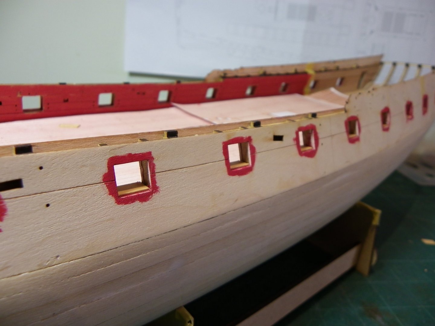
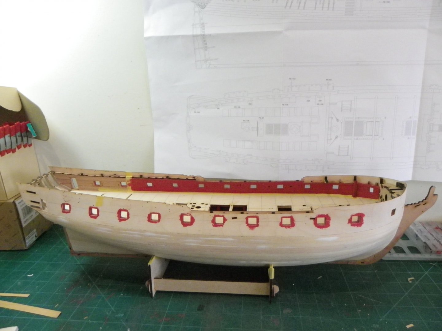
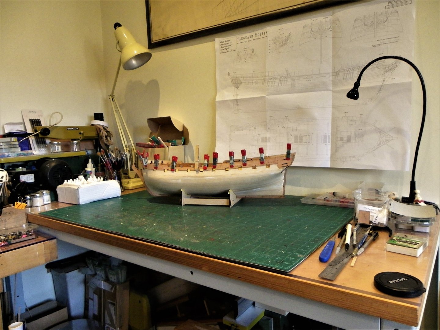
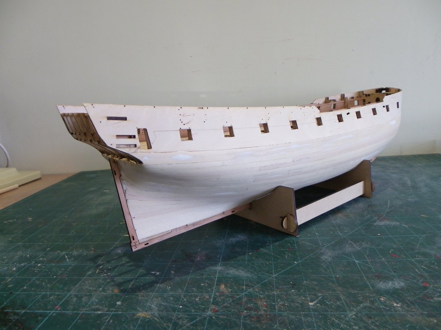
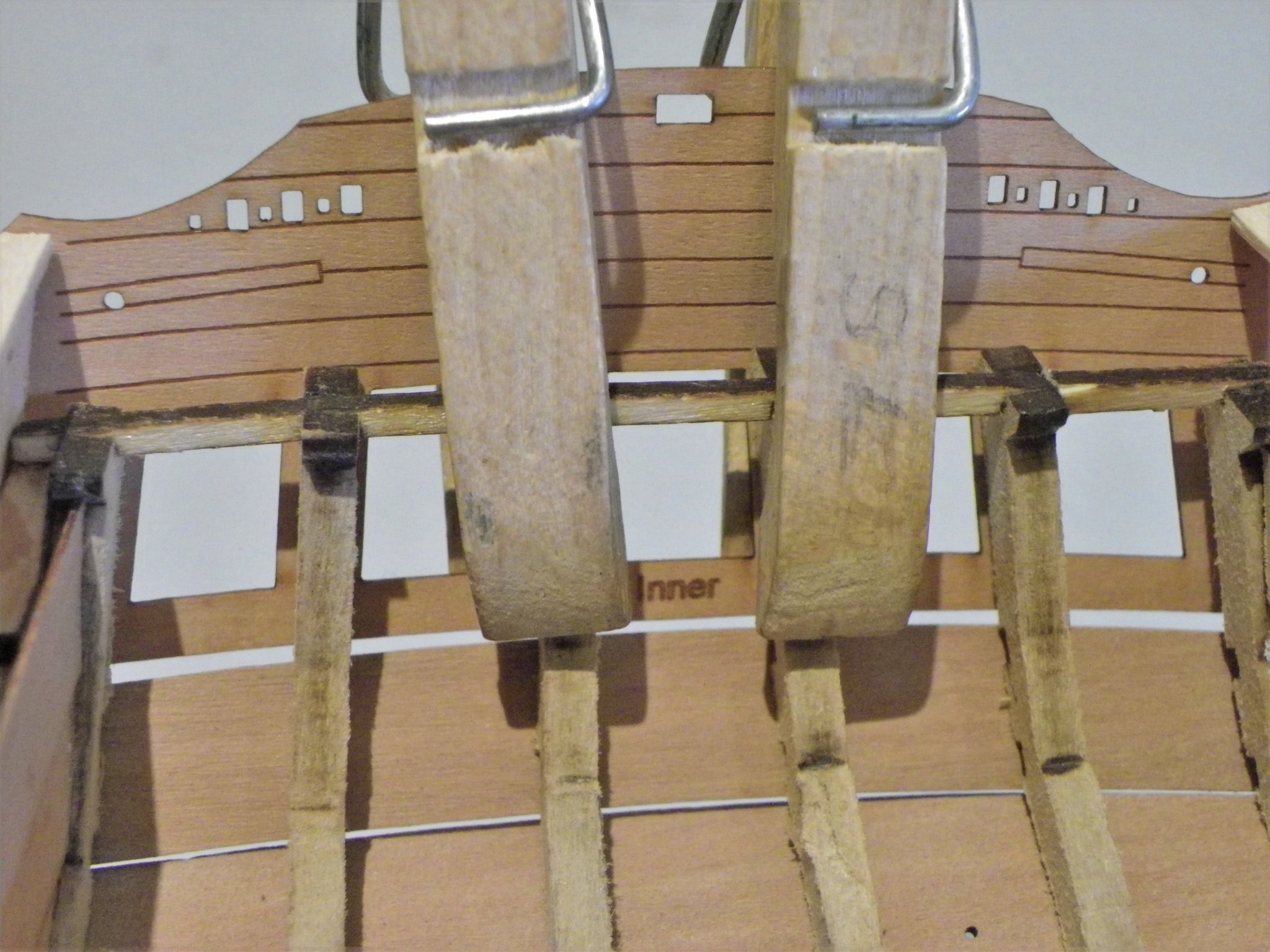
Thanks Guys for your support. Post Twenty-eight Attending to inboard works With the major dust fest completed, it’s time for a GTU before I get down to applying some paint to the inner bulwarks. 0837 This is about as good as it gets during a build. 0838 Trial fit of the Topsides planking, careful attention to alignment with the ports is the prime concern here. 0857(2) I am quite impressed with these pre formed topside planking strips, they look good and certainly save all that planking between the ports. Fitting them will have wait until I have planked the deck. Painting the inner bulwarks I have decided to use Vallejo Flat Red, applied by brush, but before I begin I need to consider the inner surfaces of the gun ports. They have an mdf core sandwiched between thin layers of Pearwood. I am thinking that the ports should be lined even tho’ they have no lids, except in relation to the stern area and Bridle ports. They were lined on Pegasus, and the painting of Sphinx does appear to represent them. I do like the look of port Stops and I am tempted to add them using 0.6mm Boxwood. Strictly speaking the internal quickworks and spirketting should cover the linings, too late for that now, but as it is all to be painted that aspect will not be obvious. This is mainly viewed as an external feature. 0841 This is a mock-up of a lined port using 0.6mm Boxwood. This thickness equates to 1½” which is about right for the stops. Lining the ports is a tricky business, particularly the side pieces which must be angled to fit the port; and there are 44 of the beggars to make. 0848 I don’t want to mess with the outer planking patterns so I need to ensure that they meet the edges of the framing exactly, if I’m going to proceed. On the subject of ports I was a little surprised, and somewhat relieved, that sweep ports are not represented on the model, unless of course they had been laser cut by Chris. Pegasus had them, and they are shown on the Admiralty plans; they are not included on the plans for Sphinx. Neither are they depicted on the Marshall painting. The Marshall paintings do show them on the 6th rate Kingfisher, but not the Frigate Enterprize. 0866(2) I’ll faff around with this awhile, to assess any potential issues, but I have given the inner bulwarks a very light sanding and the application of diluted wop as a base preparation for the paint. B.E. 23/10/21

.thumb.JPG.1d8d299b01cb35e56890696eadf3e8c3.JPG)
.thumb.JPG.d7e7e47991c81e5579ba409426ea3421.JPG)
- 857 replies
-
- 20
-
-

-
- Sphinx
- Vanguard Models
- (and 1 more)
-
The Heller kit is correct, on French 74's the upper gun- deck ports had no lids, the recognised authority on French 74's, Jean Boudriot, confirms this in his four volume work on the subject. On British ships ports along the open waist were also without port lids, altho' some may be fitted beneath the Foc'sle and Quarterdecks. Regards, B.E.
- 126 replies
-
- 2
-
-
- le superbe
- heller
- (and 2 more)
-
Hi, bitter, As far as the topsides colour is concerned, I was trying to replicate the look of those wonderful contemporary 18th c models, if it was good enough for the craftsmen of the time, it was good enough for me. There was a large element of artistic license used in the colours and decoration applied to both models and artwork, particularly on small ships such as Pegasus. Regards, B.E.
-
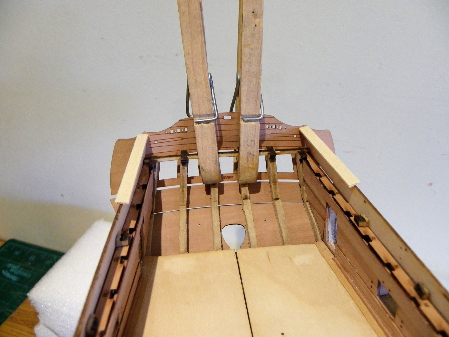
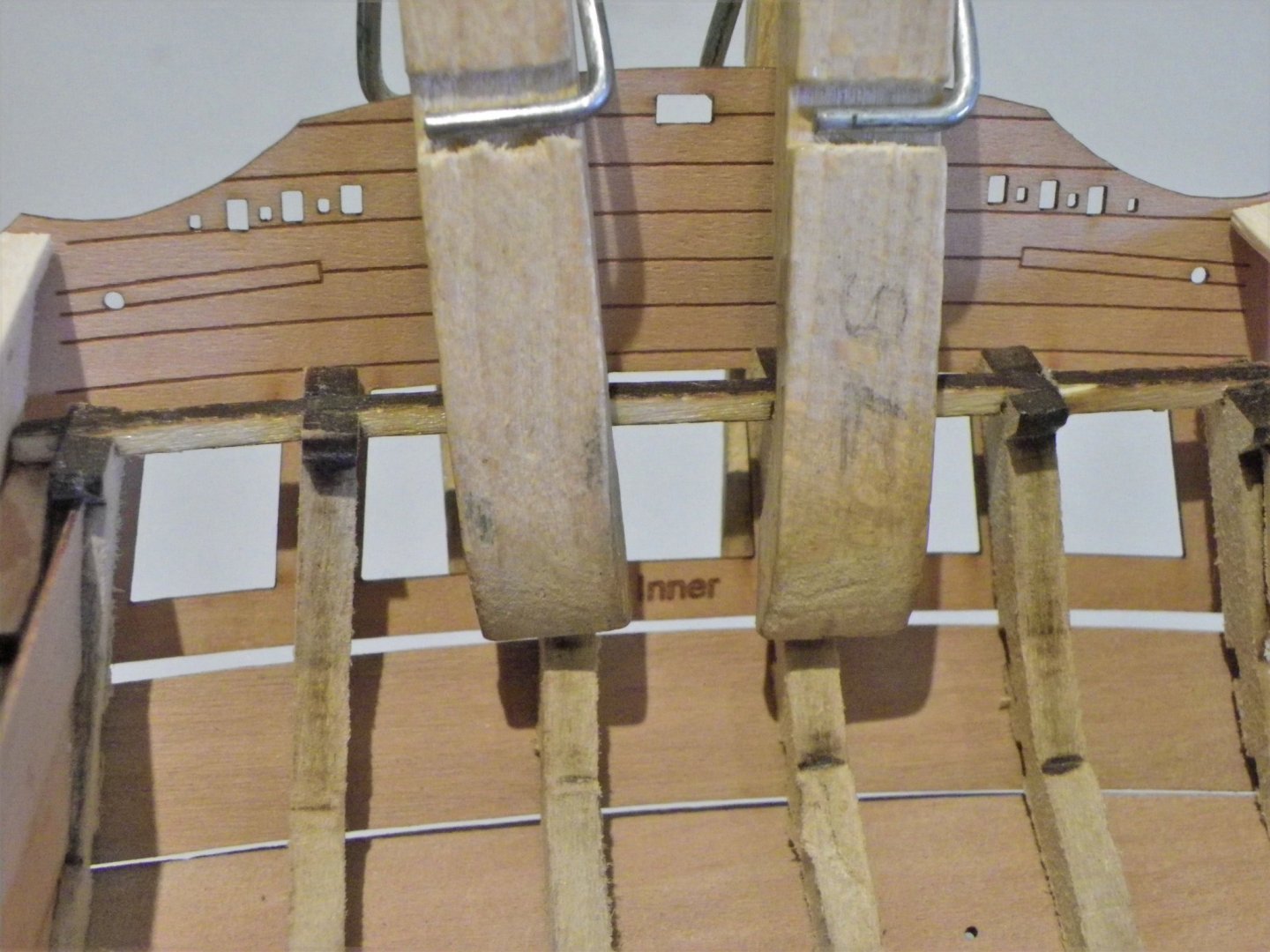
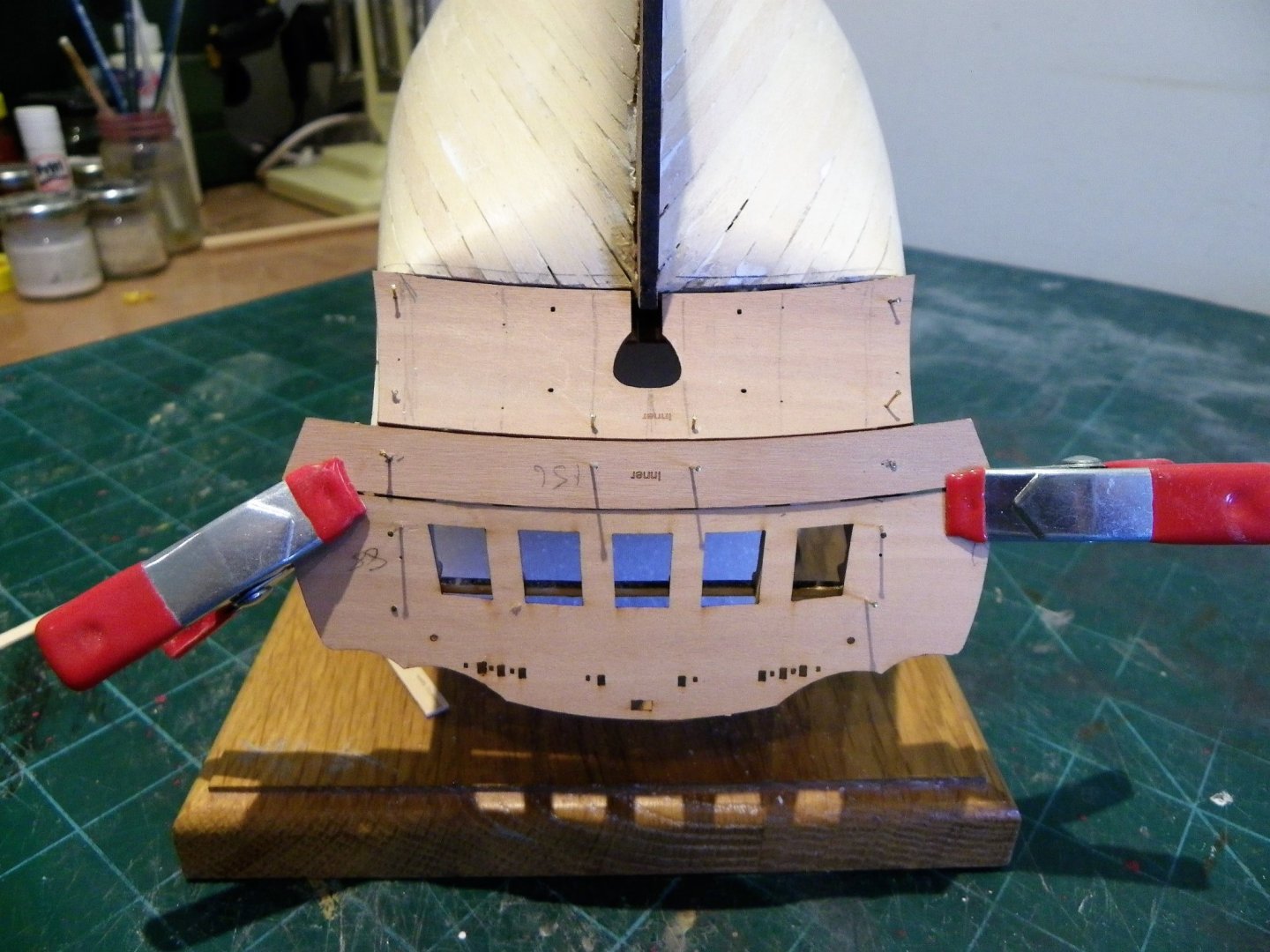
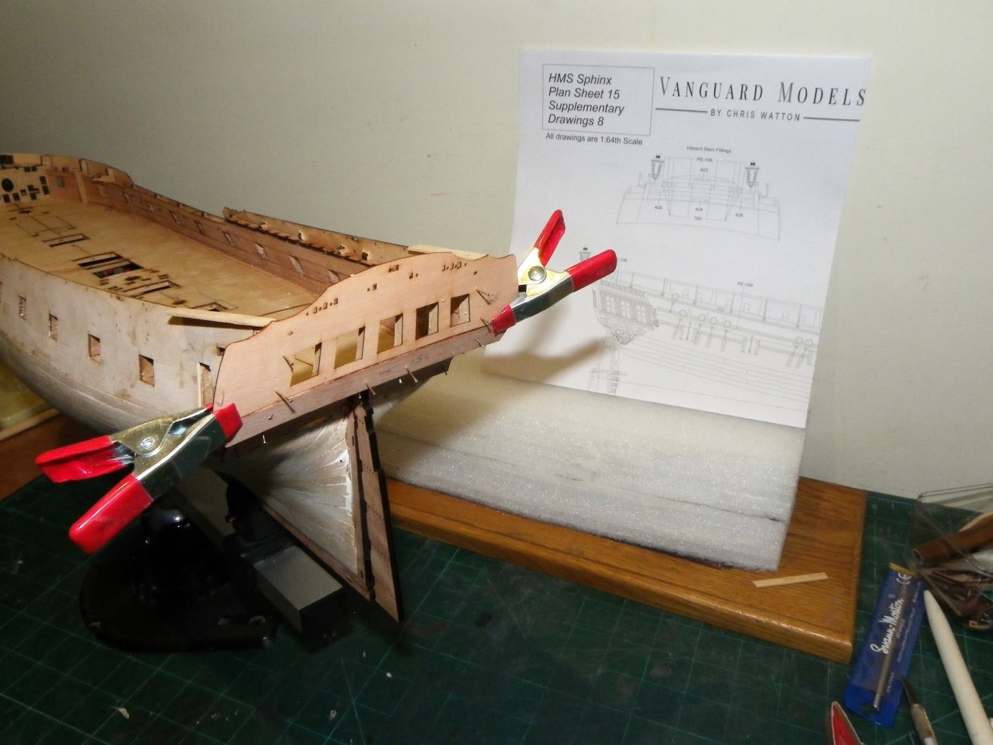
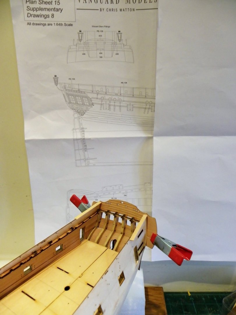
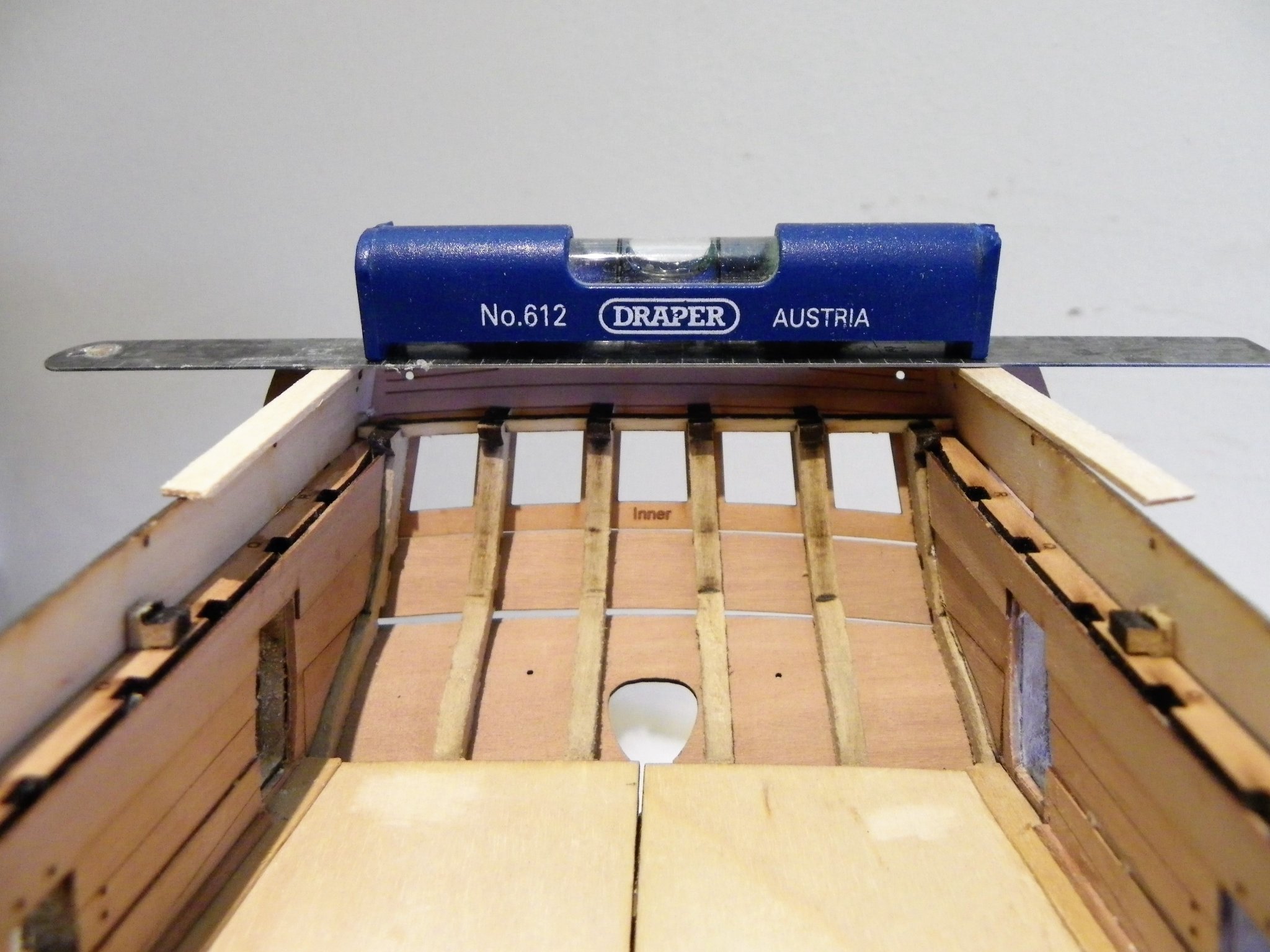
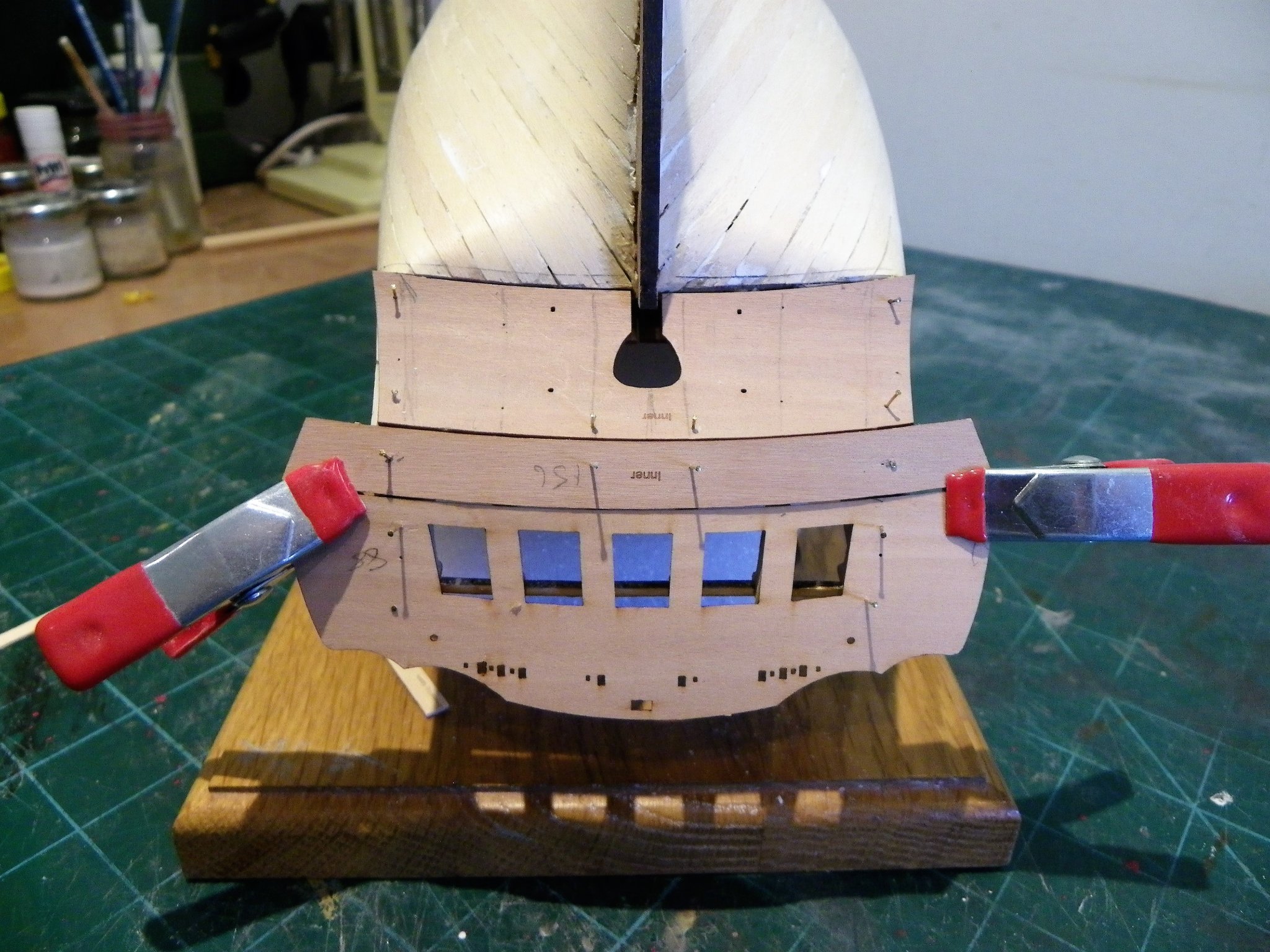
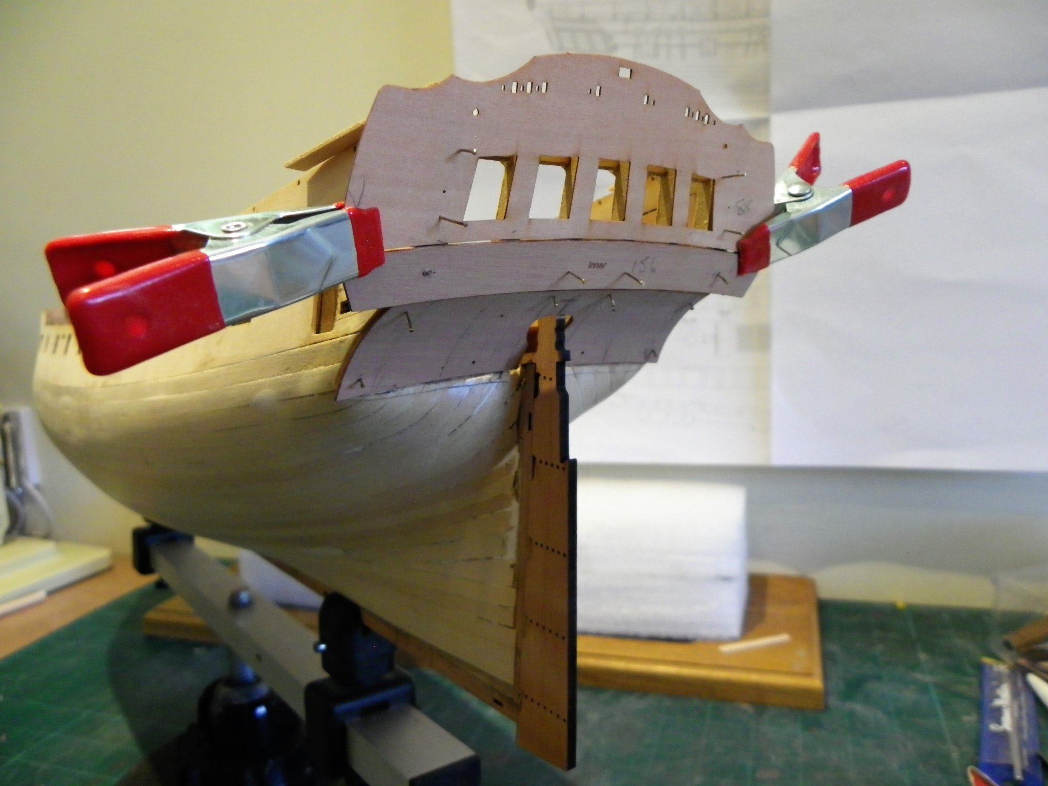
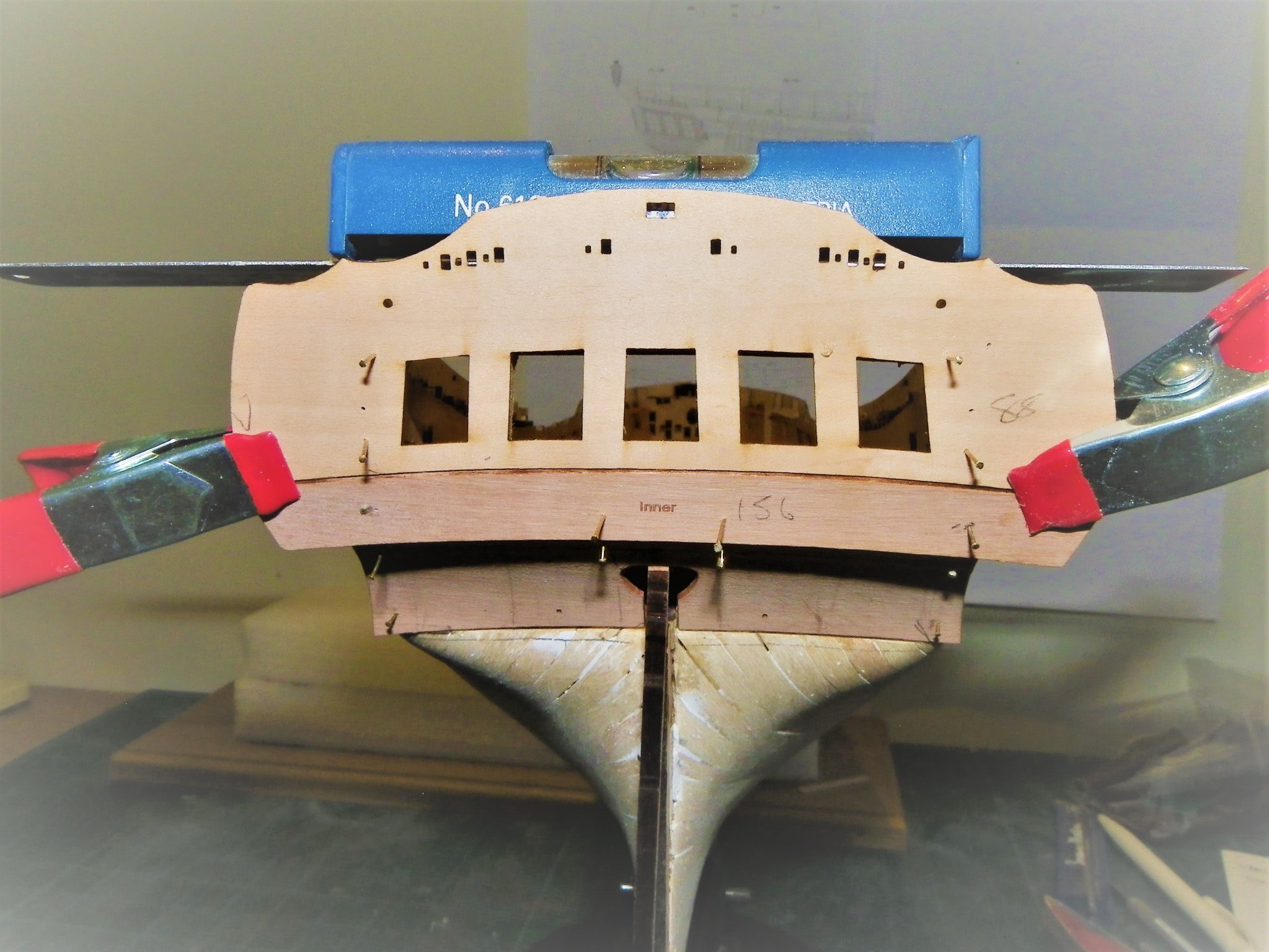
Cheers Guys, thanks for your comments and likes, it’s always good to reach this point in a build, before the next testy little exercise begins, which is about now. Post Twenty-seven That tricky business of the stern Getting the stern right is one of the key areas of a build, if this isn’t right nothing will be right. I am aware of the issue Glenn experienced in his build, and of the modification indicated by James for the positioning of the lower counter. My approach in relation to any build is to look at the stern area in its totality, with all parts temporarily fitted before committing to glue. In the case of Sphinx, trial fitting of the lower counter in conjunction with the upper counter inner (part 156) and stern facia inner (part 88) is necessary. I am working primarily from Plan sheet 15 which shows the Bulwark pattern, even with the addition of the 1mm capping rail, sitting a fraction below the rise of the Facia. It seems to me that one should start with the Facia position. 0808 Here you can see 1mm thick strips atop the Bulwark pattern to represent the capping rails. 0809 In this macro shot note where the lower line on the facia pattern sits level with the top of the stern frames. Note also how the Facia top sit just above the bulwark cap level. 0816 I am now able to invert the model and pin the Upper counter which then lets me see how the lower counter relates. It took several tweaks to get the two counters in the right position. 0829 0814 Back up the right way I check the levels across the Bulwark. 0822 0824 Looking at the set-up from all angles to satisfy my eye. 0825 I will leave the Facia and Upper counter pinned in position while I glue the lower counter in place. This approach gives me some assurance that when I come to finally fit the facia some steps down the line, any adjustments will be minor and I won’t have any nasty surprises. B.E. 21/10/21


- 857 replies
-
- 18
-
-
- Sphinx
- Vanguard Models
- (and 1 more)
-
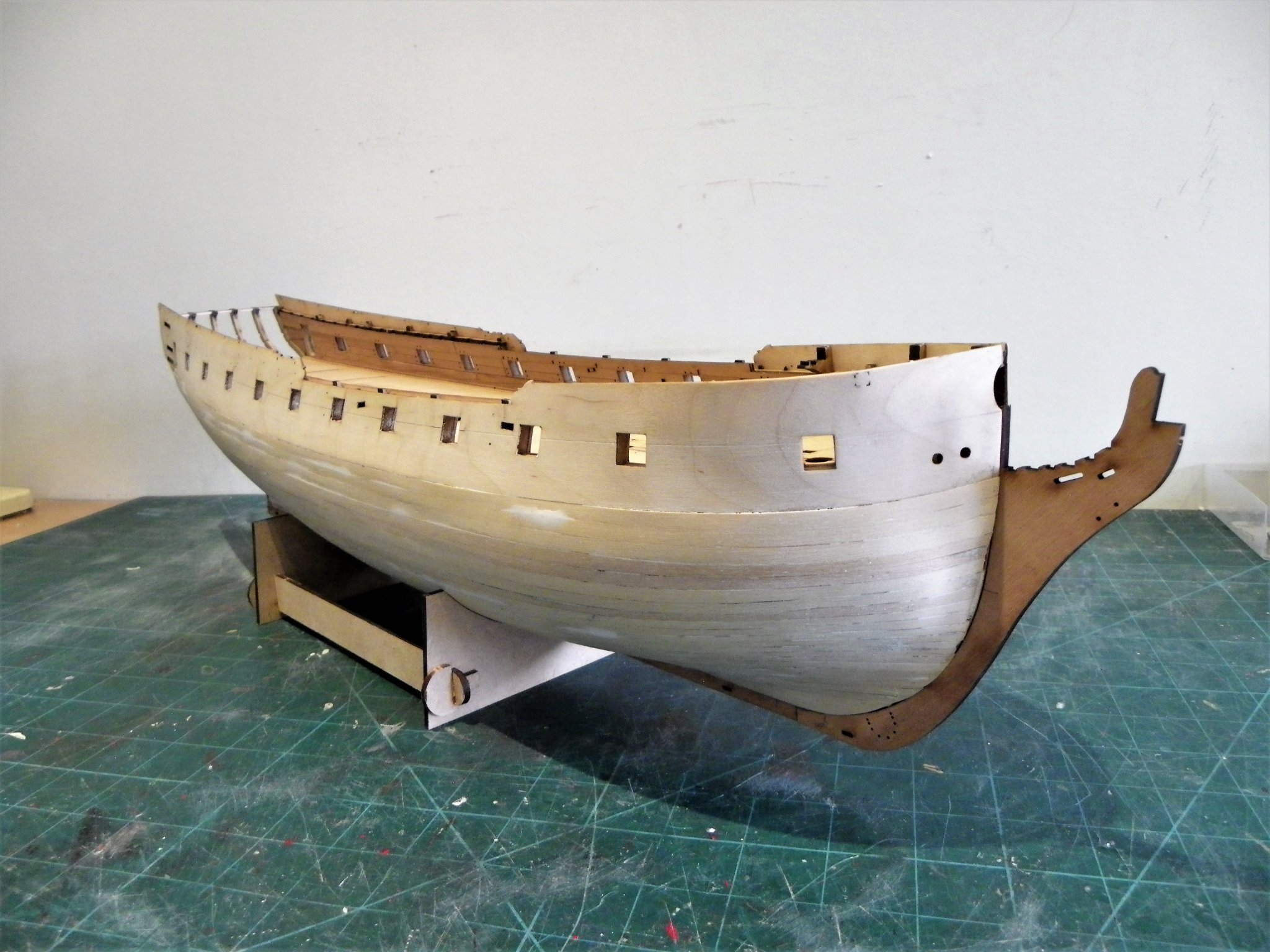
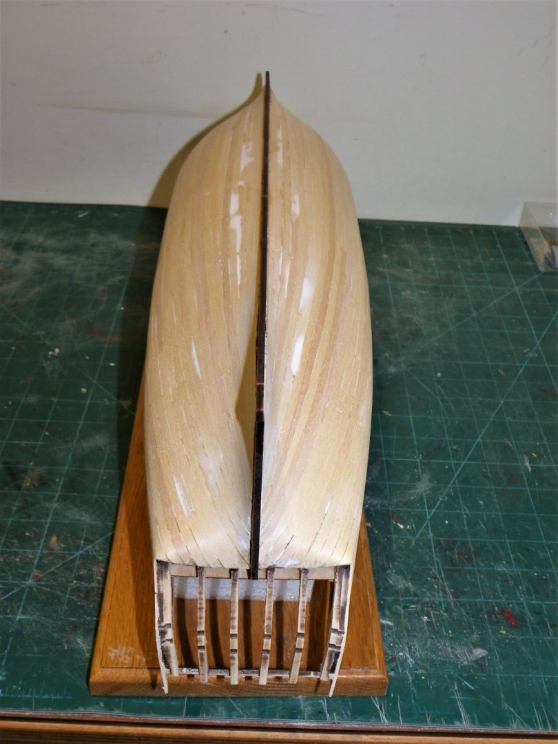
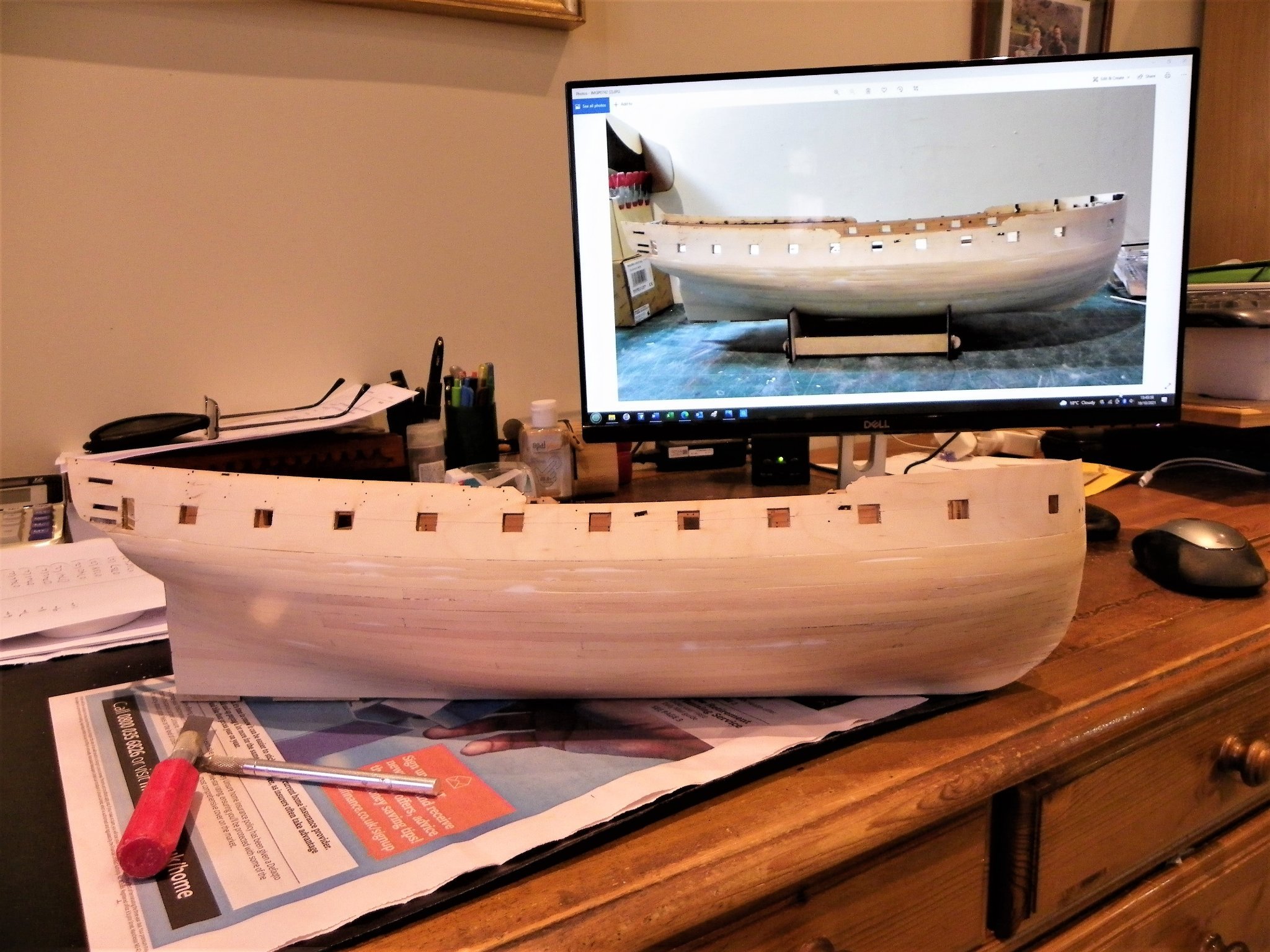
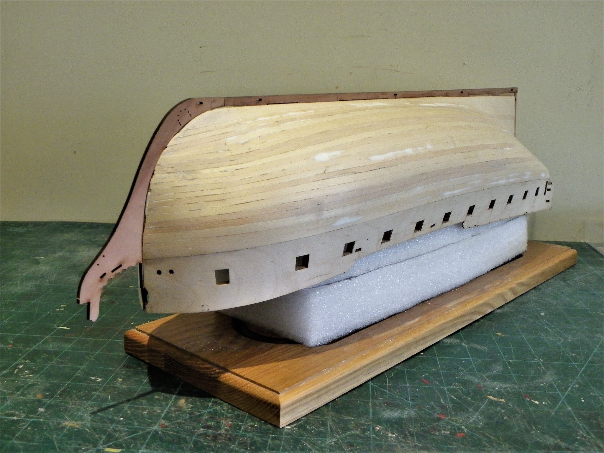
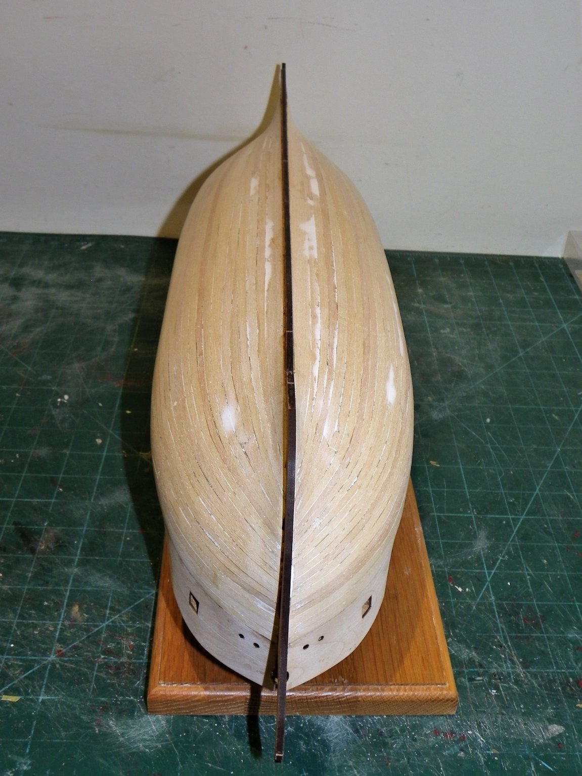
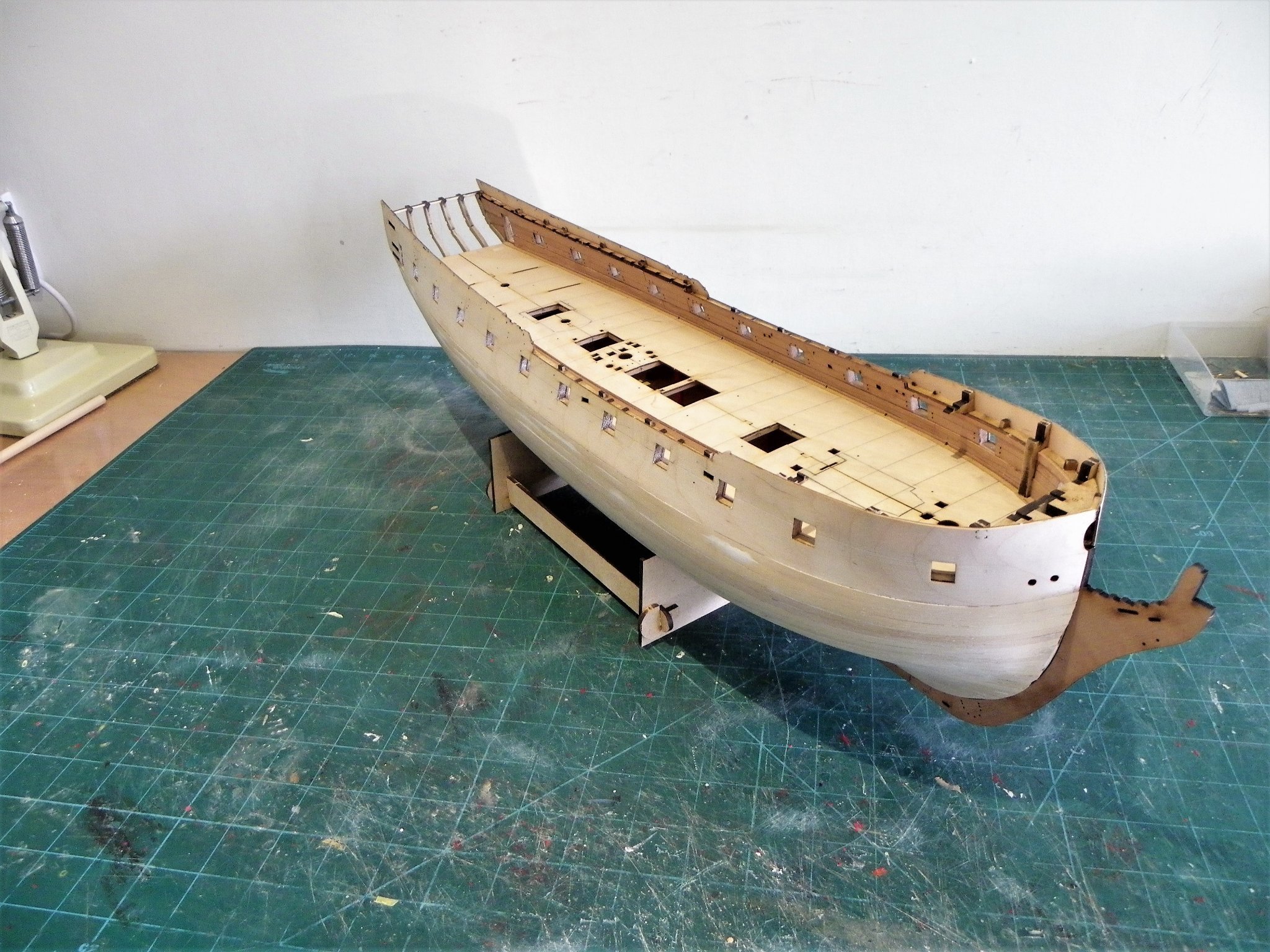
Post Twenty-six Sand fill and sand again. There are the usual (for me) strake ridges to attend to, I didn’t pay much attention to variations in plank thickness during planking, and there was a fair variation across the plank supply. Several of the planks were below 0.7mm and effectively unusable, being too soft to span the bulkheads without flexing. Only minimum filling was required in small areas. For this I use Deluxe Wonderfill a lightweight filler that dries quickly and sands well. It works well for small indentations and hollows in planking runs. 0742(2) I take photos under harsh lighting to reveal irregularities, along with the blind feel test. At the point I think ‘That’ll do’ I take more photos and faff around some more. 0753 With the model on my desk I can compare with macro photos where areas need a little more attention. After a day of sanding, filling, and feeling, I reach the point of enough is enough and move onto the Pearwood keel, stem, and sternpost. The fit of the stern post to keel was excellent, but the stem to keel at the bow needed some fettlin’ to get a nice tight fit between keel and stem. This is important if the option to not paint the lower hull is to be retained. I didn’t need to mess with the stem piece, just clean the false keel up. Keeping the stem piece hard down against the keel piece proved quite tricky using pva. 0760(2) This is the only clamp that had sufficient bite to secure it in position until the glue grabbed. Might have proved easier to use cyano for this joint. 0770 0772 At the stern area I have reduced the planks to a feather edge where they meet the stern post, not difficult with a soft wood like Lime. 0779 0777 The white filler generally indicates where the planking strip was undersize in thickness. 0780(2) 0800 0789(2) 0786 0791(2) 0790(2) After eight weeks work, I have the basic hull completed, and something that is recognisable as a bijou Frigate. Moving on… B.E. 20/10/21
.thumb.JPG.c7e571f6c18f377c4bbf05d4c1766bec.JPG)

.thumb.JPG.165658ce83dfa5446eeb1c3f599ffc0b.JPG)

.thumb.JPG.a25f743aaeb6e3fddc5d50dd4bb11aad.JPG)

.thumb.JPG.25806fe5082501893eb43e23c3b89e56.JPG)
.thumb.JPG.4255d7f55f0d738f1f51bd82c7eedffa.JPG)

.thumb.JPG.18cb555ecda21aa91d3cc293ee0fdb91.JPG)

- 857 replies
-
- 23
-
-
-
- Sphinx
- Vanguard Models
- (and 1 more)
-
Thank you, David, I completed the coppering in August 2011, and the model was cased in 2017 on completion. It is a slow process, I tried to get a photo through the glass but couldn't get a decent representation, with reflections etc. B.E.
- 310 replies
-
- 1
-
-
- Diana
- Caldercraft
- (and 1 more)
-
Nice work dunnock, she's looking very impressive. I'm a big fan of the OM boxwood I first used it on my Pegasus build and it sits very well on Diana. I also left the copper to age naturally and now after around 8 years is developing a subtle brown patina. Regards, B.E.
- 310 replies
-
- 1
-
-
- Diana
- Caldercraft
- (and 1 more)
-
The channels are not there to support the shrouds, simply to spread the angle for better support of the masts. The deadeyes are secured by the preventer plates and chains and sit in slots along the outer edge of the channels, usually covered by a board. The channels are not subject to the upward stresses one might think. B.E.
-
these photos often reveal something I never saw even at workshop close I then feel a need to go back and correct, if I can find them without the photo 😊 Ain't it the truth, I do it all the time, something of the masochist in me. 😀 B.E.
-
Looks like you're off to a good start, Bug, cutting a rabbet along the keel and up the stem pays dividends later .👍 B.E.
- 419 replies
-
- 4
-
-
- Victory Models
- Pegasus
- (and 2 more)
-
Nicely done Glenn, Looks good even under macro, a testament to your care and attention. B.E.

.JPG.58df4d4f7e0488b26a8ba98194ed352b.JPG)
.JPG.9303560e2a5cdba419c27aa42d631587.JPG)
.JPG.ffd2c2c9da0d35728d2a07b9a0e8c4b0.JPG)
.JPG.3665b4ed5890a5400cae5f9ea8727f28.JPG)
.JPG.73317c31a8d7f459b31a47e872c71cec.JPG)
.JPG.5f6d1de828b5344974e1a9e68b250892.JPG)
.JPG.8c0d3541763e5bd39373a57bd9939fcf.JPG)
.JPG.3ae4b7d0927733b2e7f0f31e1cba2290.JPG)


.JPG.88b3e848b9f9da0de81652a1a9fe08d6.JPG)
.JPG.e24668e7a6a38bb272be208a9ccb0278.JPG)
.JPG.ac33977983f8fc479026b06d9b31f4e9.JPG)
.JPG.732bb4150dc97d72c9cbfd91a81bf63c.JPG)


.JPG.14589b58aa9e79bb5b3b259ae321630b.JPG)
.JPG.035579bae0c12866211657f4c388b720.JPG)
.JPG.8cf1240cfcec3aaec0f15ef9942fcf28.JPG)

.JPG.2376628961ebc892f85ecaf752332320.JPG)

.JPG.8b976a91621f15115be933f0fd1832ac.JPG)
.JPG.b7640106535f60ff71fd37e37f151f7e.JPG)