
.JPG.ca33079f5815b861e67b9c2cccd37982.JPG)

Blue Ensign
-
Posts
4,572 -
Joined
-
Last visited
Content Type
Profiles
Forums
Gallery
Events
Everything posted by Blue Ensign
-
 Your perseverance is paying off bug, and you're very brave drilling thro' the strake to the deck for the scuppers, something I passed on, I had little confidence I would hit the right spot. B.E.
- 419 replies
-
- 3
-

-
- Victory Models
- Pegasus
- (and 2 more)
-
Thank you James, that's reassuring to know, I am very much impressed by the box art photos of your build which clearly show the plank lines. I do hope I can replicate the effect; I am hand painting so I think fine coats are the order of the day.🤞 B.E.
- 857 replies
-
- 4
-
-
- Sphinx
- Vanguard Models
- (and 1 more)
-
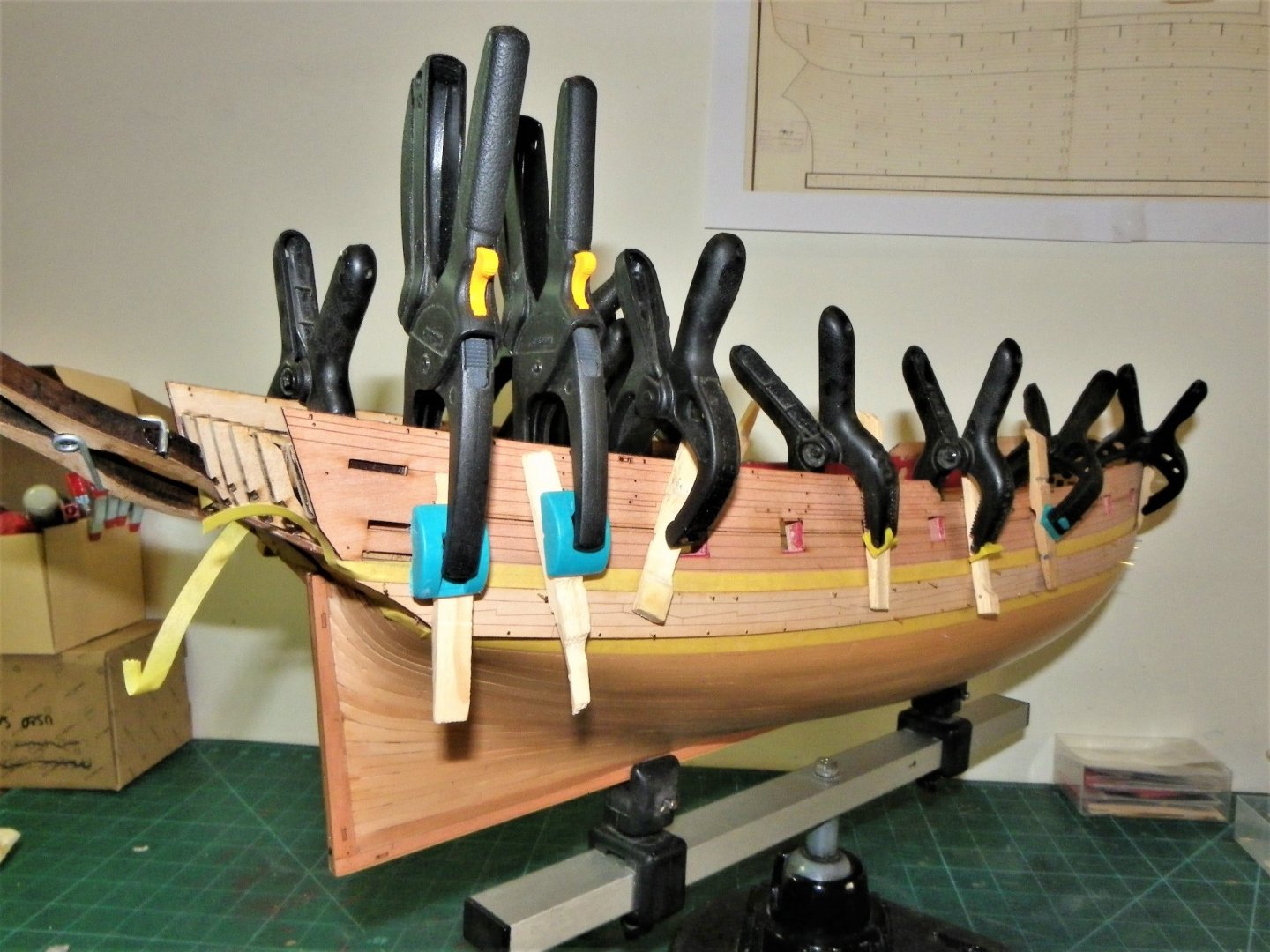
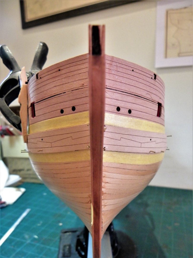
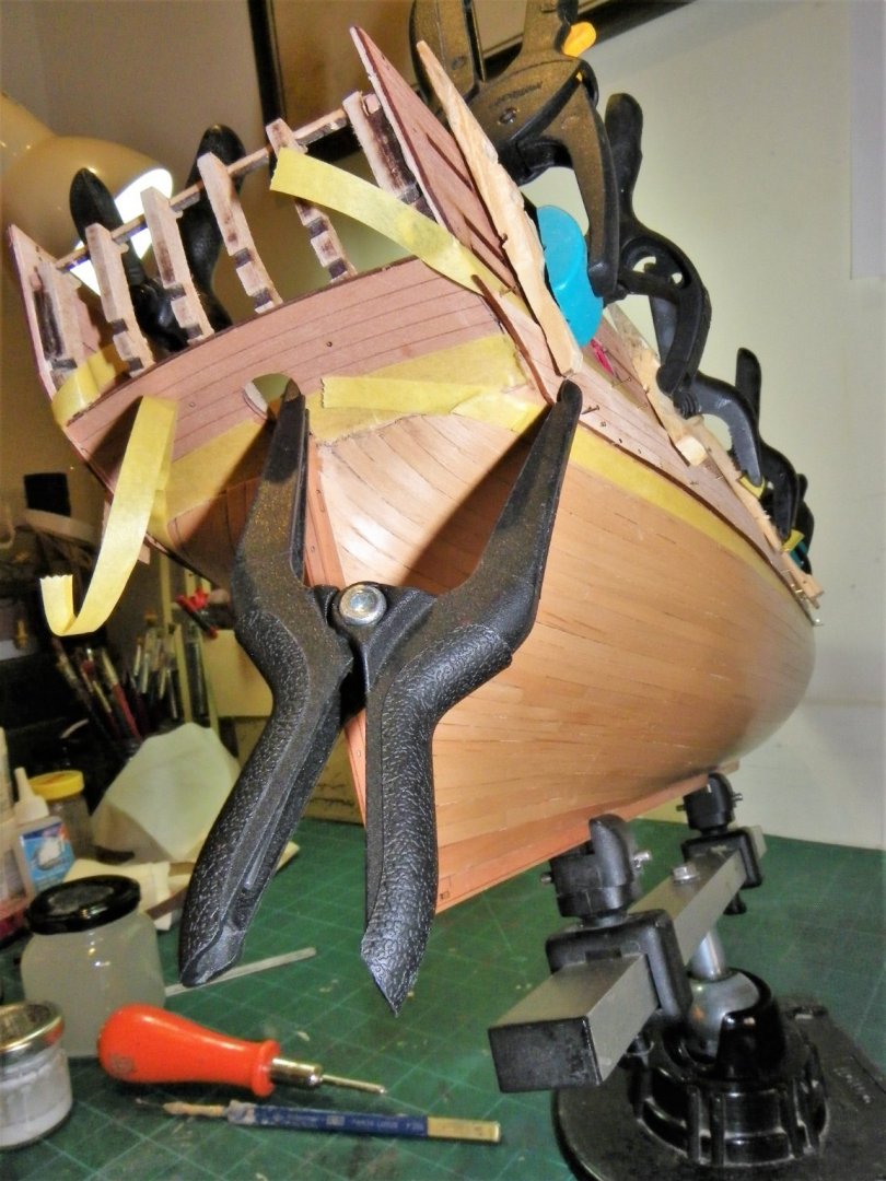
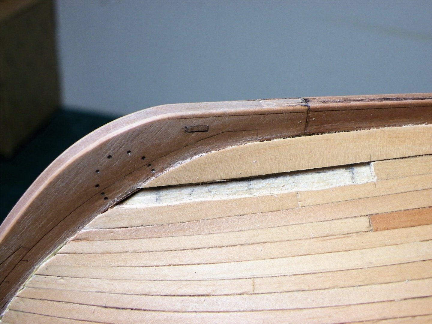
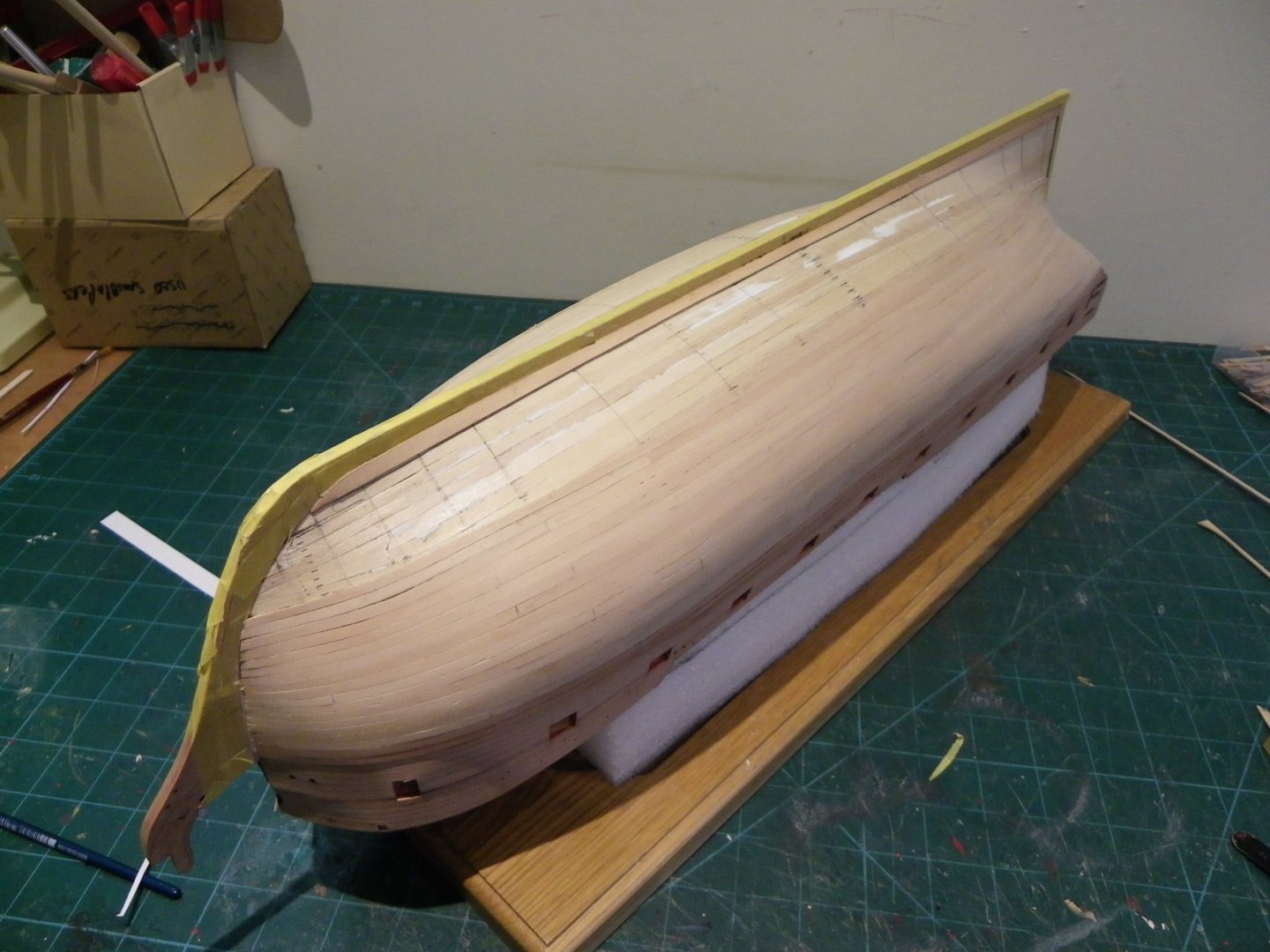
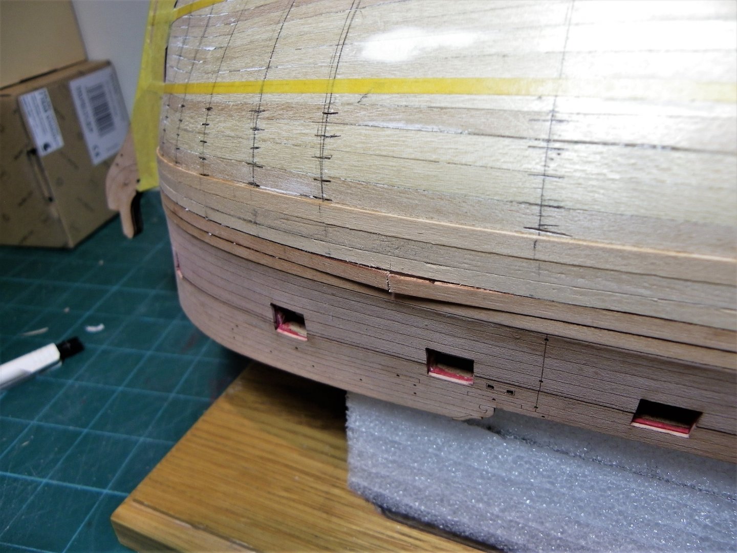
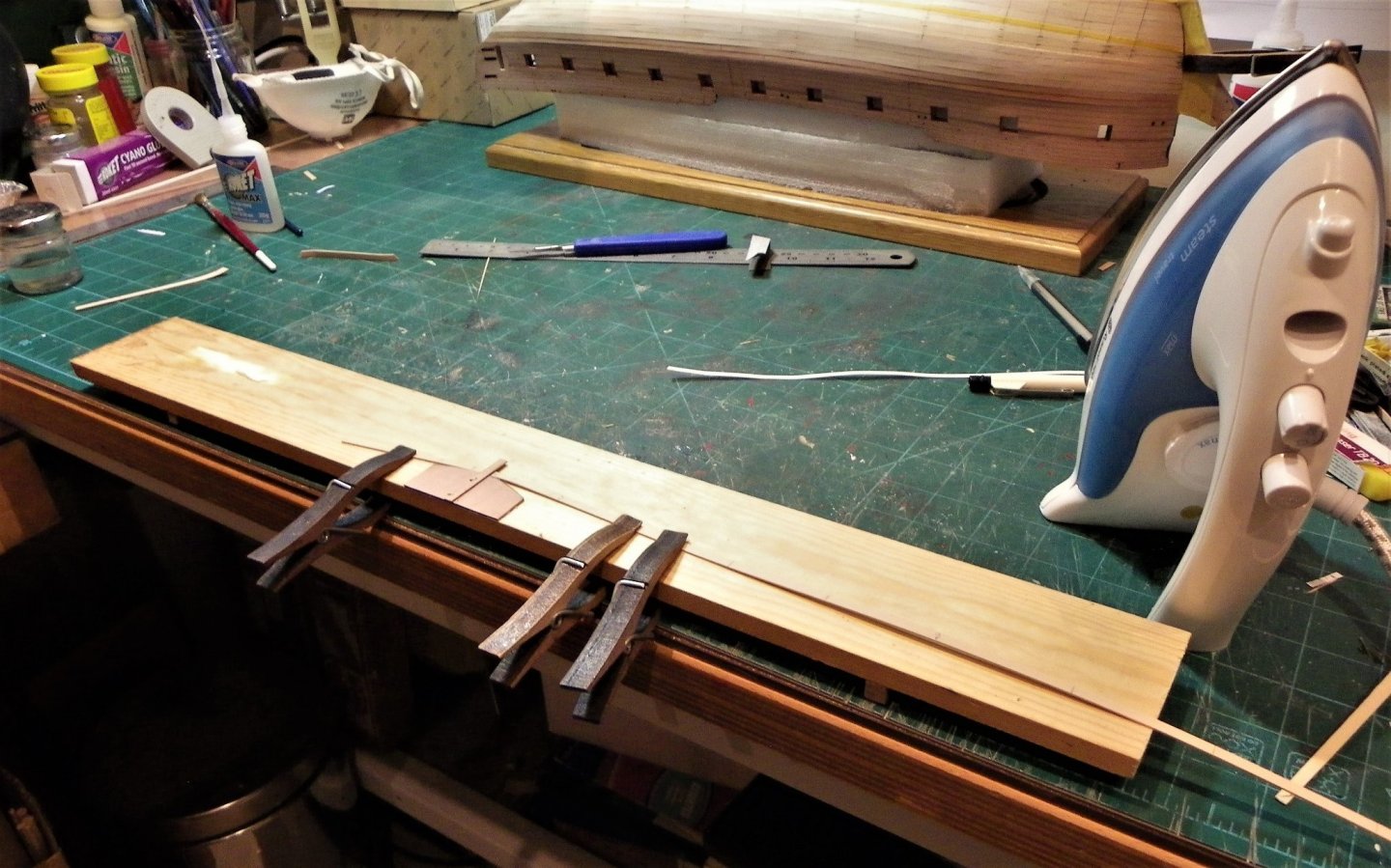
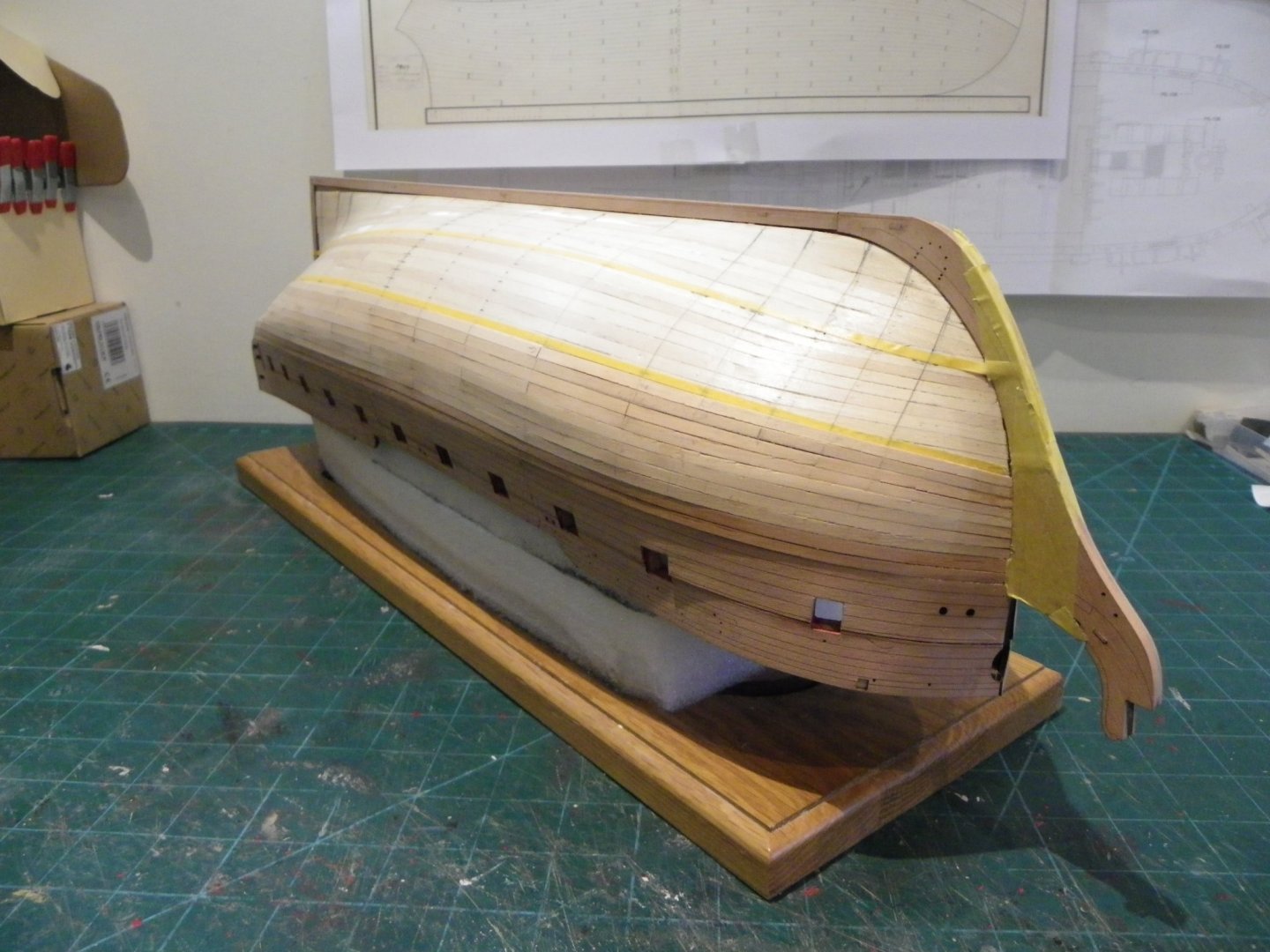
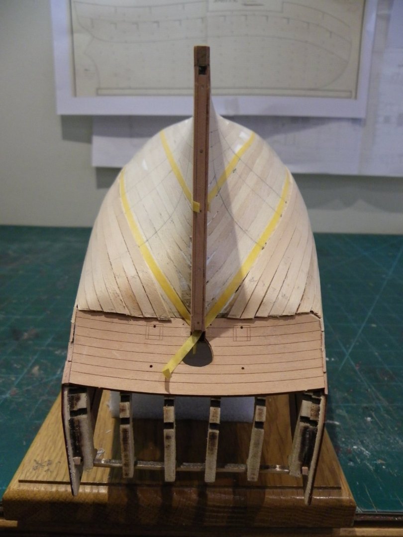
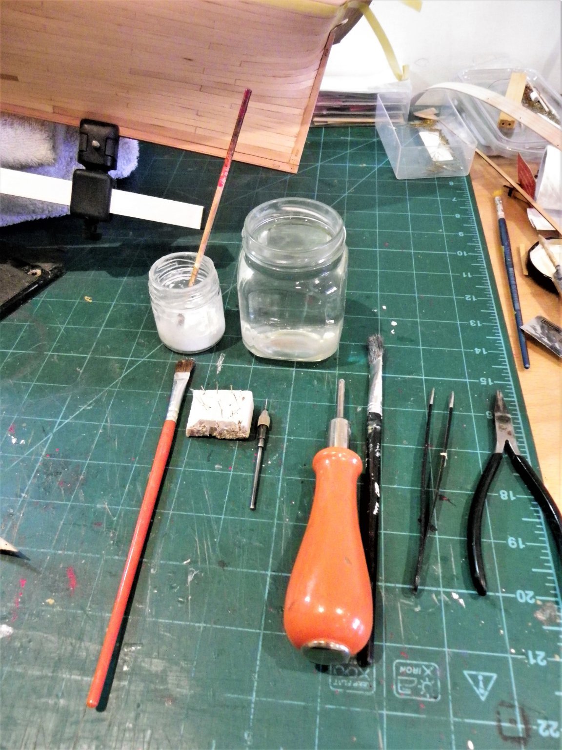
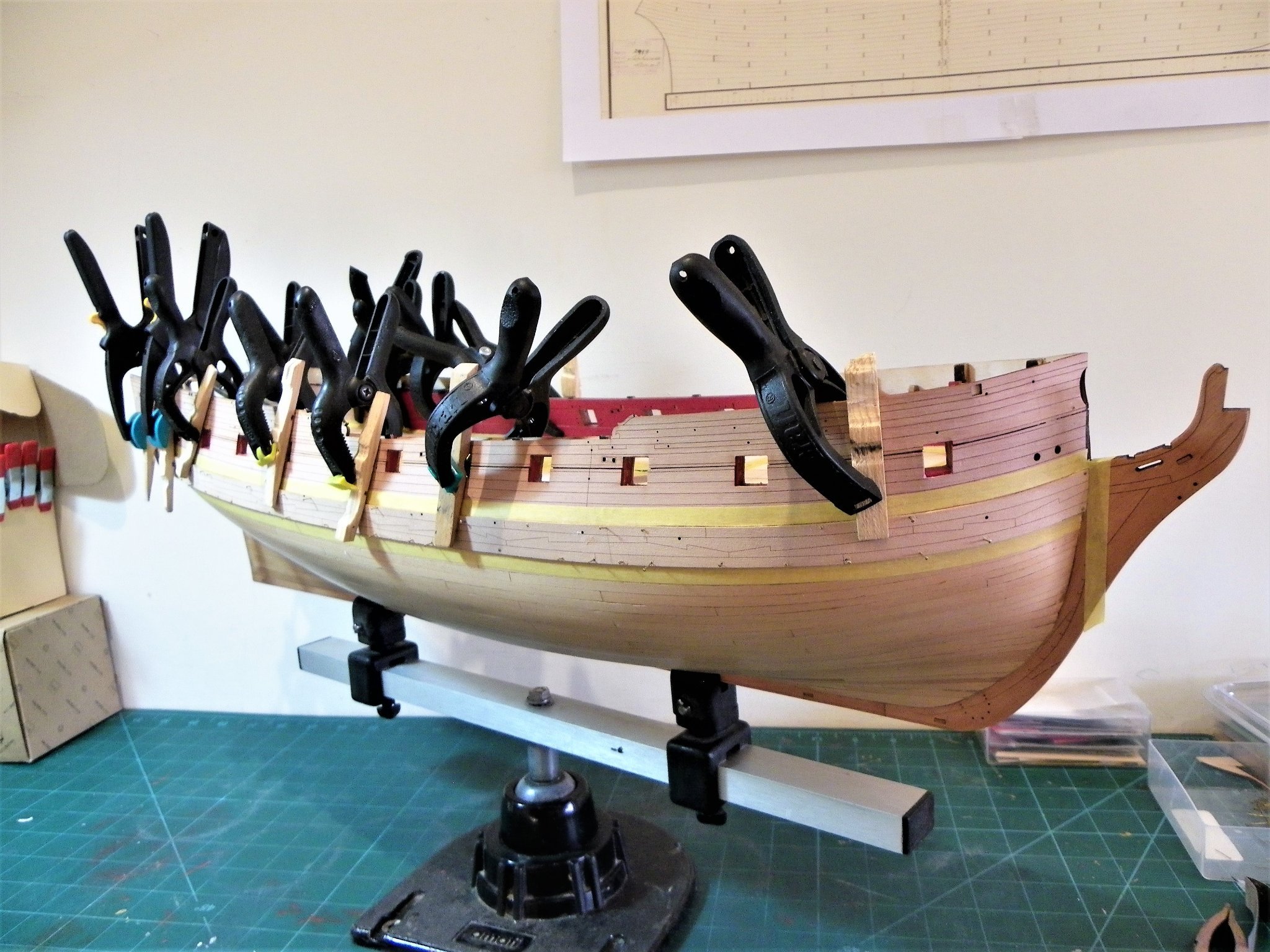
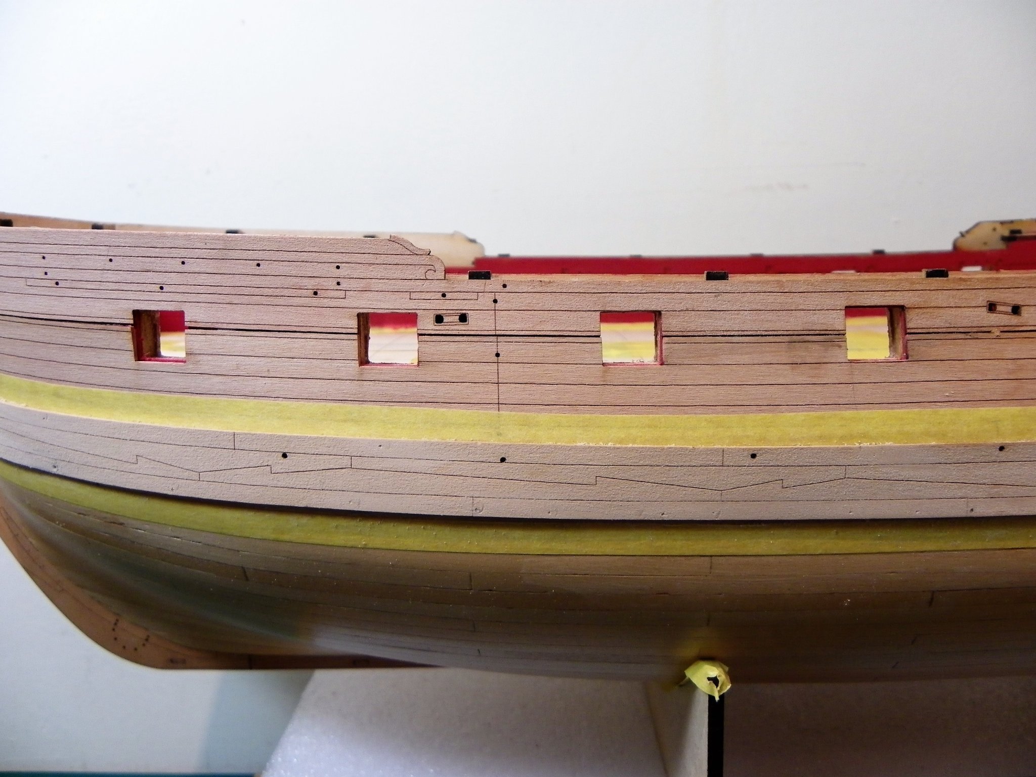
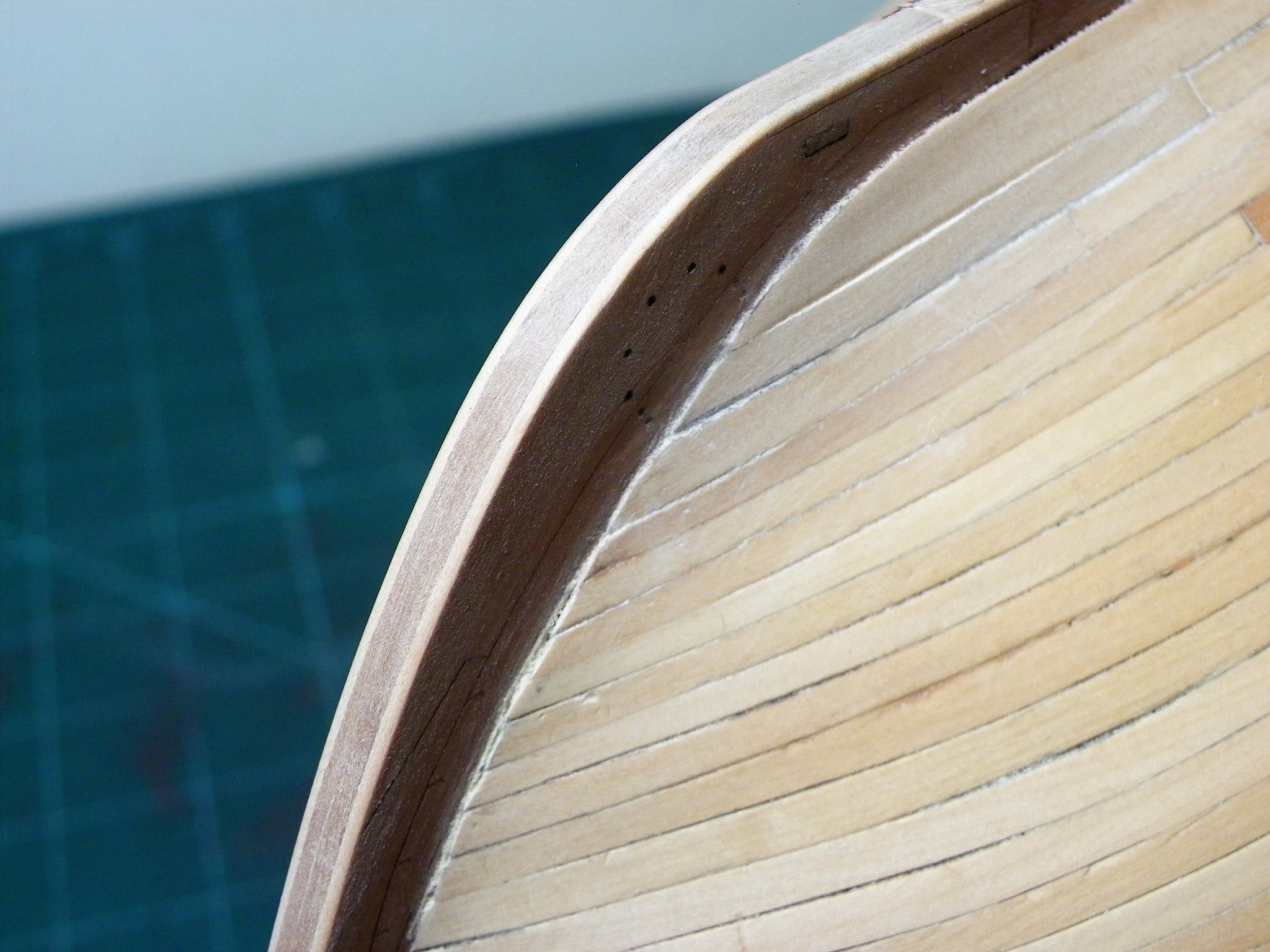
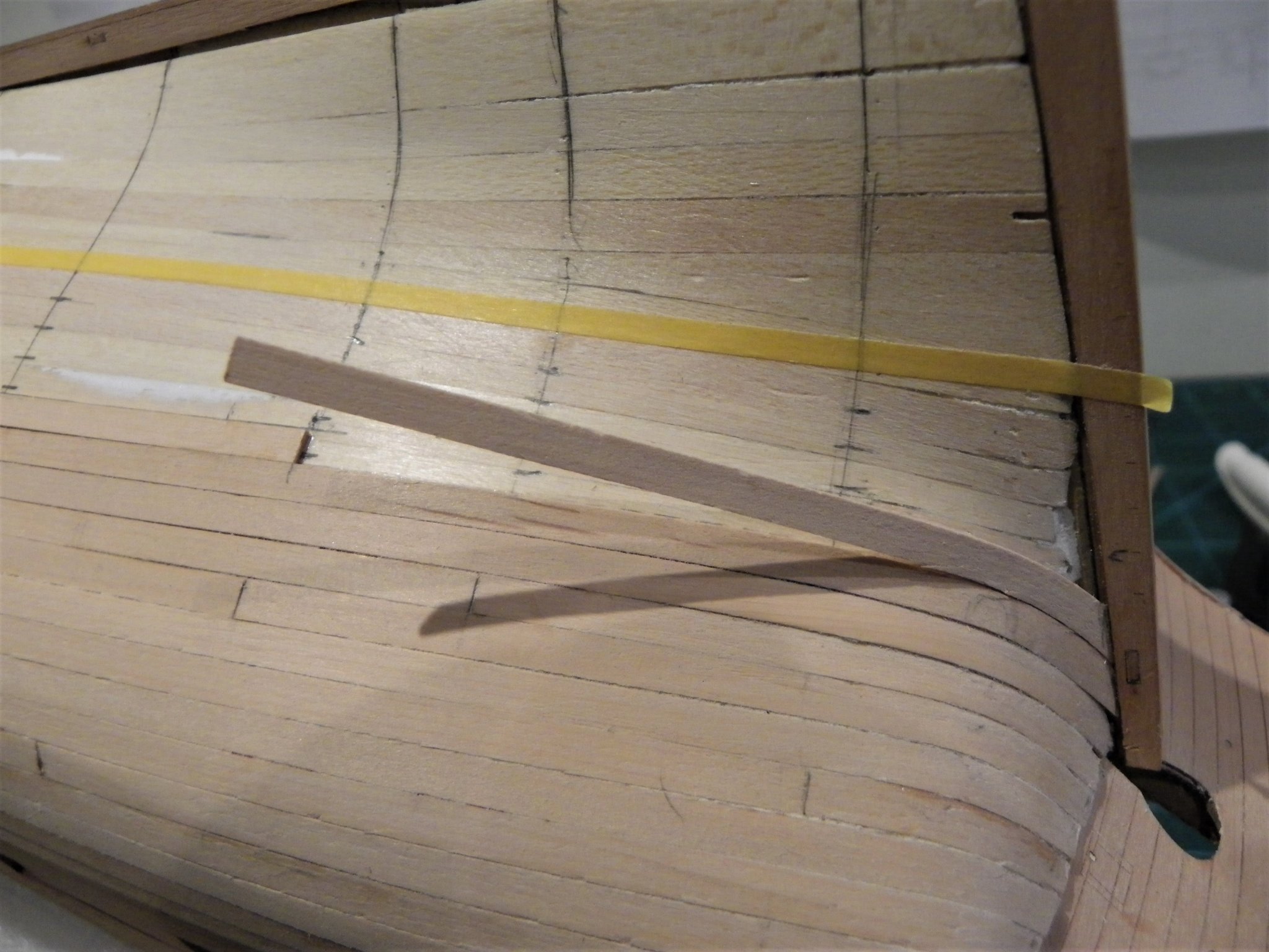
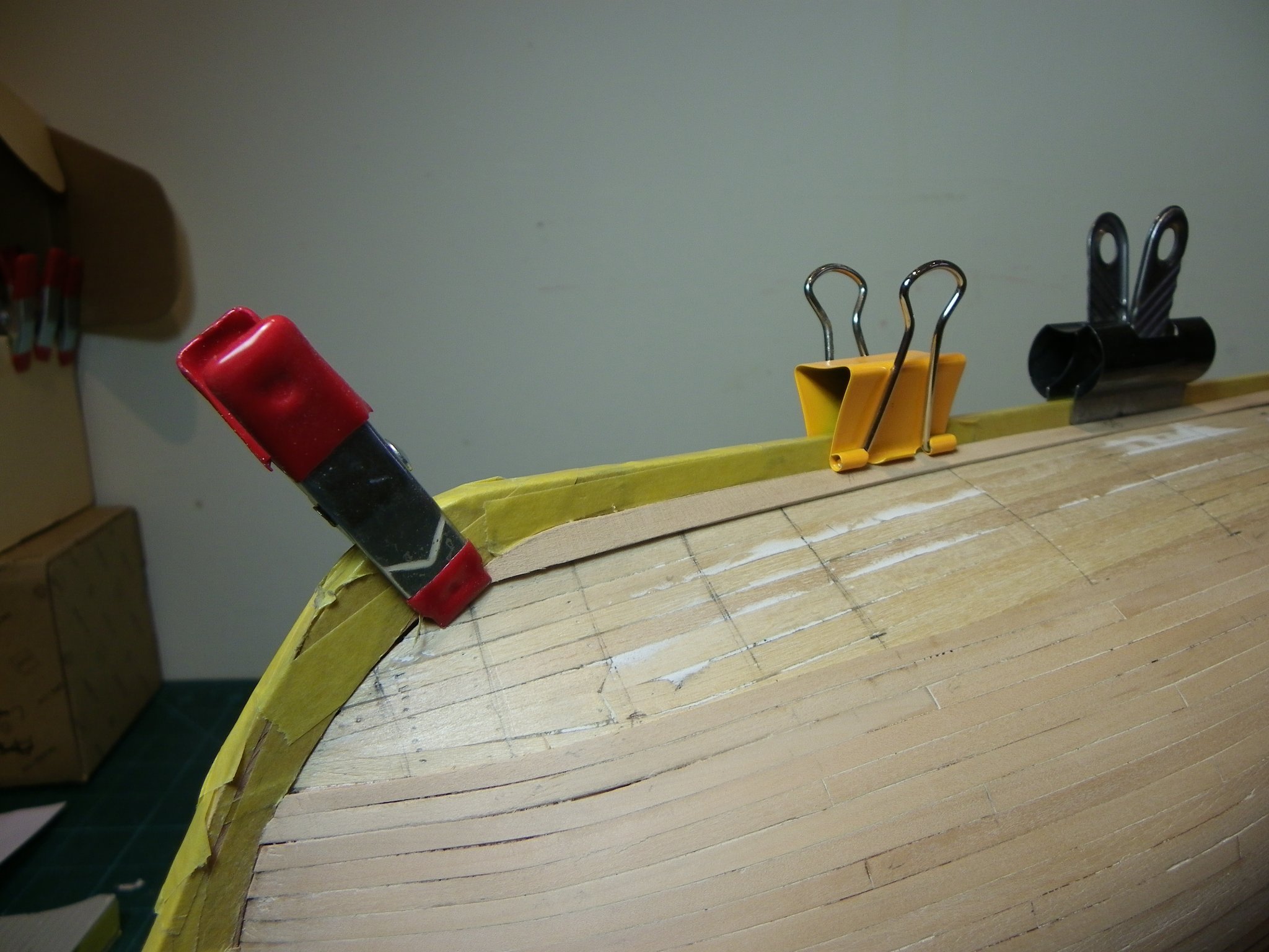
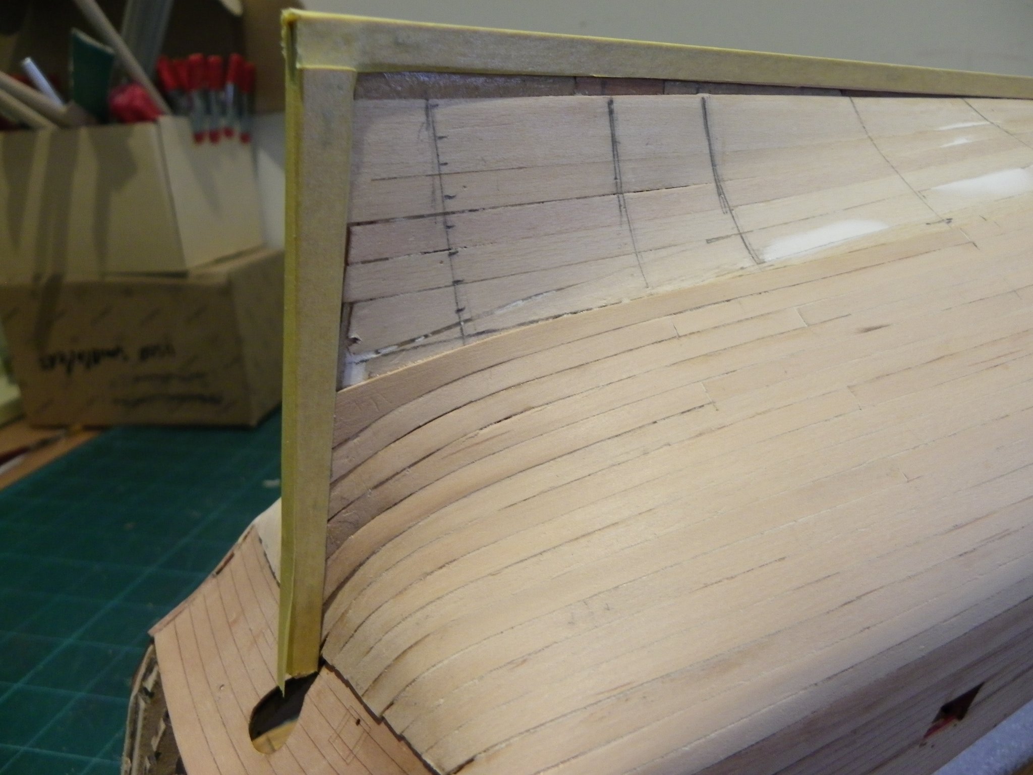
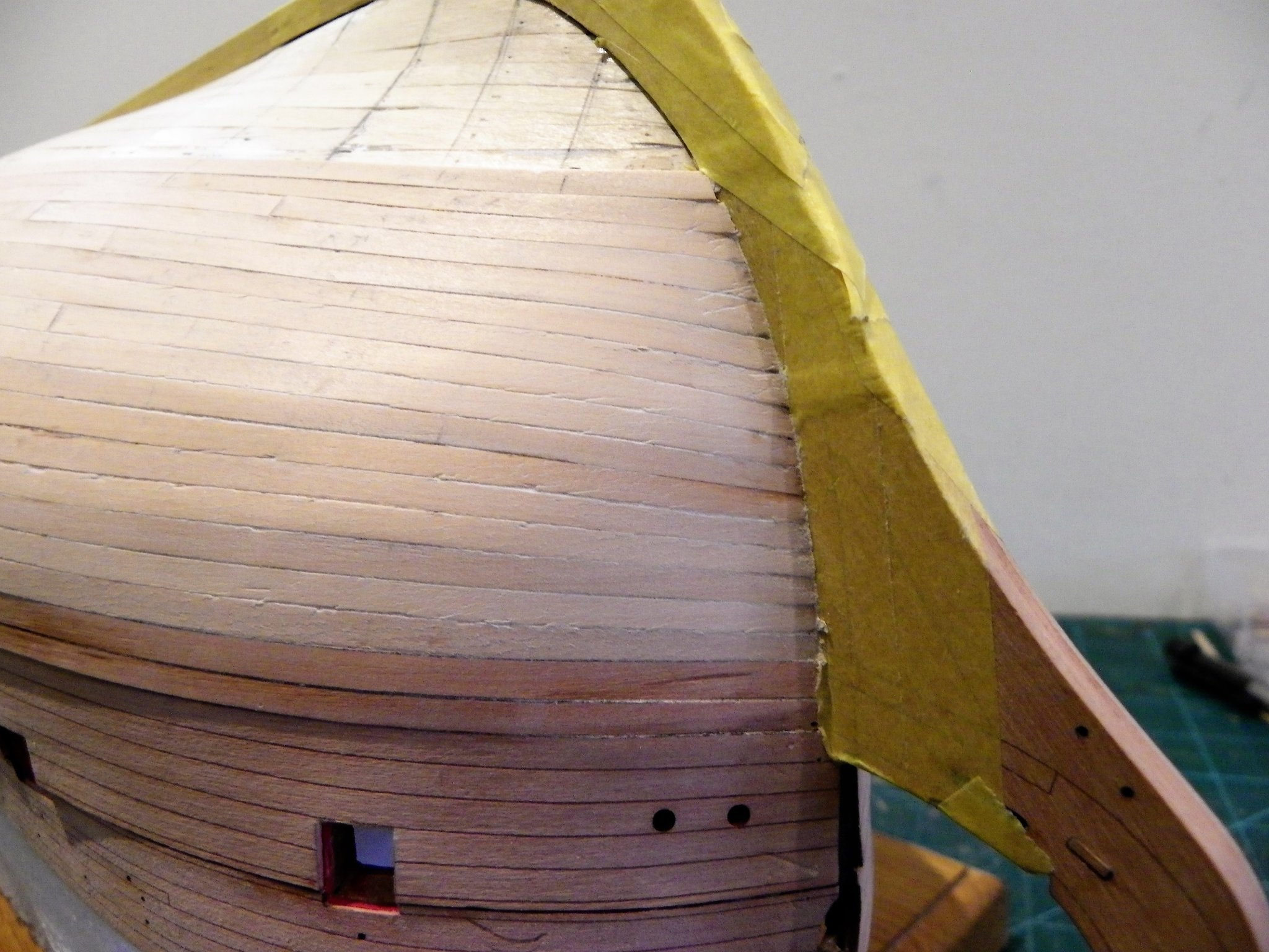
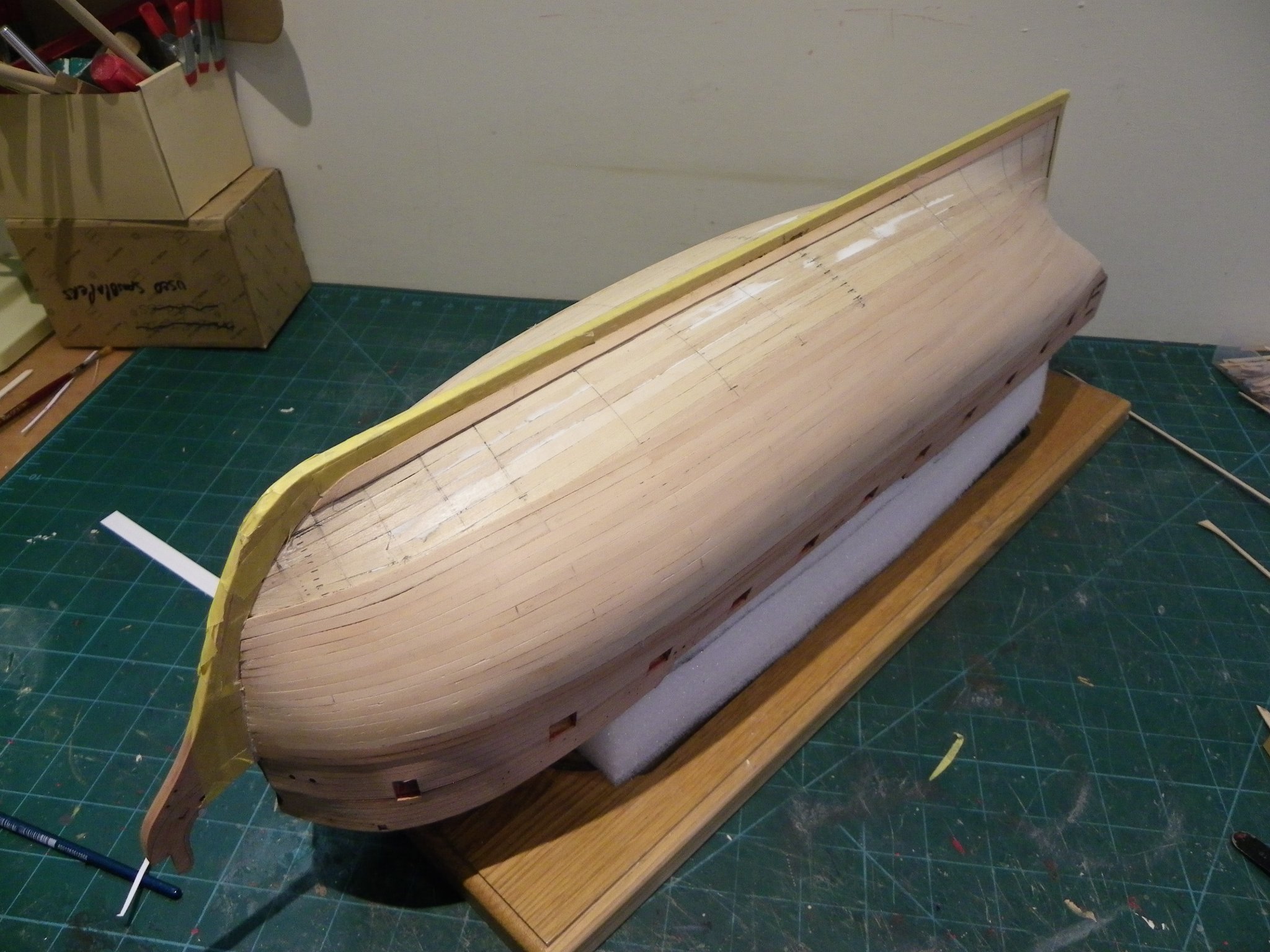
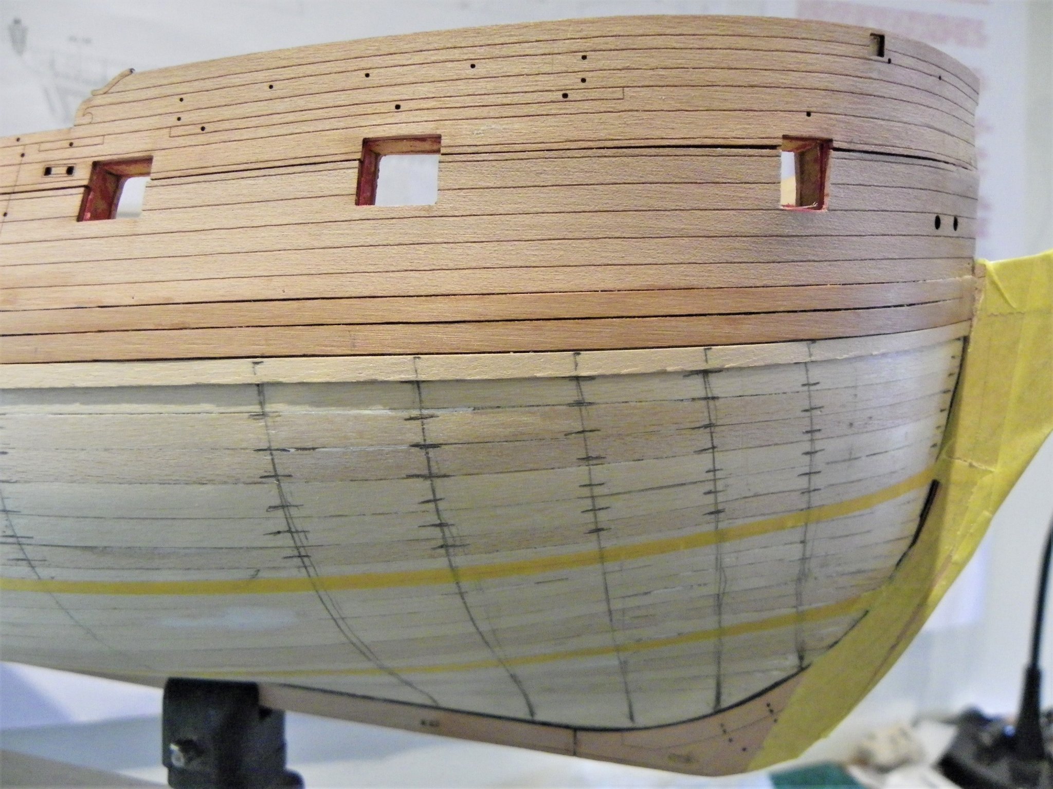
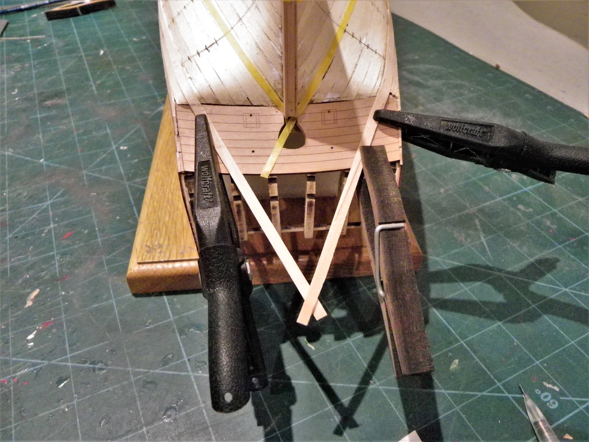
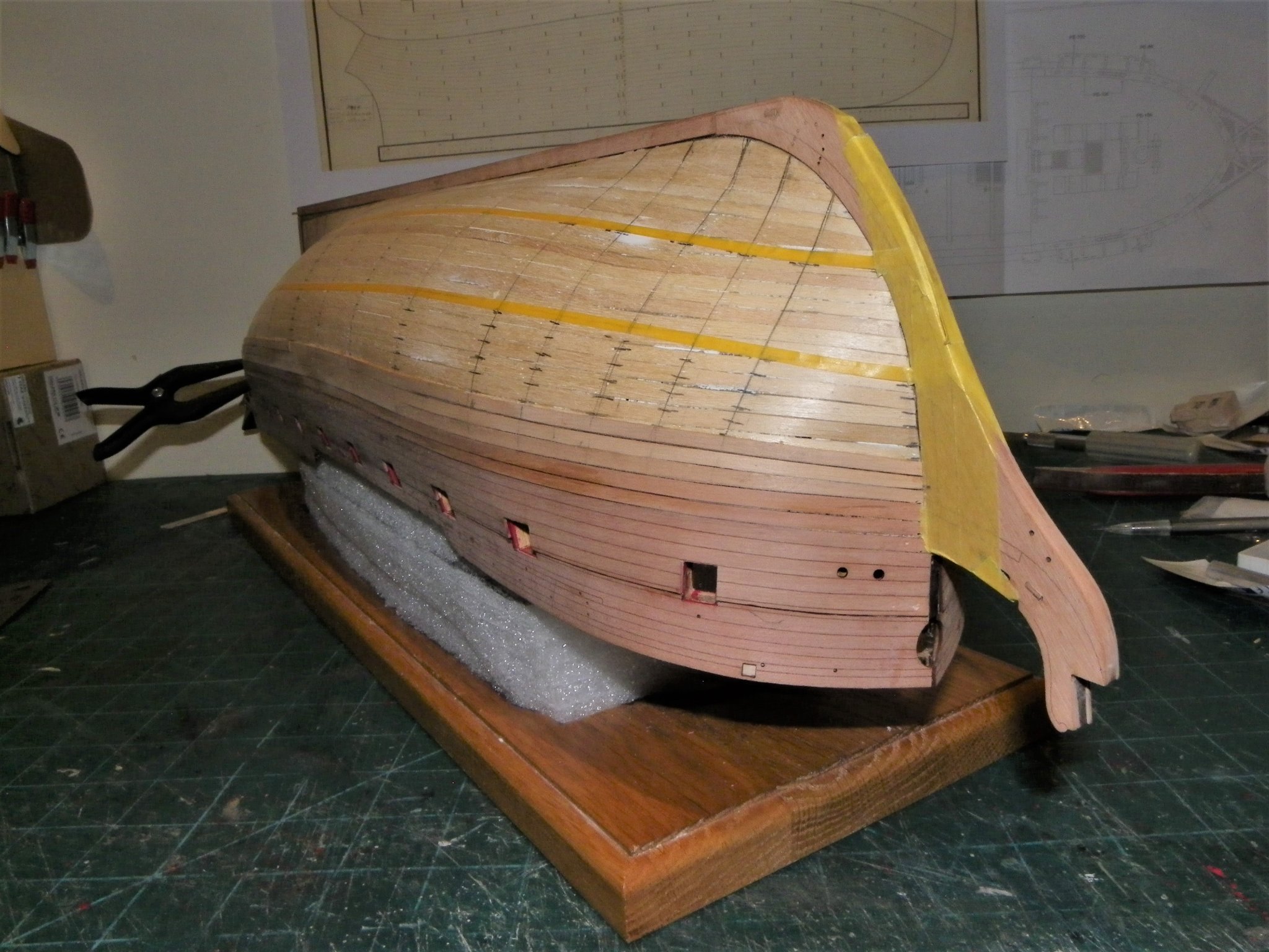
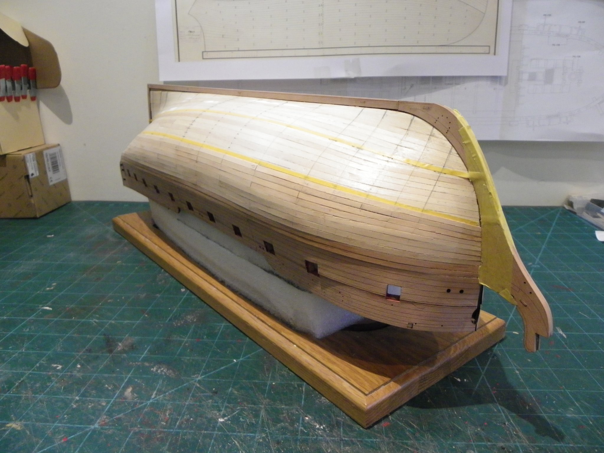
Post Forty-two Fixing the wales. It may be thought that this is a fairly straightforward procedure, given the marked lines of fitting on the hull coupled with pre-formed wales, there is no working out for yourself that critical wale position. I considered constructing my own t&b wales as I had with Pegasus, but the thought lasted but a nano second. 1367(2) The kit supplied pieces are nicely engraved with the Top and Butt planking lines, and it would be a pity not to use them. The trick will be colouring it without covering up the plank lines. I followed the given procedure and used fine pins liberally to secure the wale strip against the hull for the shape forming process. The hull was then left overnight to fully dry out. Probably due my increasing decrepitude I didn’t find fitting the wales the easiest of tasks. They have to be correctly positioned, and held in place while pins are inserted to hold them fast, all before the pva starts to set. Preparation is the key. I have the fine pins inserted in a balsa block for quick access, a micro pinvise, a jar of water and brush to clean off any pva overspill, and the pin pusher close to hand. 1376 The pva is decanted into a small jar and is slightly diluted. It is applied by brush as the wale is fixed along the hull. The hull is secured in the keel clamp, better to see the required line and piled towels are used on the opposite side to support the hull against the pressure of the pin pusher. 1377(2) Tamiya tape is applied above and below the wale position to mark the glue line and reduce the risk of overspill marks. The forward end of the wale strips needs a slight bevel to fit tight against the stem. 1381 On my build the wales required a lot of pins to hold it firmly against the lower edge and additional pinning and clamping on the upper edge. 1387 1388 A prime objective is to get the wales looking symmetrical at the bow. The stern area is the tricky part where the aftermost lower edge needs to curve downwards laterally very slightly, to meet the round of the hull. 1393 I was able to clamp this by using a pin head on the wale and the rudder port as anchor points. The set-up was then left overnight for the glue to fully cure. 1402(2) 1405(2) 1408(2) 1410(2) Before I move on I need to resolve a puzzling issue with the pre-drilled scuppers, of which there are six. 1412 The forward two are offline against each other and the preceding four, which run along the top edge of the wale. This is not reflected on the plans where they all run along the top edge of the wale. This in itself is an issue as they are too close to the top of the wale with no allowance for the flange that would surround them. I rather think they should exit thro’ the Black strake above the wale, which is how I will position them. The holes on the wale will be filled before painting. This is a small thing and overall the wales look good and surely save an awful lot of T&B cutting. B.E. 28/11/21
.thumb.JPG.a3de7927e4007f9541bcf5384cc0edd8.JPG)

.thumb.JPG.d87fad1bbc9bab01287cde10b9391e0f.JPG)

.thumb.JPG.83bb4ac55eb400b9e4e9ed4a44f41c88.JPG)
.thumb.JPG.d4d84220504ec2d77272b7d42969386f.JPG)
.thumb.JPG.b7469b3c24469b91d54f550b765f07b1.JPG)
.thumb.JPG.887db44c06cdf8db58b2b67b2ea580f8.JPG)

- 857 replies
-
- 24
-
-
- Sphinx
- Vanguard Models
- (and 1 more)
-
Nice work Chris. 👍 B.E.
-
Thank you Derek, Bug, and Ron, it's a great relief not to have to mark-in that waterline. @ Ron - had I thought it necessary to cover up planking deficiencies, which was a distinct possibility, I was thinking of coppering her. Sphinx was coppered in 1781 before the modifications to her ordnance in 1794. In that event I would be going for the flat brown old penny look rather than bright. I had also thought about a painted finish, in which case I had in mind 'Light Ivory' a shade in the Admiralty paint range. Still none of that has come to pass and I can move onto the wales, I too am curious how I'm going to handle them. 🤔 Regards, B.E.
- 857 replies
-
- 2
-
-
- Sphinx
- Vanguard Models
- (and 1 more)
-
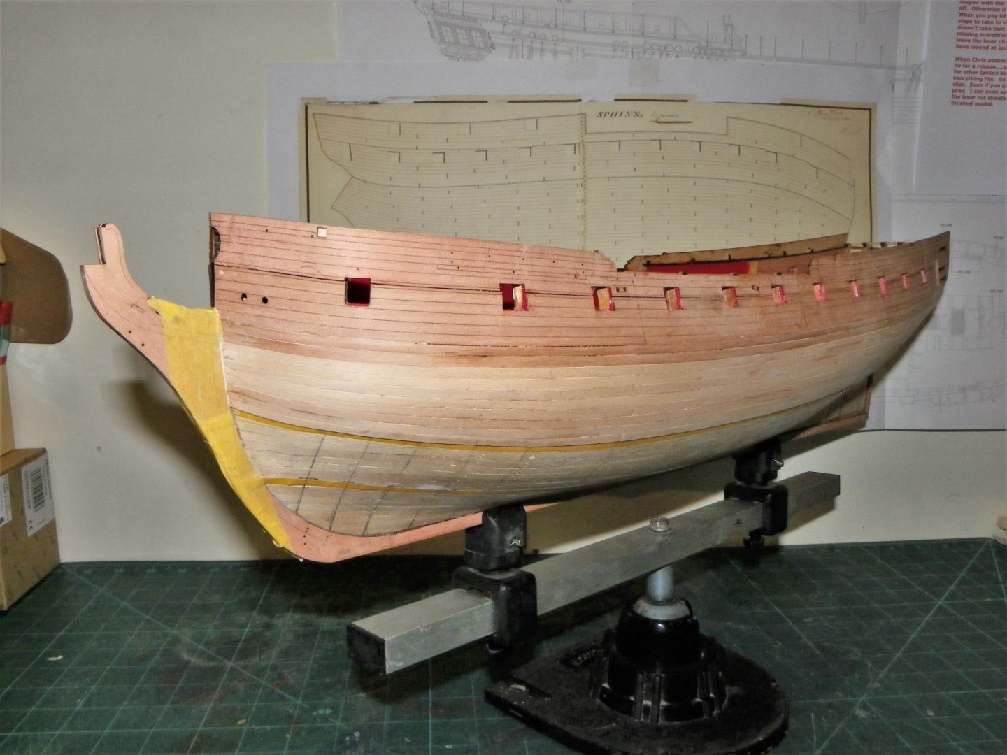
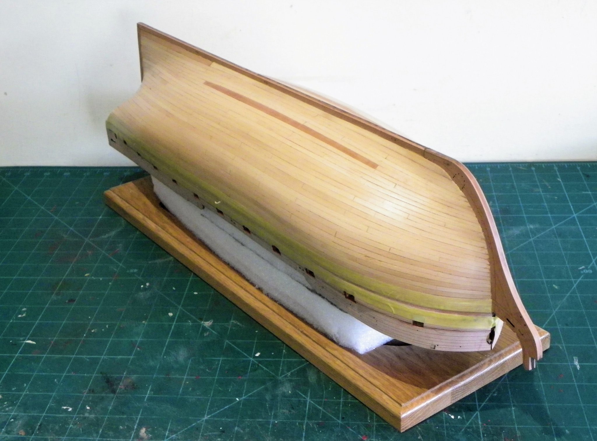
Thank you Jason and Glenn, and for the 'likes' Post Forty-one The moment of truth A coat of w-o-p is applied to see if the result is now good enough to leave the lower hull unpainted. On balance I think that it just about makes the grade. A further two coats are applied; the keel and stem areas are brushed with w-o-p and immediately wiped off with a clean rag as I move along. 1337(2) I do like the look of the knee of the head with its engraved constituent parts, the lines pop out once the w-o-p is applied. 1319 As a bonus, I avoid the troublesome task of marking the waterline, and I wasn’t really keen on that vast expanse of white paint anyway, at least not in relation to the Navy Board style of display I am seeking to achieve. 1317(2) 1330(2) 1323(2) 1315(2) 1333(2) 1331(2) 1347(2) 1329(2) I can't be sure that I won't indulge in a little further fiddling with it before the point of no return, but for now, I'll move onto the Wales. B.E. 26/11/21
.thumb.JPG.8a7bc8c415675e7164f3cdcffd546772.JPG)
.thumb.JPG.42396e452b561accda228e020c38c661.JPG)

.thumb.JPG.0fee895aef5e75509cad3a024c1bf6e7.JPG)
.thumb.JPG.47a634954848f38eb0c65bca354b2a5c.JPG)
.thumb.JPG.fe680052e13798a51a9dca5d0d967cf2.JPG)
.thumb.JPG.6f763ecfecabeb152921468dc48cf994.JPG)
.thumb.JPG.95d16ae1e194ce9de3cd3f25de5f258f.JPG)
.thumb.JPG.98a9ff4cff3809e408d6739efd2ec98a.JPG)
.thumb.JPG.4909725d555a813e8f9b3251637422d9.JPG)
- 857 replies
-
- 26
-
-
- Sphinx
- Vanguard Models
- (and 1 more)
-
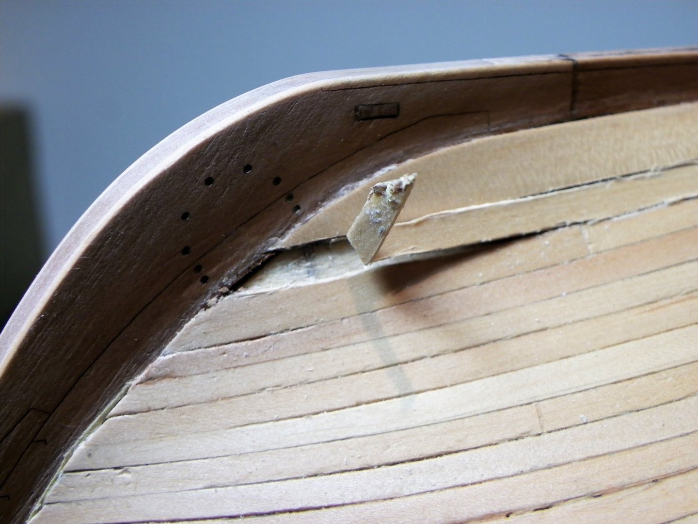
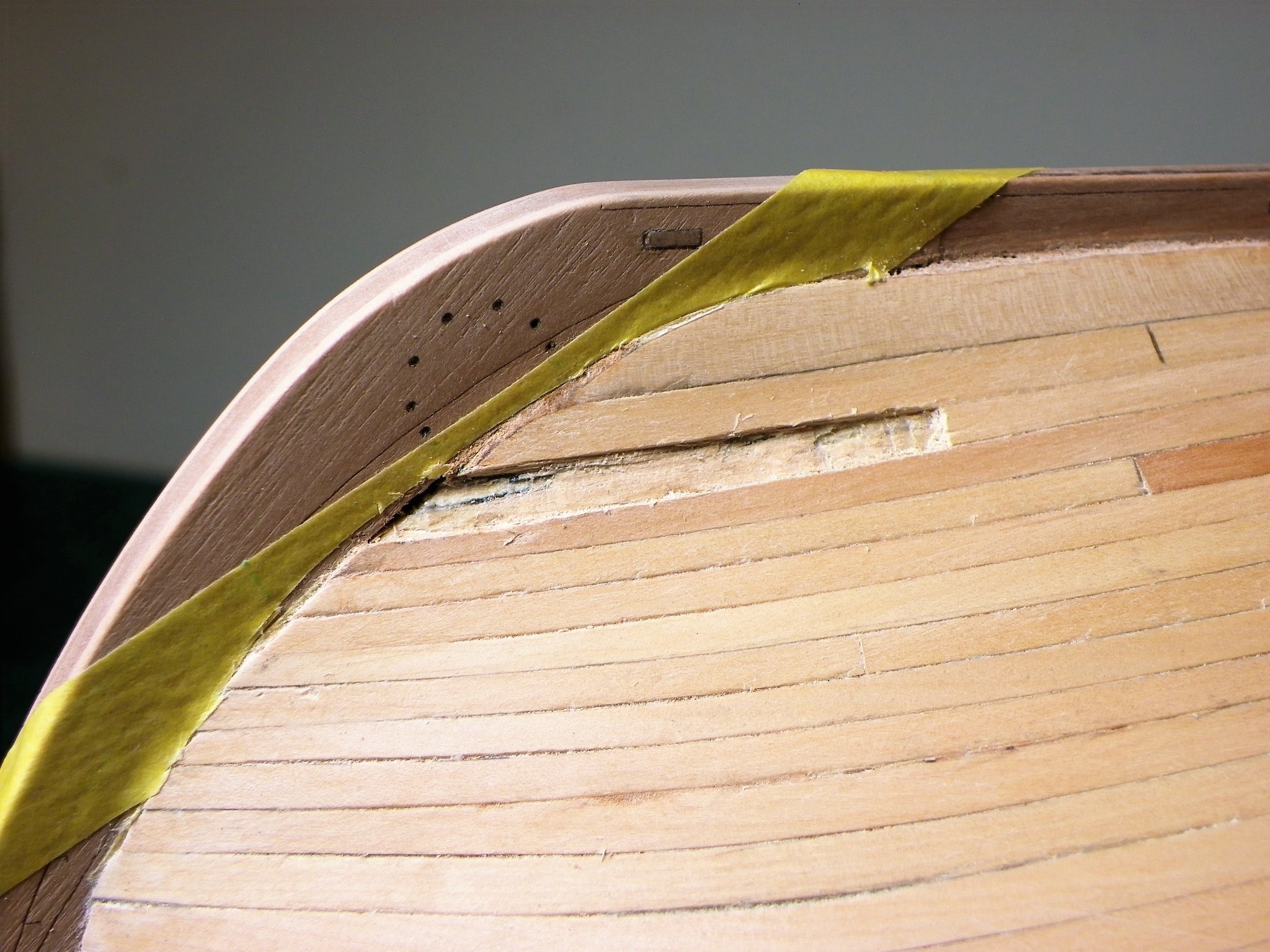
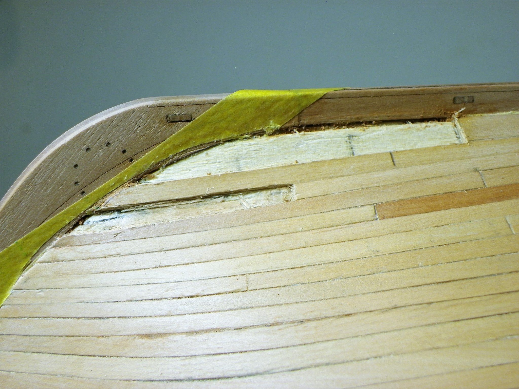
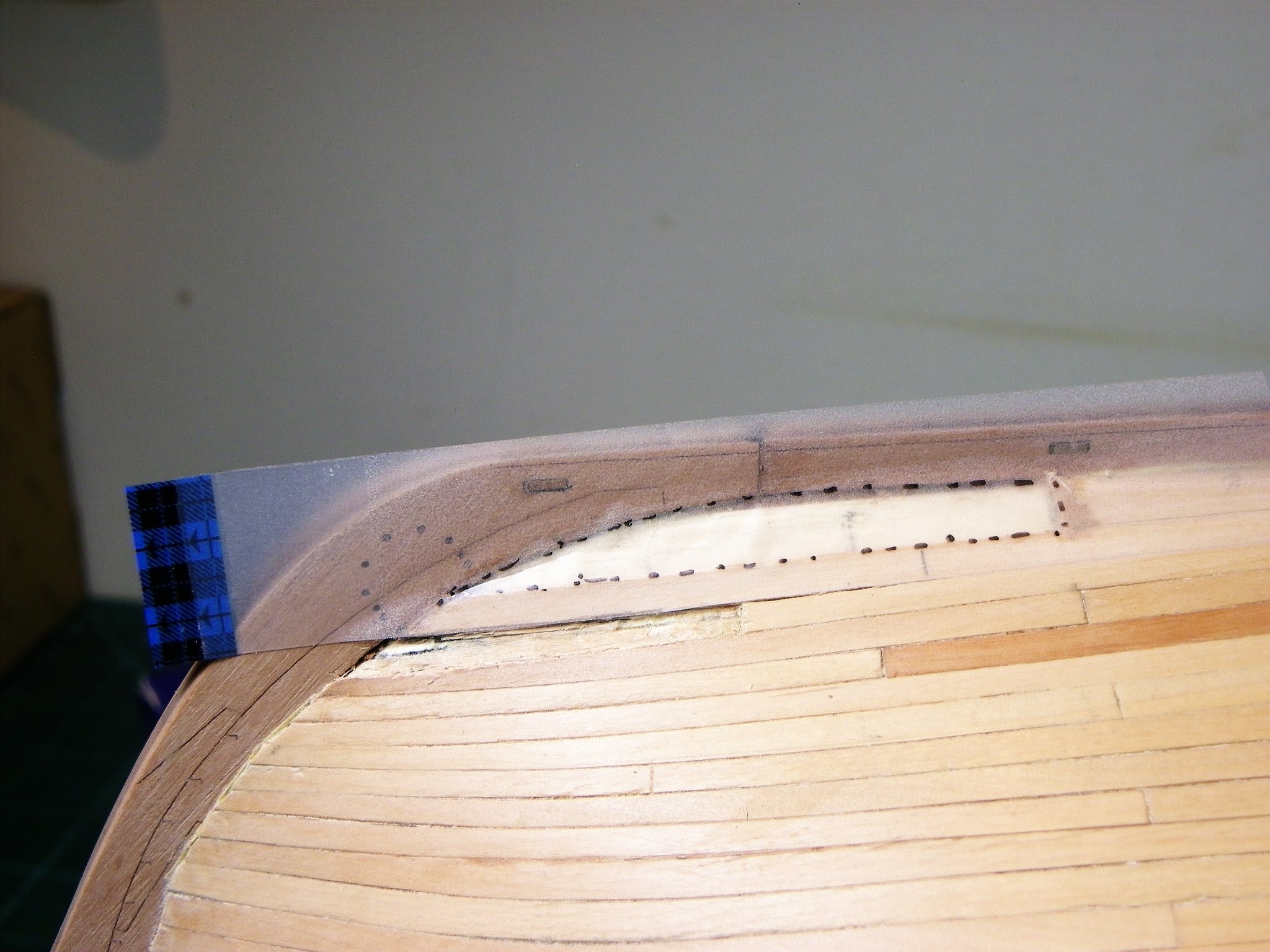
Thank you Rusty, but things don't always go well as you will see below. 🙄 Post Forty A step backwards. Just as I was getting ready to finish the hull my eye was drawn to the forward end of the Garboard strake on the Port side and the two adjacent planks to it. The finish against the stem wasn’t good enough and no minor filling however well matched would mask the deficiency. The problem was caused by the protective tape on the stem overlapping the inner edge resulting in a fractionally short fit against the stem. Nothing for it but to remove sections of planking and replace. 1297 1298 1300 Marking a template for the Garboard replacement. 1308 1309 The removals went better than I could have hoped greatly assisted by Swann-morton chisel blades, and carefully applied Acetone to assist with ca de-bond. 1306(2) These chisel blades are perfectly sized for delicate work and very sharp. 1313 A mornings work and the issue is resolved. There is very little on a wooden model that can’t be rectified and where it is possible it is always a good idea to go back, otherwise these things tend to catch your eye forever. B.E. 25/11/21


.thumb.JPG.d8d5907d62b2ca83c39b56a4dc1b7ab8.JPG)

- 857 replies
-
- 30
-
-
- Sphinx
- Vanguard Models
- (and 1 more)
-
It seems to me that the area you are now approaching is all about mouldings and mitres. To look anywhere near good they need to line up so a lot of trial pinning and fitting and jumping ahead to check out stage 310 is probably necessary to avoid any nasty surprises. B.E.
- 505 replies
-
- 6
-
-
- vanguard models
- Sphinx
- (and 1 more)
-
Hi Dave, you asked. I also do not know the size of this flagstaff in either width or height or any other information other than the lengths of other flagstaffs carried on other masts which just confuses me somewhat. Hope this makes sense. My last build did not carry a flagstaff, the flags were just carried on rigging up to the top mizzen mast. Best regards Dave. The AotS on Endeavour, by KH Marquardt describes the Ensign Staff being commonly one-third of the height of the Mainmast above the Taffrail. The given mainmast height is 69' 4" which equates to 23' (Plus the Taffrail height) This is probably not far off as in the ffm book on sixth rate sloops, David Antscherl gives the Ensign height as 24' with a base diameter of 4½”, tapering somewhat to the Truck which has a diameter of three times the top of the staff. This should give you enough to fashion one for your model. Regards, B.E.
-
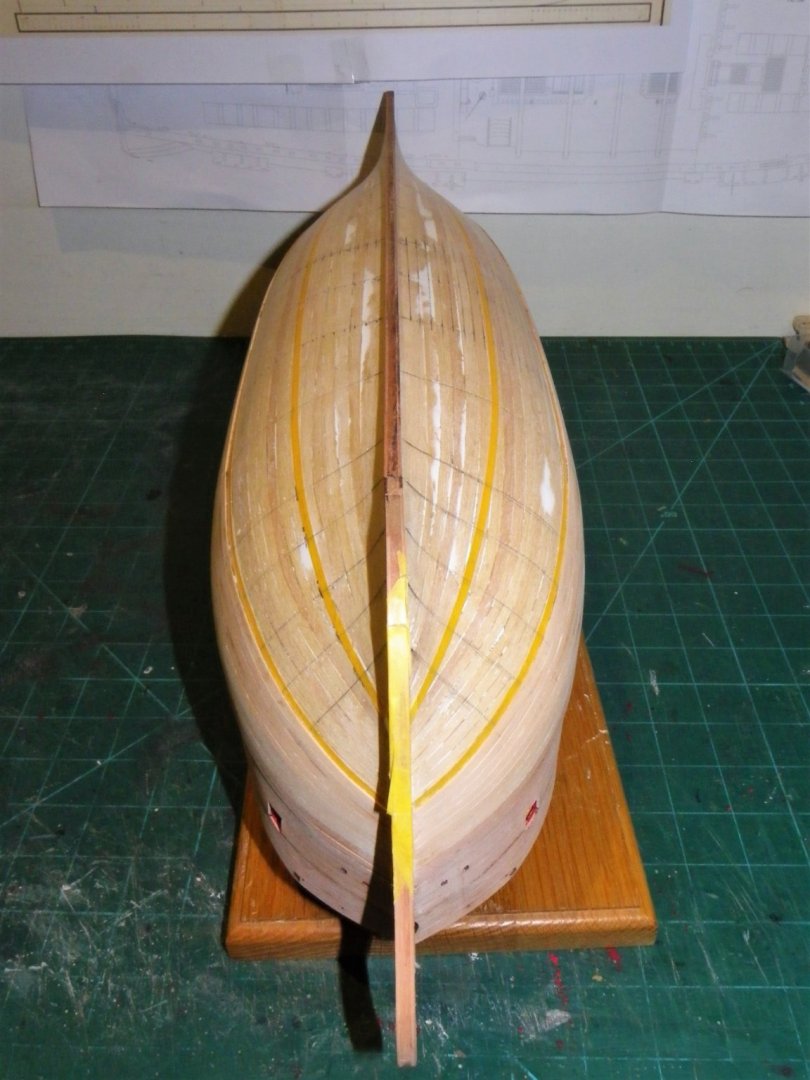
Post Thirty-nine Sanding and finishing the hull. The hull needed only a light sanding and minor plank line gaps were filled with a dilute pva/pear dust mix. My approach is to use a syringe filled with dilute pva to run along the seams, sprinkle pearwood dust over the line and gently brush it across the line before sanding to consolidate and smooth the mix. The Pearwood sands up beautifully, and even after a fairly short time there is a silky smooth feel to the hull. These pics were taken after an hour or so and were taken to highlight any further attention required. 1280(2) 1279(2) 1276(2) 1281(2) 1278(2) 1294(2) 1293(2) 1292(2) 1287(2) 1288(2) 1283(2) 1289(2) I am fairly satisfied with progress thus far, a little more fettlin’ and I think I can move on. B.E. 22/11/21
.thumb.JPG.66566d36c6c41e0e376dbf07c86c2375.JPG)
.thumb.JPG.895bfbb0622b2632afd6aa6e296b4b56.JPG)
.thumb.JPG.6efec8d38f067606ad1b349bd8d8a24a.JPG)
.thumb.JPG.c659f9e70d29ecd23bcaed90ec040b27.JPG)
.thumb.JPG.87766dee23798e4a9b7aef477e43c309.JPG)
.thumb.JPG.2eb445bb51a6b947fa5857d01fbb83d4.JPG)
.thumb.JPG.5a32e7577baa4ae2bd6c835560f95a53.JPG)
.thumb.JPG.0d1584941dc261cb9fc6603695c73d38.JPG)
.thumb.JPG.b10d5931007909cef16a3401a92f21a7.JPG)
.thumb.JPG.f8e37608009c81866ae9bbd36c712754.JPG)
.thumb.JPG.4823761eaa1982bfb31bcf71f64e5843.JPG)
.thumb.JPG.1c9684eb6a0c1396d426bad9867304ef.JPG)
- 857 replies
-
- 29
-
-

-
- Sphinx
- Vanguard Models
- (and 1 more)
-
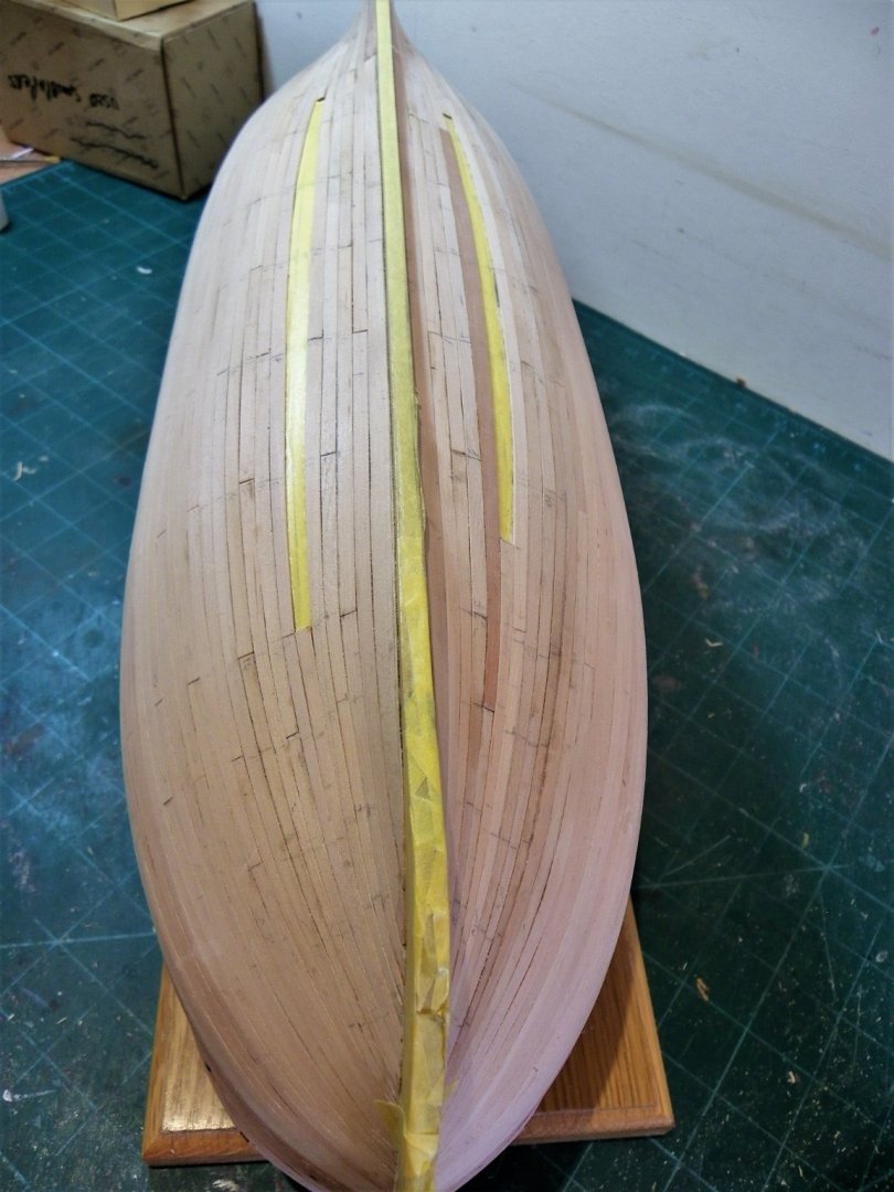
Post Thirty-eight Planking completion With the plank lines re-marked, I begin the final push for completion of the hull planking. I am now alternating strakes both up and down. As each strake is fitted I keep an eye on the likely requirements for the final spiled plank. Something of a forlorn hope that the kit strip wood will meet without a gap. 1248(2) With four strakes to go it is clear that a wider strip will be required for the final plank. The last few strakes take a while to fettle but at 1643 gmt on 20th November planking is completed to my great relief. This last stage of the planking has taken five days the last one is put into place after a full days work on the model. 1267(2) 1266 The final spiled planks, the tape is used as a template. 1268(2) The two darker planks are of wider strip and had to be used as I ran out of the paler stuff of the right dimensions. Fortunately they are positioned well beneath the round of the hull and out of sight in the normal display position. So after three months work the basic hull is completed, time will now be spent sanding the hull to get as good a finish as I can. B.E. 21/11/21
.thumb.JPG.c32495f5235cc108ef7f11327e43083d.JPG)
.thumb.JPG.78d1b02a8101425be42ef8dbb50b8752.JPG)
.thumb.JPG.bae8cdca47d8192d3f58b476b1d6c206.JPG)
- 857 replies
-
- 23
-
-
- Sphinx
- Vanguard Models
- (and 1 more)
-
It looks good to my eye Derek, and I do love that Boxwood finish. I would leave it unpainted. B.E.
- 345 replies
-
- 4
-
-
- Duchess Of Kingston
- Vanguard Models
- (and 1 more)
-
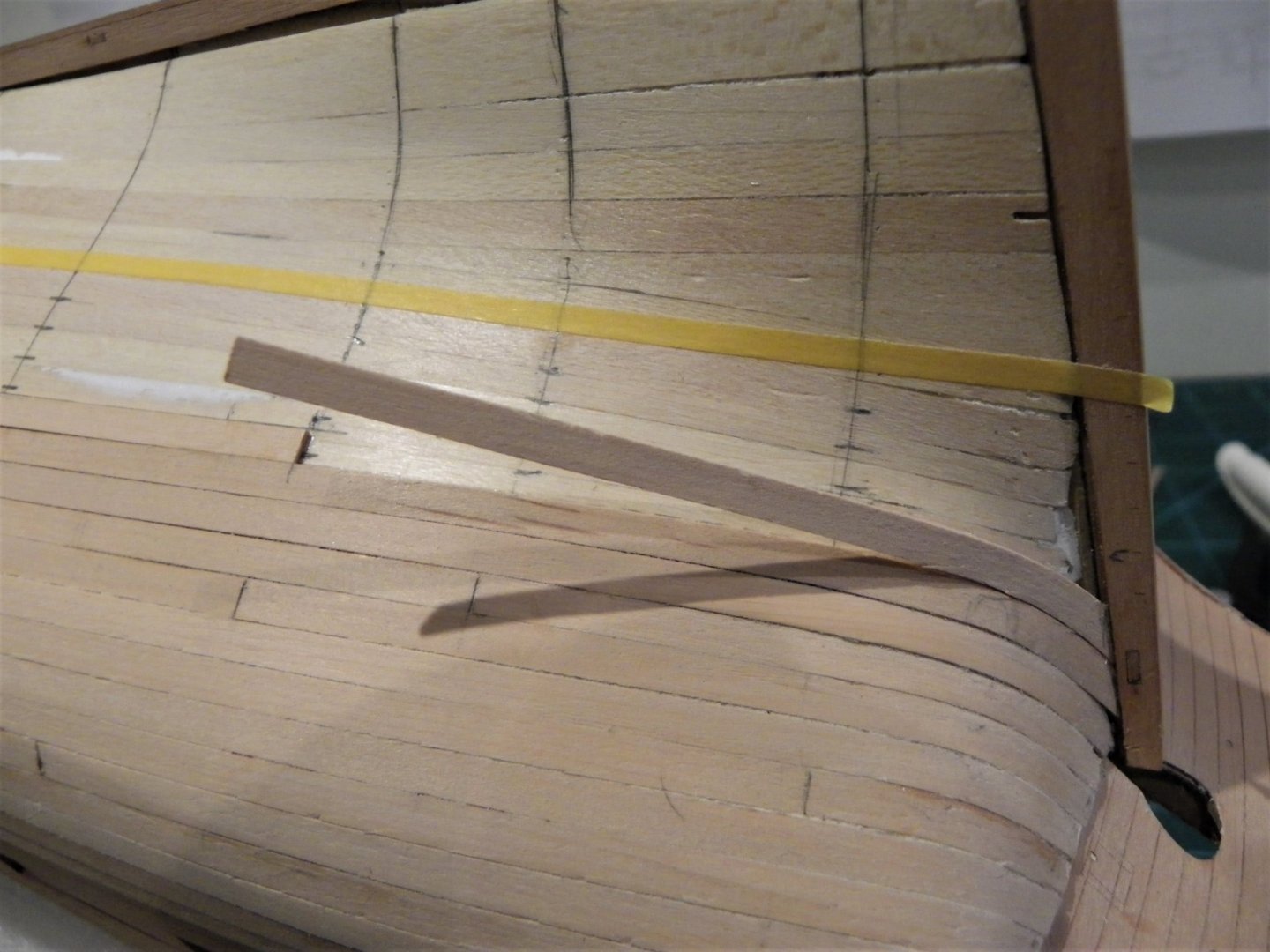
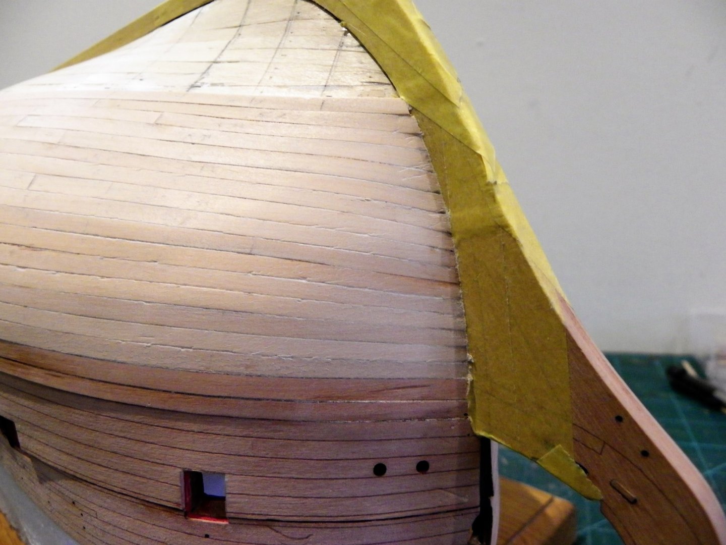
Post Thirty-seven Planking - Band Two In the light of the modifications to Band one, Band two is re-set and the tick divisions re-marked. 1221 In practice I am following the previous planking line and the bow taper remains constant at 3mm. A shallow edge bend at the bow is required on each strake, and full width planks run to the stern. 1218 The run up to the stern post requires both edge bend and twist on the aftermost planks of strakes 11,12,13. 1207 I found it easier with these to fit the stern post edge first and trim the other end to fit the plank butt. The tight curve was formed from a longer strip to ease the process and avoid splitting. With the eight strakes of the second band completed it is time to review and re-check the planking runs. 1236(2) The planking line matches each side as measured down from the keel against the bulkhead positions, and at the bow and sternpost. I had a change of mind about using the extra Pearwood strip I purchased for the wider strakes, the colour difference is too marked against the very pale and uniform kit planking. The resulting spiled planks would stand out too much and be a distraction if I am able to leave the hull unpainted. 1211(2) Any wider spiled planks including the Garboard will be cut from some of the ‘waste’ 0.8/1mm Pearwood fret which is too good to waste. Fitting the Garboard. My best guest is to use a slightly wider 5mm strip, broadening to 6mm at the sternpost. This was cut and shaped from fret Pearwood of a matching tone. At the bow it begins at b/h 1.1 and runs uniformly to b/h9 where it gradually broadens to 6mm at the sternpost. 1213 Once the curve at the stem has been formed the strake is wetted and clamped in position to form the subtle angles as it runs along the keel line. 1224 For the Garboard I used pva glue given the good clamping positions. 1244 1233(2) 1239(2) There are now nine strakes left to do. I will re-mark the plank lines, hopefully to best effect, and work both up from the garboard and down from the wale. The final spiled plank should appear at strake five up from the Garboard, tucked away beneath the hull. B.E. 16/11/21
.thumb.JPG.a763229488764ecc105c97eeedc8e56f.JPG)


.thumb.JPG.0f31952ce8d5f97de97bf5775e1339e2.JPG)
.thumb.JPG.f0b25572cfd104d6c88bc189b1c55826.JPG)
.thumb.JPG.5f58b0b1ec0afc00283f22022c1c8748.JPG)

- 857 replies
-
- 25
-
-
- Sphinx
- Vanguard Models
- (and 1 more)
-
One of the trickiest parts of a build, well done Richard. B.E.
-
Your experience resonates with me bug, but even if you can’t quite maintain the accuracy strake by strake as the second layer is applied, those linings and tIck marks do provide a guide to follow. I find that even after one or two strakes the planks start to run out of sync with the tick marks along the hull. Even with what should be the simplest line marking at the central bulkhead with full width planks the match is invariably off after a few planks are applied. A combination of width variation in the kit planks, and inaccuracies in marking the ticks all contribute to the situation. I work on the basis of running the planks as best as I can down to the required number for the banding, and then re-assess what is required for the remainder. Once I complete the second banding I will remark the strakes and work up from the Garboard. Hopefully the final spiled plank won’t be too weird in shape and will lie below the round of the hull, as does yours. I think you have achieved a good result, and those stealers and spiled planks will be covered by the copper. B.E.
- 419 replies
-
- 6
-
-
- Victory Models
- Pegasus
- (and 2 more)
-
A case for Sphinx I don’t usually invest in a case for my models this early in a build but earlier this year when my regular case maker delivered the cover for the Royal Barge, he announced his retirement. He wasn’t making any more but he did have one ready made that would suit Sphinx as I intended to build her. Today he delivered that case as he was also doing a final delivery to the IPMS Scale model show at Telford. 1196(2) The model sits well in the case, leaving adequate room for a stub Bowsprit. 1198(2) The base already had a ‘tarmac’ finish, a reference to its previous purpose. I was prepared to remove or cover this but I quite like the look. 1205(2) Once I reach the detail stage it will be useful to have a cover to keep the dust off. This is the eighth case Paul of Just Bases has made for me, he will be missed in the Model making community. B.E. 13/11/21
.thumb.JPG.82cd55ee0c4876c6c4d186c634ba2dca.JPG)
.thumb.JPG.da1aae0789e096be8e4ea7112222e09d.JPG)
.thumb.JPG.a9b3d4edf7371a68f7e128c492055049.JPG)
- 857 replies
-
- 22
-
-
- Sphinx
- Vanguard Models
- (and 1 more)
-
I followed Greg Herbert's example in Volume 111 of the ffm. This is also a simplified version, lacking a chimney, and is very similar to the style you decided upon. Regards, B.E.
-
An excellent result Glenn, beautifully finished. B.E.
-
Nicely done bug, silver soldering really is a great asset to make those interesting little 'iron' pieces so difficult to find as completed items. Everyone should try it. 👍 B.E.
- 419 replies
-
- 3
-
-
- Victory Models
- Pegasus
- (and 2 more)
-
The dream team, Jim and Chris and two fine additions to the Vanguard collection. Great stuff. B.E.
- 36 replies
-
- 4
-
-
- vanguard models
- Erycina
- (and 2 more)
-
Thank you Bob, Chuck is the man to follow. 👍 Post Thirty-six Planking - at last. Planking of the first band begins with the strakes fitted in two halves at differing points along the hull. The first strake is covered by the wale. 1125 The first strake fitted, you can see how the tapering follows the tick marks on the hull. I did decide to use ca for fixing . Thinking About a Drop plank This would sit immediately below the Wale, but with the post fitting of the wale pattern it would be tricky to acertain the right level with the risk that the wale would eventually part cover the drop plank set-up, and negate the effect. With two planks fitted there was a good match with the wale bottom at the bow, but an awkward narrow strip would be required further back to support the wale bottom. This would also throw out the planking run. I decided that it was a fiddle too far so, like the plank I dropped the idea.🙄 1133 Three strakes fitted, from this point on I will be below the wale lower edge. 1130 At the stern I wet the plank for a short distance where it curves sharply down to the lower counter. Clamps were used to hold the plank closely down until the glue set, altho’ this was fairly instant with the non runny thick ca I am using. 1138 Here you can see I suffered the issue of a ‘sprung’ plank. Not too problematic just needs cutting with a scalpel and re-gluing. Soft or sprung planks should be attended to they will come back to bite you later on. 1141 From the fourth strake down a degree of edge bending was required, and at this point tick marks at the front half were already showing signs of running off. The band tape was repositioned and Fresh tick marks were re-drawn. The strakes have been divided up into individual planks, not a formal arrangements but roughly in sync with scale lengths. So after four days work the first band of eight strakes is completed. 1179 At the fore end the plank run matches the band line. 1151 At the aft end which was unadjusted there is a slight divergence from the band line. I didn’t want a wider plank at the counter, so this is ok, and I will adjust the position when I re do the second band. 1171(2) The run of the planks to the stern counter. 1169 1149 1177(2) 1178 1167(2) Onto Band two and a repeat exercise. B.E. 11/11/21


.thumb.JPG.25e6f34ea5e02a6100c79a6a320e4e49.JPG)
.thumb.JPG.9bc6a9a2926227ae2cc52373efde824c.JPG)
.thumb.JPG.7bd0499c152467bc5b2f2acf71e442f1.JPG)
.thumb.JPG.696e64dd88359b05da4111108c21a15a.JPG)
- 857 replies
-
- 23
-
-
- Sphinx
- Vanguard Models
- (and 1 more)
-
Hi Steve, You're welcome to use any stuff from my logs that you find of interest, I do it all the time with others. Sharing ideas and methods to increase knowledge and build satisfaction is one of the cornerstones of MSW. Enjoy your build. B.E.
-
Nice looking work space bug, glad the surgery went well. B.E.
- 419 replies
-
- 3
-
-
- Victory Models
- Pegasus
- (and 2 more)
.JPG.5089c21500a5c3f055f86a10a0b01a93.JPG)
.JPG.820fa4868d3366fefd0f0ffbc52648c1.JPG)


.JPG.de5073d83b819e11654d8efe5e4e4dd7.JPG)
.JPG.35df9291d830aed5320f6ee799e0e0e6.JPG)
.JPG.d86ca65d4496beaf2b31d21223b655fd.JPG)
.JPG.96f6cb6f3dd3d4023465f78f9e8d30a9.JPG)
.JPG.80462d1372959890955787fa8b5c3c9c.JPG)
.JPG.d27681496f357b5a42d5dad640df9c09.JPG)
.JPG.c2beff689fc4519677243a831fd2de93.JPG)
.JPG.44236d9fe540941d28d26117ab6572c1.JPG)
.JPG.1bbc0ab5b8bfc7bb7e8aa6dc1107e5a3.JPG)
.JPG.0c32ebf32aa9aea1084e6c50da707765.JPG)
.JPG.bfabb272f7819c1df88331367767e00a.JPG)
.JPG.8ce7789891fa6129d0e1909df8690c09.JPG)
.JPG.7ea2f1d9019a03d95680fa4dc131a385.JPG)
.JPG.12dd1f2ded7d65ea432416f5c905958a.JPG)


.JPG.17a92e97140c25fe8ceaf2b9c5c35559.JPG)
.JPG.92698777c9a14e9287a353b51964f0cb.JPG)
.JPG.869c8ad30236da26a176ccb41bbede61.JPG)
.JPG.984145b746518bc19f3b4550ca2d1d13.JPG)
.JPG.800fd7e22889d24f89f8b9e5c65d3f39.JPG)
.JPG.86997f03879500fe8c8f6ffbadff8bce.JPG)
.JPG.90b9abb8368168630e28c25f0859ff5f.JPG)
.JPG.028e7f6ee3f2ec2641a0d8569b5983a9.JPG)
.JPG.6c179f218abcd2629f69627ce8f1480f.JPG)
.JPG.6e6ec06f528d65351c1efdc830a0c40f.JPG)
.JPG.975816808eccceeaabda732ac4bfe44a.JPG)
.JPG.024dff54f071b5328a008c0bd19fd1e6.JPG)
.JPG.34cfa9bf1b76c2e6e8e3bf3fdbe88118.JPG)

.JPG.b123239e49f3206f98c83b6879784ae7.JPG)
.JPG.7d00e2045b17c8c2c1dc90d1ab78283c.JPG)
.JPG.376fe328963cf040976ed10244bcc4f6.JPG)
.JPG.4c901402b6a01d72aa964cdfdfb52b71.JPG)
.JPG.9053cf9946eaad53635ec895abc11486.JPG)
.JPG.e0fb9b89c1ad998c2ae039b52bc09049.JPG)

.JPG.b5dbefa310c563b7b741c919fe4b4eb7.JPG)
.JPG.0994613b6c16d093689e8ece9855f613.JPG)
.JPG.57922c25edaf3fed18b35977777240e8.JPG)


.JPG.f1627ce5ad60248d441ef2829a7c5689.JPG)

.JPG.a50396c08baa8488cf50701f4183cad1.JPG)
.JPG.511f99e087256ce3b3f667cee902183a.JPG)

.JPG.e0e8b75bd9eaa255b8ecf301ed1cd9dc.JPG)