
.JPG.ca33079f5815b861e67b9c2cccd37982.JPG)

Blue Ensign
-
Posts
4,572 -
Joined
-
Last visited
Content Type
Profiles
Forums
Gallery
Events
Everything posted by Blue Ensign
-
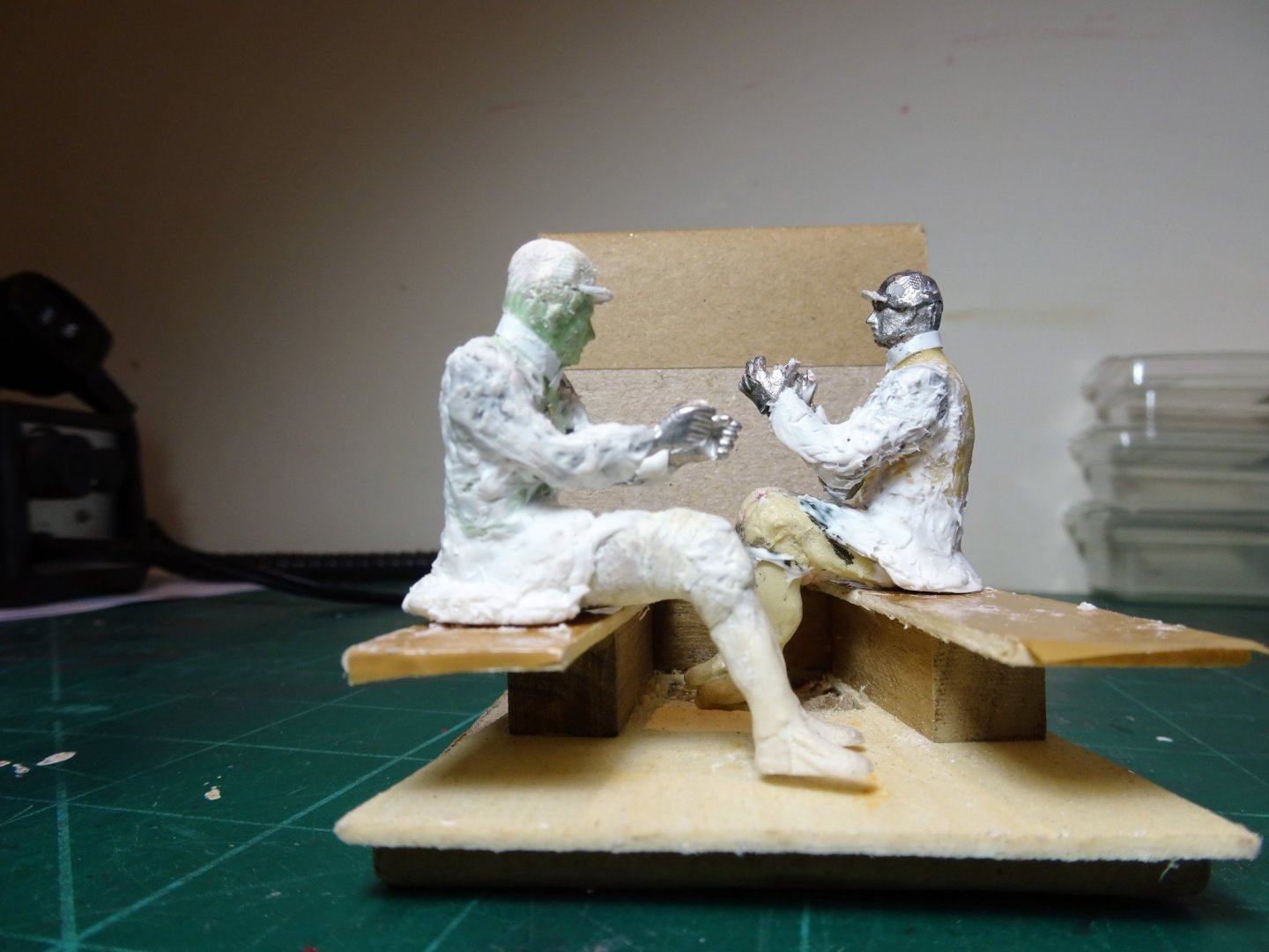
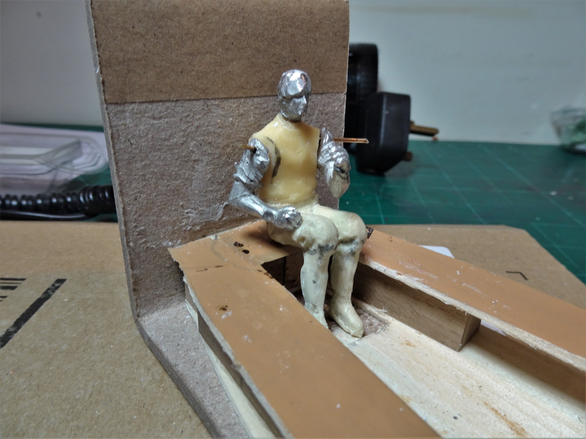
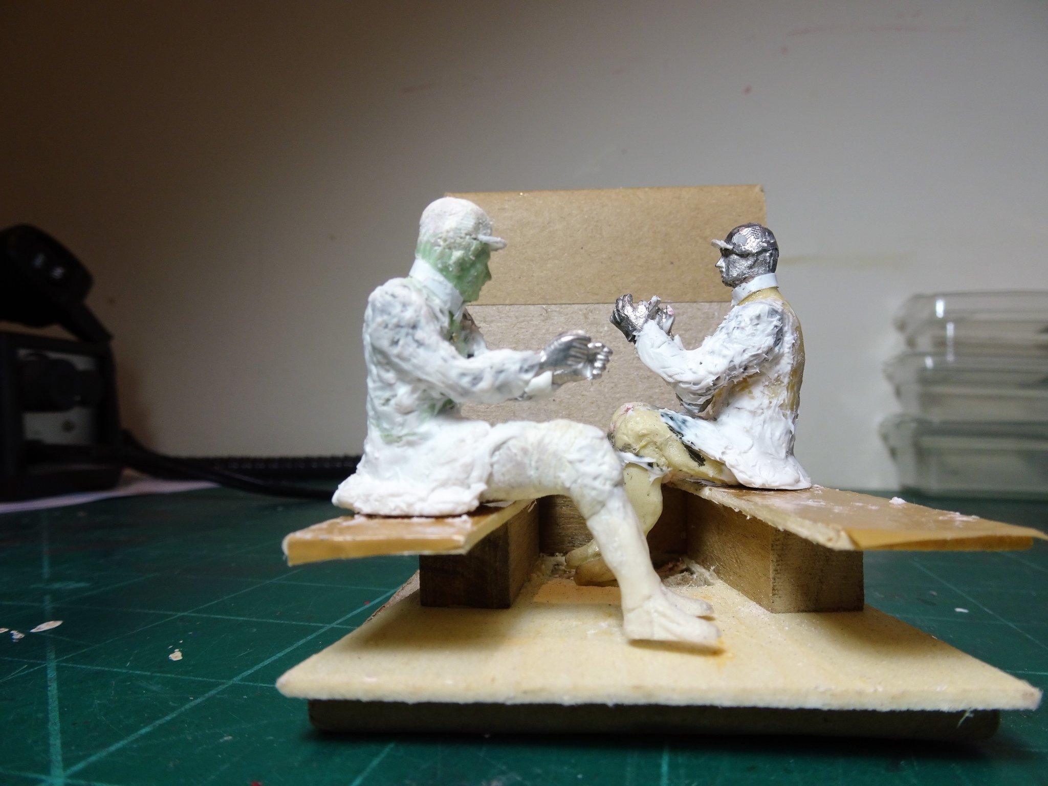
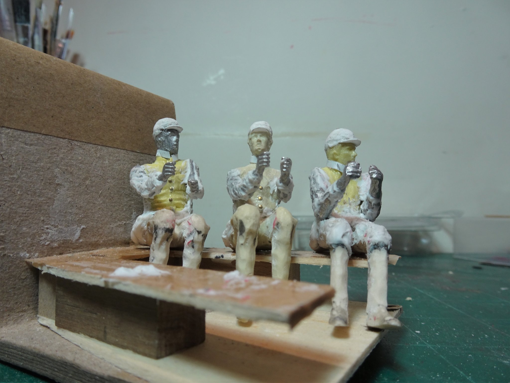
 Thank you Nils, They are an eclectic mix of sitting figures purchased from Deans Marine. Having separate arms and torso helped the 'conversion' to Royal Watermen of the early 18th century. Unwanted detail was removed using the Dremel, and the tunics were added using Artists modelling paste, Milliput, and styrene strip. These stage photos give you the idea. 3257 3388 3283 Regards, B.E.

- 185 replies
-
- 8
-

-
- queen anne barge
- Syren Ship Model Company
- (and 1 more)
-
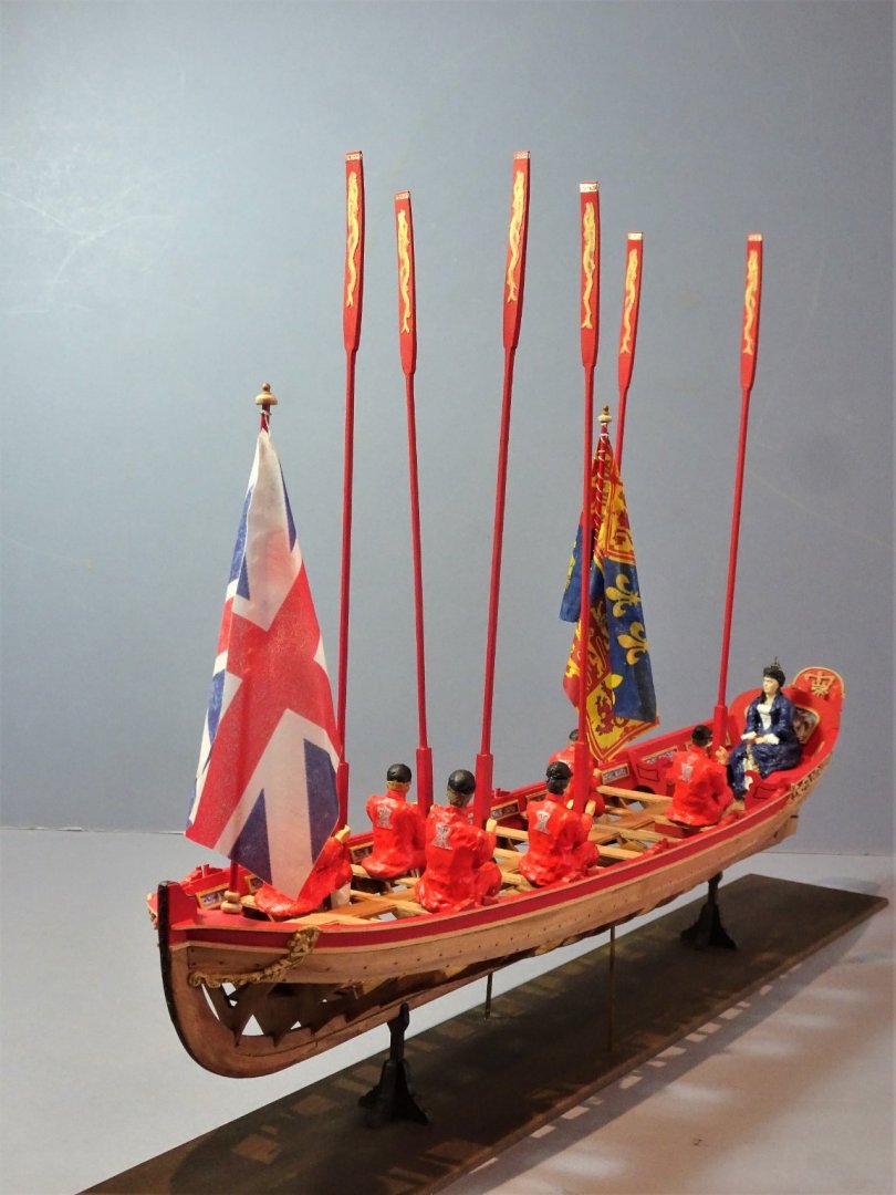
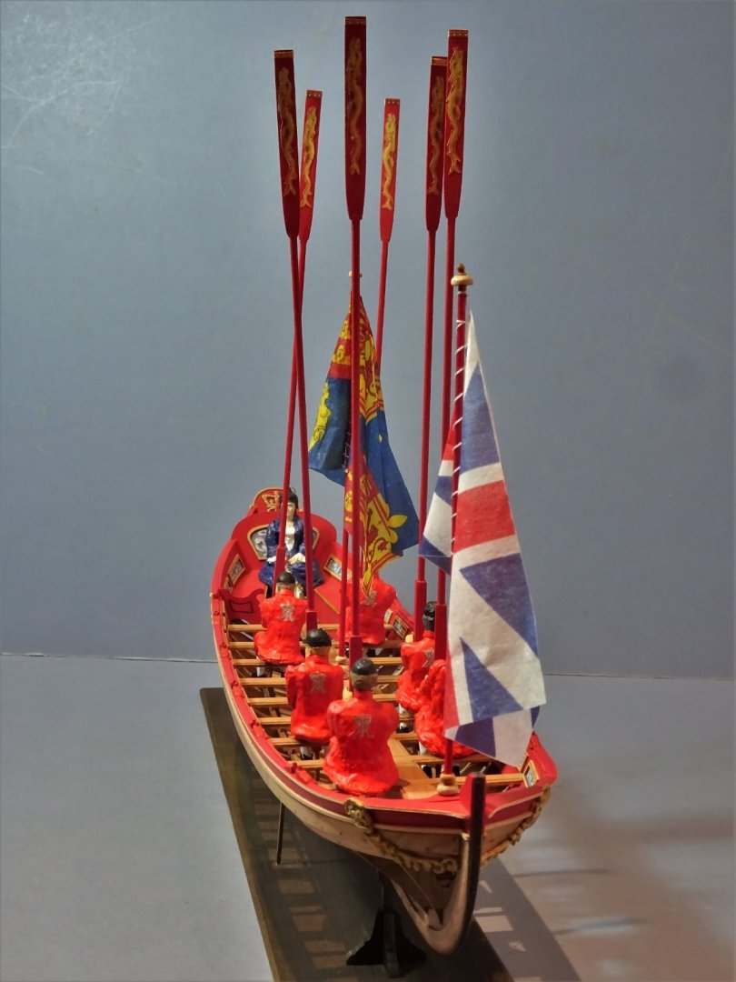
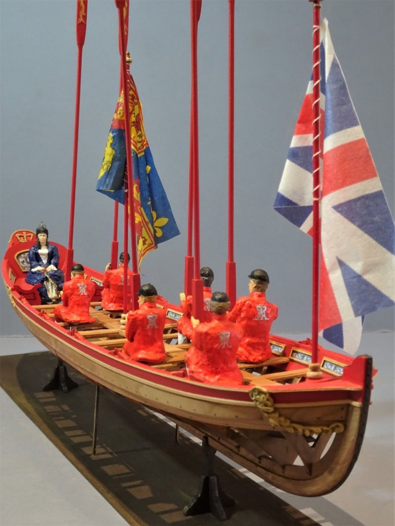
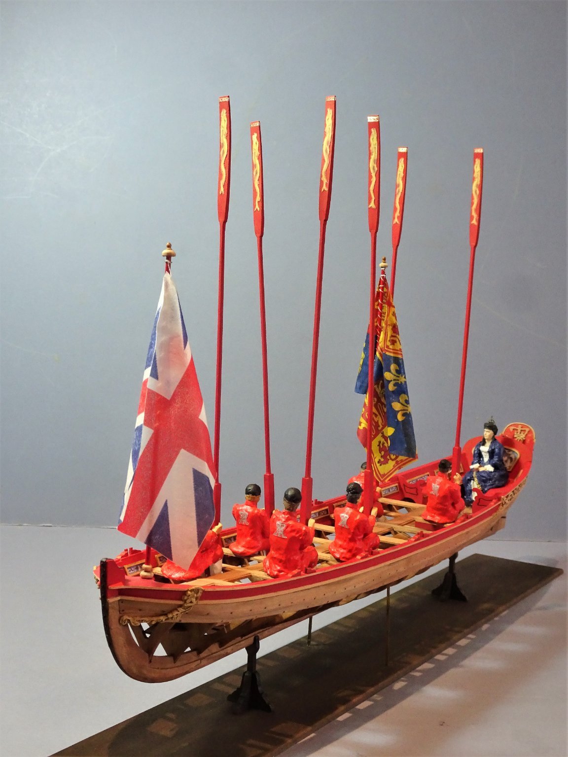
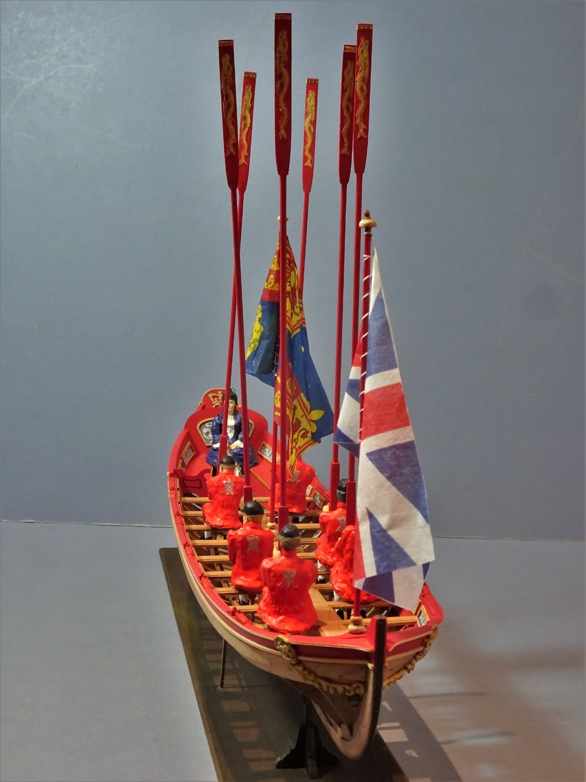
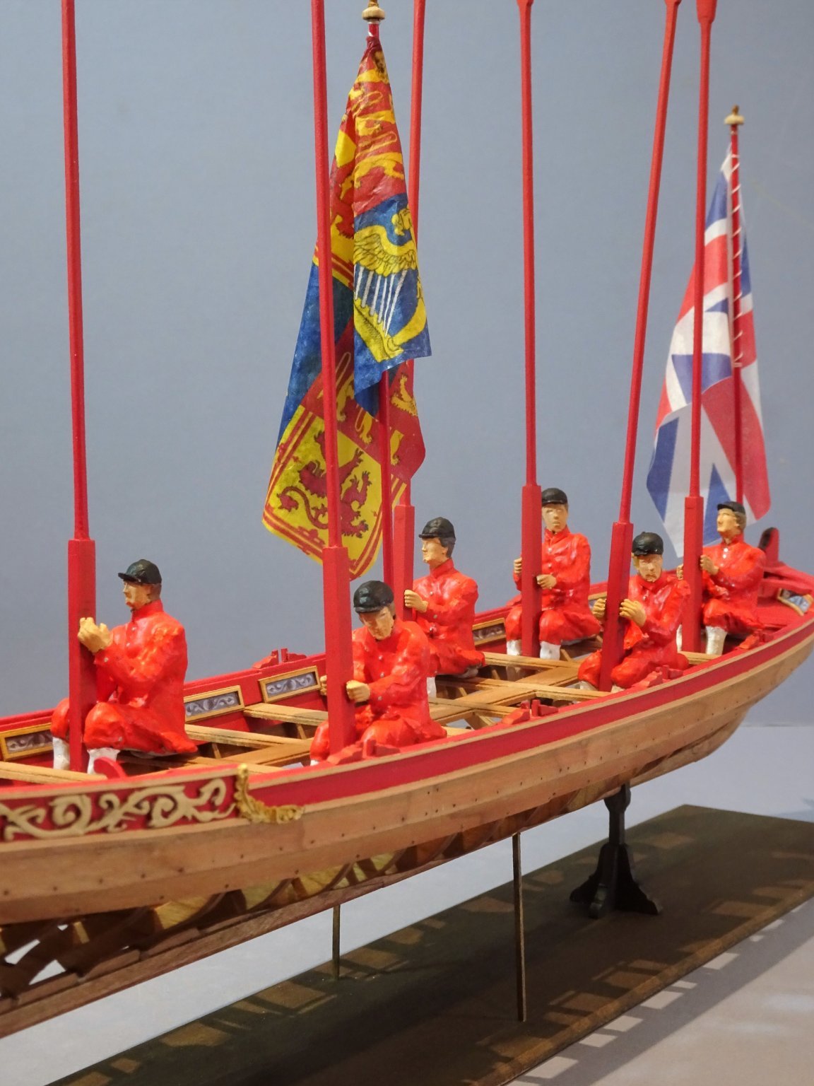
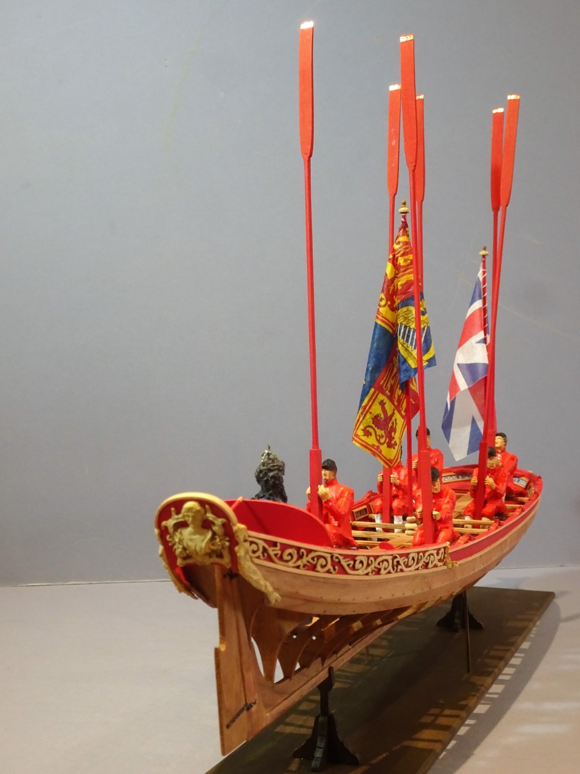
Whilst I await the arrival of my next project I have continued to play around with more Watermen figures to people the barge. After much faffing around I decided on six figures as this seemed to give the best balance on the boat without giving an overcluttered look. The figures as with the original oarsman are all derived from various 1:24 scale figures from Deans Marine. In setting the figures the trickiest part is fixing the oars in the vertical position. I had to resort to smearing ca on the palms of the rowers to secure them. I didn’t wish to mar the varnished thwarts, so a thin strip of Blu-tac was used to secure the oarsmen in place. 3422 3423 3413 3425 3438(2) 3437(2) 3411(3) 3398 3401(3) I think I can now declare the model finally finished, time to clear the workroom for the arrival of Sphinx. B.E. 16/08/2021
.thumb.JPG.7756def7fc387cb891f80731befd41d1.JPG)
.thumb.JPG.3d63f175ec25b7c94dc15b5a8822d9dc.JPG)


.thumb.JPG.42dc04d8f4980014808c7fe52a76a48f.JPG)
.thumb.JPG.eb94e608291a3b14991bcc0d22bff42a.JPG)
- 185 replies
-
- 16
-
-

-
- queen anne barge
- Syren Ship Model Company
- (and 1 more)
-
Feature Suggestion
Blue Ensign replied to CDR_Ret's topic in Using the MSW forum - **NO MODELING CONTENT IN THIS SUB-FORUM**
If you click on the gallery pictures across the top of the page to enlarge it, you won't have the scroll function. You need to click on the build title at the top left of the photo; this brings up all the photo's in the set, enlarge the first one and the scroll arrows will appear. B.E. -
WoW it’s like Pegasus on steroids, 11½ feet longer and 3¼ feet wider at full scale. Come on Chantelle. 😉 B.E.
.thumb.JPG.b08c84e3f78288288da8b43c940f45ae.JPG)
- 857 replies
-
- 12
-
-
- Sphinx
- Vanguard Models
- (and 1 more)
-
Sounds like a bargain to me, not only do you get the Boxwood version, but the boring stuff has already been completed to a good standard. Hope you get a result. B.E.
-
Well done Chantelle, quite a mammoth task I would imagine.👏🏻 I hope you are now fully recovered from your leg break and are firing on all four. I look forward to receiving the fruits of your labours in the very near future. Thank you, B.E.
-
Thanks guys for your support, I do hope I live up to our joint expectations. 🙄 @ WestPort – Thank you, glad my Pegasus build has been of use. @ Greg - I will be using your build of Pegasus as an invaluable reference work for my deck plan layout. @ Neill – matrimonial harmony - Good thinking, assists a build no end. 😄 @ Mark – I’m looking forward to enhancing the exposed deck beams with carlings, ledges, and knees etc; B.E.
- 857 replies
-
- 4
-
-
- Sphinx
- Vanguard Models
- (and 1 more)
-
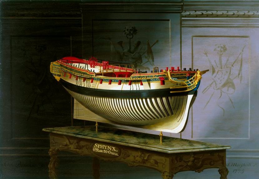
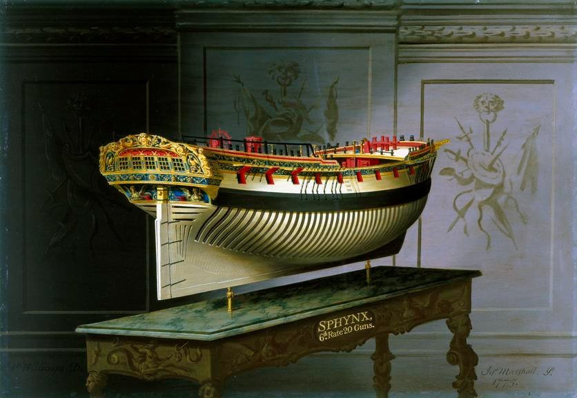
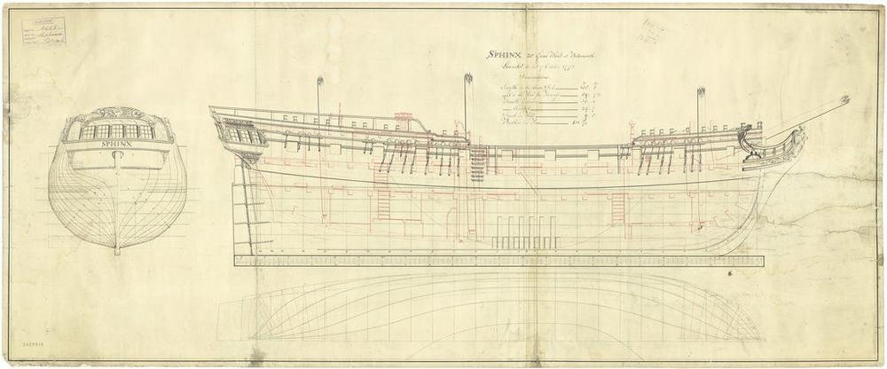
HMS Sphinx 1775 Sixth Rate 20 guns ship - 1:64 Scale model from Vanguard. This will be my latest project, a project the size and type of which, only a short while ago, I thought I would not be doing again. I hadn’t counted on Chris Watton’s ability to beguile me in this late stage of my model building career to return to another 18th century square rigged naval ship. However, as Jim’s prototype build developed, I thought what a fine Navy board style model this would make given the detail included in the kit, and importantly proper deck beams, and full run decks unimpeded by hull carcase bulkhead structures. The inclusion of an engraved proper lower deck with hatches and ladderways down to an orlop deck, is a nice touch and opens further opportunities. I will be building this kit as a Navy board style model without masts or rigging, and that way space considerations will not be a big issue. Joseph Marshall paintings of Sphynx / Sphinx held by the Science Museum. (They are available for purchase as prints.) These two perspective paintings by Joseph Marshall commissioned by George 111 will be my inspiration, as was his painting of the cutter Alert for that build. Altho’ delivery is still a week or so away, I am gathering information, and I have some jottings about possible additions/modifications, but I won’t pre-empt the arrival of the kit. I have also ordered the Lines and Profile plan from the N.M.M. (Ref j4272) Apart from providing additional information, these make very attractive art works to my eye at least, and the framed print will join those of Pegasus and Cheerful on my walls. I have also realised that my copy of The 24-Gun Frigate Pandora (AotS series – by John McKay and Ron Coleman) has much useful information relevant to Sphinx. So, as I continue finger tapping on my desk, in eager anticipation of that large box arriving, I will entertain myself poring over the pdf of the voluminous build manual. B.E. 11/08/2021
- 857 replies
-
- 22
-
-
- Sphinx
- Vanguard Models
- (and 1 more)
-
I replaced the provided (2mm) balls on the Alert kit with 1.5mm diameter ball bearings (natural iron) but it did mean that I had to re-do the shot garlands. 1.5mm balls will be a much better scale fit, with presumably garlands cut to fit, you're leaving me very little to do Chris 😃 B.E.
-
As I recall, the Margin planks didn’t cause much difficulty. I cut them out in one single strip on the jigsaw having used the deck edge to give me the profile. The margin planks can be put down once the inner planking has been completed. If you do it before, extra width will need to be allowed for the thickness of the internal planks. I marked and cut the joggles into the margin using a scalpel point and micro chisels. B.E.
- 562 replies
-
- 2
-
-
- vanguard models
- alert
- (and 2 more)
-
Looks good to my eye, 👍and as the build progresses and deck fittings are added the butt shift becomes less apparent. I used 4.5mm wide Boxwood strips for the deck planking which is what I had to hand at the time. (Post15) I would otherwise have gone with 3.4mm strips equating to planks of 8.5 inch widths. Regards, B.E.
- 562 replies
-
- 2
-
-
- vanguard models
- alert
- (and 2 more)
-
I'm looking forward to it Tim, I will have some reference guides to the style I am intending, Chuck's Winnie build, and Greg Herberts Pegasus build as detailed in Vol 111 of the FFM. B.E.
-
I have written only recently that the era of building large 18th century square rigged warships was over for me, feeling perhaps 75 was too old to start such a project, coupled with where to put it issues. However, despite my best resolve I have once again fallen victim to the siren song of Chris’s latest offering. I spent yesterday evening looking at the eye candy photo’s provided by Chris’s fellow conspirator, James, looking for reasons not to wing £665 across to the Forest of Dean. All to no avail, even Mrs W said stop messing about and press the button. So, Sphinx will be my next project, but there will be compromises; I will build her as a Navy Board Style model without masting and rigging, and with much of the decking left off to reveal the wealth of detail provided by Chris. At least with this model, Chris has thoughtfully designed all the below decks detail so I won’t have to gut the innards as I did with Pegasus. In the meantime, back to figure bashing for the barge. B.E.
-
Thank you Guys, I've now created such books for my last eight builds, it's fairly straightforward to do with the build photo's already on file, they're really an abridged build log from MSW. 🙂 B.E.
- 185 replies
-
- 2
-
-
- queen anne barge
- Syren Ship Model Company
- (and 1 more)
-
That's great news for Chris, providing a much welcome return on his outlay in producing this rather wonderful kit. 👍 B.E.
-
Postscript Today my latest pictorial build record arrived from the printers covering my Royal Barge build. A few sample pages. 3266(3) 3264(3) 3263(3) 3262(3) 3265(2) I find compiling a record such as this a nice way to wind down from a build before the next one is started. Still undecided about a next main project I am going to continue adding Watermen to the model, a chance to improve my figure conversion skills. My idea is to add a maximum of five oarsmen to the boat if things go well. Cheers, B.E. 05/08/2021
.thumb.JPG.53bb0c11f4efb445ef7f329968045516.JPG)
.thumb.JPG.309a79646a9c8b550d59c873e6a22996.JPG)
.thumb.JPG.92daae6801db2e09a65a28685e3f0874.JPG)
.thumb.JPG.ea72097f9234010580404bdd2423c41a.JPG)
.thumb.JPG.d9dba78cc2d1e5d386fd45f59ed74f31.JPG)
- 185 replies
-
- 12
-
-
-
- queen anne barge
- Syren Ship Model Company
- (and 1 more)
-
She does have a nice look about her Tim, and incidentally I quite like the look of a model completed with just lower masts and rigging in place, convenient where space is an issue. Congratulations on your forthcoming all important 'project'. 🥂 Later this month it will be 50 years and many models completed in my case, I do hope your wife to be is sympatico with your modelling interests, as mine has been over all these years. 🙂 B.E.
- 164 replies
-
- 4
-
-

-
- fly
- Victory Models
- (and 4 more)
-
Cutters make fine looking models, and I think you will enjoy the experience of building this kit. Chris has done a great job in simplifying those areas that may present difficulties for those new to kit building, but the main challenge remains the hull planking; take your time with that and make as good a job as you can with the first layer planking as a rehearsal for the top layer. Regards, B.E.
- 562 replies
-
- 4
-
-
- vanguard models
- alert
- (and 2 more)
-
I’ve grown to like Chris’s clear stands, used them on all three of my Vanguard models. They are stylish and don’t detract from the model. I’ve never favoured the pedestals thro’ the keel approach, preferring keel blocks, but that’s just my preference. B.E.
-
Thank you John for your generous words, glad you liked the Pegasus log, she was a long time in the making, seven years on the stocks, but she remains one of my favourites. 🙂 B.E.
-
I like the way she's coming together Jean-Paul, very smart, and those wales look excellent. Your below deck cabins will look great with subtle lighting showing thro' the skylight, I look forward to seeing that in the future. B.E.
-
Thank you, Hubac, Jason, and Mike, much appreciated. 👍 B.E.
-
Thank you Guys for your generous comments, and a special thanks to Chuck for making all this possible. As for what's next, I have completed six models over the past two years of various scales and types, so I'll wait awhile before I decide. In the meantime I do have Chuck's little Double Capstan kit on the shelf, and I've thought that it may make a nice little addition to the case of my Pegasus model. 🙂 Regards, B.E.
- 185 replies
-
- 4
-
-
- queen anne barge
- Syren Ship Model Company
- (and 1 more)
.JPG.2d0090895e9ace0b096162729191c475.JPG)
.JPG.7f62f346239614089f41a50cff3d048c.JPG)

.JPG.0d7a295a88b0b705aec6b9e53888a635.JPG)
.JPG.5762905471f6d5e845fced60e00993c0.JPG)
.JPG.45589c91c0fcfb4faf4d38b1bb380769.JPG)
.JPG.5429fc839684b1a7d721a54b824d0422.JPG)
.JPG.58a6027e17e239ce68c8c536b8bd449b.JPG)
.JPG.f116fc34f13d9a38f33a385f87955d13.JPG)
.JPG.86e1bb99852329f0519d217d75090a7f.JPG)
.JPG.4587327ad80c757893bf524f67f306da.JPG)