
.JPG.ca33079f5815b861e67b9c2cccd37982.JPG)

Blue Ensign
-
Posts
4,572 -
Joined
-
Last visited
Content Type
Profiles
Forums
Gallery
Events
Everything posted by Blue Ensign
-
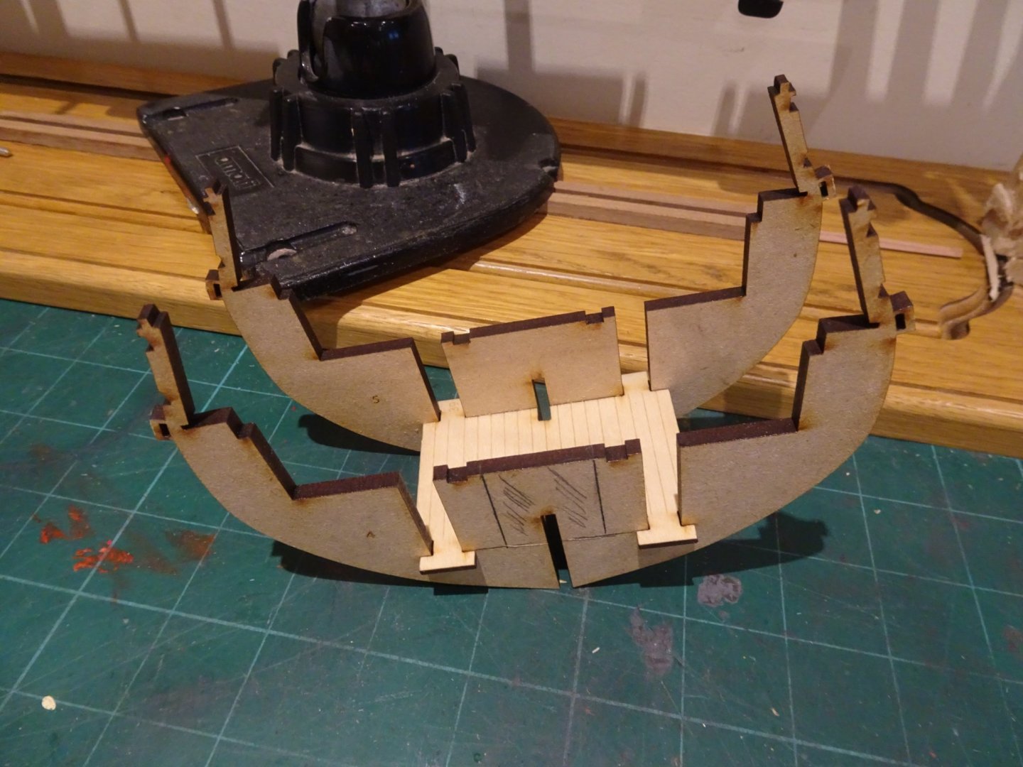
 Post Three Platforms Unusual in this type of kit, Chris has provided a short section of what would be the forward Platform below the lower deck. In reality there would also be an aft platform which is not supplied. These Platforms sat above the hold and are version of the Orlop deck on larger vessels. I doubt very little will be seen of this with the hull planked and decked. I considered the possibility of fabricating false frames and leaving an opening in the hull at this level, but what would be the ladderway above it is blocked by a bulkhead, and it is only clear above the Fore Hatchway. As a ladderway leading up to the Lower deck would be the only feature of interest I decided to pass. Lower deck This deck is another nice touch for what otherwise would be a re-inforcing piece to square up the bulkheads and provide some rigidity to the hull. This is also supplied in engraved plywood with the Hatchways and Ladderways detailed. The Fore Ladderway leads down to the Platform deck, or it would if the bulkhead wasn’t in the way. My deck had some Laser burn on the engraved side which needed sanding to remove. This didn’t have any effect on the planking lines. 3681(2)text With the Lower deck slotted into place, gently does it on this exercise, it can be seen that altho’ the hatches will be covered by gratings, the Ladderways simply open onto bulkhead tops. 3680(2) The Upper deck base is placed roughly in position to gauge what will be visible of the lower decks. The Upper deck Fore Hatch is covered by a grating, but without it there is a view directly down to the Platform deck, altho’ the deficiency in the ladderway will be visible. 3684 To rectify this would require removing a section from bulkhead 4 and a section of false keel between bulkheads 9 and 10 for the lower deck aft ladderway. None of this of course is necessary but as my version will be open decks only, it is another option to think about, and I am sorely tempted. B.E. 26/08/21
.thumb.JPG.7729b0bb954e45bab2f3d8e8cf36f06d.JPG)
text.thumb.jpg.a205c0caeb43386660bf52d3d56898f2.jpg)
- 857 replies
-
- 12
-

-
- Sphinx
- Vanguard Models
- (and 1 more)
-
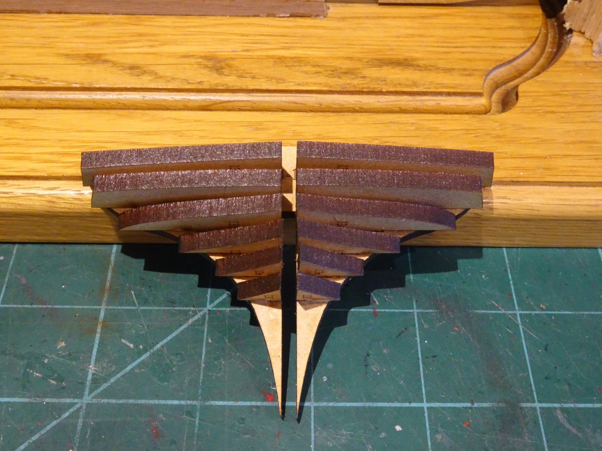
Thanks James, it looked quite a lot in the photos, I was concerned about taking too much off and getting out of shape. On the model you can constantly check progress with a planking strip. B.E.
- 857 replies
-
- 5
-
-
- Sphinx
- Vanguard Models
- (and 1 more)
-
Thanks Jeff, I haven't got that far yet, but I do intend to check the plans for a suitable profile.👍 B.E.
- 857 replies
-
- 2
-
-
- Sphinx
- Vanguard Models
- (and 1 more)
-
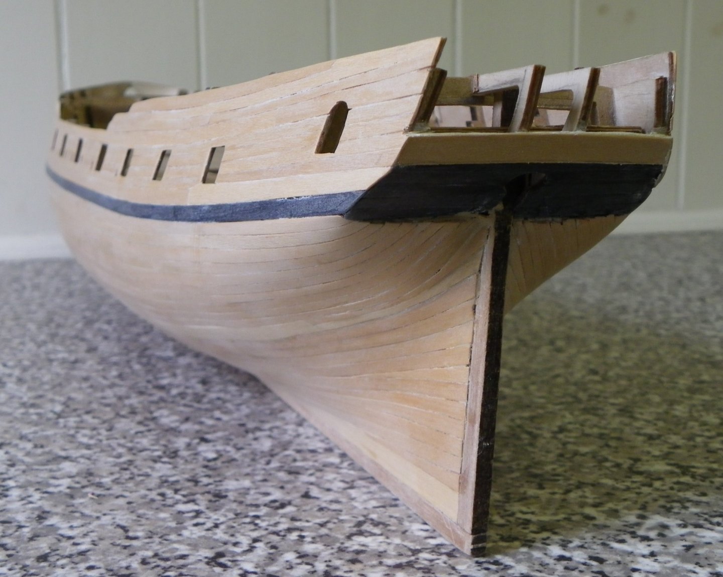
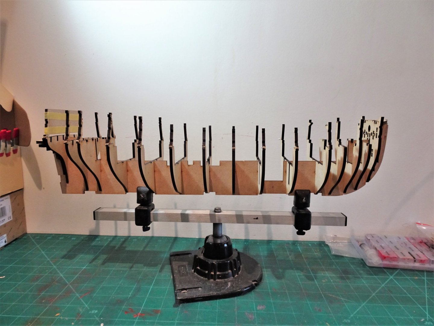
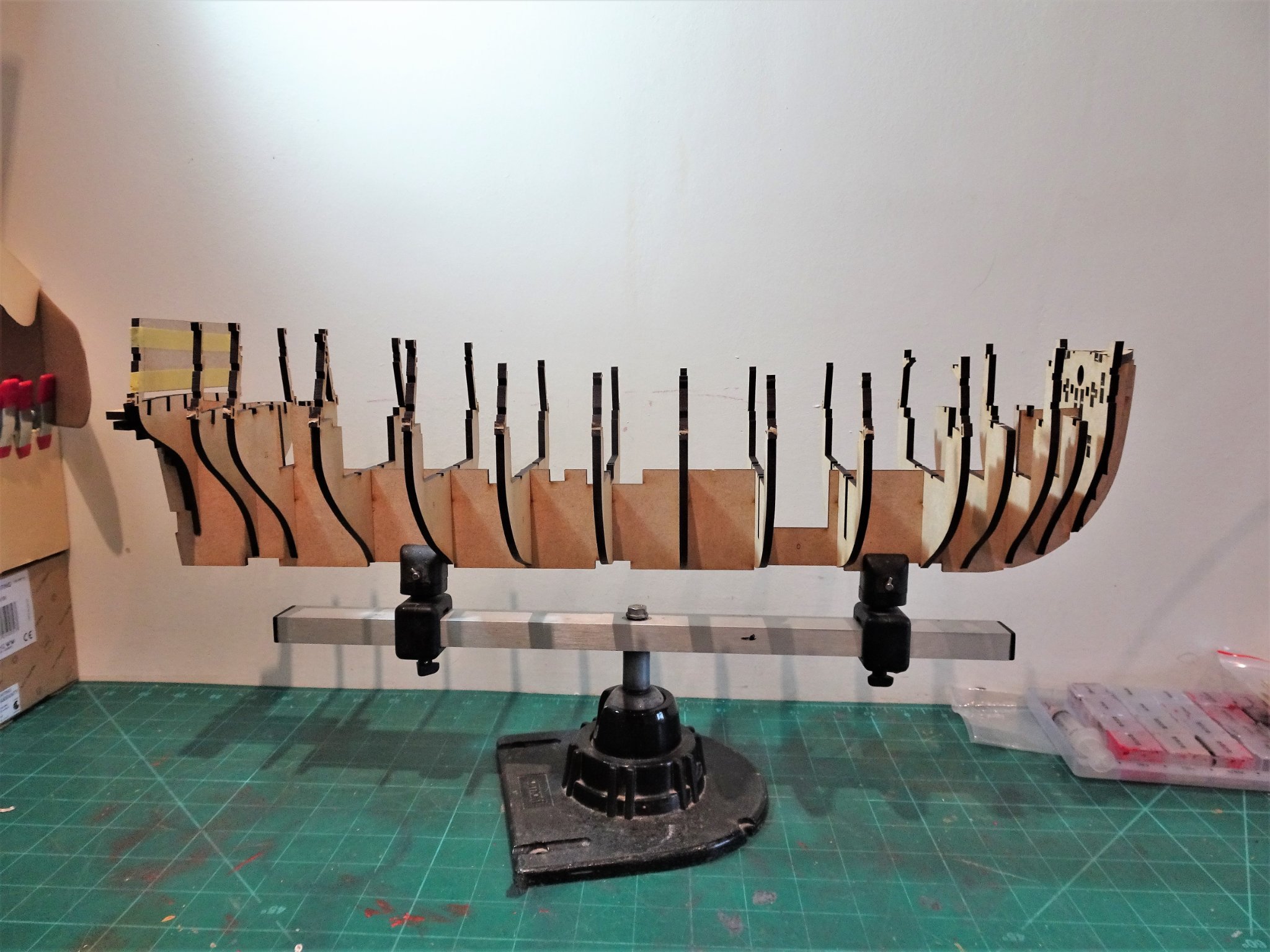
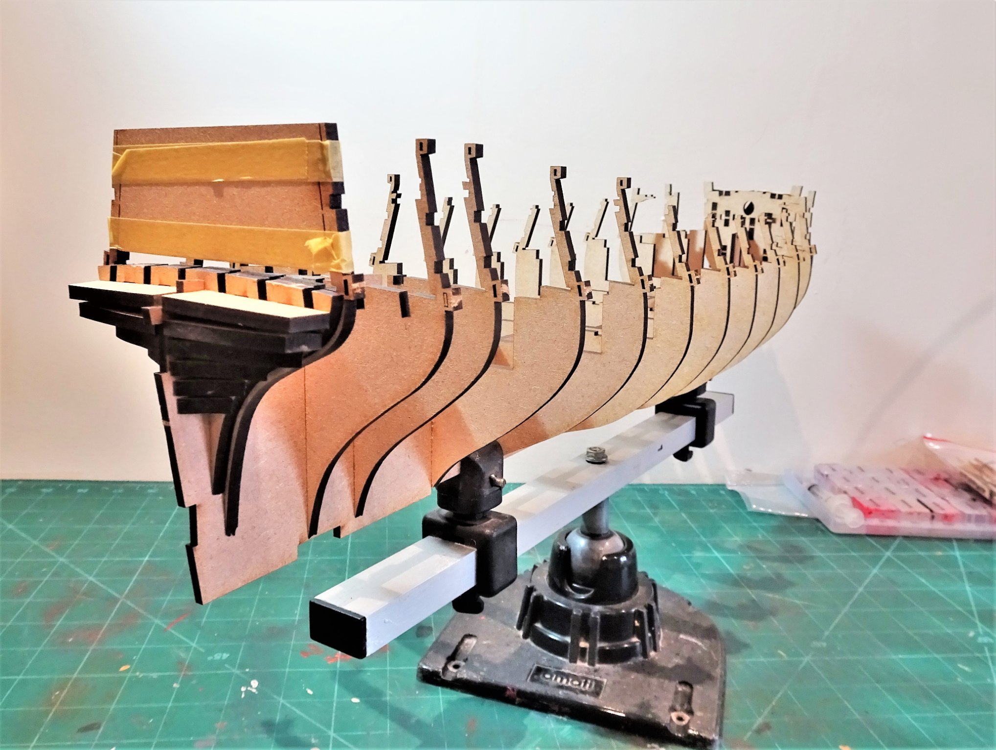
Post Two Bulkheads Fitting the bulkheads is a painless exercise, the one that gave me some concern is the lower stern pattern. (13-1) 3626 Fairing off the model is indicated but in this area it is all about degrees and I worry about how much to do off the model. This is where the lower planking will sweep up to the transom and it needs to be a smooth convex curve without any hint of an angle. 032 This photo of my Pegasus build shows the run of planking and ultimately the fairing can only be done on the model using test planks. For this reason, I will be very careful how much off model sanding I do in this area, and I don’t think I can trust myself with the Dremel. I found that part 13 needed a little light sanding in the slot and several dry fits before it would slide smoothly down the keel to be glued to 13-1. 3679 These things are fragile and cannot be forced into position without the risk of damage. 3677(2) The bow patterns are easier to fit, and will be easier to fair. 3678 With all the bulkheads in place I get my first real impression of the hull size and shape. She is chunkier than Pegasus and is pleasing to my eye. The Bow and Stern bulkheads will now be removed for preliminary fairing, at this point the remainder of the bulkheads are only dry fitted but will probably not require removal again. B.E. 25/08/21

.thumb.JPG.6f2d47f31e1982eccb8adebc9fd707b3.JPG)

- 857 replies
-
- 23
-
-
- Sphinx
- Vanguard Models
- (and 1 more)
-
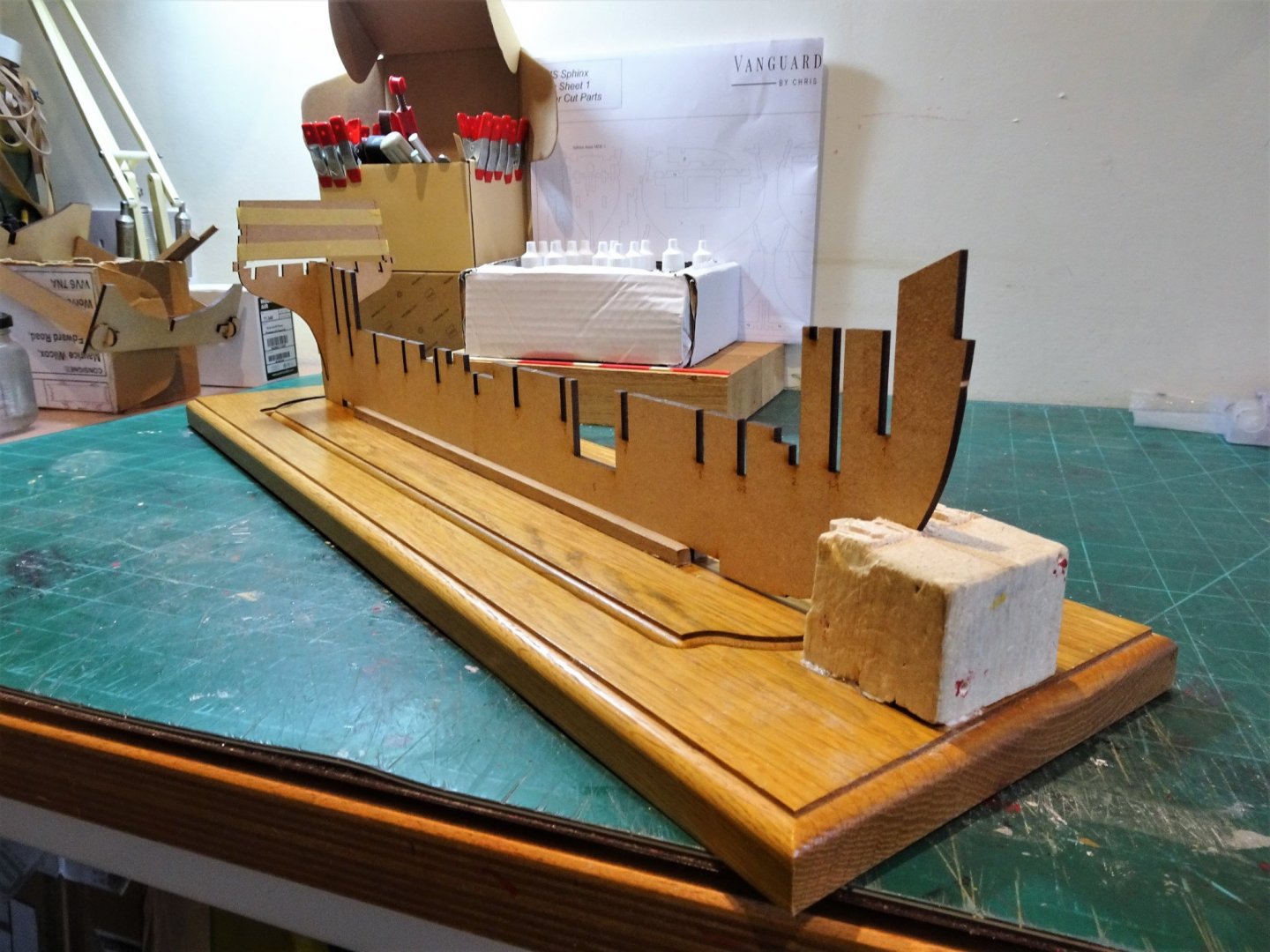
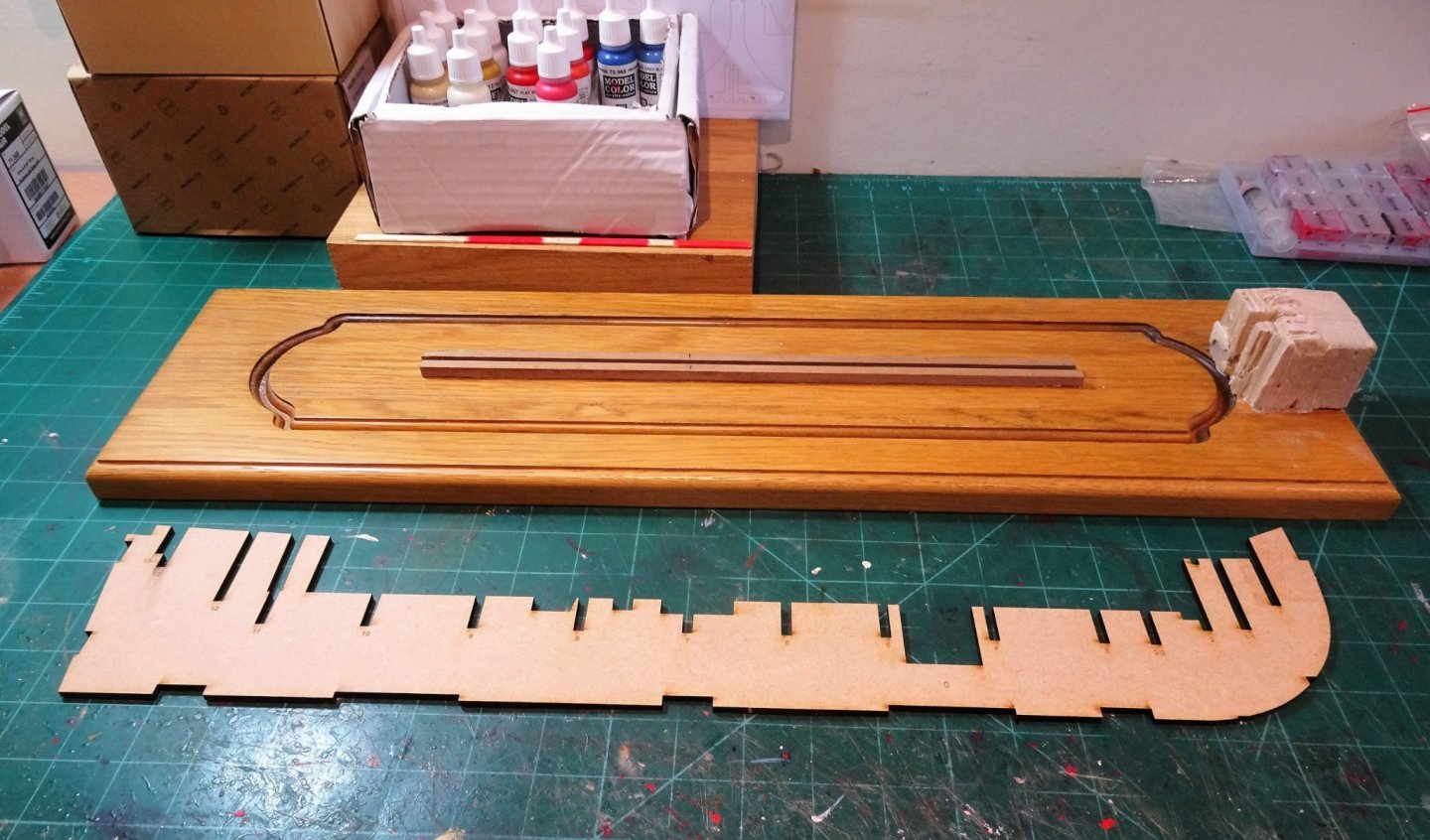
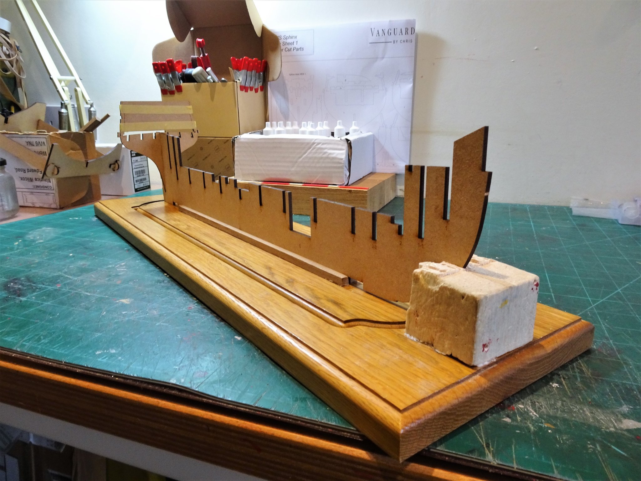
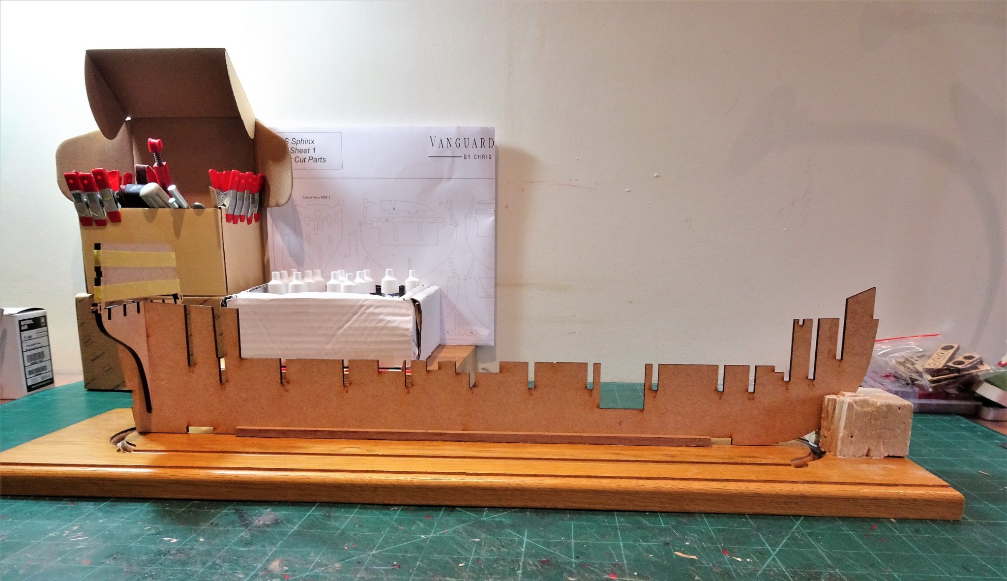
Building the Sphinx - Post One This is where the build starts in earnest, I always start a build with a keel support, partly to hold the hull in the early stages and partly to keep the false keel straight. It also provides a level surface to check square. 3625 3624 3623 This will be modified several times during the course of the build. I don’t intend to do a step-by-step assembly log, there is the excellent manual for that. I do have to mention what a wonderful job Chris and James have done in producing the manual, probably the best I’ve ever seen. My initial view of what I have seen in the box is very positive, I have not concerned myself with checking every part against the parts list as I know Chris will respond to any issues that may crop up. I will restrict this log to commenting on areas where I have had difficulty or found problems (hopefully very few), areas where I have made modifications, and the approach I have taken in tackling different stages of the build where it diverts from the indicated path. Time to introduce bulkheads to false keel. B.E. 24/08/21

- 857 replies
-
- 24
-
-
- Sphinx
- Vanguard Models
- (and 1 more)
-
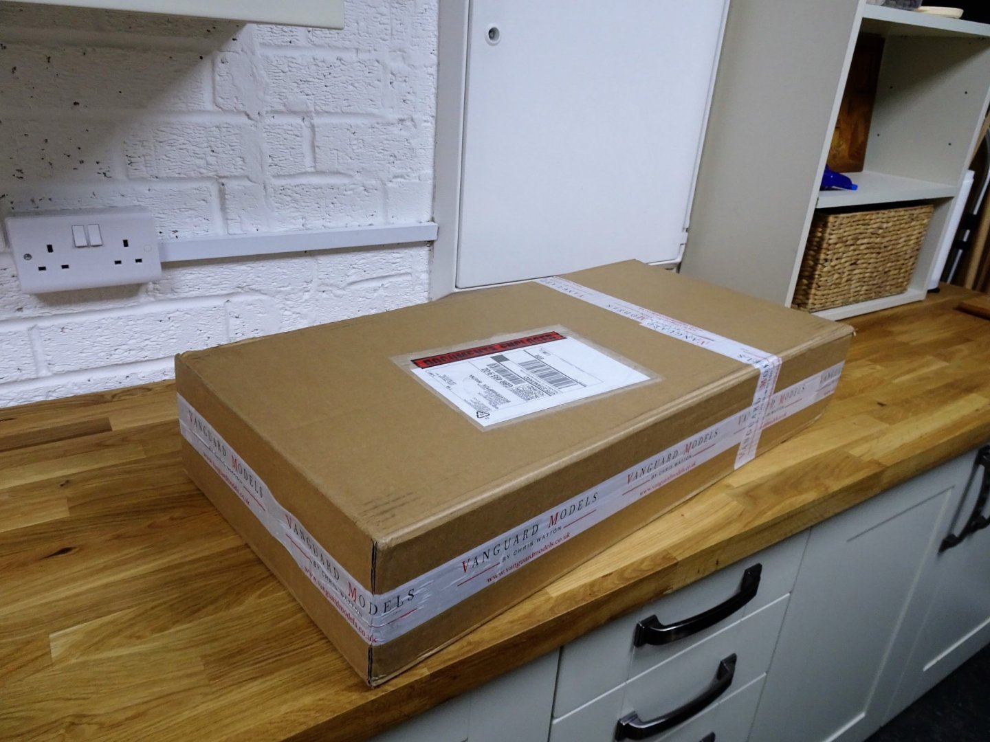
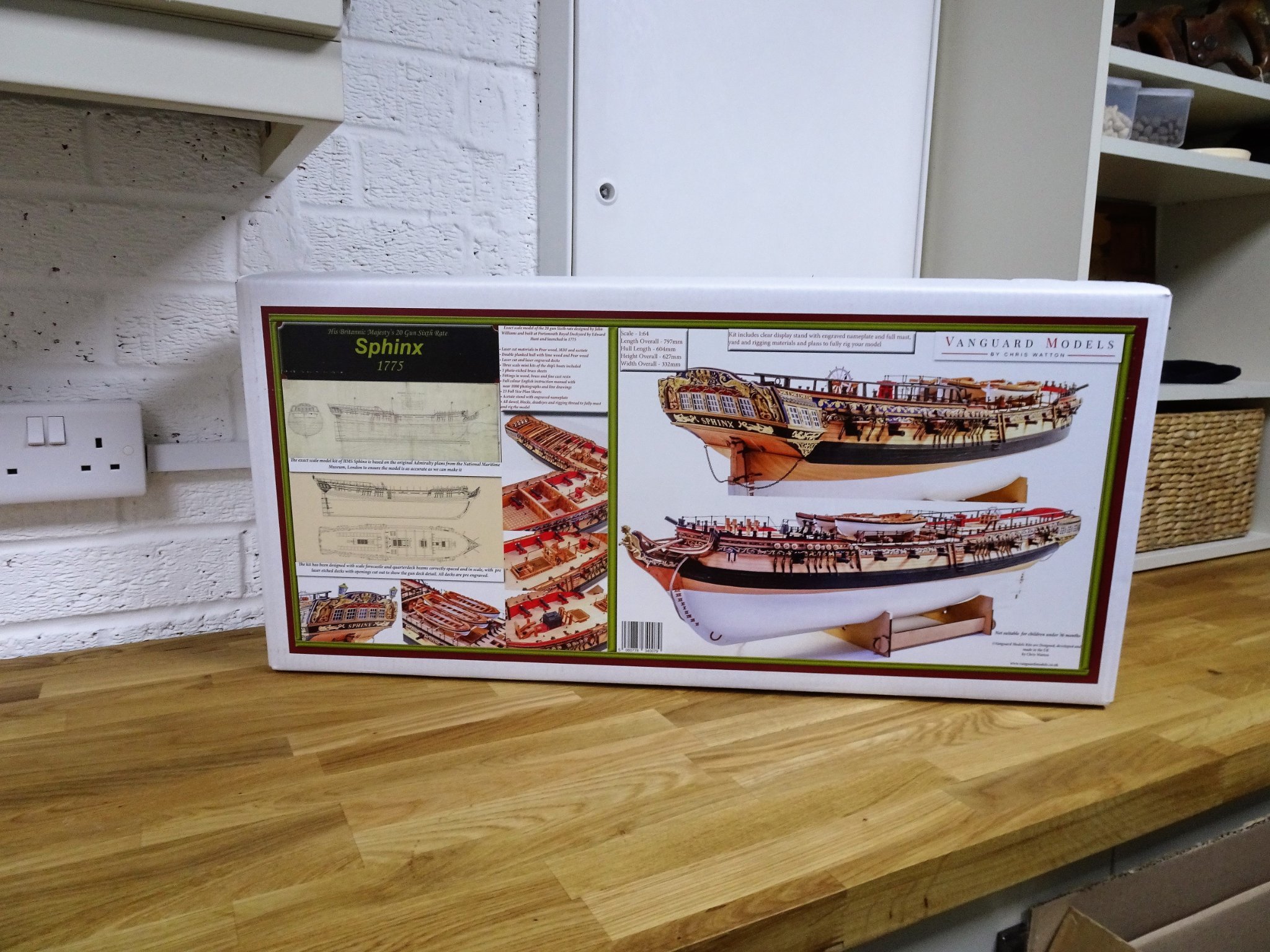
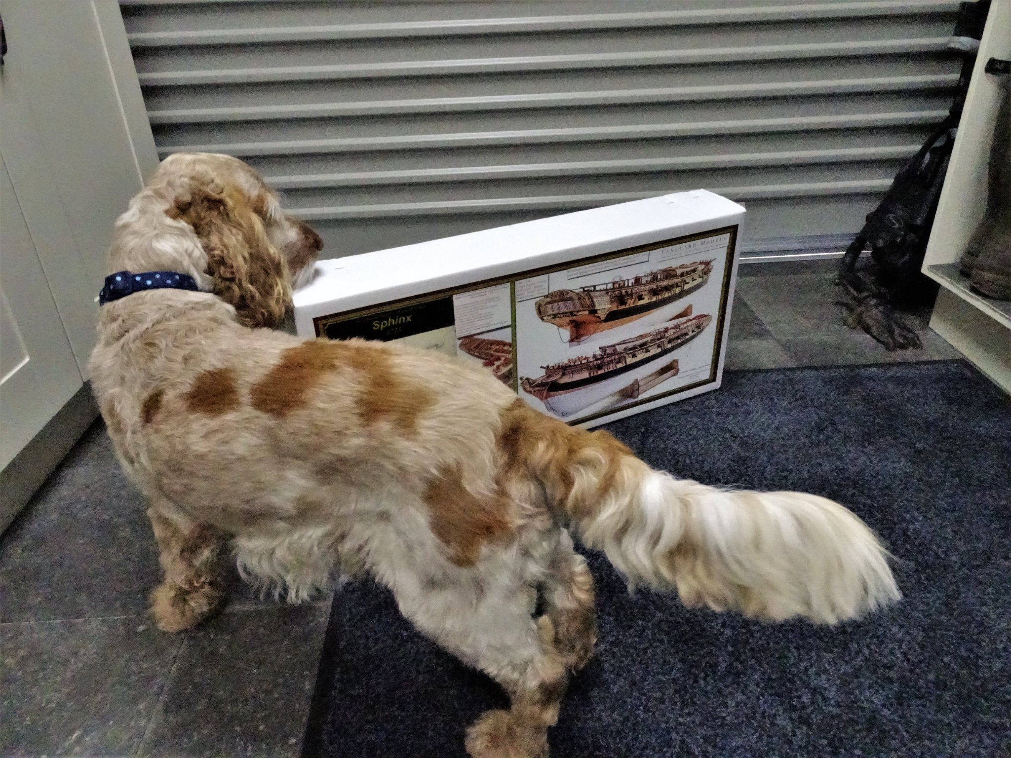
10.25hrs this morning and the much anticipated box arrived. Well protected. A feast for the eyes. Looks like there will be no furlough for you Wills, long days in the shipyard ahead. You can relax for a while tho' the stuff needs to be sorted into separate boxes for ease of working. B.E. 24/08/21


- 857 replies
-
- 21
-
-

-
- Sphinx
- Vanguard Models
- (and 1 more)
-
The Fully Framed Model, HMN Swan Class Sloops, 1767-1780, by David Antscherl and Greg Herbert, published by Seawatch Books in four volumes. B.E.
- 857 replies
-
- 3
-
-
- Sphinx
- Vanguard Models
- (and 1 more)
-
Thanks for the heads up Chris, I am a compulsive book buyer; that one looks interesting but will have to wait awhile. I think I'm pretty settled on the shade I want for this particular model, but in practice it's all artistic license, the official colour for topsides on British ships was any colour as long as it's black. The Admiralty order dates back to 12th July 1715, and is cited by L.G.Carr-Laughton in his book Old ship Figure-heads and sterns. This would apply more certainly in relation to a modest ship like Sphinx, but my model will display her with a fetching shade of blue as ground to the friezes , which in practice she probably didn't have either. B.E.
- 857 replies
-
- 3
-
-
- Sphinx
- Vanguard Models
- (and 1 more)
-
Great planking job you’re doing there Jason. 👍 B.E.
-
That's an excellent video Richard, and of great value to the modeller. It informs both scale and use of the many fittings, as well as being of general interest. B.E.
-
The copy I have is the third impression published in 1981, it only has 'Sailing Trawlers' on the spine, but the inside Title page includes the sub title The story of Deep-sea fishing with long line and trawl. My copy was published in Great Britain for David &Charles (Publishers) Ltd, and is published in the USA by David & Charles Inc. It is a 384 page book, and I don't think you need worry whether it is some sort of abridged version, it contains all the plans and rigging tables. It is in exactly the same layout as the companion volume Sailing drifters of which I have the original 1952 version. This volume is of great interest to those building the Fifie and Zulu models, and I used it extensively in my builds. B.E.
-
You know the old story Chris, the Germans made the rules, the British obeyed the rules, French ignored the rules, and the Italians said rules, what rules. B.E.
-
Erik, if you can get hold of Sailing Trawlers by Edgar J. March there are details of her scantlings and rigging sizes, together with four pages of plans. B.E.
-
I wish, and who could resist a day out in The Forest of Dean, our spaniel would love it. 😃
-
Relief short lived then,🙄 My two bottles bought some time ago have the control numbers K-03-06 on the label. B.E.
- 857 replies
-
- 2
-
-
- Sphinx
- Vanguard Models
- (and 1 more)
-
Don't bother wrapping it Chris, I'll drive over and pick it up😉 B.E.
-
I didn't realise that James may have been referring to a different 'Red' I picked up the use of 'flat red' from members who had used it on their builds. I think I first used it back in 2017 on my Model shipways Pinnace build, and have used it on all builds since, latterly on the Royal Barge kit. It always pays to test any paint on a strip of the wood to be used, before applying paint to the model. B.E.
- 857 replies
-
- 4
-
-
- Sphinx
- Vanguard Models
- (and 1 more)
-
Thanks James for the heads up, I'll keep a watch out for that. 👍 I had a similar issue with Admiralty Red Ochre some years ago, one bottle came out with a distinctly unappealing pink effect. Regards, B.E.
- 857 replies
-
- 2
-
-
- Sphinx
- Vanguard Models
- (and 1 more)
-
Thinking About colour There are four main colours other than black to be used on the model. Red, Blue, White, Yellow, and shades thereof. On every build I have done the actual shade has exorcised my mind, particularly for the colour blue. I am interested to see how various tones look against the mainly Pearwood finish. 3538(2) This is my rough colour comparison chart painted on a Pearwood background. All I am interested in here is how the colour relates to what will be the bright finish between Wale and Waist rail. The colour selection features paints from Vallejo, Admiralty (Jotika/Caldercraft) and Humbrol. The majority are water based but the Admiralty Red Ochre and Humbrol RAF Blue are oil versions as I didn’t have the acrylic versions to hand. I favour the more muted tones as seen on contemporary models, and I hope with this build I can settle on a colour that does not require mixing as that relieves me of working out a formula for re-mixes. My initial thoughts are:- Vallejo Flat Red - inboard works and some deck fittings. Vallejo Grey/blue - Ground to the Topsides and stern decorations. (Humbrol RAF Blue (96) runs a close second.) Admiralty Yellow Ochre – Frieze decorations, but with other shades of yellow and white for toning and highlights. I don’t intend to use gold on any area of the model. There is a very good section on painting decorative friezes in Volume 11 of the ffm, the techniques of which can be applied to the brass etched versions supplied with the kit to good effect. I am undecided about the lower hull as yet, if it’s good enough I may not paint it at all, but if I do I may need to tone a bright white down a little. This is the last of my musings before that large box hopefully arrives next week and the build begins in earnest. B.E. 21/08/21
.thumb.JPG.0c73a0ac570f764acd0b2f66e768175d.JPG)
- 857 replies
-
- 9
-
-
- Sphinx
- Vanguard Models
- (and 1 more)
-
Not as many as with Pegasus I hope, this is a very fine offering from Chris. 🙂 Thanks Jason. B.E.
- 857 replies
-
- 3
-
-
- Sphinx
- Vanguard Models
- (and 1 more)
-
Thank you Jacek, I used the AotS series book The 24-gun Frigate Pandora which gives details of the ships boats rigging. In addition to the Yawl a rigged Pinnace is also shown. I also used Steel's references for the rigging of ships boats for the mast dimensions etc. You will find details of my builds of small boats under the kit build logs 1751-1800 section. (Ships Boats, Page 9, of the log index.) The Yawl build follows on from the Cutter build. Regards, B.E.
- 857 replies
-
- 3
-
-
- Sphinx
- Vanguard Models
- (and 1 more)
-
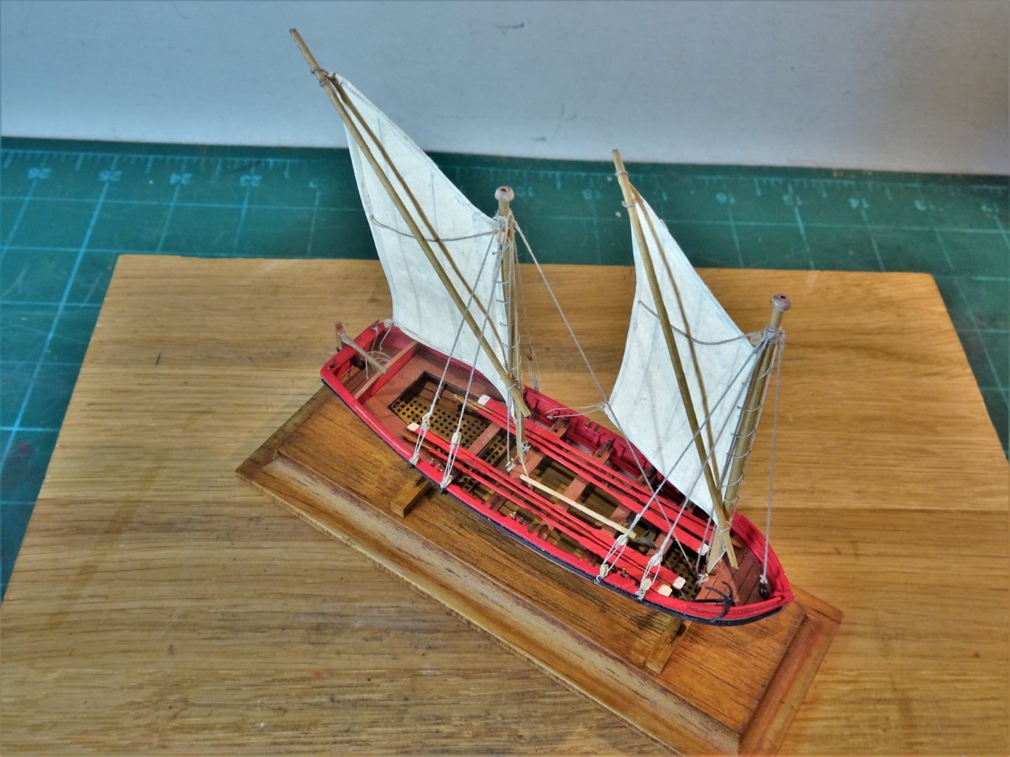
I have entertained myself this week building Chuck’s delightful little mini kit of the double Capstan derived from his HMS Winchelsea kit. 3534(3) At 1:48 scale it won’t unfortunately fit the forthcoming Sphinx build but it will sit in her case as an example of such a device of the mid-18th century. I am ahead of the game in one respect, I have already made the 22’ Yawl which will also be supplied with the kit. 610(2) At least one tiny element of the Sphinx build will be rigged. 620(2) 631 I have already decided to have only the Pinnace displayed on the hull so the Yawl too will sit within the case of the completed Sphinx. B.E. 20/08/2021
.thumb.JPG.7bc7241c3a5c35292fadce6152e5af86.JPG)
.thumb.JPG.87120617121160aa2cae90c33c012d45.JPG)
.thumb.JPG.ab8d124c5490d45d106f8a54652ba36b.JPG)
- 857 replies
-
- 17
-
-
- Sphinx
- Vanguard Models
- (and 1 more)
-
Hi Glenn, I’ve got an A4 sheet of notes to myself of questions and possible mods, but I need to wait until I see the model before I commit to anything. I’m certainly thinking of minimal deck planking and the addition of Lodging knees, Hanging knees, ledges and carlings. On the hull I’ve mused about the possibility of Open hull framing in the area of the Orlop/ lower deck; the kit does include the Orlop deck and ladderway down from the Lower deck. It’s a very exciting prospect, made more pleasurable by the thought that I don’t have to worry about where to put it, altho’ my younger self would probably have masted and rigged it. Regards, B.E.
- 857 replies
-
- 7
-
-
- Sphinx
- Vanguard Models
- (and 1 more)
-
Very nice progress Richard. The absence of lower Quarter pieces at the Transom is problematic, and I couldn't live with it, it just doesn't make sense. I had two nibbles at stern modifications before I was more or less happy with the result, it was however a fraught exercise. It's one of those 'time to bite the bullet moments' in a build. B.E.
- 104 replies
-
- 1
-
-
- pegasus
- victory models
- (and 2 more)
-
Looking good Glenn, I always follow the proper planking arrangements for the first layer, I think it gets you into the rhythm for the top layer. Good training also for when builds such as Cheerful or Winnie are taken on where there is no second layer comfort blanket. 🙂 B.E.
.JPG.09d30498d34e479a7e14a5be2c3ee8fe.JPG)
text.jpg.aa3df9d15257b204f2ec7540f3249e5d.jpg)


.JPG.1b0b73887bba057914031335d463fb4e.JPG)


.JPG.6deddb354cec499ef8c57c70dde30bb9.JPG)
.JPG.80196bb7bb570408c30f80199865b69d.JPG)
.JPG.6846d084b17f1ca28ad9b5a853a729a1.JPG)
.JPG.02c8921cb3ac5f750ea17e2e0ae62221.JPG)
