
HOLIDAY DONATION DRIVE - SUPPORT MSW - DO YOUR PART TO KEEP THIS GREAT FORUM GOING! (Only 51 donations so far out of 49,000 members - C'mon guys!)
×
.JPG.ca33079f5815b861e67b9c2cccd37982.JPG)

Blue Ensign
-
Posts
4,564 -
Joined
-
Last visited
Content Type
Profiles
Forums
Gallery
Events
Everything posted by Blue Ensign
-
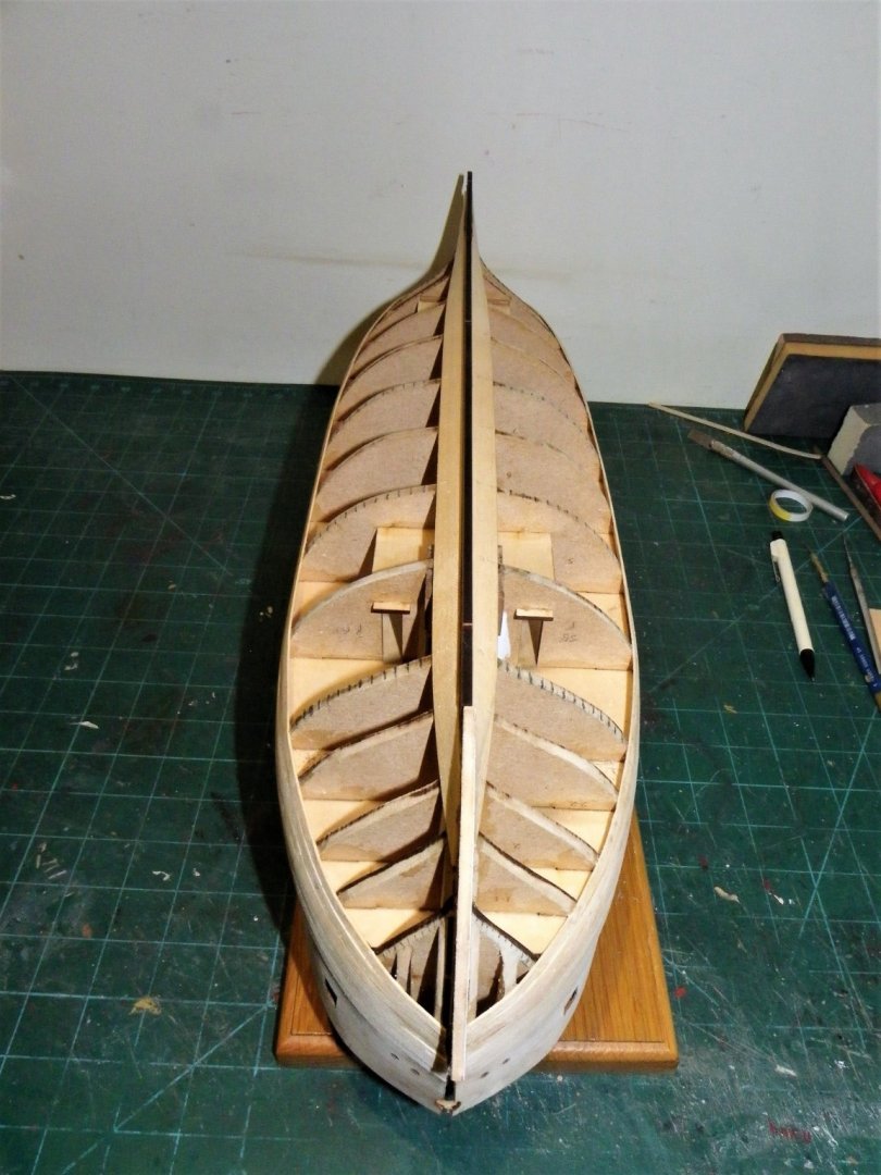
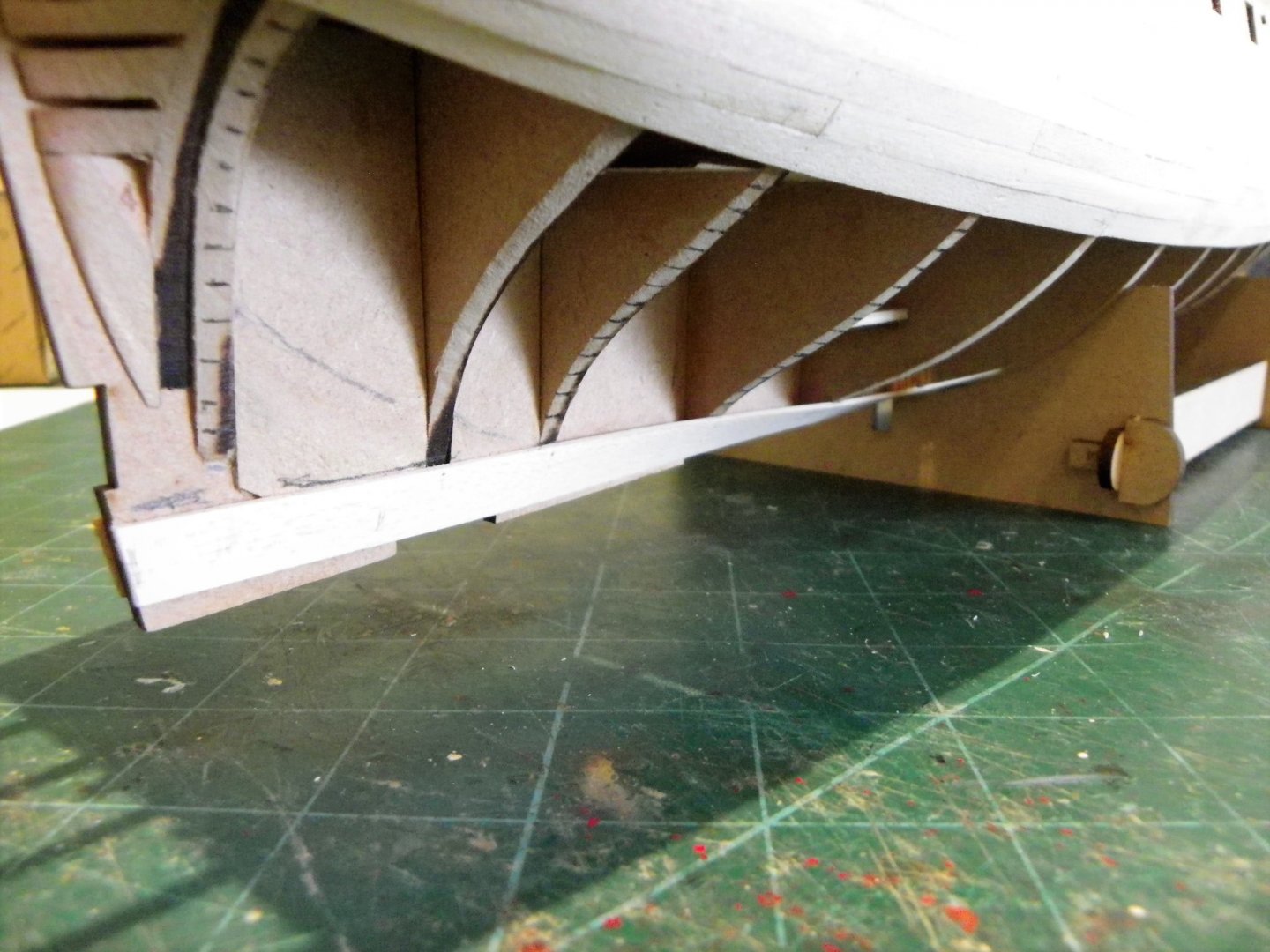
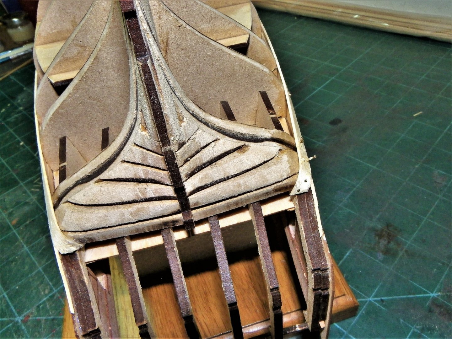
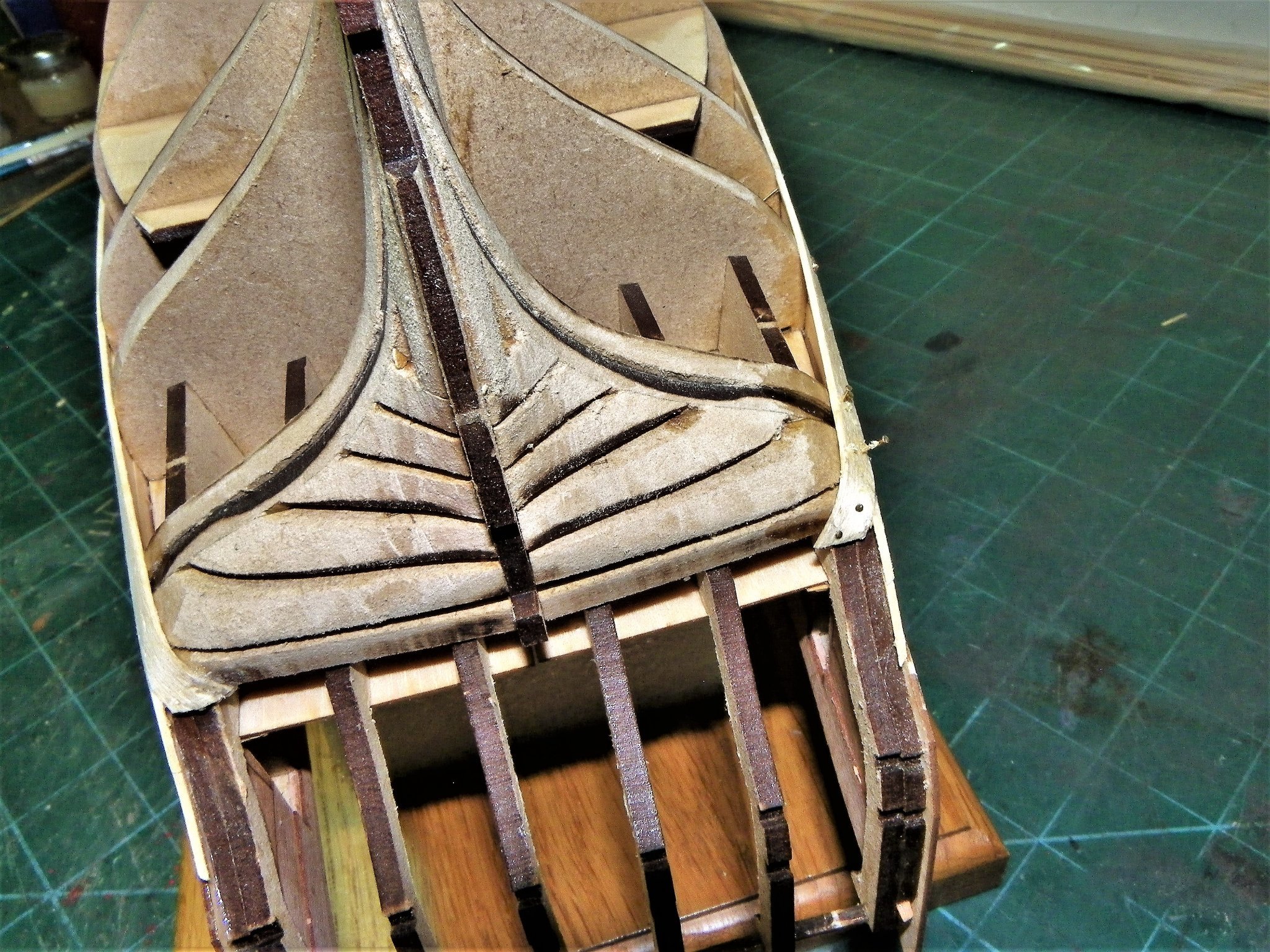
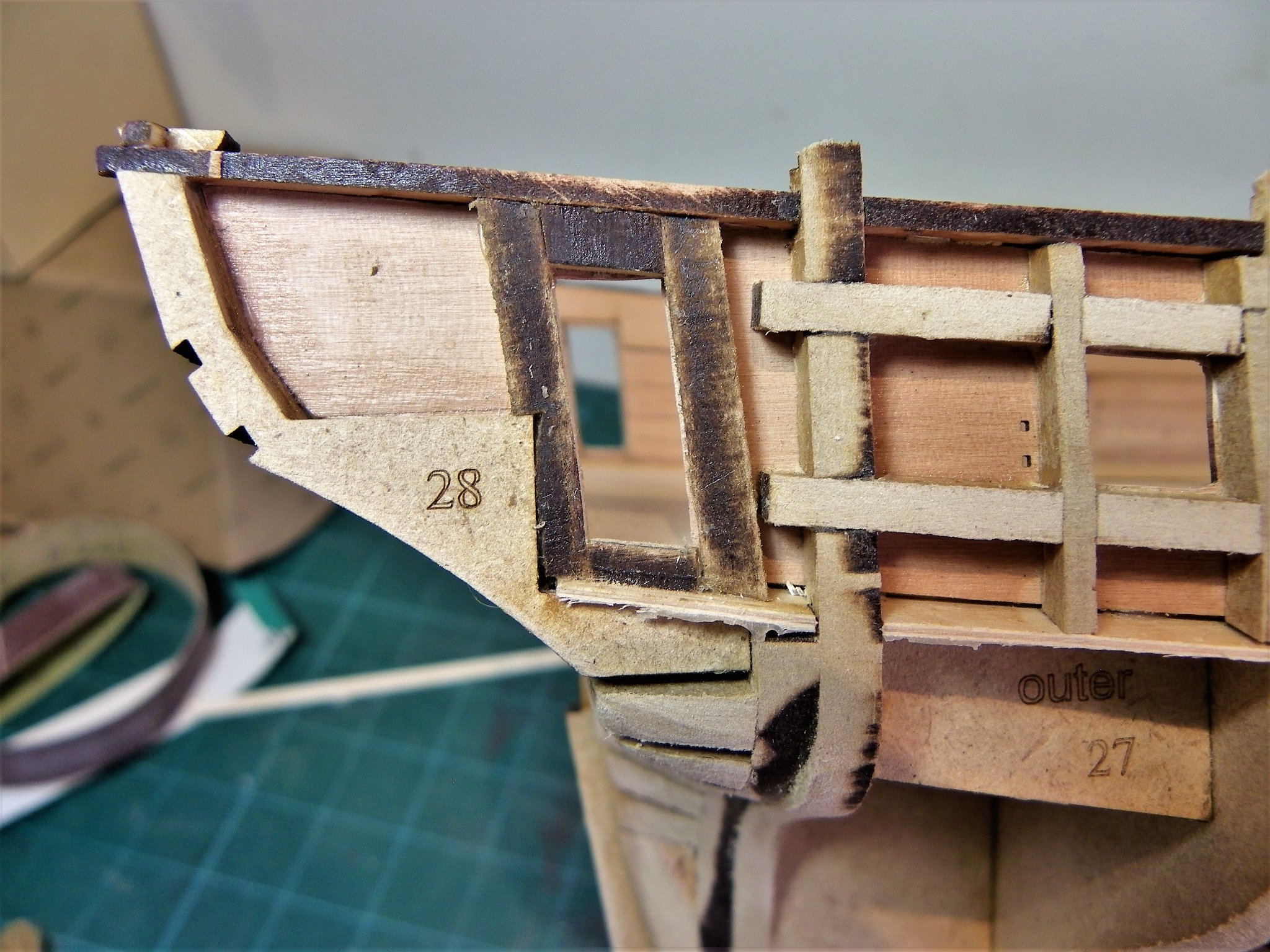
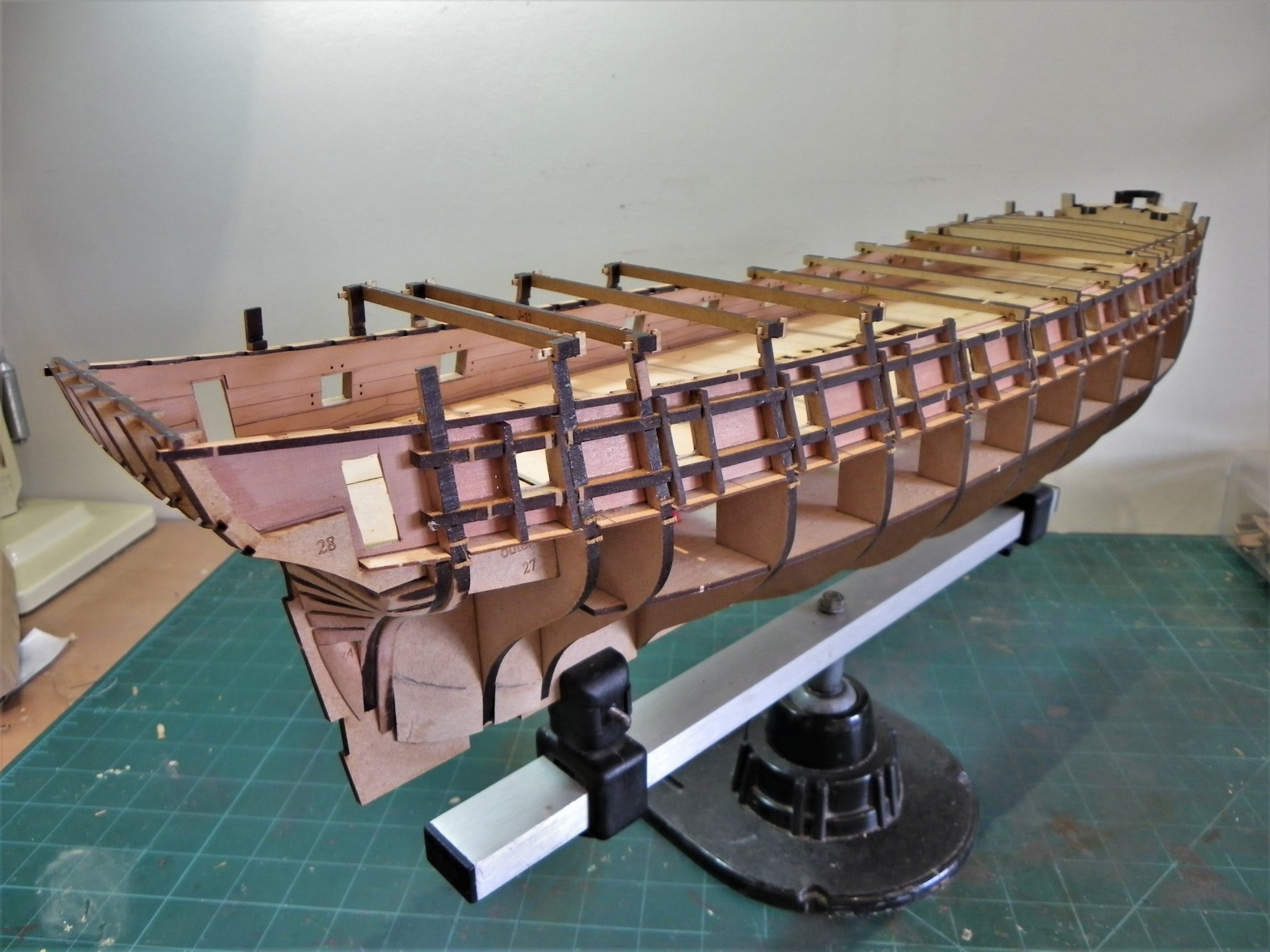
 Post Twenty-four Fitting the Garboard Plank. I find it more difficult to visualise the garboard run without the keel and stem in place, so these are temporarily fitted. 0618(2) I made a dummy stem post for the lower part to better gauge where the Garboard plank should start at the forward end. It seems to me that certainly for the first planking, this really means running the plank to the very outer edge of the false keel and shaping to match. 0622(2) I decided to use a 10mm wide strip of Limewood for the Garboard, a sort of Garboard plus. I keep a small supply of 6mm, 8mm, and 10mm wide strips, always useful when it comes to spiling. 0633 I left the aft end of the plank to run naturally as it will need faying down to nothing towards the keel. 0623 The twist as it meets the flat of the keel is evident here. 0630(2) The position at the bow doesn’t look too bad to my eye. 0625 How this will work out in practice remains to be seen. The maximum number of full width planks remaining down to the keel is now 14. So, it’s down to using a tick strip approach to fill the remaining space. B.E. 11/10/21
.thumb.JPG.722d442ce36d8602cba5eccc6b684575.JPG)
.thumb.JPG.348f079c6db653457799a9a9c58d3676.JPG)

.thumb.JPG.5d4e1548b03fa870a2fcaf59a3954774.JPG)
- 857 replies
-
- 18
-

-
- Sphinx
- Vanguard Models
- (and 1 more)
-
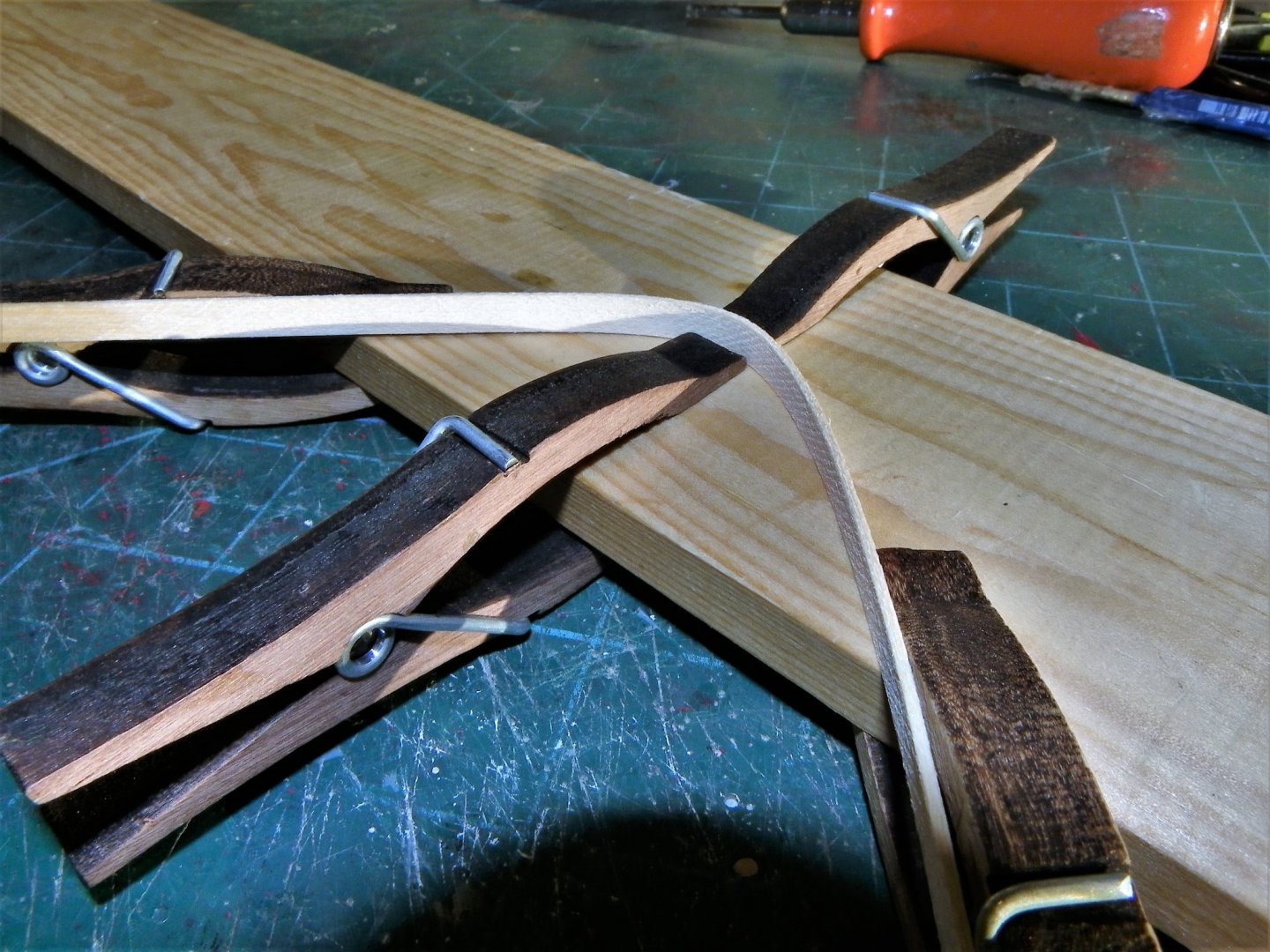
Thank you Paul, Mark, Bob, and Glenn(UK) @ Glenn- Once I have shaped the planks, I re-fit them (dry) using pins and clamps. The hot air does indeed reinforce the bend, there is always a little spring-back particularly with edge bends. Regards, B.E.
- 857 replies
-
- 2
-

-
-
- Sphinx
- Vanguard Models
- (and 1 more)
-
Hi, bitter, Beyond using it on Cricket bats I avoid Linseed oil like the plague in relation to modelling. It can be quite sticky and take an age to dry, I would be very wary of using it, certainly on a completed model. I did include a list of the items and sources at the end of my log, Richard has given the reference in his post. As regards the colour of the topsides, Black was the official colour for British ships contrary to the nice shade of blue shown on so many contemporary models. Regards, B.E.
-
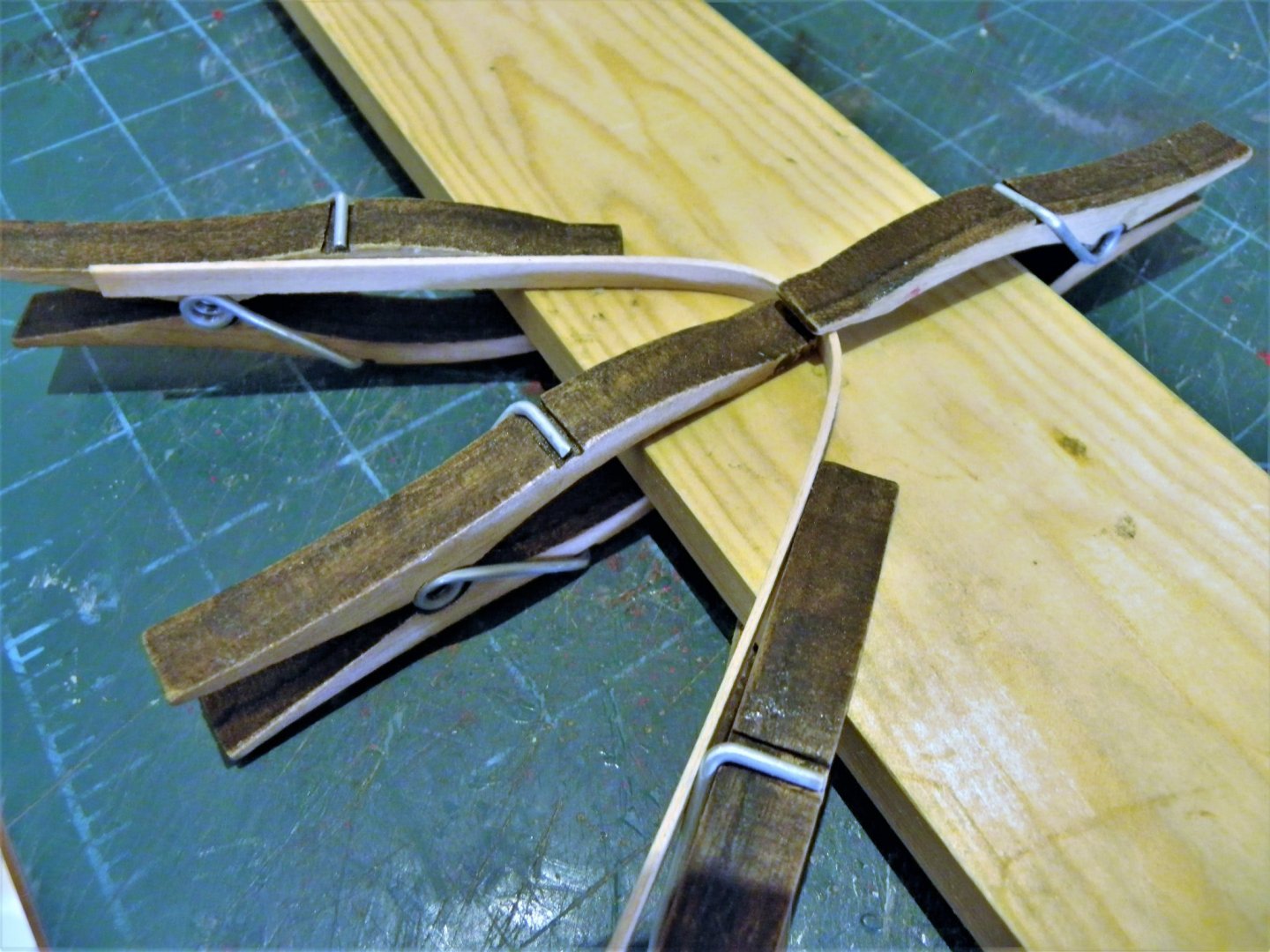
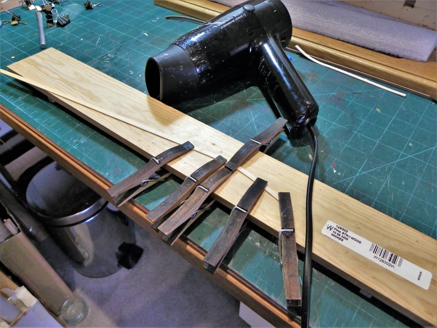
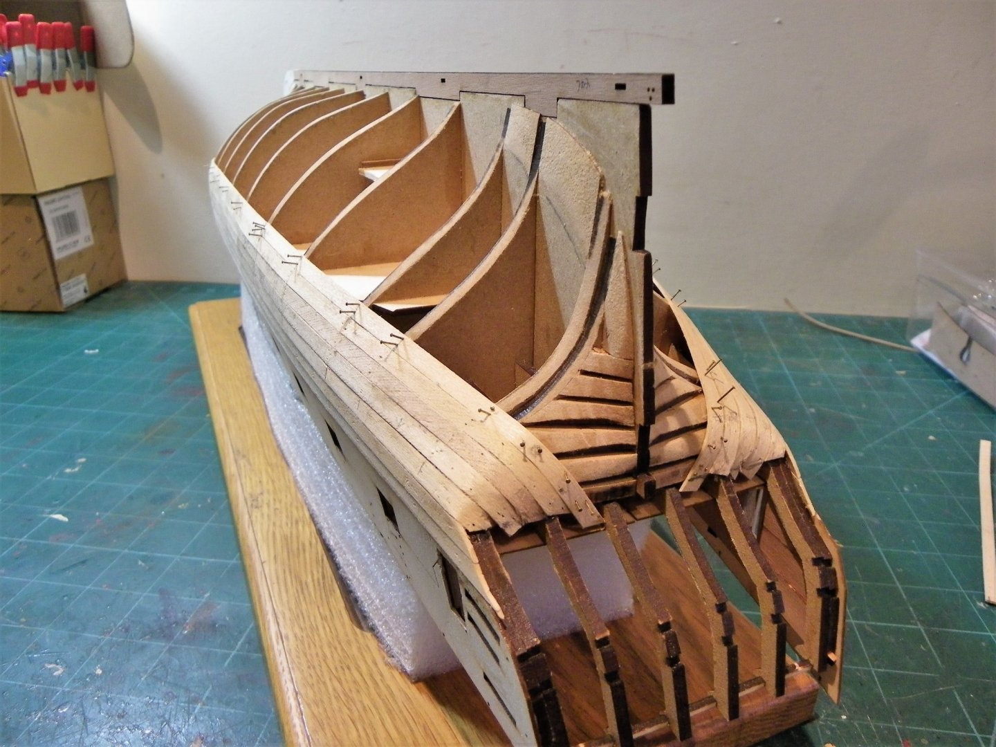
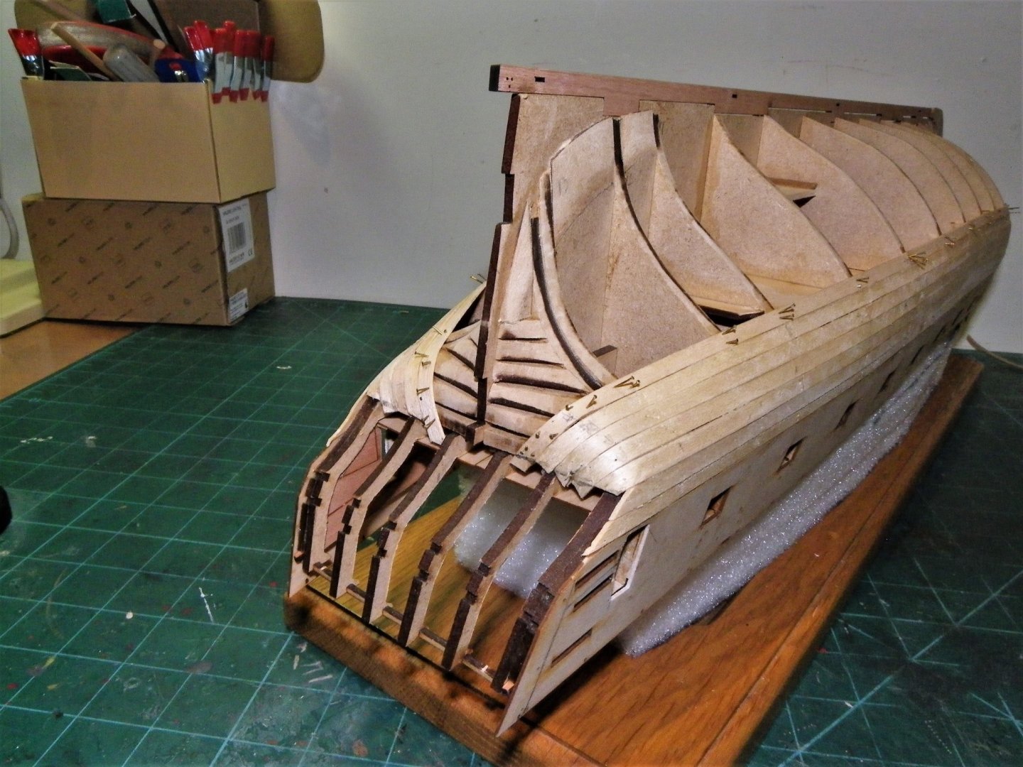
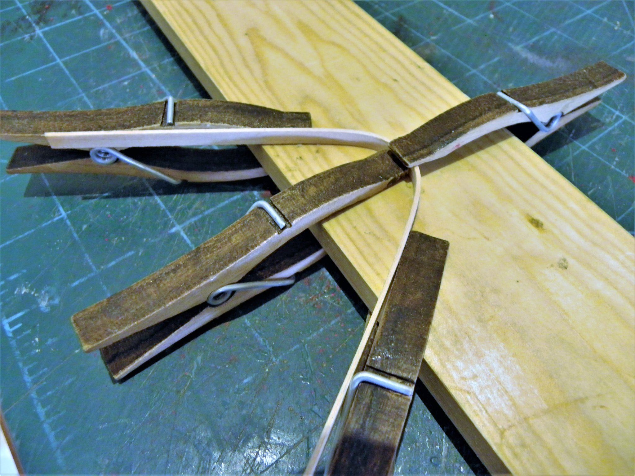
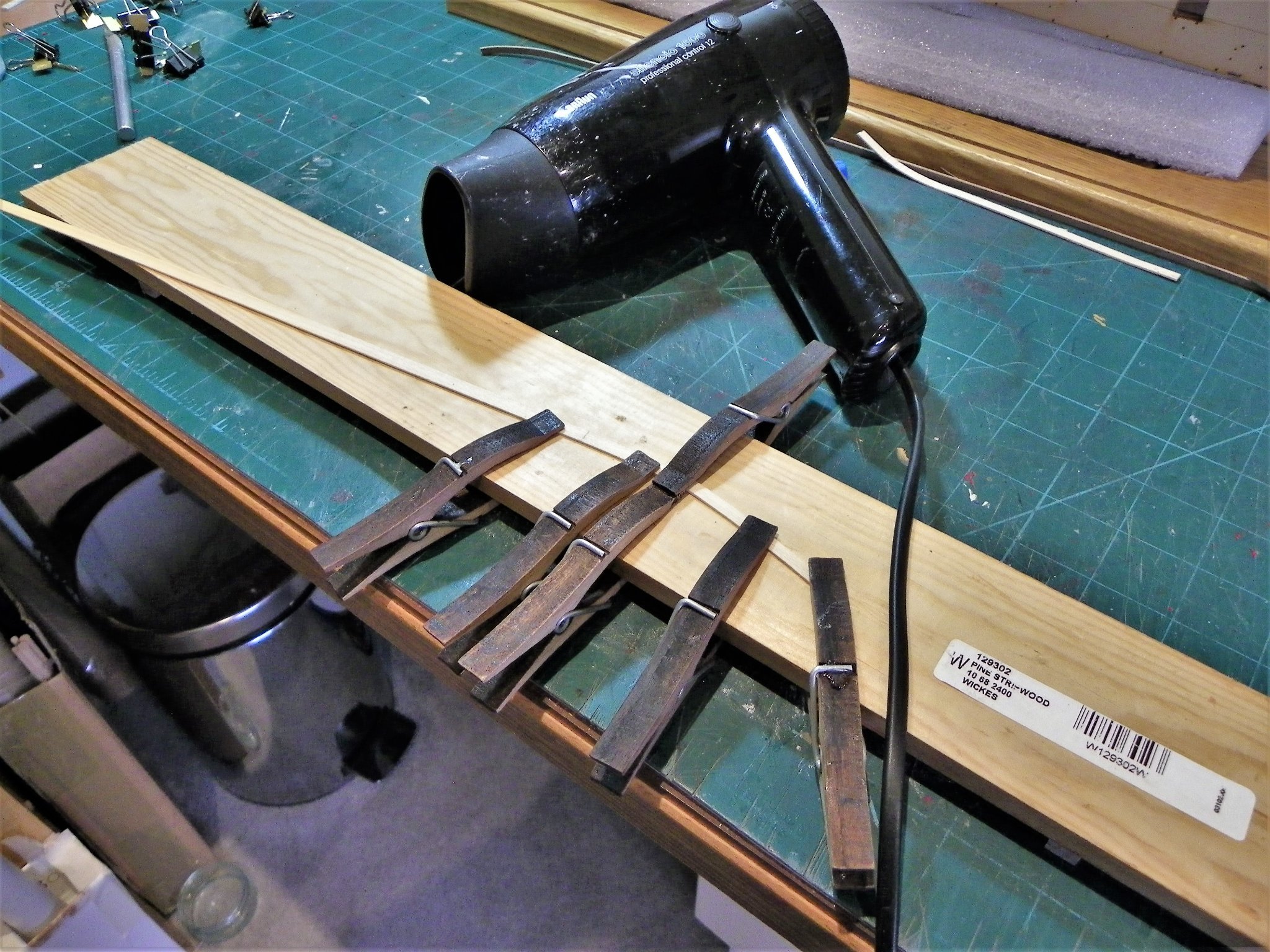
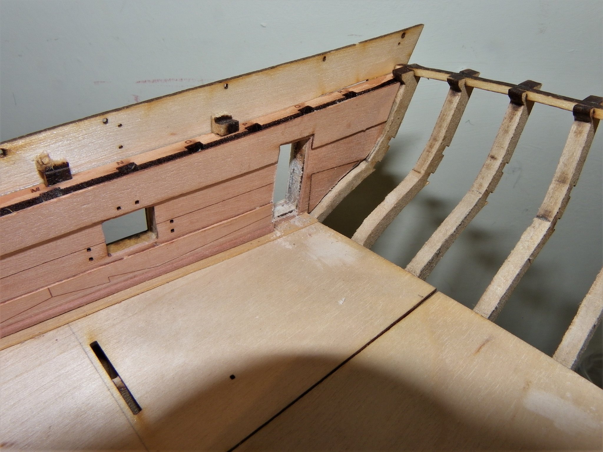
Post Twenty-three Planking down to the lower deck and stern counter. I decided that a simple approach of taper and edge bend was sufficient for the next four strakes which take me down to just below the lower deck. The taper applied is modest, only reducing the plank width at the stem to 4mm. 0578 I’m very much old school and prefer to use the wet and heat system of plank forming. Only requirements a long plastic tube for soaking, and an old hairdryer donated by Mrs W. In summary: Mark the taper, soak, cut taper, mark edge bend centre, (where applicable) form bend, apply heat, pin, and glue. 0574 I work the strakes singly, Port and Starboard, matching the bow tapers as I go. With Sphinx, the tricky part is to get the sharp bend up to the counter as neat and smooth as possible. 0580(2) All the stern strips are separate and staggered along the bulkheads between the stern and b/h9. 0573(2) The bend didn’t prove too difficult to form and should be easier with the thinner Pearwood strips of the second planking. 0584 0586 Once the planks are formed I test fit them using clamps and pins before gluing, applying a blast of heat with the strips in place. 0599(2) 0597(2) I’m taking things at a leisurely pace at present, other stuff to do, so fitting the four strakes each side has taken several days. 0602(2) 0603(2) 0608(2) 0615(2) Moving onto the Garboard…. B.E. 10/10/21
.thumb.JPG.0a79d3c004a4f9096ad852bd359a1f12.JPG)
.thumb.JPG.21954ac4f23ee1280f20f1b9df5da0b7.JPG)
.thumb.JPG.872e3a612ebd07eb1c85ba8e6620cc21.JPG)
.thumb.JPG.98c9947af46a382671d09c4b849546a7.JPG)
.thumb.JPG.93072d6bdb85e876d1639dee3a60d33d.JPG)
.thumb.JPG.34eb5eb480ff3ad77ddd0de8f6183c29.JPG)
.thumb.JPG.b0e140b73836f0883b0359144f857a39.JPG)
.thumb.JPG.df888ee63f0c28a19b1260524948fd8a.JPG)
- 857 replies
-
- 29
-
-
- Sphinx
- Vanguard Models
- (and 1 more)
-
Hi Allan, I got the information from the the Book Old ship figure-heads & sterns by L.G. Carr-Laughton. He was a founder member of the Society for Nautical Research, and editor of the Mariner's Mirror. His book is a hefty tome and well worth having. My copy is a Conway Maritime Press Limited edition published in 1991, altho' the original was published in 1925. Regards, B.E.
-
The order for ships to have names on their sterns was issued in 1771. The names were to be painted on the second counter in letters of 1 foot high and be enclosed in a compartment. Oldies will remember that Victory had her name in a cartouche on the stern for many years. In 1772 the order was amended, letters were now to be painted without a compartment in letters as large as the counter would permit. (Victory now has that format) In 1778 Admiral Keppel had the names rubbed out on his fleet, but that only applied to one campaign during that year. The large letters continued until after Trafalgar, but according to LG Carr-Laughton, in the closing years of the war apparently the name was painted small in a little compartment; and not long after the peace was entirely omitted. Museum ships of the post Napoleonic era don’t always adhere to this arrangement. The following ships all have their names on the stern; Trincomalee 1817, Unicorn 1824, Warrior 1860, Gannet 1878. In relation to ships of the 1770's I would certainly include the name on the counter. B.E.
-
Some nice detailing there bitter, glad my build was of use to you. One thing that catches my eye are the chainplates to the Main Channels; they seem to have a reverse angle rather than being angled slightly forward or vertical. I recall that I had to modify the kit etched items to fit on my build. At your late stage in the build I’m not sure how to proceed with any hand applied protective coating with all the fittings in place, makes it tricky to get an even application. Perhaps you can use light coats of a spray matt varnish overall, having removed all dust. I think this is an approach taken by some modellers, but one I've not tried myself. With decks I would scrape them (not sand) to a smooth finish and apply a coat of flat matt water-based varnish such as supplied by Admiralty paints. This would be done after fitting the coamings of the hatchways but before any of the other fittings were installed. For the hull planking I would use a wipe-on-poly, but this would also be done before the addition of fittings. B.E.
-
Neatly cut scarph joints starlight, and your stove looks excellent, well done. B.E.
-
One of the consequences of being a 'pathfinder' Glenn. At least you have alerted members to this potential issue, and James gives good advice; If everything isn't looked at stages ahead to check for any effect of impact, then you can't retroactively push yourself to the point where everything will align. This is a critical area of any build, I hope you get it sorted. B.E.
-
My copy arrived earlier this week, and I agree with your comments Mark. A lot of book for the money, and well worth the wait. I can see where Chuck got a lot of his inspiration from for his Royal barge and Longboat models There is a great section on Barges. B.E.
-
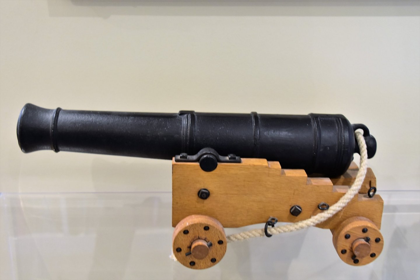
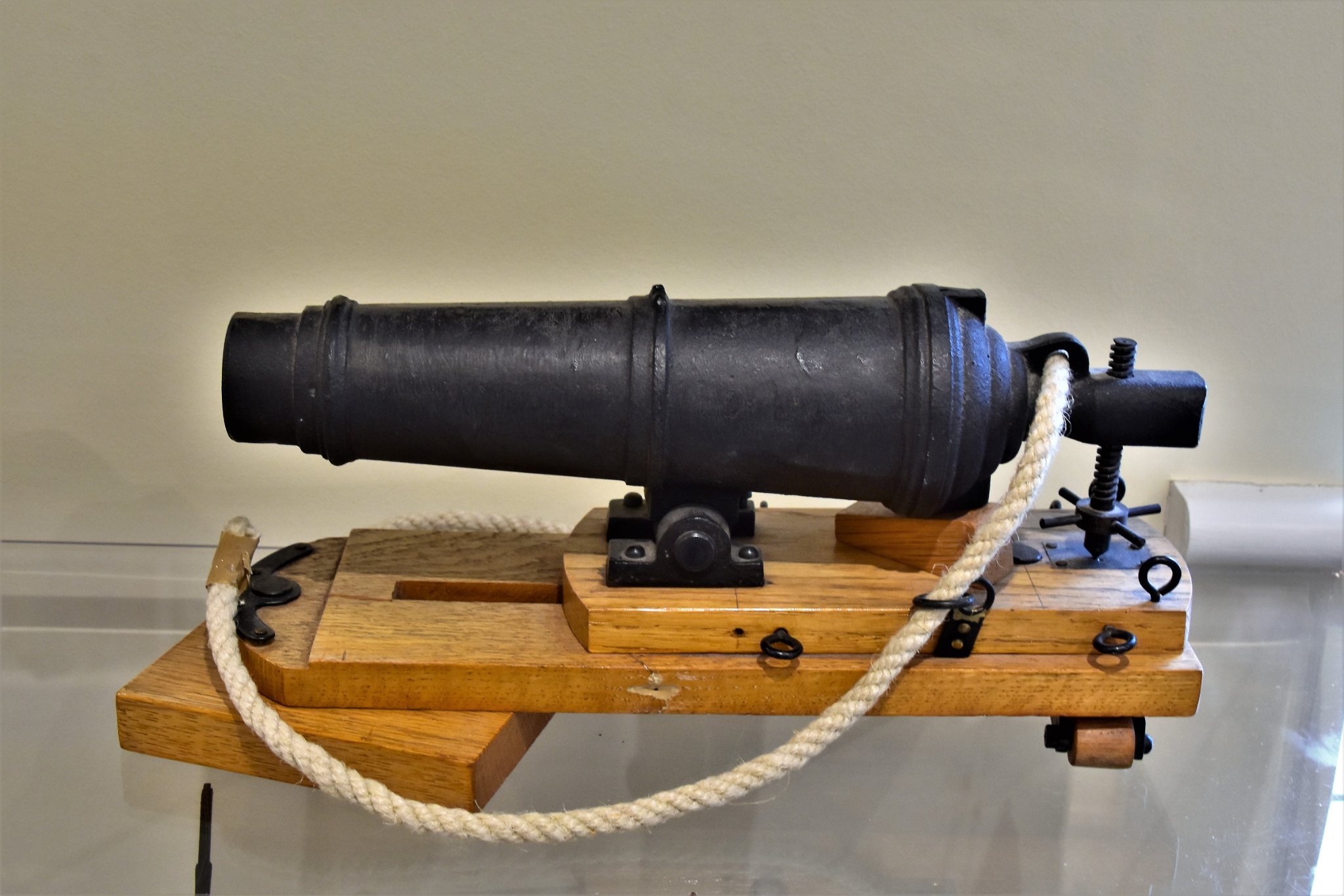
There surely is, but not one I made. Together with a 24-pounder long gun I found it in a small village shop many years ago. The barrels are cast iron and the woodwork Oak. Nice items and very heavy, not sure of the scale but the long- gun barrel is 15½” muzzle to button, and the Carronade 11½” The Breeching ropes I made myself at The Chatham Naval Dockyard on their demonstration ropewalk. B.E.
.thumb.JPG.c2e53bcccceccfdb1e79bbc2e6bf12a3.JPG)

.thumb.JPG.f4f41296d915f36da5cb53561e2ec33e.JPG)
- 857 replies
-
- 11
-
-
-
- Sphinx
- Vanguard Models
- (and 1 more)
-
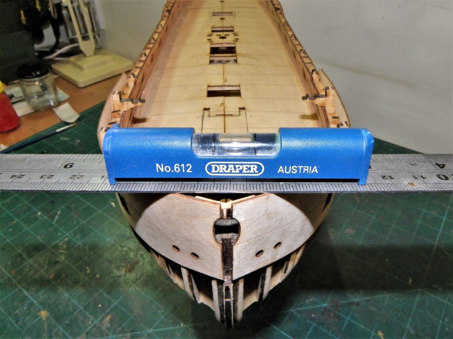
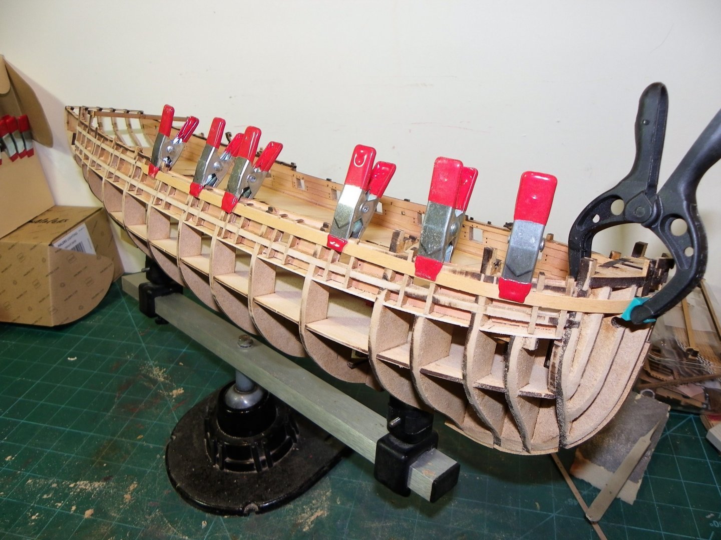
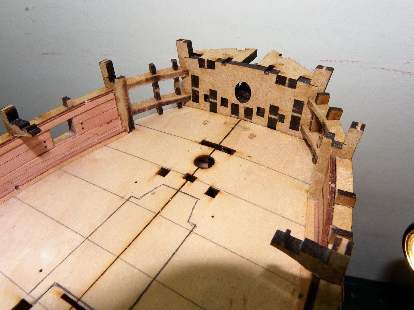
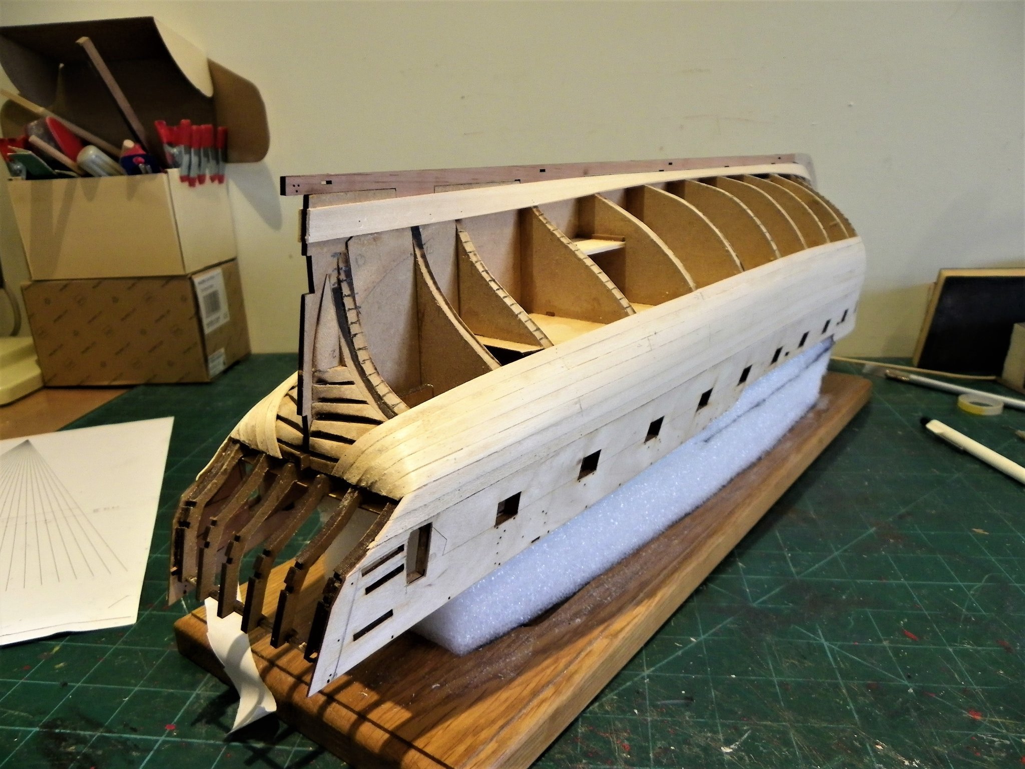
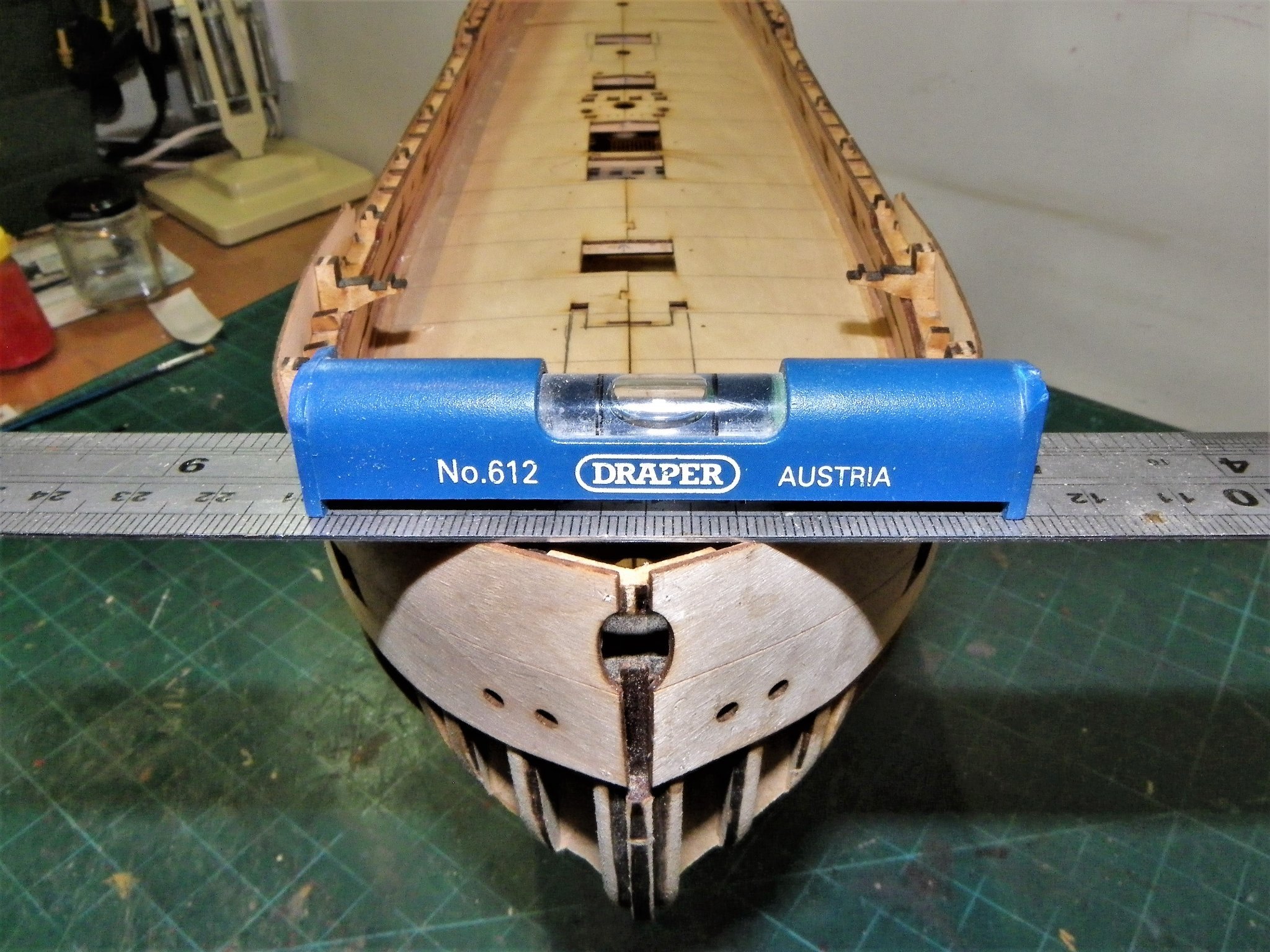
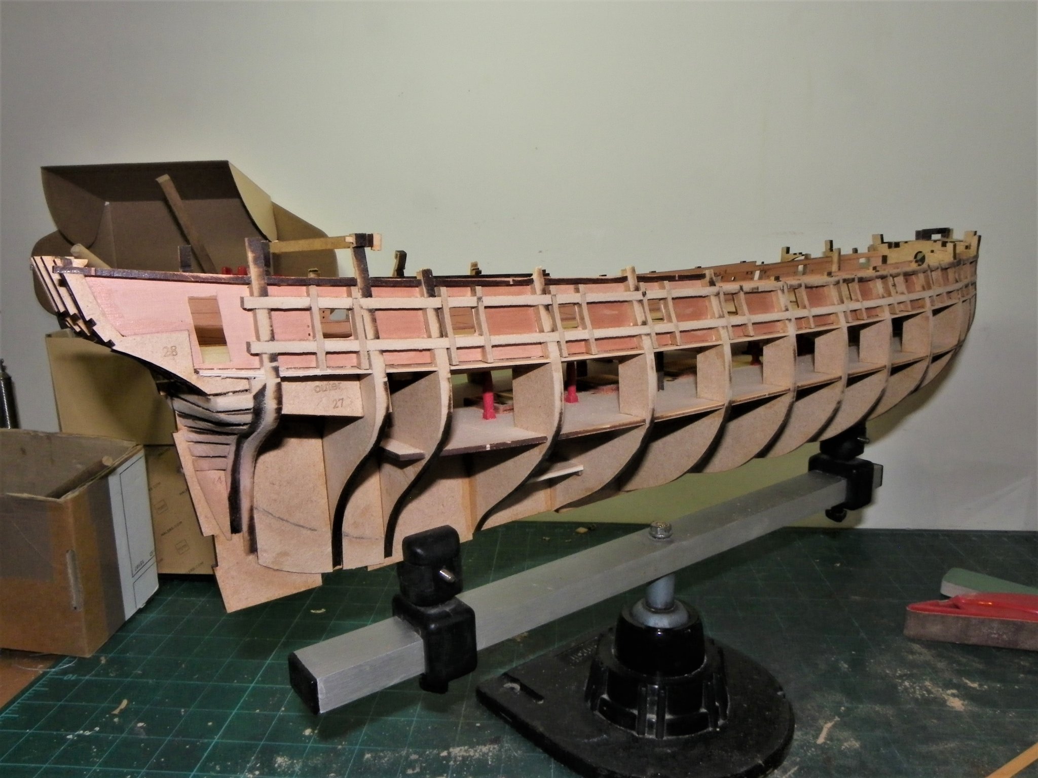
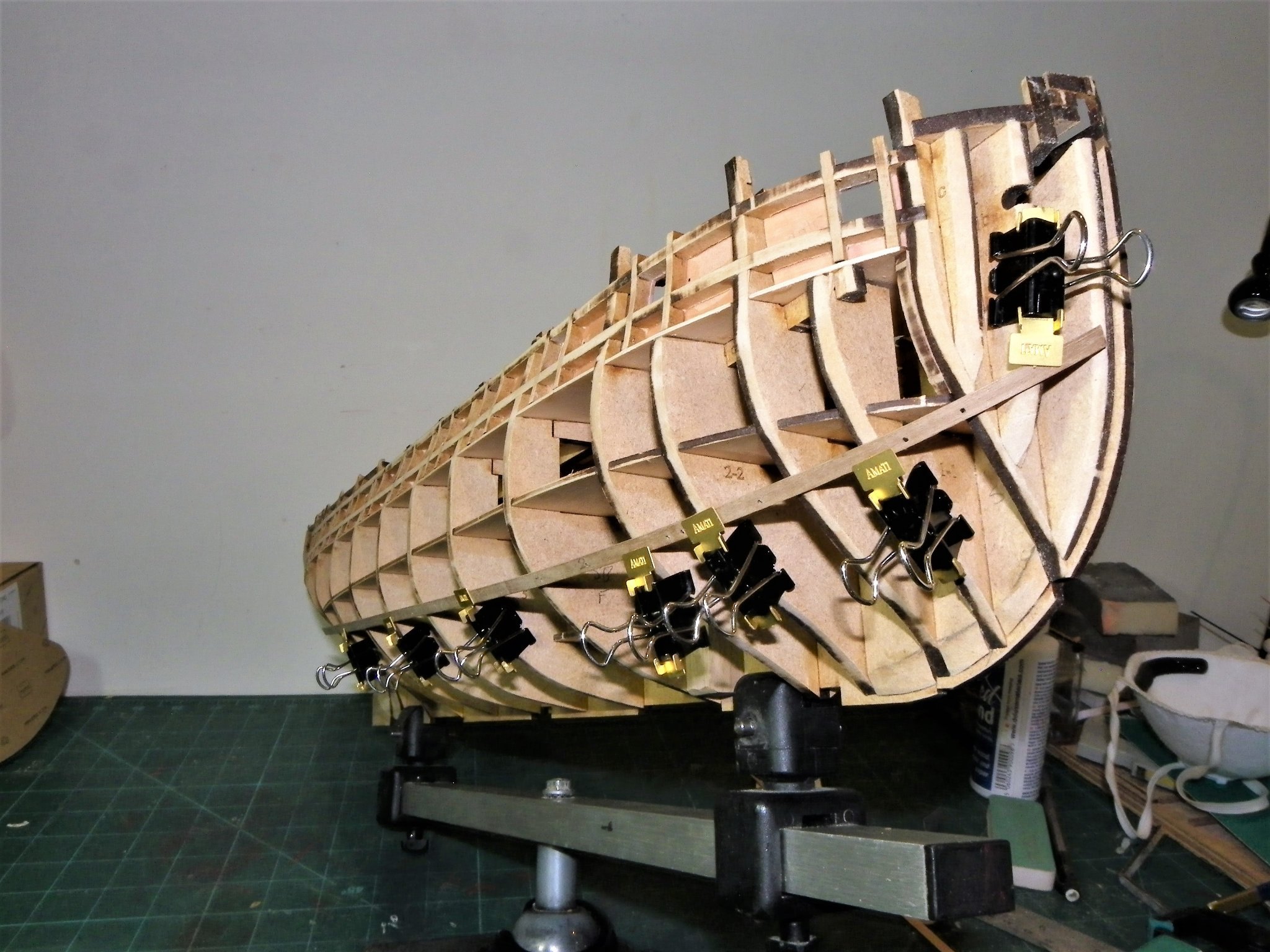
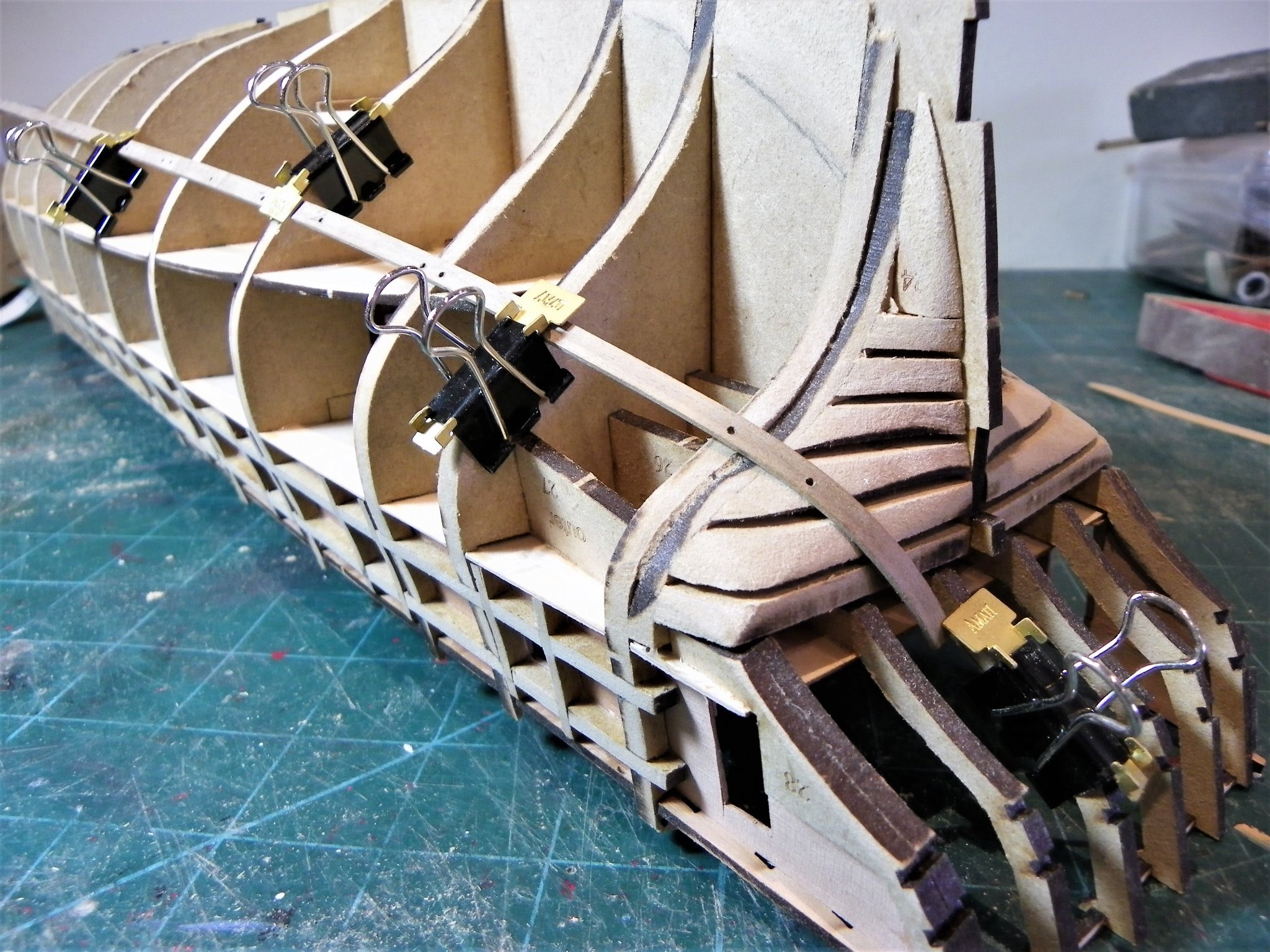
Post Twenty -two Hull Planking begins. As per the manual I start with three strakes of planks, which I pre-fit and heat to take the stress out of the bow curve. They are then glued and pinned until set. 0532(2) I start at the bow and progressively glue and pin along the hull. 0535(2) The lowest of the three strakes I terminate three bulkheads from the stern as this requires a tight bend up to the stern lower counter, better managed as a separate section. 0540 The plank is pre- bent using water and heat and the bend needs to be made from a much longer plank to avoid harsh angles or splitting. 0566 With the three strakes each side fitted, for this first layer I will follow a modified tick strip approach, and the first stage is to work out the plank runs and determine the width of the Garboard plank. Before I start planking I need to devise a method of securing the hull both upside down and the right way up. I do a lot of planking with the hull inverted. The Amati keel clamp is useful for holding the hull at angles for specific jobs, but not so good for planking. My ageing version has an alarming habit of suddenly lurching to either port or starboard. 0546(2) For holding the hull inverted I found some stiff packing foam, cut to fit within the hull. 0561(2) This sits down on the deck and holds the hull firmly but gently. 0543(2) For sitting the right way up my old Cheerful build board is a good match. 0544(2) Once the keel, stem, and sternpost are in place a further design of board will be used. Moving on….. B.E. 02/09/21
.thumb.JPG.10b5f564ef0e299828dc6a567344a956.JPG)
.thumb.JPG.7ced2e98bc05c3e7366b1a9e70887eac.JPG)
.thumb.JPG.ddec28e4e999ef91b02c89d2643ea77d.JPG)
.thumb.JPG.23c3aaa2040baa398d3653d699cc3272.JPG)
.thumb.JPG.19af1fc42ce90cdae59147aa41ac1ac3.JPG)
.thumb.JPG.56ac878f2d9322342d77f5ed99e64cc7.JPG)
- 857 replies
-
- 18
-
-
- Sphinx
- Vanguard Models
- (and 1 more)
-
Hello Admiral, I have looked back at my build notes and this is what I wrote at the time. The side colour For this model I wanted to achieve that mellow golden look between the wales that is representative of ‘bright’ sides ie payed with rosin, as seen in many marine paintings contemporary to the period. After some trialling I decided upon Humbrol Matt Cream (103) as the base coat. Once dry I coated it with white shellac, which dries very quickly, and then over-painted with mellow pine wood dye. This may seem a little unorthodox to many model painters, but I obviously tried out the operation on a spare plastic hull before committing to the real thing. I think I have got close to the colour I am after. The Wales and Topsides are blackened, (Humbrol 33) but I have reduced the black paint by the addition of quite a proportion of sea grey (Humbrol 27) to give a finish several shades less than the original black. Overall this is not as complex as Victory to paint the broadsides as the strakes follow the lines of the wales, but the Topside mouldings do take a little careful masking given the smaller scale. Inside the hull halves the bulwarks were painted Red ochre – what else, much easier done before assembly as the tumblehome restricts access. On the subject of air brushes, I have little to say. I prefer to hand paint model ships, I think it gives a more natural look. Regards, B.E.
- 126 replies
-
- 3
-
-
- le superbe
- heller
- (and 2 more)
-
No mean feat to find a builder these days, and the materials to do the job, hope it all goes smoothly Chris and you're soon back up to speed. Exciting time tho' B.E.
-
Thanks for looking in Admiral. I scribed three lines of planking between the ports using a styrene strip as a guide. The scribing was done using a curved dentists probe altho’ I think Tamiya make a plastic scriber tool. I also scribed the wales in the same manner. Hope this helps. B.E.
- 126 replies
-
- 3
-
-
- le superbe
- heller
- (and 2 more)
-
Very kind of you Glenn, the jobs yours, what address shall I send it to.😉 ... and the first of course is the fairing. B.E.
- 857 replies
-
- 1
-
-
- Sphinx
- Vanguard Models
- (and 1 more)
-
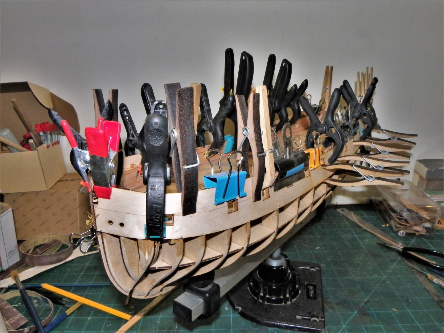
Post twenty-one After Fairing The blurb now indicates that the Upper Hull patterns are fitted to the hull. Before I do this I need to think about what is required to further modify the stern end to open up the Quarter galleries. 0471 Firstly, the casings are added for the QG door which I had previously cut out on the internal bulwark pattern. 0476 These are easily fashioned from the 4mm mdf bulkhead fret. The patterns are pre- bent around the hull as indicated; accurate positioning is essential before marking the opening. The doorway is then cut out on the Upper hull pattern by drilling a series of holes around the edges and using a scalpel to make the cut. 0479 I used my entire stock of clamps to secure the pattern around the hull, plus fine pins along the lower edge. Gluing the patterns was a bit like plate spinning, getting the pattern in position before the glue starts to set while ensuring that the gunports are all lined up with the frames. 0490(2) I was pleased that the port cut-outs were a good match to the hull framing and the patterns met uniformly at the bow. 0492 0510 I was slightly thrown by the manual build photo (136) which appeared to show the slot for the upper pattern for the Quarter gallery above the level of the internal framing. 0502(2) Plan sheet 8 does however, show the top line of this slot level with the stern framing. 0517 The doorways will be cleaned up later in the build. 0499(2) A milestone of sorts is reached. I will leave any internal detailing, including deck laying, until the hull is planked. So, onto my second least favourite modelling job. B.E. 28/09/21


.thumb.JPG.3327d0cdc9e7ae9334d2d093835eb429.JPG)
.thumb.JPG.1d04bb460dcbf5b90fca532992ded66b.JPG)
.thumb.JPG.57f9cd7a2367f240c91c699fd01b30fa.JPG)
- 857 replies
-
- 20
-
-
- Sphinx
- Vanguard Models
- (and 1 more)
-
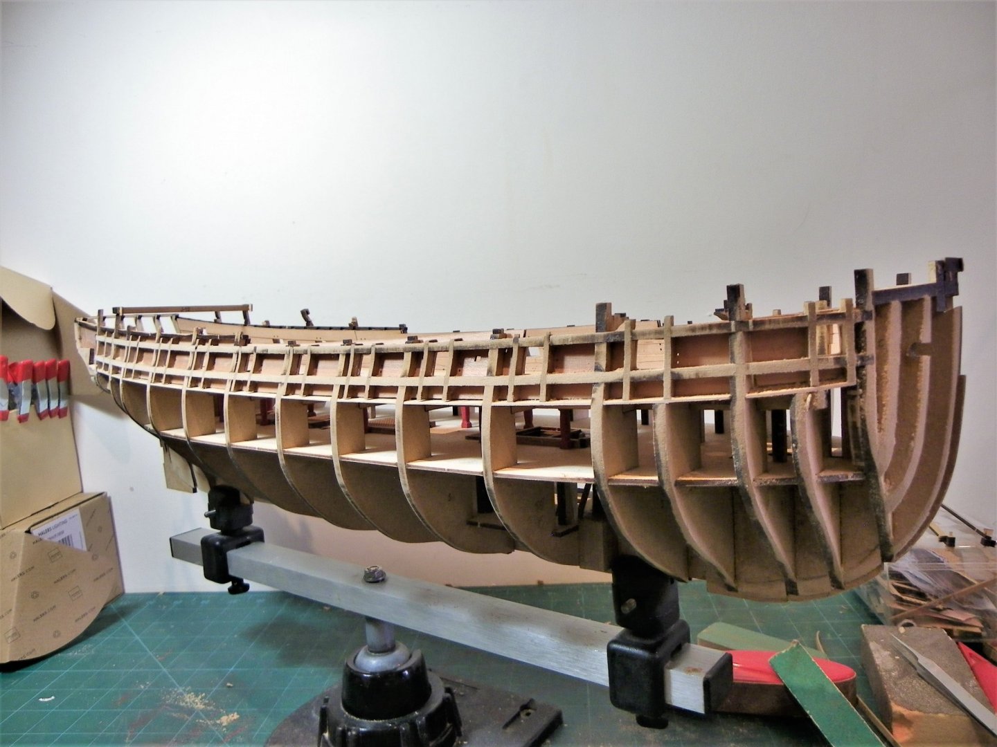
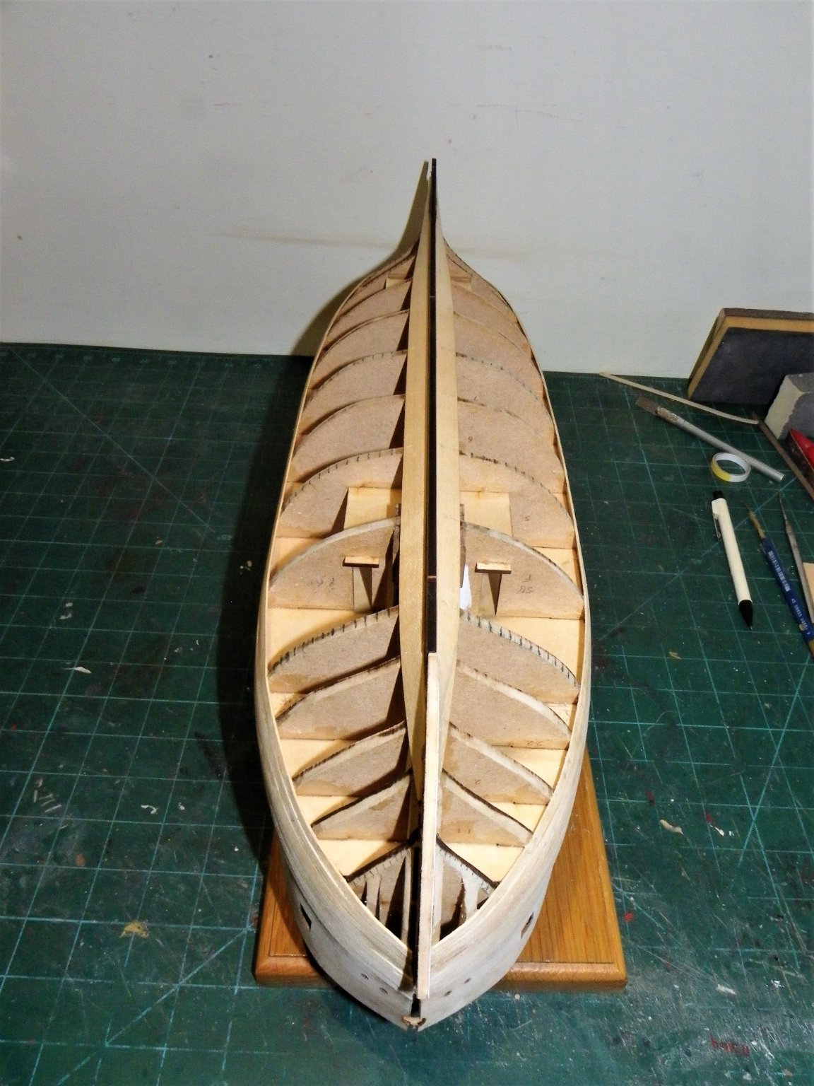
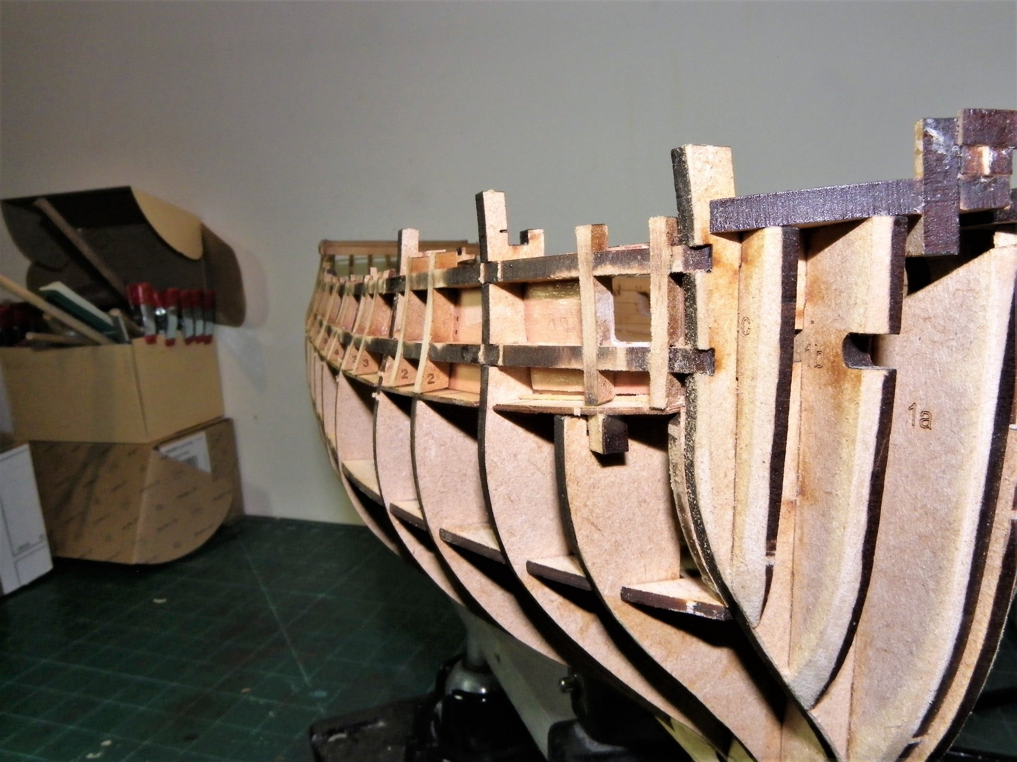
Post twenty That fairing business Looking at the hull, the topsides have a subtle and rather elegant concave shape to the bulkheads and gunport frames. On my model the gunport frames stand a little proud of the bulkheads, and I am concerned not to alter the shape of them. 0437 My first task is to sand the vertical gunport frames in the vertical plane, flush with the bulkheads. 0440 I then sand the longitudinal frames. At this point you will see that all but one of the aft bracing jigs has broken off. 0445 Finger Sanders are used for this job. 0442 I then move onto sanding the whole side down to the point where the char is removed from the bulkhead edges. For this I use the coarse side of a soft sanding block, moving along and downwards. 0447 I am now starting to use a test plank to check along the topsides. I check at different points down to the Upper deck level What I am looking for is any indication of lumps or depressions as the plank passes across the bulkheads. Moving on, below the lower deck, fairing the bulkheads continues. Bulkheads 5- 7 only need the char removing, from 8 aft the chamfer increases as with from 5b forward to the bow. 0456 0458 0461 Again, a test plank is constantly used to check that full contact is made across all bulkheads. 0468(2) 0470(2) I’ll faff around with this for a while yet, or at least until my patience wears out, but time spent on this not particularly enjoyable phase of a build does pay dividends later on. B.E. 29/09/21


.thumb.JPG.90be709c4083d214dbae1aea8ec8b0a6.JPG)

.thumb.JPG.294f6750403deef8d354b648f2b3caad.JPG)
.thumb.JPG.fa4d19d0112a968455e1134741def309.JPG)
- 857 replies
-
- 20
-
-
- Sphinx
- Vanguard Models
- (and 1 more)
-
I do have a question which I've not been able to sort out. Do the wales stand proud of the planking? Should they? I've looked at everyone's build and can't tell from the photos posted. I've looked in the manual, the on line builds, and all the drawings and can't tell. I'm also asking this James' prototype log. It's just nagging at the back of my brain. I think it does Mark but only by the width of the pattern, 0.6mm. Have a look at the manual photos on page 40. I checked out the cross section plans in the AotS Pandora book which I think Chris used extensively in his design, the wales do stand proud of the other planking, but not by much. I think Chris has also included a pre formed 'Black' strake which sits above the wale. On the Pandora plans this is shown as narrower than the wale but a tad thicker than the planking above. I had a look in my David Antscherl ffm on Swan Class sloops regarding the relative planking differences. What we are interested in are the scale differences, this works out at 0.4mm between the wale and the black strake/ topside planking, and less for the planking below the wale (0.2mm) This shot of James's fine build shows the definition a little clearer. B.E.
.thumb.jpg.fc1362e3e1d4757f062936b666d2efe0.jpg)
- 505 replies
-
- 9
-
-
- vanguard models
- Sphinx
- (and 1 more)
-
Thanks Jacek and Mark, it's reassuring to know that others have not experienced any issues, just as well, I have broken two in the early stages of sanding this morning.🙄 @ Kirby. Kind of you to say so Kirby, but I’m just an enthusiastic amateur whose knowledge of the subject is not always matched by the ability to reproduce it in wood. 😄 If it’s a pro you’re after then look no further than Chuck and there are quite a few others whose work I can’t hold a candle to and follow as my guidance. Modifying kits does add a deal of interest for me and keeps my brain active, but the important word here is ‘fun’ if you’re getting pleasure out of it, its doing you good.🙂 Sermon over, back to the sanding. B.E.
- 857 replies
-
- 5
-
-
- Sphinx
- Vanguard Models
- (and 1 more)
-
Mark said. BTW, for those building the Sphinx, don't toss the wood after removing the parts right away. Hang onto it until the removed parts are sanded, shaped as needed, and installed. I found if I break one, and I have done that, that the piece where the part was removed is an excellent template to make a replacement. Good advice Mark, I always keep the frets until the build end, and in the case of the 'expensive' wood frets I retain them not only for templates but as material for modifications to the model. They are too useful to throw away. Your fairing looks to be coming along nicely. 👍 B.E.
- 505 replies
-
- 9
-
-
- vanguard models
- Sphinx
- (and 1 more)
-
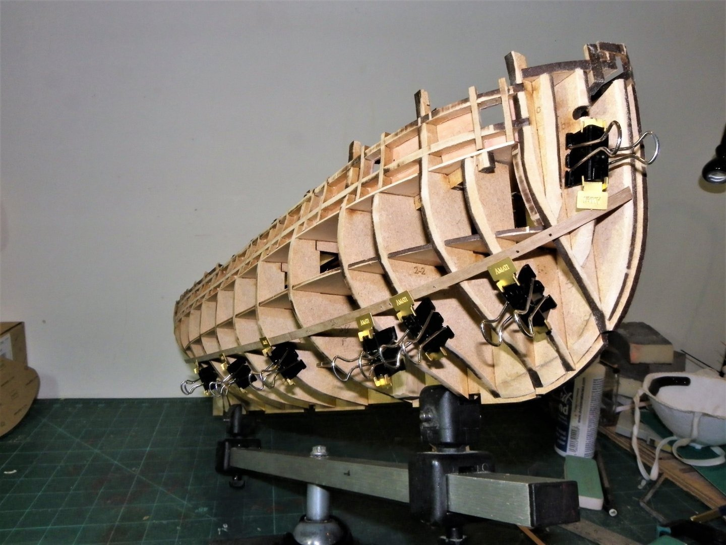
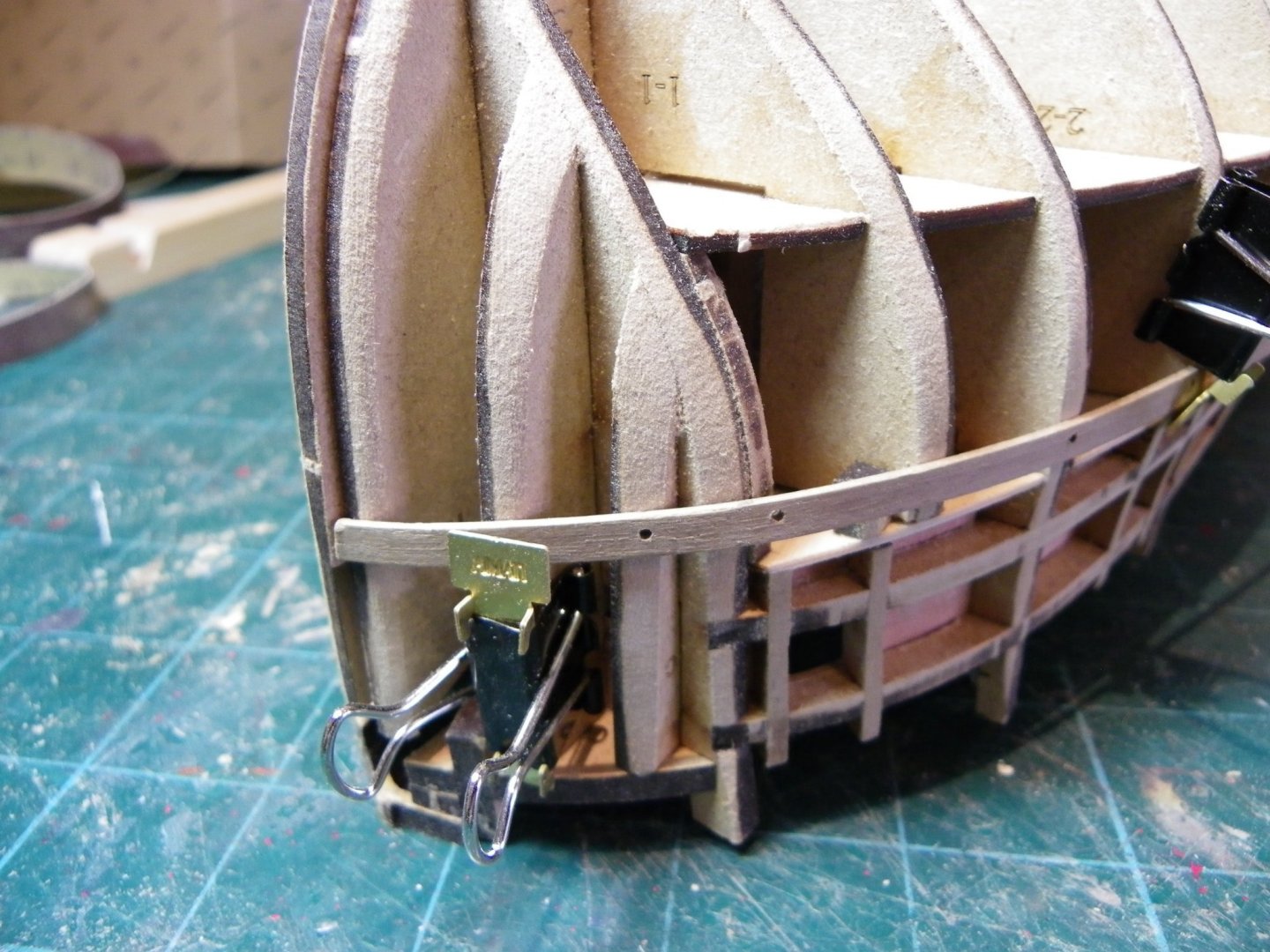
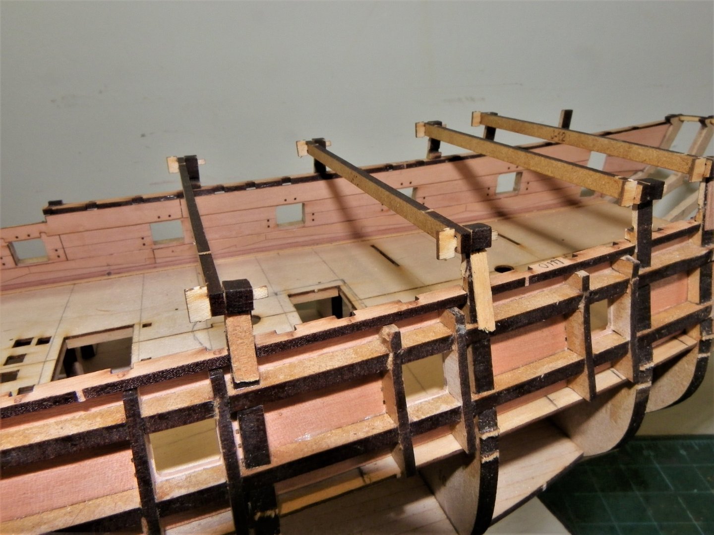
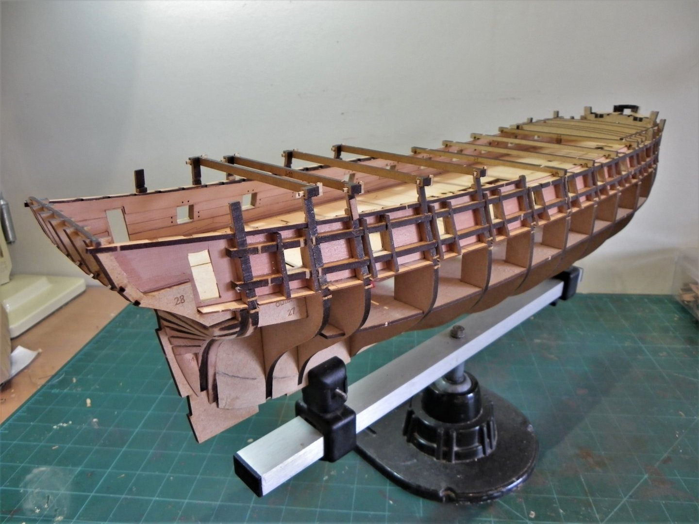
You're welcome Jacek.👍 A reconsideration. Back in Post 15 I expressed my doubts about the validity of the Quarterdeck area bulkhead extensions designed to hold bracing jigs to prevent spread of the hull. I had to splint four of them where they had broken off, seemingly by the simple act of looking at them.😉 0431 Oh, me of little faith, with the bracing jigs in place they have become quite firm and the splinting has held good. The splinting can be seen on two of the extensions. 0435 0432(2) 0429(2) 0433(2) In fact all the bracing jigs fitted perfectly across the hull, and I have to commend Chris on both the fit and the initial idea for this design feature. I'm still not entirely sure what difference the jigs will make, my hull feels pretty solid without any flex evident, but I will use the jigs as indicated. Movin' on. B.E. 24/09/21
.thumb.JPG.77c46bbe8d3a99adf4ee15fa9f9945d4.JPG)
.thumb.JPG.c677c753014b9e65b96473815f0c62d5.JPG)
.thumb.JPG.d9acecf6e2563f70e784c94911e22bc7.JPG)
- 857 replies
-
- 11
-
-
- Sphinx
- Vanguard Models
- (and 1 more)
-
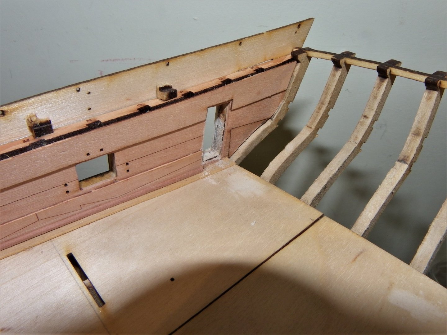
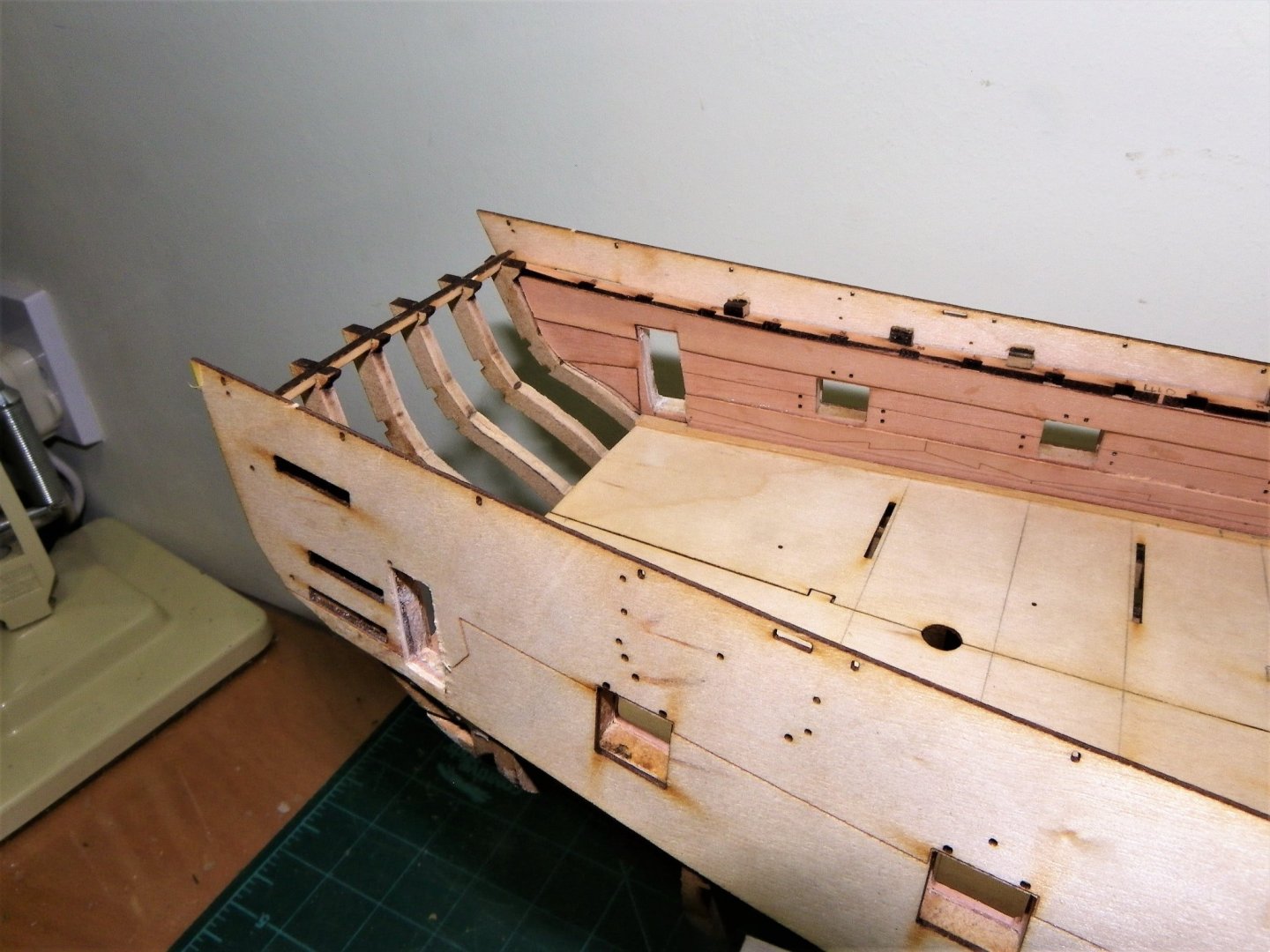
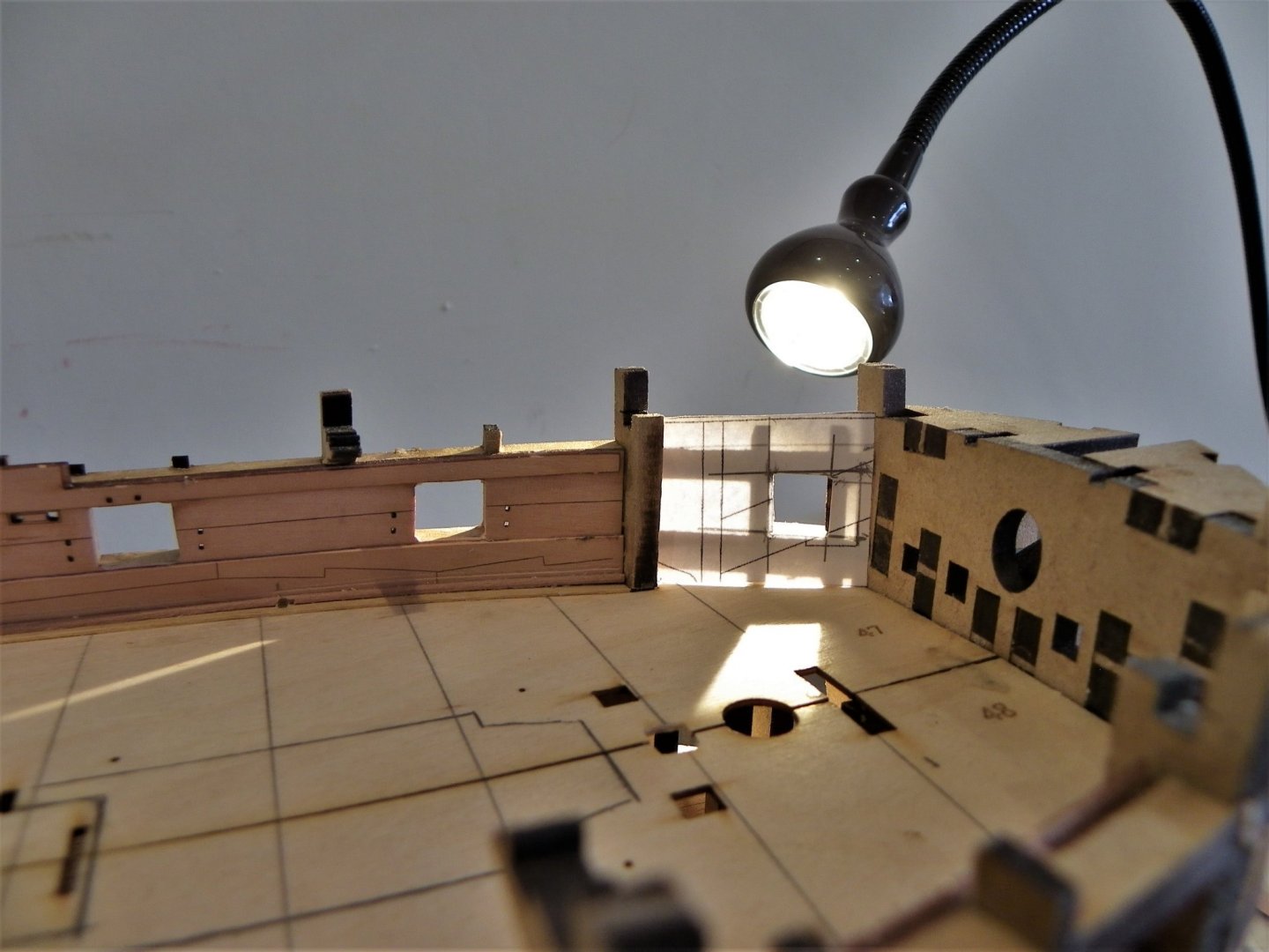
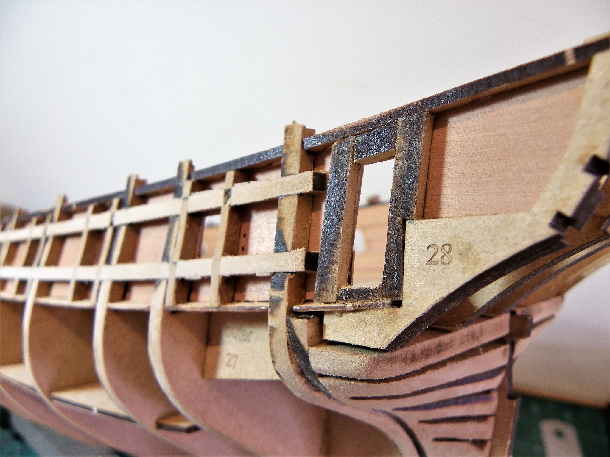
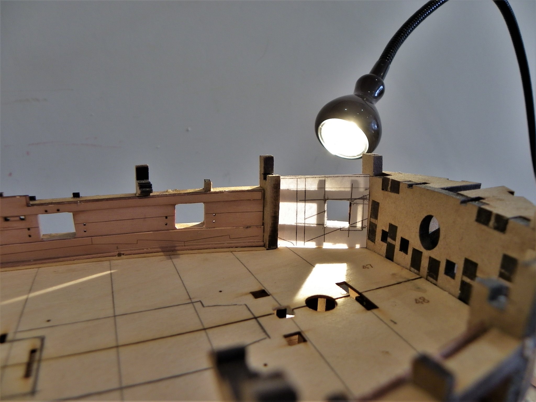
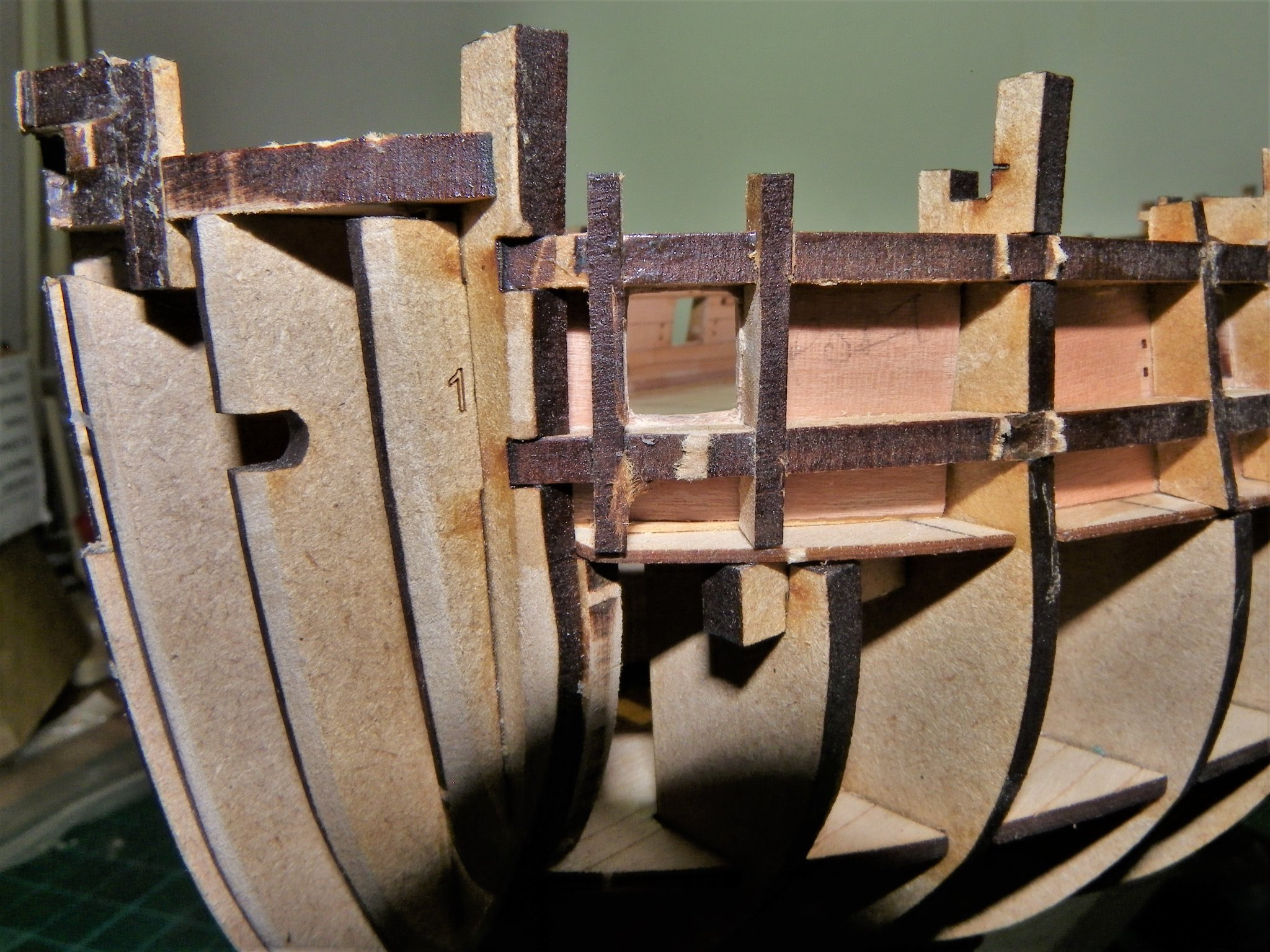
Post Nineteen Fitting out the Foc’sle A modest modification but one that cleans up the area around the bow. 0411 A paper pattern from the plan is used to mark out the area. 0420 Fairly straightforward, spare Pearwood from the bulwark and spirketting frets cut to fit. 0421 Frame 1-1 (with the notched extensions to take the carlings for the Fore deck) may yet be shaped to represent a knee below deck level. 0426 I am pleased to note that Chris has taken into account the difference in size of the Bridle port, something I failed to modify on my Pegasus build, and it still niggles. For the present that’s all that’s required for this modification. Before I add any paint to the model or add the upper deck planking it makes sense to me to get the outboard fairing done, so this will be the next task. Oh what joy. B.E. 24/09/21

- 857 replies
-
- 18
-
-
- Sphinx
- Vanguard Models
- (and 1 more)
-
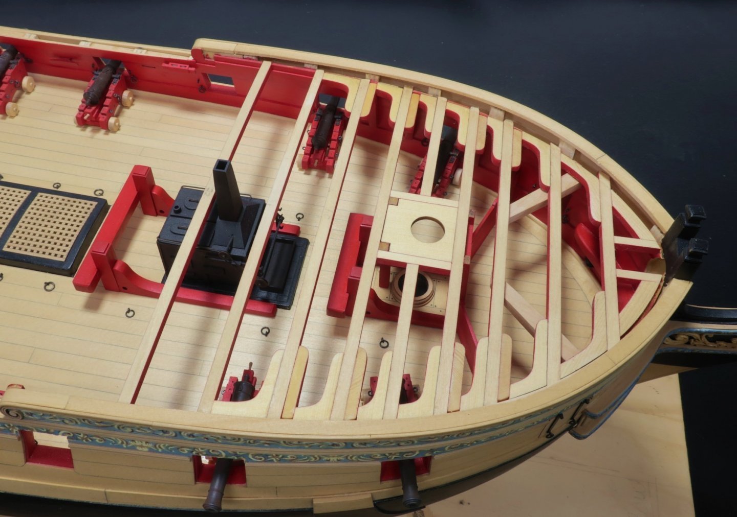
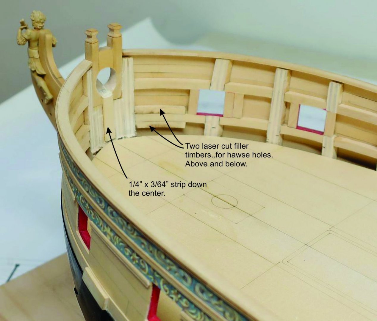
Thanks Glenn, The only reason I bought this kit was that Chris tempted me with great detail and the option to allow conversion to a Navy Board Style model, I have no real interest in a pure assembly job, pretty as the finished article is. I am following Chuck's Winchelsea build closely and it is of great help, gotta love that mans work. This is how the bow should be but even with the Sphinx kit limitations , a fair bit of it can be replicated. On this fabulous 'Winnie' shot it is all there to see. To his credit Chris has provided all the important stuff, and it is only the section equivalent to halfway past the first deck beam above, that is solid on the Sphinx. I'm happy to accept the kit limitations, and well placed Foc'sle decking will cover this. Regards, B.E.
- 857 replies
-
- 11
-
-
- Sphinx
- Vanguard Models
- (and 1 more)
-
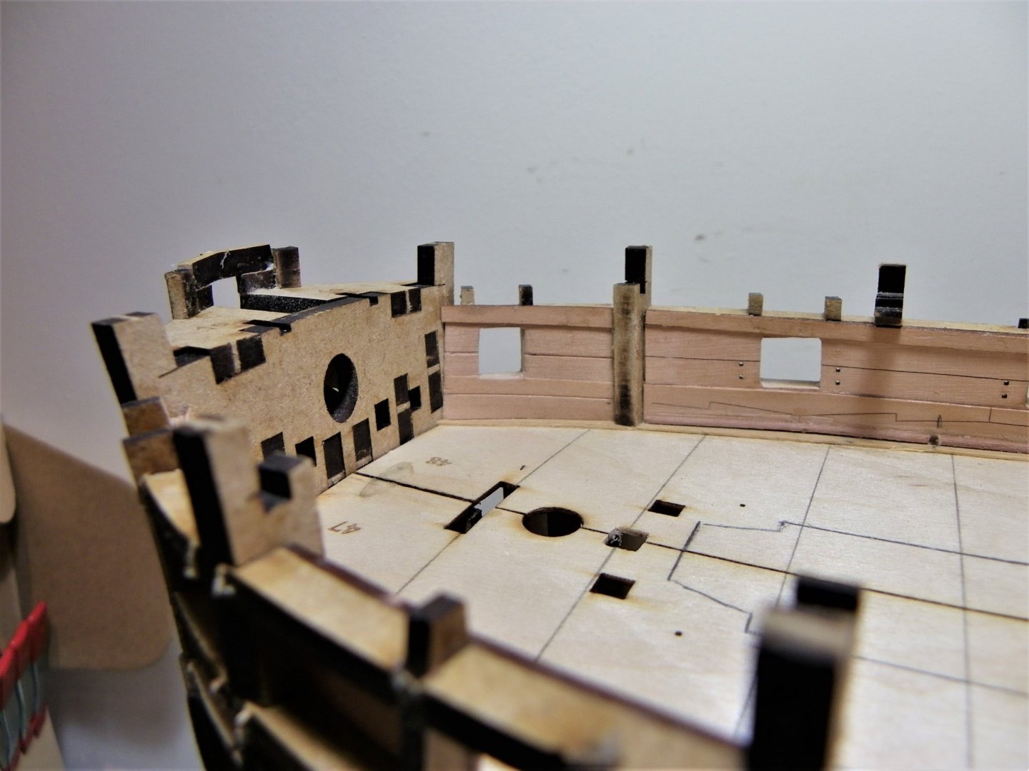
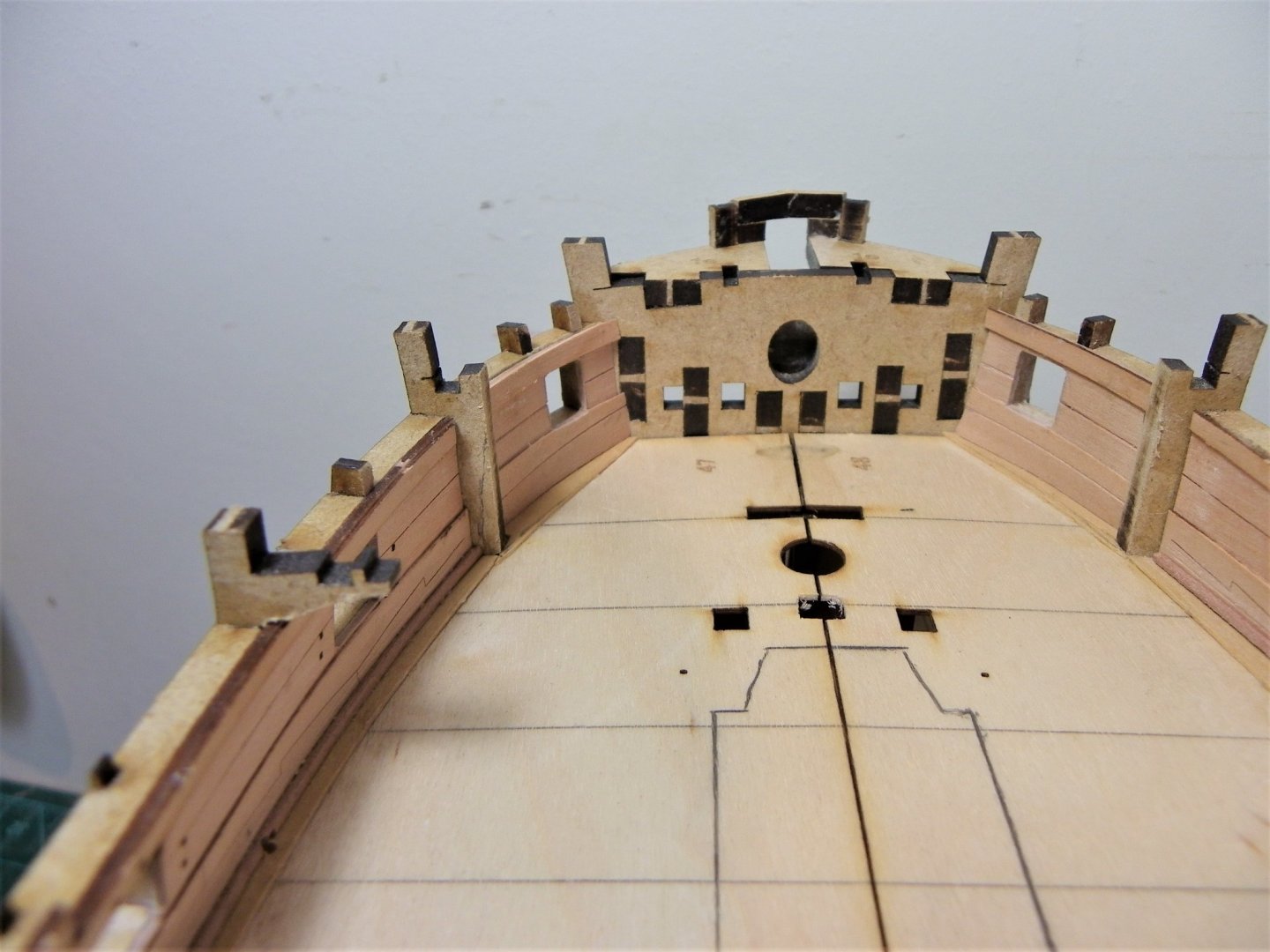
Post Eighteen Modifications, Modest and Middling. Waterways I fitted waterways and scuppers to Pegasus, so there’s no reason not to do so on the larger Sphinx. Rooting around my timber stock I found some 1mm Pearwood square stock, probably also supplied by Chris with one of his other kits. The tricky bit is chamfering an angled face on this tiny strip to take part of the scupper. I fitted the strip first and then used a micro chisel to cut the angle. 0400(2) Scuppers are 4”ø in the round, scaling to 1.5mm holes. The pre-cut scupper holes on the provided etched deck are around 1.2mm ø. 0402(1) The scupper is angled downward part thro’ the waterway and part on the Margin plank. That’s it for the present, I will need to represent the lead flanges at some time later in the build. What to do about the Bow space. As mine is a modification build my eyes are constantly being drawn to that area of the Upper deck below the Foc’sle. 0399 This is an unfinished area, no internal bulwark planking, unfaired frames, and an engraved closed bridle port lid on the outer planking pattern, which closes off any possible view of this area. What should be there is internal planking running to the stem and breast hooks with the hawse holes between. What is provided is the Bowsprit step, the Riding Bitts, and the Fore Jeer Bitts. Full modification is not possible because of the kit design but there is stuff that can be done that gives a more realistic impression. 0409(2) To get an idea I put into place those fittings in this area. Note: Stage 522/523 of the blurb covers the Fore Jeer Bitts(463) There is a note that the slot in the Gundeck on early batches of the kit needs easing to accept the shaft of the bitts which plugs into the lower deck. One of the arms of this ‘Y’ shaped piece broke along the grain line whilst trial fitting, Glued together using Aliphatic Resin glue, but it remains to be seen how strong the repaired piece will be. With the parts in place, I can see how to proceed. The bulwarks will be faired, planked and spirketted with the intention of leaving the Bridle ports open. Manger boards will be installed between the Bowsprit step and the forward side of the Bridle Port. The Foc’sle will be planked to the extent that the forward Bulkhead is covered and obscured from view. Better get on with it then. B.E. 23/09/21
.thumb.JPG.0a1d16fbaa703d5122014897552a4c38.JPG)
.thumb.JPG.51f2ae675f45061efb4fc2ce66c18655.JPG)
.thumb.JPG.7dee0cc859043a24130e7c138af1a410.JPG)
- 857 replies
-
- 15
-
-
- Sphinx
- Vanguard Models
- (and 1 more)
.JPG.d5e87c80bc94490a5ca0779fb96e7b0d.JPG)
.JPG.2d1f1cdde5bc40ab77747baecdc88e1d.JPG)
.JPG.773fb9fe517878a7cd3f605a7c483007.JPG)

.JPG.131d2ca3ffcfd8aa743211de1910fa7a.JPG)
.JPG.4bca3ae3a8512350790601c5665a8068.JPG)


.JPG.f12f67d77b11bacb4615783f398af138.JPG)
.JPG.a4cc68d6ba7a620f0ef26d2c7af82af5.JPG)
.JPG.9b21b9357d7a9153bfe256506252783d.JPG)
.JPG.181dee8e0b3fb641af330b096ee6448a.JPG)
.JPG.4c5f4bd141b06e29f464648559f4da08.JPG)
.JPG.23990bc839582f8240b6e21735bb91e5.JPG)
.JPG.bbb93bf18c5b4dc42da689f079ed1160.JPG)

.JPG.e7d8d8f25168a0f414bf39ba07012f9b.JPG)
.JPG.cf07741535354bf32a68ee80db07d9bd.JPG)
.JPG.3c1623e5a5ecada3bf4bf8c0140acc28.JPG)

.JPG.787ba62139a27e34e03e1055d69f8a6d.JPG)
.JPG.90ffebb1e9c8dc1343f15232c3c6a16d.JPG)
.JPG.d37d6a7030d9389a60b6b514b55afeed.JPG)
.JPG.1d820bc962ee19668730abc3d3272548.JPG)

.JPG.faf37b0c2be1f68ead19fca9c176ec53.JPG)
.JPG.c5fdd15102004b2324c7495876052324.JPG)
.JPG.f18aab519137467e4a2ba2a9a0a072de.JPG)


.JPG.dd22498d48a4b9682c6d917b94ff6d4d.JPG)


.JPG.9fd17fe8d869036e02d292c5886dfe7e.JPG)
.JPG.f968b21d870b30c0405dbe8f39dfdb75.JPG)
.jpg.249dab0c46ce98a18b401b34dd3ef989.jpg)
.JPG.8b47463883930e744429a2751926eb45.JPG)

.JPG.4c2f1282463bfb4f1bba341170df08b4.JPG)
.JPG.57feb6689f5761a1a5ea627fd2389e85.JPG)


.JPG.d0918e20052f26457334d8bf4e9f968c.JPG)
.JPG.95b5454e6c2f3c21830cd9e414b0fd9b.JPG)
.JPG.306bc7323bb8ce0642481ec2bdb24e6e.JPG)