
Marcus.K.
-
Posts
231 -
Joined
-
Last visited
Content Type
Profiles
Forums
Gallery
Events
Posts posted by Marcus.K.
-
-
Thanks Bob, for that very intersting insights.
Any idea about the year that New Bedford Flags Signal Flag "Poster" was done?
- thibaultron, mtaylor and Scottish Guy
-
 3
3
-
On 3/8/2024 at 3:25 AM, Roger Pellett said:
Of course, Constitution has had a very long life during which she has been rebuilt and repaired several times. For a considerable part of this time she sailed as an active unit of the US Navy so until recent times, her refits did not necessarily involve ensuring historical accuracy. Even today, she is a hodgepodge of different periods.
Constitution underwent a major repair in the 1920’s. There are photos of her during this repair in drydock with all exterior planking removed. Apparently, during this repair a series of as built drawings were prepared. In the 1990’s these drawings, on a DVD disc, were offered to the public. I believe that the drawing that you have posted is one from the 1920’s. To be useful to the level that you want you would have to be able to determine when different structural elements were added during which historic period.
Roger
You are absolutly right, Roger. And that´s part of the fun for me here. Its a bit like a "murder mistery" .. Cluedo in history. "who´s done it?" .. "who´s done what!?"
I am copying your remark to this thread - since I here think about the topic for my actual build.
We can only "guesstimate" about detail questions based on availble sources. The Lord drawings done in 1925-1930 are a reference for what they thought is right in that times. The section cut I showed here was prepared to show what his research result is indicating. But of course - it is also a lot of interpretation in that already. And as a matter of fact: he did his restoration based on modfied designs by the way - for which we also have section cuts.
I am about to re-think that thick stuff / king plank concept for my build. Until yesterday I intended to represent that step. But ..
There may be 2 reasons why Humphreys may not mention that "thick stuff":
1. he did not talk about it, since anyone would have known: this is how it had to be. That´s the tricky part with original sources: they often describe the "not-expected", the "unusal", the things worth to describe. Very often they don´t talk about things which are "common sense" / "common practice" for those in the time the paper was written. So "thick stuff" or "king planks" could have been a feature which every shipyard whould know how to do! Not worth talking about. As for example also the length or width of most of the deck planks.
2. he did not talk about it, since in his design it was not intended to be there.
That possiblity leaves us with two new options.
2a. there was no thick stuff in the early frigate
2b. there was thick stuff in the real ship: the shipyard did add in the best practical way - which is in a way the same as option 1. "common sense" / "common practice" - at least for them in Boston. .. Is there evidence for this? At least: I don´t have any.
Does anyone of you have evidence for the practice of "thick strakes" in Boston / Charlestown in that time period?
What do we have to consider than to find the best assumption here?
1. Humphreys degree of details in his specifications
Humphreys mentions the detail of width of his "thick strakes", the "sheer strake" beside the hatches - and also that there should be an additional one "half way" between this "classical" sheer strake and the sides.
He specified the type of wood (stronger white oak for areas with high stress and "cheaper" yellow pine everywhere else) he wants to have in different area of the deck.
He did NOT mention any "thick stuff" or "king plank" in between the hatches.
2. common practice?
It seems to me that the practice of thicker kingplank - or "thick stuff" as Lord is calling this - was not used in ALL ships ALL the time. Yes, it seems to be a practice in ship building before Old Ironsides was launched - and it seems to be practice up to today.
But there are ships and models (weaker arguement !!) without them.
In Chapmans "Architectural Navals" he shows ships WITH and WITHOUT a that step. If he does show in one drawing - why would he miss it in drawings of other ships? My conclusion: it must have been in some - and wasn´t in others.3. need to strengthen the ship
The argument it would strengthen the ship in longitundinal direction is not fully true - since the hatches interrupt that strengthening "stripe".
I would understand if that thick stuff is used in area the decks are under higher load during working on the hatches, storing stuff below the decks, You may have to put there a barrel or a box .. Those area around the hatches may even experience falling stuff.. So yes, in that sense thick planks would strengthen the deck.
4. personal bias
I loved that idea of having a deck planking which "differs" from what one ususally sees in forums like here. Of course I would love to show you all something new, never seen before but having good arguments to convince you all. I guess everyone posting information here does it, because it pleases to show to a community something entertaining or educational. It was a thrilling idea having here a detail, which wasn´t well understood before. But..
Thinking about all that without emotion and just rationally I would judge like
Pro:
- thicker king plank was a well known and appearing feature in some ships and models before and after
- thick stuff would improve the robustness of the "logistical" area around the hatches
- thick stuff is shown in John Lords "investigation"-section cut. Seems he saw some evidence for it.
Contra:
-
Humphreys tried to describe the important features he wanted to have
- he described the material to be used - and where.
- he described the thickness and in one occation (for deckplanking) the width of the material he wants to be used.
- he did no where describe "thick stuff" / king planks
- There is no evidence for "thick stuff" before the 1926 section cut drawing of John Lord.
- king plank as a feature is sometimes visible - but wasn´t exisiting in all vessels of that type
Summary
I guess I will not show white oak nor a step in between the hatches.. and deviate from John Lords 1926 interpretation.
Of course there may have been a step and white oak planks in the real ship from the beginning - but .. for today I guess I stick with what I read from Humphreys.
-
Just found in this great forum another hint for that "thick stuff" planks .. which - as it seems - are also known as King Plank.
-
Next question to think about:
Humphreys did specify the thickness of the deck planks .. I am right now on the gun deck:
Quote"Plank--Four inches thick, six feet from the side, of the best white oak, clear of all sap and other defects whatever, the rest e laid of the best heart pitch pine, clear of all sap and other defects whatever.
also the thick strakes are described like that:
QuoteThick strakes on the gun deck, two strakes of white oak plank six inches thick, and not less than ten inches wide, bolted and joggled into each other, and over and into the beams and leges two inches, running all fore and aft alsong side of the hatches
Two other strakes on each side, fite as above, midway between the water way and hatch stake.
John Lord did collect all that in one of his section cuts.

I did ask you already what you think about that step between the deck and the decks mid section - in between the hatches - in which the drawing indicates a thickness of 6".
That step would be
On 2/18/2024 at 1:03 PM, Marcus.K. said:.. making that step 2 1/2" thick. That´s more than 6 cm !
On Berth Deck this drawing shows also another dimension: it says " White Stuff 6" x 10" ". From optical point of view I would guess that this dimensions would also fit to the thick stuff on Gun Deck level.
That is interesting because: if you take the width of the hutches in the Waldo Deck Plan of 1819 and divide it by 7 planks as Lord seems to indicate here - then each planks width is 10.28". Bingo!
That would lead me to believe that those planks in between the hatches - and in between the two inner "thick strakes" (also of at least 10" width) had the same width - while the yellow pine planks - and maybe also the outer white oak planks below the guns (for a widht of 6 feet from the hull inwards) may have had a slightly smaller width.
The length now.. ?
Modern restorations seem to work with 40 feet long planks - as this paper indicates:
Materials on USS Constitution in 1992 - 1995 Restoration
But even older Material found on the USS Constitution Museums blog helps us:
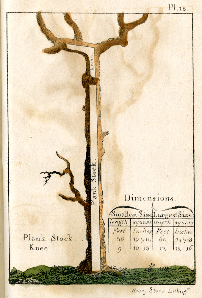
This paper from Peter Guillet’s Timber Merchant’s Guide. [USS Constitution Museum Collection, 1742.1] allows planks between 35 and up to 60 feet.
Thats between 10 and 18 m!
Since the end of the planks would need to be exactly on the center of a decks beam the span of 10 m would cover - depending on the position - about 6 to 7 deck beams. And with a bit more length even more beams can be covered with one plank - providing more stability.
Here a picture of how the Waldo Deck beams would be postitioned in our Revell hull:
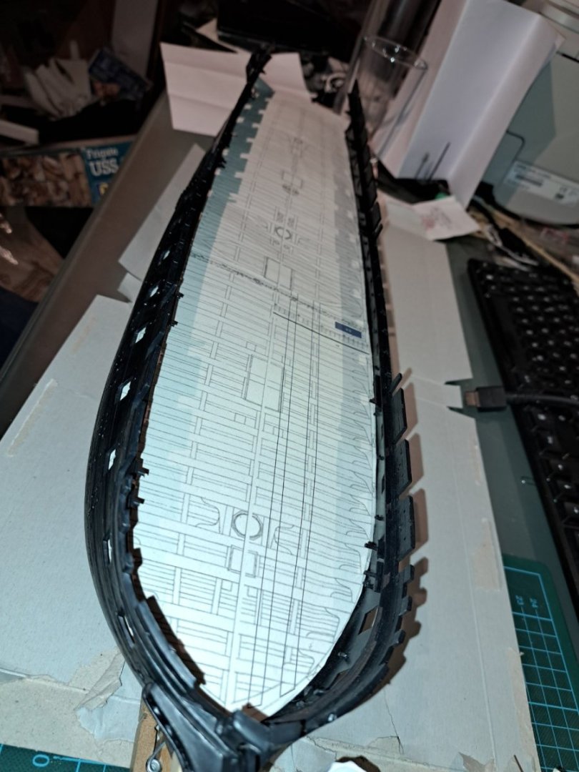
6 beams per plank - thats reminds me on this picture:
.jpg.e441bd31b706ce5e6bae4682232ff068.jpg)
Coming from HERE (thanks Gentlemen).
Of course that pattern will be possible only beside the hatches - since in the center of the deck there is always interuptions - like the hatches or the masts etc.
But in general I think I can work with about 10 - 15 m (in my case then 10 - 15 cm) long planks - and trying to match the deck beams by that pattern.
-
Today I have a question for you:
in the Humphreys Papers JH specified many of Old Ironsides items. I am interested in this one today:
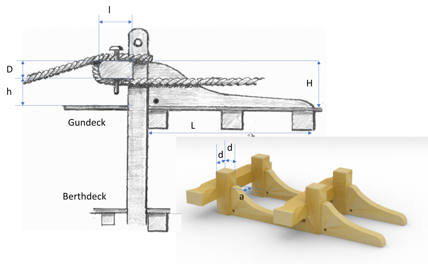
QuoteCable bitts
2 pair of good tough strong white oak 22 inch square and to taper below the lower deck beams to 16 inch crosspieces to be 22 inch fore and aft and 20 inch deep to have a standard knee against each bitt sided 14 inches to run forward over 3 beams and scored down over each 2 inches the arm to run to the upper side of the crosspiece
My interpretation
d = 22"
l = 22"
D = 16"
h = 20"
which makes
H = D + h
+ 2"- 2" ("scored down?") = 34"a = 14"

Do you think that is a correct interpretation?
How much would the crosspiece ends and the bitts "head" be wider than the distance of the beams / stand above the crosspiece??
Edit: I did change that height of the standard knew due to the statement says "scored DOWN" and since it would make sense that the knees "arm" is a bit lower than the upper edge of the crosspiece to provide a bit room for the cable wrapped around that bitts. But I admit: I do not really understand that last statement
Quote... and scored down over each 2 inches the arm to run to the upper side of the crosspiece
Am I right?
-
Ladies, Sirs, mates and pals,
I need your advice.
I just found something strange in John Lords Section Cut drawing 35208 where he is showing his research results from Humphrey-Papers concering Old Ironsides original layout. I guess it is to be viewed with a certain .. "sceptsism" since Lord did not have Internet or fellow forum colleauges to get advice from. And: it may be a drawing of a set of drawings- in which here missing information may be shown. What I for example noticed as missing information here: Lord refered to the demand of white oak planks 6 feet from the side for the Gun Deck - but did not advice the 5 feed white oak on upper deck - which Humphrey clearly did.
But my question for you experts: do you know any evindence for a raised mid section of the decks - in between the hatches - as Lord is showing here? This "white oak" which seem to run in between the hatches - and having a visible step vs. the white oak planks (interlocked?) "beside the hatches" ). It seems to be 6" while that "third straks" along the hatch seems to be described as 5 1/2" - but lowered into the beams.. and the yellow pine planks have a thickness of about 3 1/2" .. making that step 2 1/2" thick. That´s more than 6 cm !
I would think that stronger planks along the mid of a ships deck would help to increase stiffness in general - if there weren´t those hatches, which do "cut" the strengthening feature along the ships lengthwise axis. We know that Humphreys designed "interlocked thick strakes" .. and Lord shows them - one on Gun Deck and at least one in Berthdeck. There are white oak strakes along the hatches - which could be interlocked strakes too - but that is not shown explicitly in the drawing.
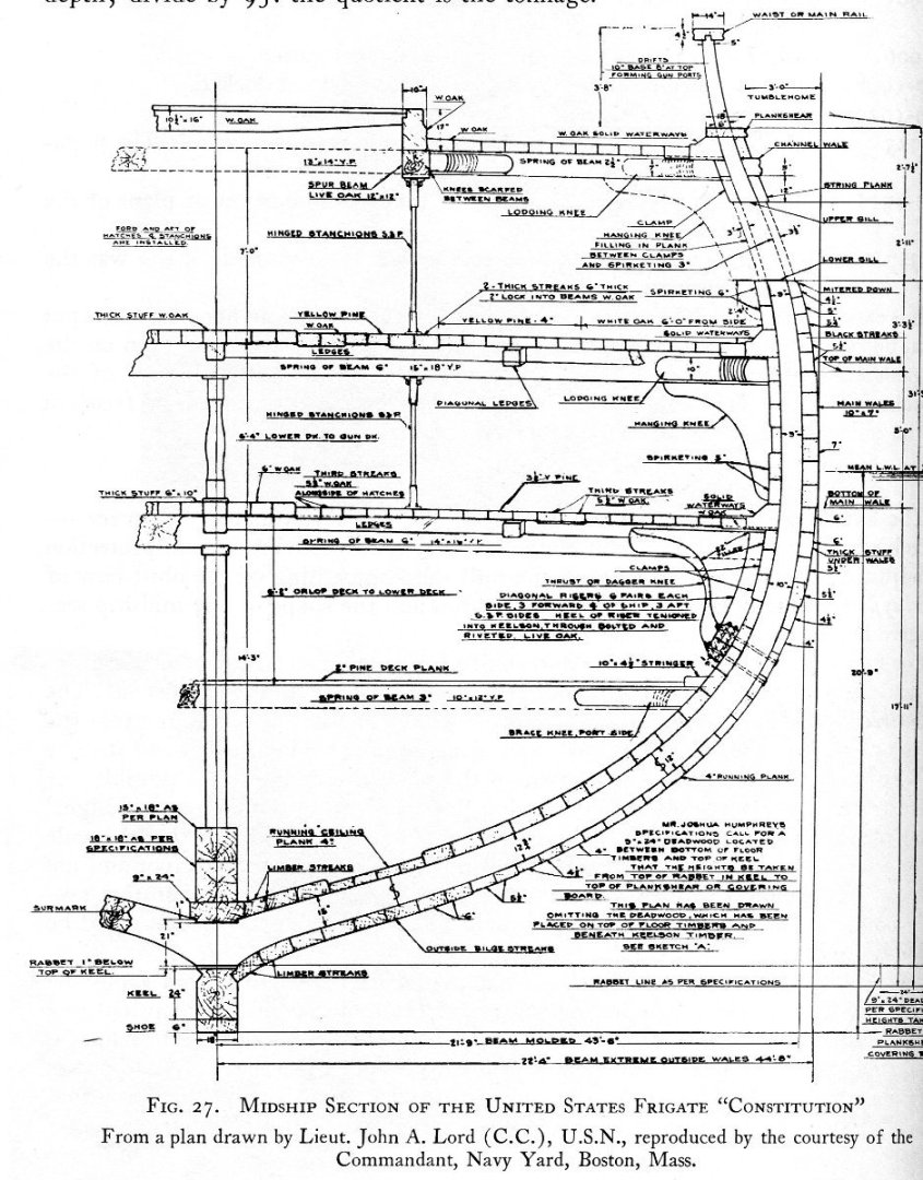
Source of this section cut: Alexander Mahoun´s "USS Constitution and other historic ships" - but also being part of John Lords 1926-31 restauration plans.
But again my main question: are there any other sources or evidence for a step on decks in that mid section - in the area of hatches? Isn´t that an obstacle for the crew - if you have to move a gun from one to the other side - if you have to run across the decks? Or is this just was Lord was thinking it should be?
What do you think?
And .. since you are looking: what does he show here in the center of the ship in Berth deck level: that "thick stuff" 6" ?? 10"? .. is this a 6" x 10"? What would that be? There is a dotted line - but what would that be??
- rybakov, allanyed, Keith Black and 1 other
-
4
-
Hmmmmm ... 🤔😉
Looking forward to your next one ... 🫡
-
9 hours ago, Thukydides said:
but all in all I feel it looks good enough for a first try.
Well yes, it does! And not really only for a first try!
Concerning the length of that breaching lines. They do look very long. But of course compared with what? Compared with our expectation coming from 100 and 1000 of pictures, fotos and illustrations in books, blogs, and more. Very rarely from real ships and never from a ship in real action. So is our expectation then realistic?
I would do the following: do a try on the model: look how far the gun would be able to run back without risking a collision with other deck features. Look for the most critical gun ... or do it for each pair, either to find a standard for the specific ship or assuming that each breaching was done individually for each gun (pair) to use the maximum space. We know that there are cases in which the gunners had to reach out of the hull, to work on the muzzles. But of course the more they managed to bring the muzzle inside, the more safe and - more important - the quicker they would reload the gun. So it is valid to expect, that the length was optimized to a maximum while still avoiding collision and damage. Keep room for the gun crew not to be squeezed in between two guns in the center of the deck 😉.
In any way: it looks phantastic!!
- mtbediz, Peanut6, jpalmer1970 and 2 others
-
5
-
"Computers are made to help us in problems we would not have without them!"
I hate to be forced to change my way of working (which was really on very professionell level with the "non-cloud" office) every time MS is reworking their product. What they call "intuitive" is a nightmare for me, since my "intuition" forces me to follow the way I had learned before... Why can't they offer an option like "all functions and menues as in previously used configuration". Well, they don't do that... even if they could...
Good luck with the new cloud based version...
-
I was again looking into this.
The "thing" in the left field may be a "Celtic Harp" instead of a shield as the harp was used in heraldic systems for example in british and in celtic symbols. Behind it, left side, there may be visible the bow of a crossbow?
On the right field there seem to be the end piece of a brass instrument behind that shield, right?
In the center field I think it is either a shield (backside and not upright but 90° rotated to the left) behind that helmet? The top side of the shield (now left side) seems clear to me, but the bottom side (here right of that helmet) seem to be rounded, not with a tip. We look into the backside of the shield, therefore the plain yellow and just shadows indicating the hollow shape of that shield. That grey "bow" left of the helmets sholderpiece may be one of the shields handles. There seem to be more weapons or floral twigs or sprigs behind and around the arrangement. And yes: a lance behind and crossing diagonal.. .
Right field: maybe that huge tip in the round shield is'nt meant to be that big. I think it's outer end color matches with the more greenish weapons behind the yellowish shield. Maybe what looks like the outmost tip is in fact one end of a club or other weapon or instrument and they are just accidently that close?
Or: since that brass instruments bell matches that color of what we believieved to see as a round shield.. it is in fact a french horn or a tuba.. and something Stick through its center.. or is the mouth piece??
But this thing is really hard to interpret!!
Anyway: fun! And interesting if you start digging in those symbolic elements... I learned about helmets, heraldic, harps...
- Thukydides, jpalmer1970 and Mr Whippy
-
2
-
 1
1
-
I would guess that all three fields show a certain shield and behind different weapons. The left one being a shield as knights would have used. Classical heraldic shape, not symetrical and with that cutout for the knights left leg on his horse (strange - he must be lefthanded??) . The right one being a round somehow ottoman shield (?) with a sharp tip in its center.. The center one is strange in its shape.. but would be reasonable if my interpretation of the surrounding weapons is right. But it is guessing...
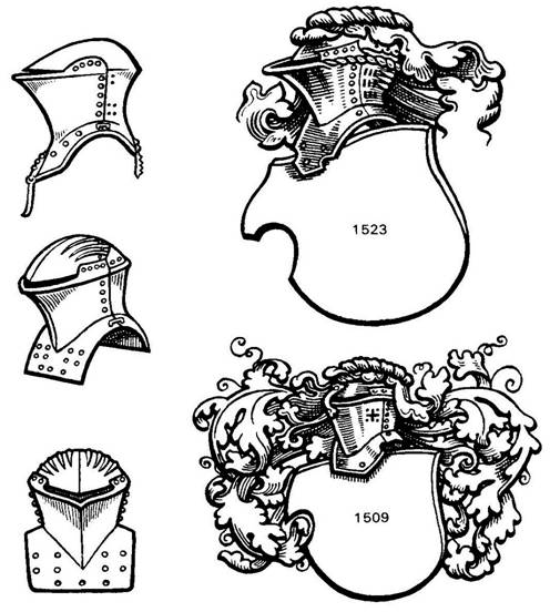
No!! .. the center one is a knights "tilting helmet" with bushes on top in front of a huge shield or a coat in front of weapons!! I will check for good pictures for what I believe to see...
Here a picture for a tilting helmet ...
http://bridges.rem33.com/books/vonValborth_A2a_files/image020.jpg
Its the left side middle one I think I can see in the center one of Alerts paintings..
Found it here:
- Thukydides, jpalmer1970 and Gregory
-
3
-
- Force9 and Mirabell61
-
2
-
Gentlemen,
no matter WHEN that "welcome matt" may have been added: I believe, you see it litterally from the wrong side 😁.
Imagine the Admiral wants to leave and that spot in front of that opening is wet due to the opening.. wet and slippery! Imagine he would slip and falls down? "Man over Board!" 's the call!!
So better to have the chance for wind and air to dry this spot where he places his foot onto (that grating) while water may be on the deck in front of the waterway... He would not slip on that ... his shoes would step on something more dry with more grib..
Its not an entry port grate, it is an EXIT port grate.🤣
-
Hello Stuart,
your stove is perfect! I just recently found drawings of those brodie stoves - and you did a really good job.
And your windows in the stern are the very best adaption I ever saw on that Revel-model. Was thinking about doing a comparable approach - but I wanted first to do some "replicas" with a silicon mold (first attempts were not really successful) since I would like to rework the decoratoin too ... I do not dare to do that with the only part I have right now. I was thinking about widening to upper or the lower end of the windows - but your result (doing on both sides) generates a very pleasing appearance! It fits perfect that way!
I think the Revel stern is an excellent representation of the 1812 appearance - as many others I just doubt that 4-patterend windows in the Hull-Model. But since they seem to be done in a comparable poor quality - and even in a strange way "added" into that stern, I tend to believe they have not been done by the same person doing so many things with so much care. Compare to the gallery windows .. So I guess that 4-pane-windows have been a "compromise" - as Olof Eriksen is interpreting: maybe done in a hurry before Hull left the ship and crew.. By the way: the Hull model stern windows are not squared as the Smithonian- and the Revell-model ones ..
What you did here with those windows is an excellent adaption of the Corné paintings and as I think - the most likely appearance of 1812.
VERY COOL - Looking forward to see it colored.
Hope you are doing fine and looking forward seeing more inspirational results from your beautiful build.
-
I agree: its a Revell kit. Nice to see that again. I did even forget I once did build it.. oh how long ago! Where has it gone by now? Thanks for the reminder!
- thibaultron, mtaylor and Canute
-
3
-
Hello Wefalck,
this tiny work is fascinating! I can not imagine how you can do things like that!
A proposal for the foots plates of those stanchions which you wished to be not that prominent: I noticed on the real ship´s photo: for me it seems, the foot itself was painted in the colour of the deck - dark gray. If you´d do the same, you would take away the "optical weight" of those foots. But maybe you do a test on a sample first - because it looks already so excellent.. and I would not dare to try to optimize and then mess it up!
Wonderful work!!
- mbp521, FriedClams, mtaylor and 2 others
-
5
-
That´s a very interesting build ! I am looking forward seeing more 🙂 ! I very much like your carpet - and the deck beams look very cool. To move the gunports is daring - your approach very interesting. I need to dig into that. Would the gun ports have been moved? Humphrey specified their position as far as I remember in his layout 1794.. Did you compare with Humphrey-Doughty Plan? I will investigate in that too.
Looking forward in further progress 🙂 Happy Eastern to everyone!
-
I know THAT experience! 🤣
- mtaylor, Canute and Keith Black
-
 3
3
-
On 2/23/2013 at 8:30 PM, Force9 said:
....
I would think, however, that shot storage around the hatches would be a standard approach in 1812. Certainly many period models would show these included. But is there more justification?
Here is my reasoning... Old Ironsides pounded HMS Guerriere to kindling in only 30 minutes. Evidence very strongly suggests that part of the reason was that the American gun crews fired TWO round shot on EVERY discharge during the battle. The data suggests that each gun shot @10 times in 30 minutes. That is a lot of cannon balls to have to haul up the companionways. Common sense would suggest that the crew pre-positioned most of that in shot racks before the shooting began - and they'd need plenty of storage. I suspect that there was storage around the hatches AND in between each gun - at least on the main gun deck. This would seem to be supported by the c1820 gun deck plan of USS United States made by Charles Ware which shows both storage options in place:
...
Thanks for enduring a brain dump.
I love to read frequently your posts, @Force9 .. what´s your beauty doing?
And even more important: how are you doing? Hope all sails are up and flying??
Concerning your conclusion from data: "The data suggests that each gun shot @10 times in 30 minutes. "
wouldn´t in a single ship combat the 10 shot´s per gun and 30 min. mean that they shot in fact 20 times per 30 min?.. or maybe double shots for short range maximized damage? ..
... since there would not be any sense in using both sides the same time - but sequentially?
-
On 2/23/2013 at 8:30 PM, Force9 said:
....
I would think, however, that shot storage around the hatches would be a standard approach in 1812. Certainly many period models would show these included. But is there more justification?
Here is my reasoning... Old Ironsides pounded HMS Guerriere to kindling in only 30 minutes. Evidence very strongly suggests that part of the reason was that the American gun crews fired TWO round shot on EVERY discharge during the battle. The data suggests that each gun shot @10 times in 30 minutes. That is a lot of cannon balls to have to haul up the companionways. Common sense would suggest that the crew pre-positioned most of that in shot racks before the shooting began - and they'd need plenty of storage. I suspect that there was storage around the hatches AND in between each gun - at least on the main gun deck. This would seem to be supported by the c1820 gun deck plan of USS United States made by Charles Ware which shows both storage options in place:
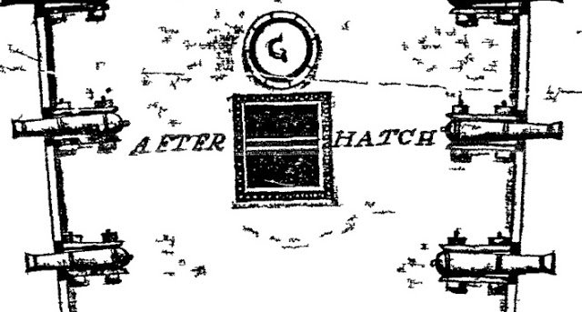
Using this deck plan as guidance, I intend to include shot racks in between the 24 pdr guns on my model in addition to what you already see around the hatches.
The spar deck is another matter... I will include shot storage around the hatches on that deck as well, but NOT include shot racks between the carronades. Despite the guidance from the Bluejacket manual and other representations (Gilkerson’s painting in the Gillmer “Old Ironsides...” book), I just don’t think that was a practical solution. Many of those guns have pin rails in between them and the necessary cordage dangling down would likely be in the way... The same deck plans of USS United States offer a solution. Here is the spar deck:
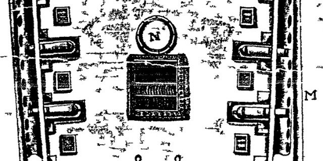
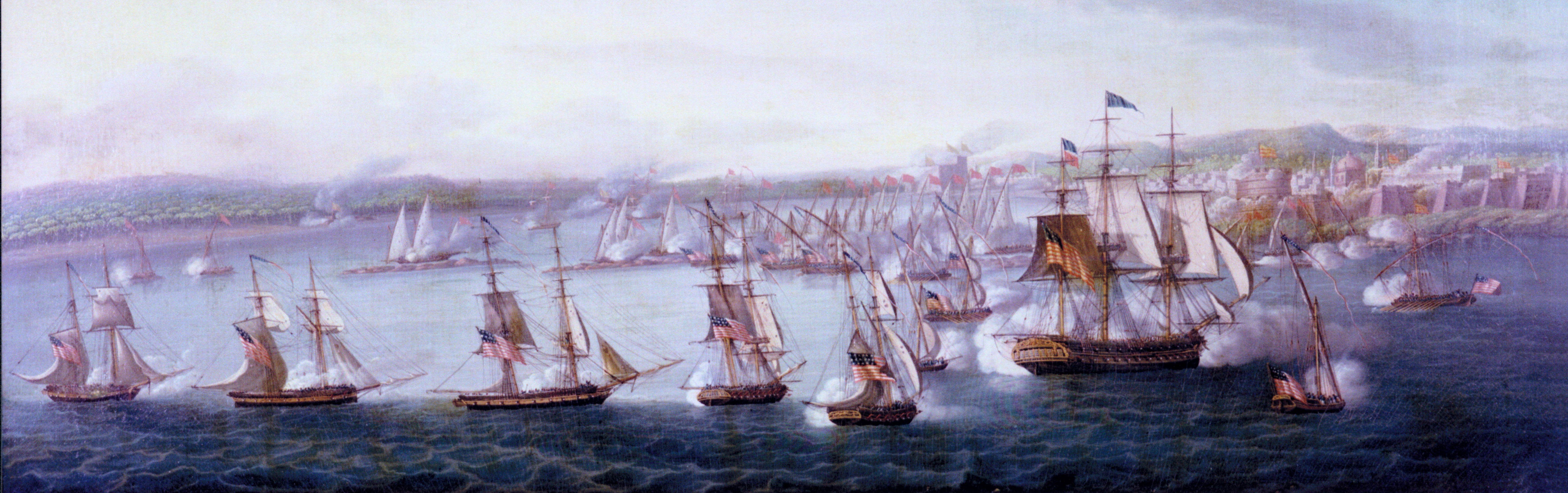
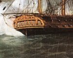
This clearly shows that the carronades would have a tray of round shot close at hand for battle as well as shot stored around the hatches. There is also another clue that helps me justify my approach. If you were a famous personage back in that era, the most flattering compliment would be to have your portrait painted by an accomplished artist. This was a very expensive thing to do back in those days - often many thousands of dollars in an age when a good sailor made 10 bucks a month. The important businessmen in the City of New York commonly took up a subscription to pay for a commissioned work of military heroes after a great victory. They gradually built up a significant "Hall of Fame" collection in city hall. Here is the one done for Commodore William Bainbridge following his victory over HMS Java (still in the collection of the city of New York http://www.nyc.gov/html/artcom/html/portrait/portrait.shtml😞
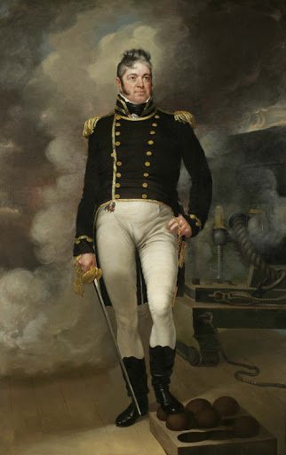
We see the talented artist captured the Commodore’s famous arrogance and pomposity. He has also captured something else - look at the shot tray under Bainbridge’s boot. This is the approach I’ll take for the spar deck. (We’ll come back to this painting when it comes time for the carronades).
I don’t mean to overly sway everyone in my direction. Unlike Cdr Tyrone Martin and others, I’m not an historian or professional researcher... Folks have to go with what works for them and this approach just feels right to me.
Thanks for enduring a brain dump.
I love to read frequently your posts, @Force9 .. what´s your beauty doing?
And even more important: how are you doing? Hope all sails are up and flying??
Concerning your conclusion from data: "The data suggests that each gun shot @10 times in 30 minutes. "
wouldn´t in a single ship combat the 10 shot´s per gun and 30 min. mean that they shot in fact 20 times per 30 min?.. or maybe double shots for short range maximized damage? ..
... since there would not be any sense in using both sides the same time - but sequentially?
-
On 2/23/2013 at 8:30 PM, Force9 said:
....
I would think, however, that shot storage around the hatches would be a standard approach in 1812. Certainly many period models would show these included. But is there more justification?
Here is my reasoning... Old Ironsides pounded HMS Guerriere to kindling in only 30 minutes. Evidence very strongly suggests that part of the reason was that the American gun crews fired TWO round shot on EVERY discharge during the battle. The data suggests that each gun shot @10 times in 30 minutes. That is a lot of cannon balls to have to haul up the companionways. Common sense would suggest that the crew pre-positioned most of that in shot racks before the shooting began - and they'd need plenty of storage. I suspect that there was storage around the hatches AND in between each gun - at least on the main gun deck. This would seem to be supported by the c1820 gun deck plan of USS United States made by Charles Ware which shows both storage options in place:
Using this deck plan as guidance, I intend to include shot racks in between the 24 pdr guns on my model in addition to what you already see around the hatches.
The spar deck is another matter... I will include shot storage around the hatches on that deck as well, but NOT include shot racks between the carronades. Despite the guidance from the Bluejacket manual and other representations (Gilkerson’s painting in the Gillmer “Old Ironsides...” book), I just don’t think that was a practical solution. Many of those guns have pin rails in between them and the necessary cordage dangling down would likely be in the way... The same deck plans of USS United States offer a solution. Here is the spar deck:
This clearly shows that the carronades would have a tray of round shot close at hand for battle as well as shot stored around the hatches. There is also another clue that helps me justify my approach. If you were a famous personage back in that era, the most flattering compliment would be to have your portrait painted by an accomplished artist. This was a very expensive thing to do back in those days - often many thousands of dollars in an age when a good sailor made 10 bucks a month. The important businessmen in the City of New York commonly took up a subscription to pay for a commissioned work of military heroes after a great victory. They gradually built up a significant "Hall of Fame" collection in city hall. Here is the one done for Commodore William Bainbridge following his victory over HMS Java (still in the collection of the city of New York http://www.nyc.gov/html/artcom/html/portrait/portrait.shtml😞
We see the talented artist captured the Commodore’s famous arrogance and pomposity. He has also captured something else - look at the shot tray under Bainbridge’s boot. This is the approach I’ll take for the spar deck. (We’ll come back to this painting when it comes time for the carronades).
I don’t mean to overly sway everyone in my direction. Unlike Cdr Tyrone Martin and others, I’m not an historian or professional researcher... Folks have to go with what works for them and this approach just feels right to me.
Thanks for enduring a brain dump.
I love to read frequently your posts, @Force9 .. what´s your beauty doing?
And even more important: how are you doing? Hope all sails are up and flying??
Concerning your conclusion from data: "The data suggests that each gun shot @10 times in 30 minutes. "
wouldn´t in a single ship combat the 10 shot´s per gun and 30 min. mean that they shot in fact 20 times per 30 min?.. or maybe double shots for short range maximized damage? ..
... since there would not be any sense in using both sides the same time - but sequentially?

Flag with ship name reversed on one side?
in Masting, rigging and sails
Posted
Question is raised via e-mail... I´ll let you know whenever I get an answer!
I marked the most important statement 😀 - and whenever I will be in New England: this for sure is one of the oh-so-many places I will visit!