
Chuck Seiler
-
Posts
1,878 -
Joined
-
Last visited
Content Type
Profiles
Forums
Gallery
Events
Everything posted by Chuck Seiler
-

Is there an easy wooden tall ship out there to build?
Chuck Seiler replied to thegrindre's topic in Wood ship model kits
'Don't fry bacon in the nude' NOW you tell me. I would NOT recommend either the Model Expo 18th Century Longboat or a card model-particularly the paper ones. I have built both (all 3?). The longboat is a great model. Looks simple but really is not, considering planking needs to be PERFECT since you see both sides of it (inside and out). There are many great card models out there as well except I find the smaller parts deform when removing from the sheet. Alos I find it harder to work with than wood. Stay away from paper at this point. If you have a level of dexterity above me, you might want to try the SHIPYARD model of the ALERT. Nina and Pinta are good choices in that they are relatively simple. You also have an option with Nina in that you can build it as it was before Columbus got to the Canary Islands or after...he had the rig changed to better handle the expected wind conditions...but that may be a project too far. As Bob Cleek said, we really don't know exactly what they looked like, only close approximation. At this point in your model building career, that is probably not an issue. Monetary cost is only one measure of cost. Some models are very poor quality and some have really poor instructions. A slightly more expensive kit may be a better choice if it enhances your building experience. Poor instructions can be overcome by the many fine build logs here. Poor material can only be remedied by scratch building/bashing. Expect to make mistakes. Most people do first time around. I still am 20 years later. Get a bottle of alcohol (2, actually...1 bottle of rubbing alcohol and 1 of scotch). Use the rubbing to de-glue your gluing errors. Fix the problems...don't try and paper over them The just compound. Enjoy the experience! -
Yeah, not anymore. In all cases I needed to cut down the bottom of the extensions. The first couple I didn't, so they extend(ed) way high. Even when cutting down, many of the extensions were too high and needed to be trimmed. I already know that the top and bottom notches are too small and that the overall length of the extensions are probably too short to accept all three inner strakes. I have been thinking about how I will handle that. Definitely bend to fit, paint to match.
- 130 replies
-
- 3
-

-
- wütender hund
- hanseatic
- (and 2 more)
-
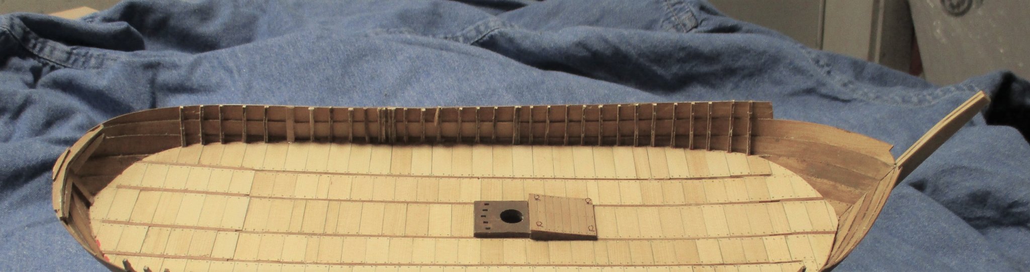
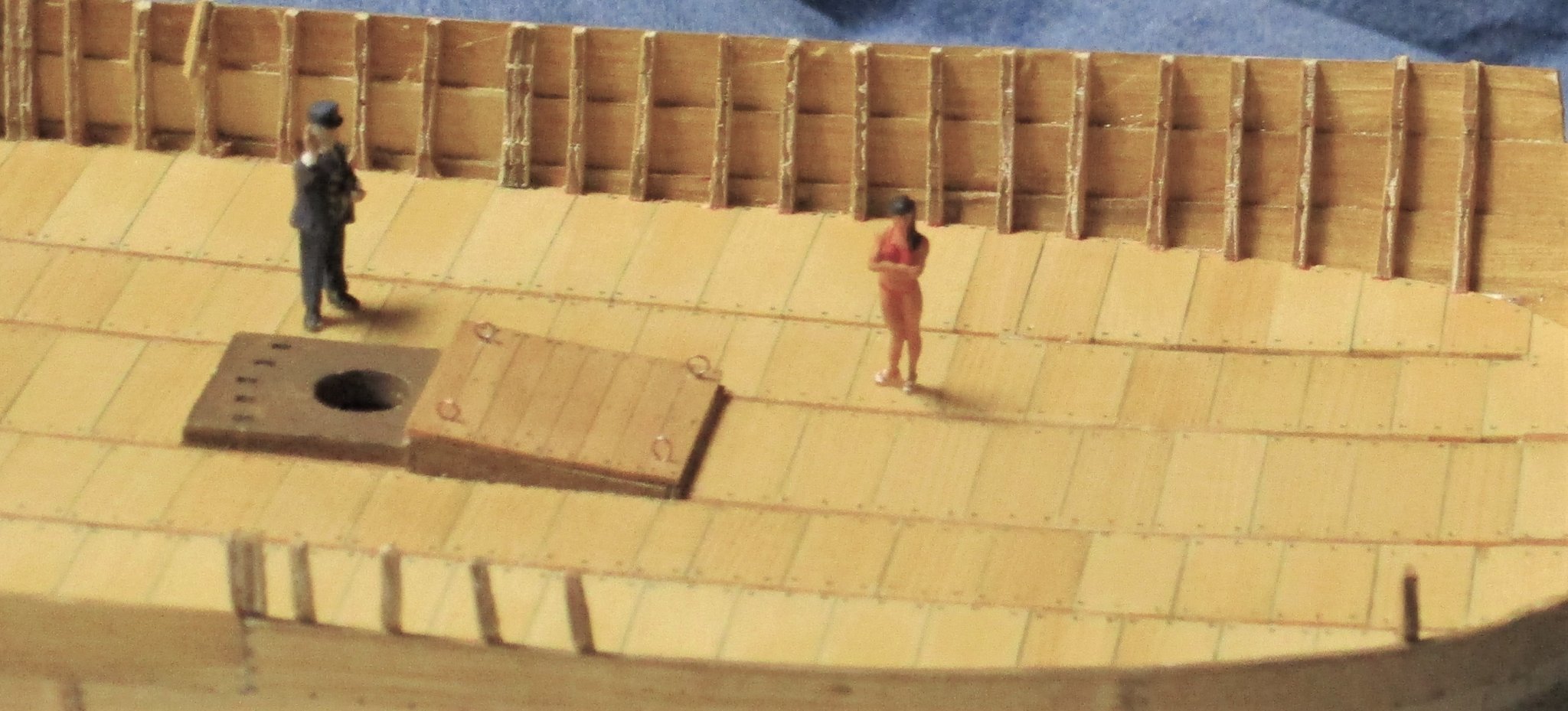
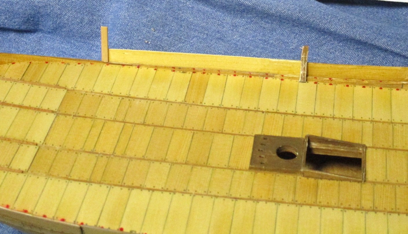
Progress continues. I have completed the frame extensions on the port side and added the top exterior plank strake. I am really having problems with the frame extensions. I primed and painted them while attached to the card, as the instructions recommended for the planking. While this prevents curling (if painted after removal) it leaves residue on surfaces I don't want residue on. Some of them were difficult to remove. It almost felt that they had been exposed to humidity and were kind of mushy. Southern California is not known for high humidity, but this is a strange summer. These are also frail beasties subject to breakage. Each time I would pick it up ( normally with visors...thus creating focal strangeness) I would have the chance of bumping into a frame. As you can see. Many were bent. A closer look at the frames. The yard supervisor greets a visiting tourist. I was told there would be a pool. Chris' ship has a pool. No ma'am, no pool. Chris' pool was planked over. Dang! Hey, you are not including me in your build log just to attract viewers are you. No ma'am. That would be ungentlemanly and I would not like to be accused of that. Besides, I have a job for you...as lookout. Everybody will be looking at you in the fighting top and ignoring the crappy hull planking. A look at the planking from the exterior as well as a closer look at the cargo hatch now in place. (Could be a pool cover). I added eye bolts to the hatch. In an effort to avoid SOME damage, I installed part of the starboard side top strake before continuing with the frame extensions.


- 130 replies
-
- 6
-
-
- wütender hund
- hanseatic
- (and 2 more)
-
I am at that point now. I was watching out for this, but found a different problem. There is a part (135) in thicker cardboard, then there is a better quality but thinner overlay (135a). So for each you have 135L, 135aL, 135p and 135ap. In my case, some of the overlays are reversed so that 135aL covers 135P. As long as you are paying attention, it is not an issue. Great work so far Chris!!!
- 179 replies
-
- 2
-
-
- shipyard
- wütender hund
- (and 1 more)
-
Degluing
Chuck Seiler replied to Zooker's topic in Building, Framing, Planking and plating a ships hull and deck
I guess that would be dependent on the situation. If it was old fashioned hobby model building, probably water based. Epoxy and other resin glues were available, but I suspect were not used much by modelers. If you are looking at other applications, that may be different. -
As I mentioned in my log, pretty clunky looking but it did the job. It didn't have to far or fast but it did have to haul the goods. Later, when speed became more important, the length to beam ratios changed.
- 179 replies
-
- 2
-
-
- shipyard
- wütender hund
- (and 1 more)
-
The thing up forward? I have seen it described as an above deck, athwartship deck beam...as opposed to the 4 or 5 that are below deck. They all end up sticking out the sides like an old adobe house in Santa Fe, New Mexico. Fore warned is fore armed. I am about a week away from that.
- 179 replies
-
- 2
-
-
- shipyard
- wütender hund
- (and 1 more)
-
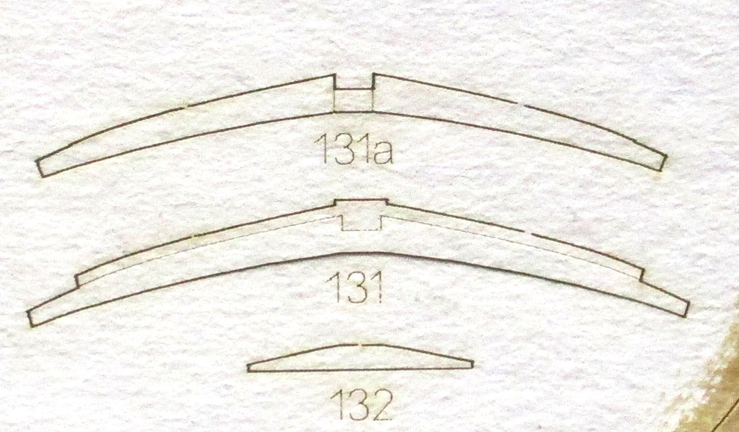
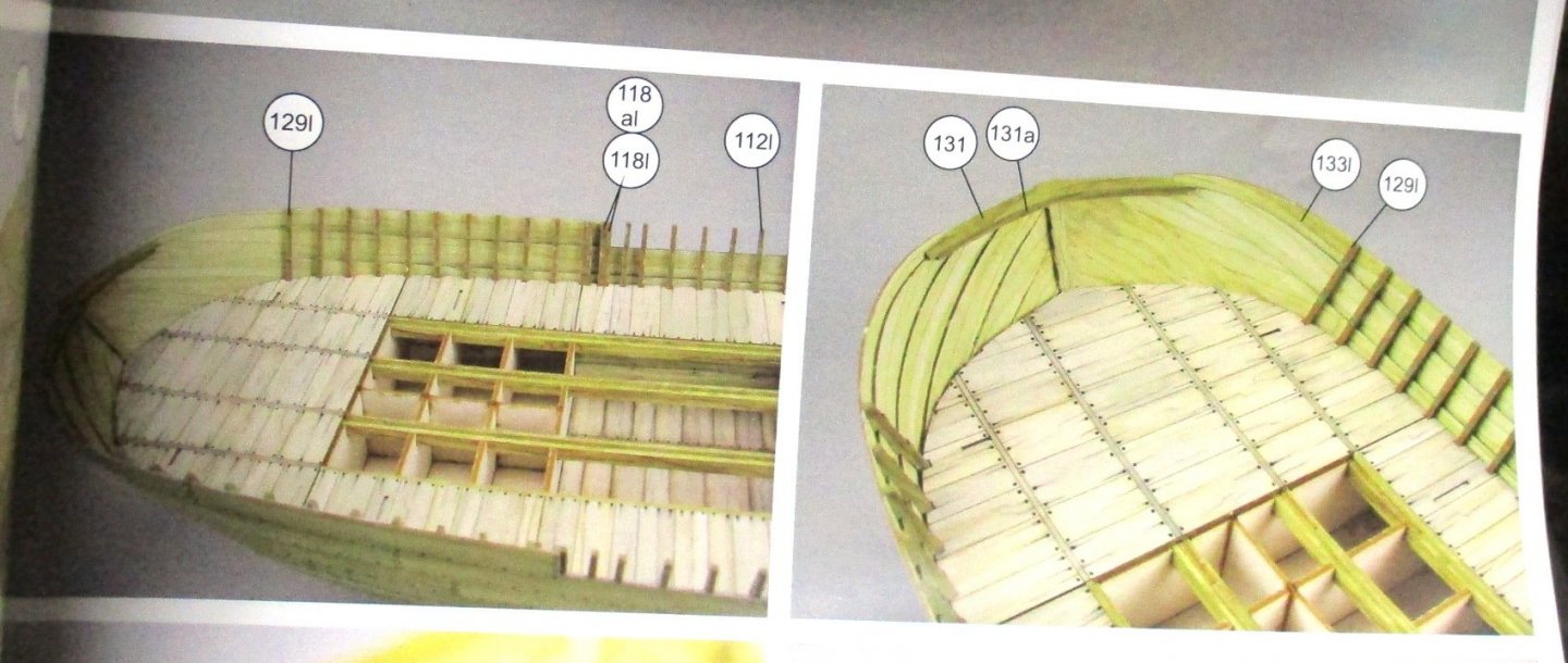
Originally a question...now a cautionary tale. As I am almost finished hull planking, I come to a part where I make a caprail sort of structure for the stern. The sheet has parts 131, 131a and 132. ...however the instructions only tell me about 131 and 131a. I scoured the instructions and saw nothing on this. I THINK I know what it is for, but I don't want to do anything the instructions don't tell me (as if THAT has ever happened before). My question was going to be...what is this for? As I was pondering this, Chris posted some shots of his progress. Huzzah!!!! There it is!!!!! Question answered, but another example of SHIPYARD instructions being incomplete.


- 130 replies
-
- 7
-
-
- wütender hund
- hanseatic
- (and 2 more)
-
Acronyms- They are the spice of life. ALLRIGHTY!!!!! We got to page 2!!!!
- 130 replies
-
- 1
-
-
- wütender hund
- hanseatic
- (and 2 more)
-
While the two SHIPYARD models above are not the definitive authority on cogs, I believe they do faithfully represent two styles of cog as seen in many of the paintings, coins and tapestries you have posted. I would also like to throw in-various replicas. While one style has NO fore-castle, another has a very clear forward castle integrally built into the ship. WH appears to represent the middle ground where you can take your basic commercial cog, run down to Home Depot and get some lumber, slap together a forecastle and duct tape it to the bodacious stempiece. Obviously the various depictions span several centuries and can be attributed to different building styles and conditions. The ones with the Home Depot Fore-castles (HDFC) could well be ones built in less than tumultuous times but were pressed into military service or added when the threat suddenly increased.
- 130 replies
-
- 3
-
-
- wütender hund
- hanseatic
- (and 2 more)
-
Steven, Many thanks. I appreciate it. In my limited but growing research, I have come to appreciate all your posts and info on medieval ships and architecture. Medieval ships have supplanted US Colonial navy as my current area of interest. I am looking at building the DUSEK COG incorporating some of your critiques of another build.
- 130 replies
-
- 2
-
-
- wütender hund
- hanseatic
- (and 2 more)
-
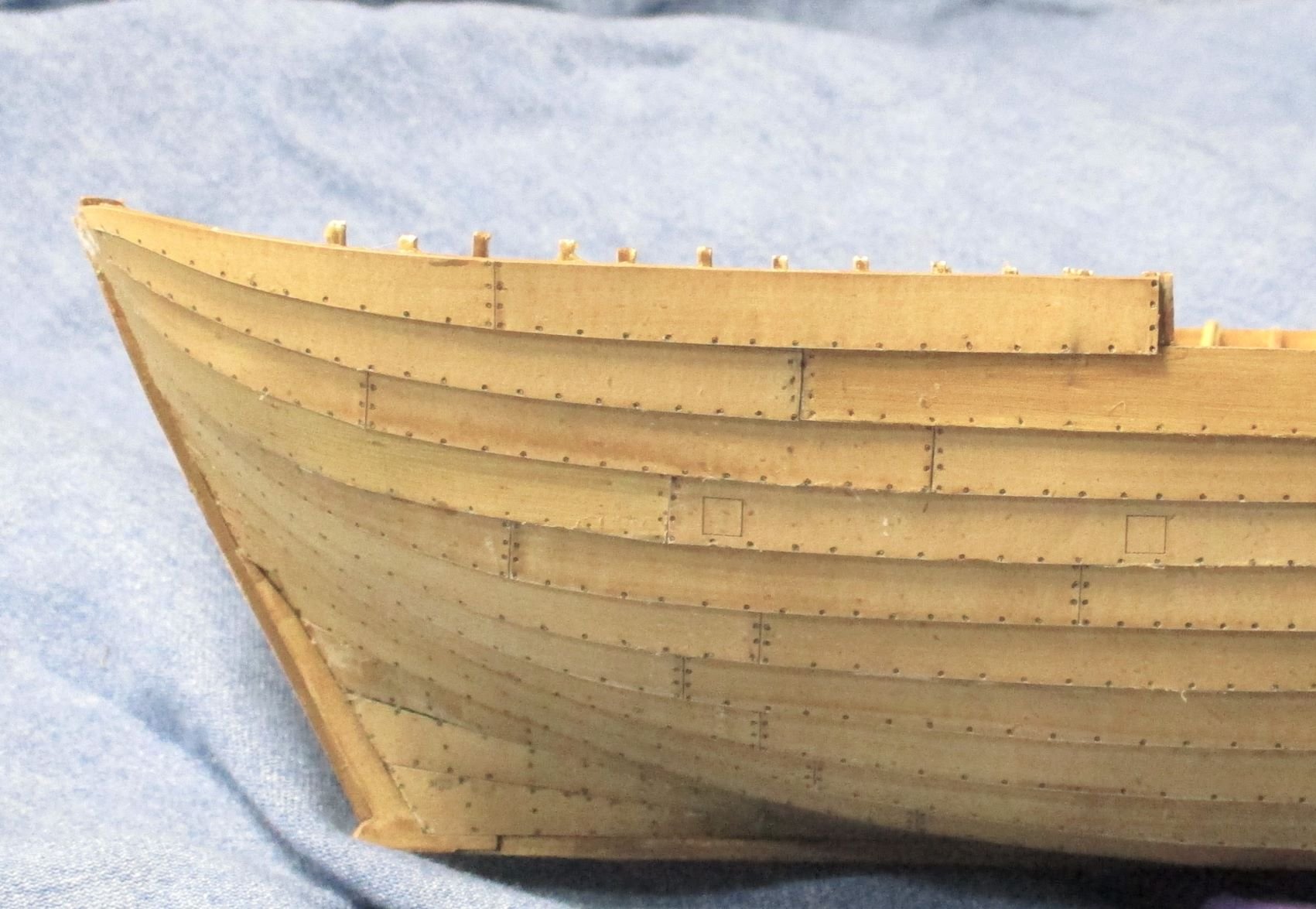
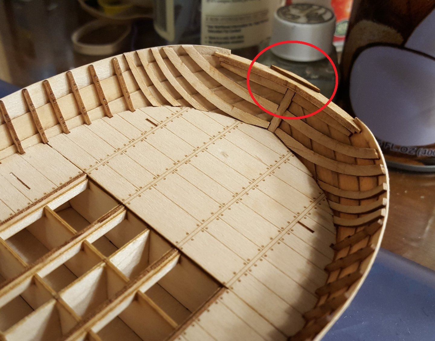
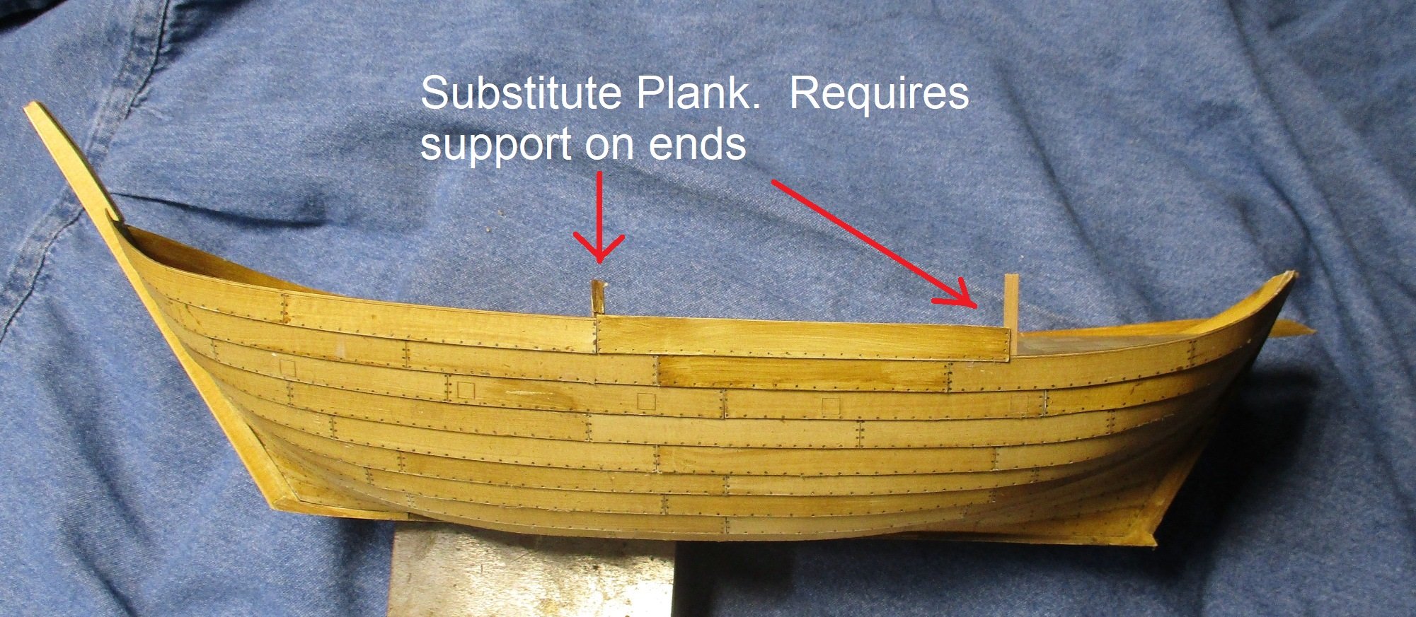
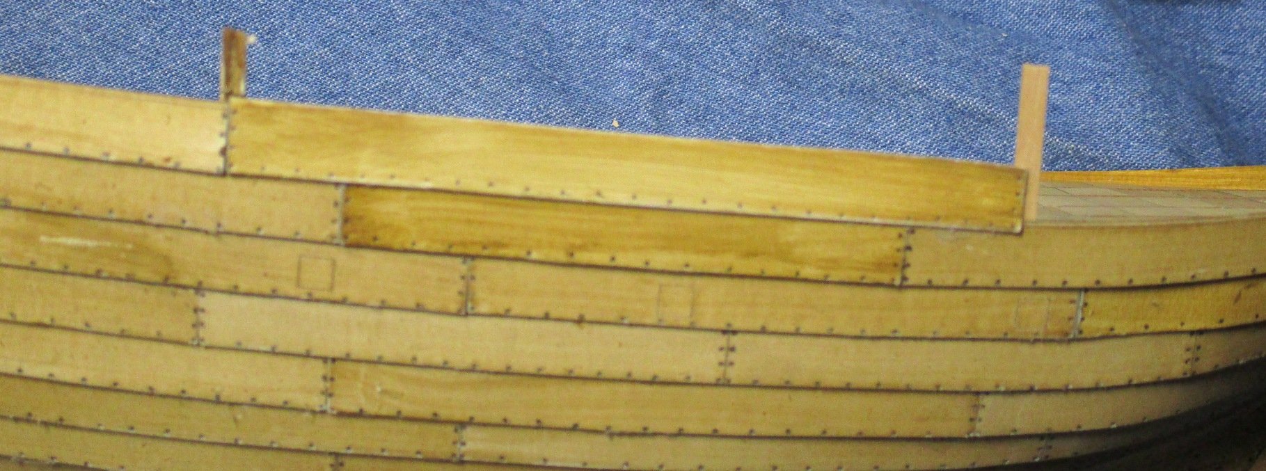
Construction on the hull continues. So far so good, as long as you don't look too close. That's a better look. Clinker + a bunch. We are now cresting above the deck. As mentioned above, I am finding the strake about .25 inches to short, so I need to cut out a plank and insert a longer one. Close up of the plank. Painting is not as good. Long story. Same plank, inboard side, showing supports. The support on the right is a kit supplied double thick frame extension, placed there due to butt joint. The one on the left is self made. The kit was not supposed to have an actual but joint here.


- 130 replies
-
- 8
-
-
- wütender hund
- hanseatic
- (and 2 more)
-
I used Golden Pecan either for the interior or exterior of my PHILADELPHIA. It's a great color...good choice. The nails look good without the pencil dots. Are you staining the interior as well? If so are you using oil based or water based. My concern is for the glu-ability of interior frame extensions and other support lattices.
- 179 replies
-
- 2
-
-
- shipyard
- wütender hund
- (and 1 more)
-
My decks are wood and I gave them a coat of Wipe On Poly. On my first extension, it stuck to the planks but not the deck. For follow-on extensions, I had to rough up the spot on the deck a little.
- 179 replies
-
- 2
-
-
- shipyard
- wütender hund
- (and 1 more)
-
For me it is more than 37...or maybe 37 with complications. Since I am having to cut some of the planking pieces and inserting longer planks (see above)(edit...oh wait, this is your log, not mine...see my log for discussion on planks) I need double thick frame extensions at the point where the joint is. So far so good.
- 179 replies
-
- 2
-
-
- shipyard
- wütender hund
- (and 1 more)
-
An Amati kit with a defect? This is my shocked face. Seriously though, you should be able to repair with a touch of sandpaper. Hopefully you will be painting the hull.
-
Seats of Ease
Chuck Seiler replied to TKAM's topic in Discussion for a Ship's Deck Furniture, Guns, boats and other Fittings
Was that really all that extraordinary? How did the common folk on land 'answer the call of nature'? -
Progress on hull planking continues. Pictures on the way. I just wanted to post as potential warning for other builders. Progressing past clinker +6 I am finding that EVERY strake is about a quarter inch too short. I am not sure why because I am hitting all my other reference marks. I fixed the problem by laying the forward most piece (usually 2 planks), cutting the first plank from the aft piece, making a plank to make up the difference in length, lay that, then lay the last section so it ends up where it is supposed to be in the stern. So far so good, but it is annoying.
- 130 replies
-
- 2
-
-
- wütender hund
- hanseatic
- (and 2 more)
-
When all is said and done, by the time you get the stain and no pencil dots, the existing 'nails' will be visible but sufficiently subdued so as not to overwhelm the model, like on mine.
- 179 replies
-
- 2
-
-
- shipyard
- wütender hund
- (and 1 more)