
Chuck Seiler
-
Posts
1,878 -
Joined
-
Last visited
Content Type
Profiles
Forums
Gallery
Events
Everything posted by Chuck Seiler
-
 Some day I am going to have to take a course in "The French Curve". I can never seem to get the right curves matched up.
 -
Mark, Yes, the bottom hull plank should connect to the outer most floor/bottom planking. You would be correct in beveling the bottom to match the curve in the hull. Apparently when they built the Philly, they started at the bottom and worked their way up; cutting off whatever frames (and eventually stem) that stuck up above the last strake. With the model, we start from the top and work down. Chances are good that the bottom strake will extend past the floor and will need to be sanded down...but that's okay.
-
Brian, Understood. Keep in mind that I have been doing this awhile and this is my second PHILLY. As I find things out for my build, I am explaining hat I am doing and passing it on to other builders. They can do what they wish with it. I am hoping that by doing this, builders can better understand the build and may be able to upgrade/bash their model. With this in mind, you might be prompted to use the two strakes, as indicated in the plans, but not to caulk. Good luck. The model out of the box is pretty terrific.
- 259 replies
-
- 1
-

-
- Gunboat
- Philadelphia
- (and 1 more)
-
Go with the dimensions on the plans. If I recall correctly, the sheer strake = 3/16" and second = 1/4". When combined, this pencils out to just under 1/2 inch. .
-
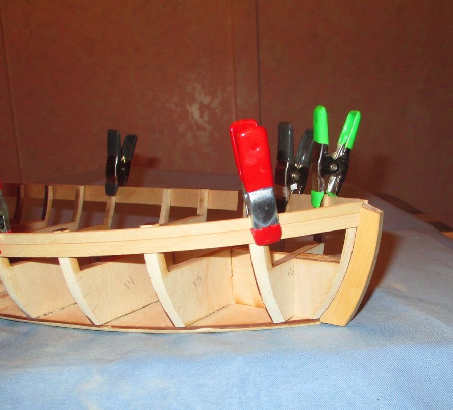
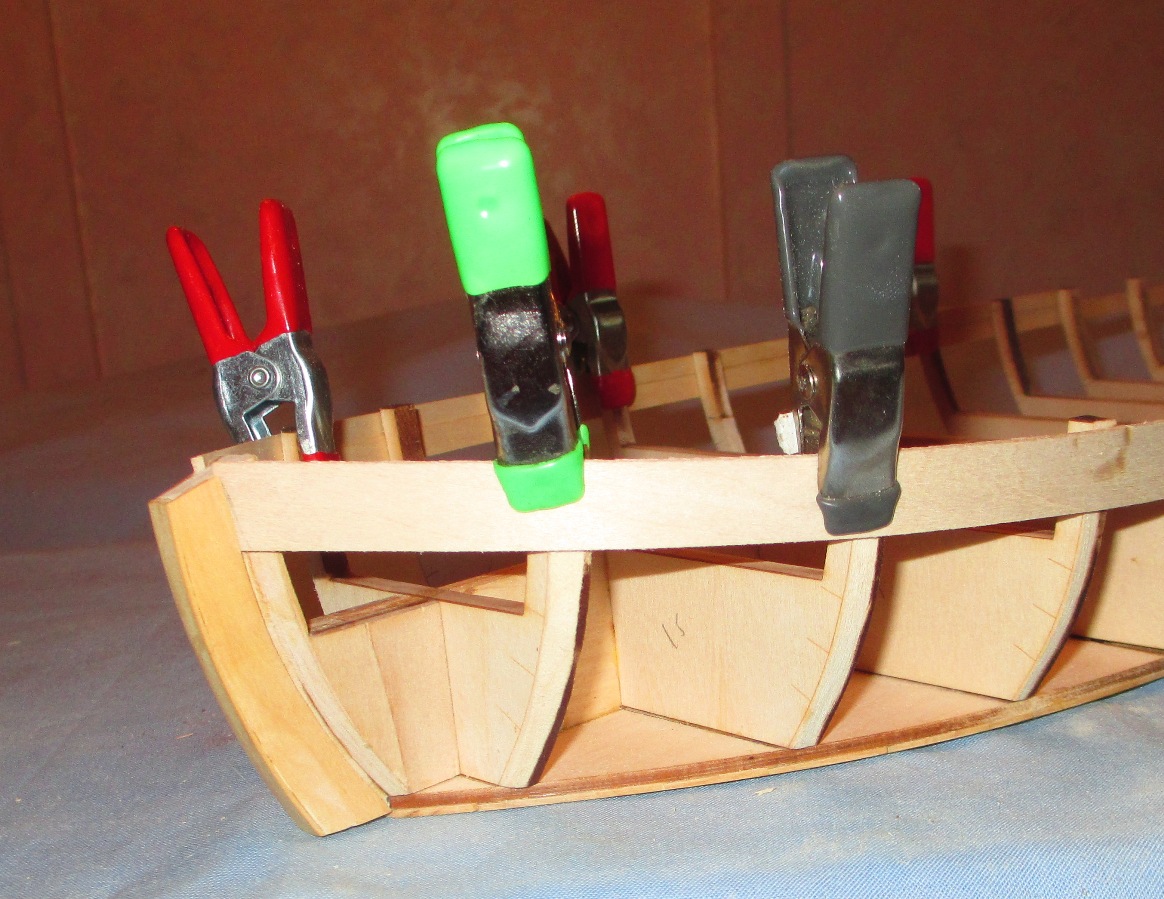
Off on another side trip, for reasons explained below. I rough faired the frames and test fitted the top strakes. Reading BRATTEN, I got a strong impression that the Model Expo plans were incorrect and there was only 1 strake above the wales...it was the width of the two strakes ME used. Specifically, he refers to the wale as being 'directly under the sheer strake. Also, when discussing exterior planking he says there are five strakes and a wale. Clearly there are four strakes below the wale. I consulted Dave Yotter. He said to go with BRATTEN. Why did ME go with two strakes above the wale? I don't know. Perhaps with a wider strake you would have to spile and they wanted to avoid that. I went with a wider piece of basswood, slightly wider than what strakes 1 and 2 are combined. It appeared to go in very well. I intend on going with the single. I will keep you advised. For those going two, I recommend NOT caulking between them The reason I went with dry fitting the planking a little early is because I needed to fit the deck beam for frame 12. Once I had cut away alot of the bulkhead, the frames got relly springy. I had marked where the beam SHOULD be and I was pretty sure of the length of the beam, but I didn't want any surprises come planking time. I set the planks and fitted the beam to those dimensions.


- 259 replies
-
- 2
-
-
- Gunboat
- Philadelphia
- (and 1 more)
-
Dave, Absolutely. He gives a good overview of the military and political situation in order to set the stage. "Benedict Arnold's Navy" goes into greater detail, but as a single source, Batten is pretty complete. He then burrows down a bit and talks about building the fleets. He has a chapter on each. other chapters include the lead up to the battle and one on the battle and its aftermath. The mother lode is/are the two chapters on "construction" and "artifacts". There you get alot of details. If you are going to bash the kit or build it using ME plans, this is the way to go. If you want to build a full on scratch, also get the Smithsonian plans.
-
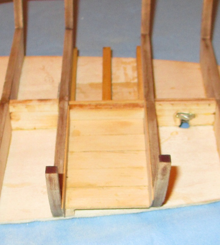
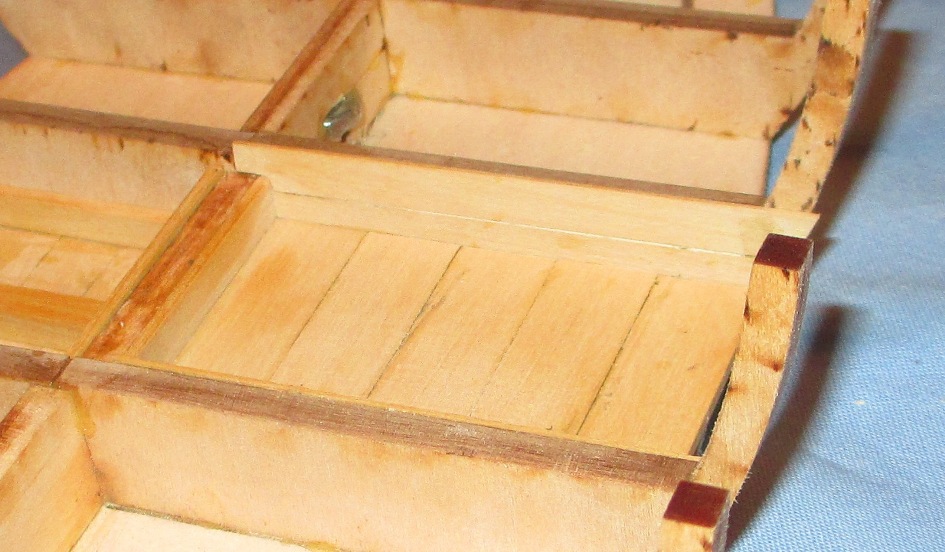
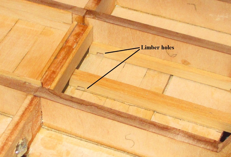
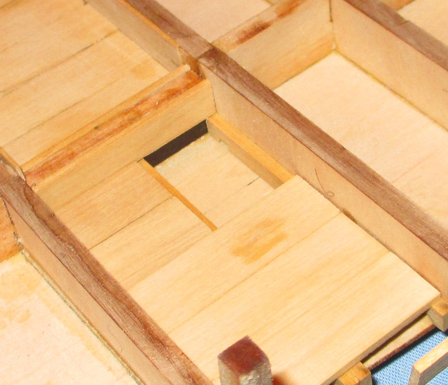
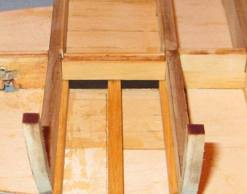
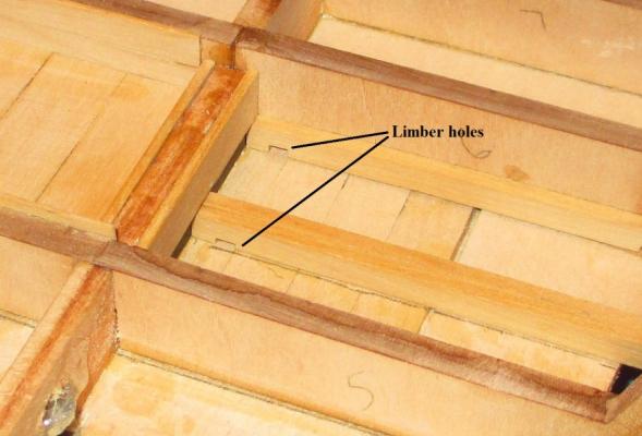
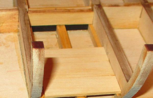
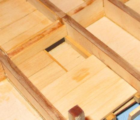
The following few sections include modifications to the kit. Some of these were planned/considered before I started. Some were a result of revelations after reading BRATTEN a little more thoroughly and consulting with Dave Yotter. Because they are modifications to/variations from the kit plans, I feel it is important to include the "why" as well as the "what" and "how". Once again, a major shout out to Dave Yotter and his 1:16 Philadelphia. He is using the plans from the Smithsonian which were a DIRECT result of the survey. While the plans are too brittle to bring to the meetings, he has shared info with me. It's not like they are original plans, or anything. He has just been working on it for a longtime. Rumorhas it that he actually consulted with Benedict Arnold to get info on some of the original construction techniques. Just sayin'. Floor planking of the port side of the aft cockpit. Pretty straight forward. Here I planked the aft bulkhead of the aft cockpit. Dave's Philly has the top plank removed. I ill stick with the kit on this one. Oh, that's right, the kit doesn't plank the cockpit bulkheads. Fore and aft bulkheads of the aft cockpit are both planked. Moving over to the strboard side, we see alot of changes. I was reminded that the keelson sits on the floor timbers. at this point it would be a real pain to cut away that part of the keelson, so I removed the wood piece attached to the right side of the keelson and inserted a piece of wood 1/32" thick painted black, cut the wood piece I just removed and replaced it on the floor beams. BRATTEN indicates there were limber holes in each floor timber, on either side of the keelson. Looking at Dave's Philly, the bailing well is the entire length of the aft cockpit. I decided to go with the kit dimensions. It makes it harder to see the painted slot "under" the keelson. BRATTEN indicates that there was probably a lid on top of the bailing well, but floated away when the boat sank. That kind of makes sense. A continuous flat surface would create less of a trip hazard. All these still need to be smooth sanded.


- 259 replies
-
- 3
-
-
- Gunboat
- Philadelphia
- (and 1 more)
-
Yes, it is a massive beastie.
-
No need for a stand for the ship. It's flat bottomed. However, its not to early to be thinking about a display stand. See my post about that.
-
Oh my!!!! The Chicago area has 3 mighty fine clubs. We need to get you connected. Kurt Van Dahm, who is doing the SIS article, is a member of one of them. A cradle to hold the Dremel or the model?
-
This kit building group is a rough crowd. If you dawdle for a few days you drop down to page 10 and get a vagrancy citation. I have been semi productive, but not in any particular order. I have doing some more research, scoping out nail patterns and stuff. Mostly I have been working on my non-kit modifications and some planking. While I have not been posting, I have been IMing with Steve. Starting tonight, I will be getting my ducks in one sock so I can post progress pretty close to the order it is outlined in the instructions. Kurt V. D. has a new article out in "Ships in Scale" if you have not yet seen it.
- 259 replies
-
- 2
-
-
- Gunboat
- Philadelphia
- (and 1 more)
-
Mark, Welcome to MSW and welcome to the Philly build. I see you are from Chicago. Are you associated with any of the Chicago ship model clubs and do you know Kurt Van Dahm? He is doing a series of articles in "Ships in Scale" about building the PHILADELPHIA. Looking at your tool selection, the only thing I would add is a Dremel (for now). I use it mostly for the drills and drum sander, but also other things from time to time. The pricier stuff comes later.
-
Kurt, Lookin' good!!!! What size blocks did you use for the guns? As I recall, the plans call for 10MM. The largest Chuck makes is 9MM, but he didn't have them in stock at the time of my last order. I may go with the 9s. Glutton for punishment? Isn't that part of the job description?
-
I had the opportunity to take a good look at Dave Yotter's 1:16 Philly. He is making it from the Smithsonian plans, with a ll the framing and planking per the original. Unfortunately I did not have my camera for pics. He said he would send me some. Dave nailed all the planks,much as Bear did, using the formula outlined n BRATTEN (which I will attempt to extrapolate). I would have thought that all those dots would have been distracting, but they were not. I hope to have some pics soon.
- 259 replies
-
- 1
-
-
- Gunboat
- Philadelphia
- (and 1 more)
-
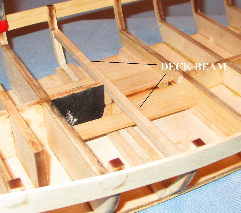
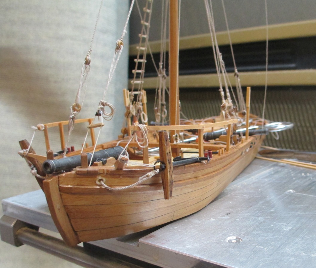
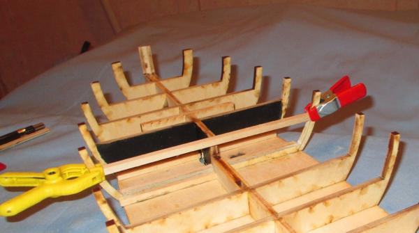
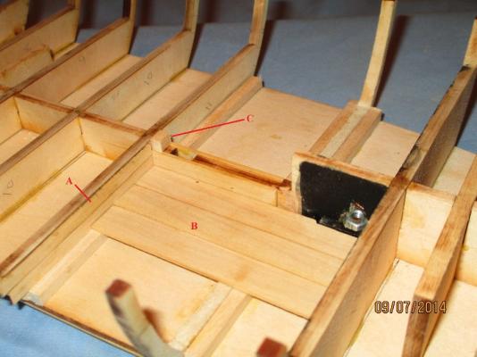
Progress continues. I have installed all frames except 1...#12. As indicated earlier, from what I have read and from what I see in the virtual 3D Philadelphia, I perceive the bulkhead at the back end of the forward platform to be nor solid. Instead it is open and is sort of a crawl space under the forward platform where supplies and firewood can be stored. This means most of frame 12 must be cut away Here we see frame 12 altered. Floor beam and side frames exist. Deck beam is being fitted. Here is some planking progress that is still a bit rough. I will need to smooth it up, but I waned to get in into the log. A- The forward end of the midships platform is planked. I will eventually o this to both bulkheads in the aft cockpit as well. B- Forward cockpit planking continues past frame 12 and on to frame 13. I will eventually put stuff here so you cannot see too deeply into the hold. C- I added a little nub aft of the mast slot. This was/is not on the real ship, however I had alot of trouble with the eyebolt/block assembly at this location in my previous build.
- 259 replies
-
- 3
-
-
- Gunboat
- Philadelphia
- (and 1 more)
-
Keith,. Do you have any pictures? I am intrigued. Start a build log and post some. I know that you are already complete, but this will allow you to post your pics without using somebody else's log. Which 2 books?
- 308 replies
-
- 1
-
-
- finished
- model shipways
- (and 1 more)
-
Steve, That looks good. Did you use pencil for the 'tween plank caulking? I am running a bit behind. As I think I previously mentioned, I believe the bulkhead at the back of the forward platform (in this case, frame 12) was not solid...but in fact open to permit crawlspace type access. I am having some setbacks. :-( I hope to have some pics by tonight.
-
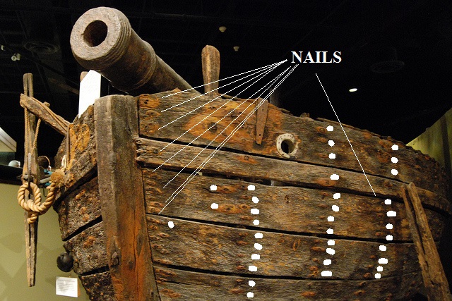
More on nails and nail patterns. As I mentioned above, I will put together a piece on what the nail patterns were based on BRATTEN. However, here is a clarification of a previous post. Here is the previous picture of PHILLY with some of the nail positions outlined in white.

- 259 replies
-
- 2
-
-
- Gunboat
- Philadelphia
- (and 1 more)
-
Mark, Chapter 8 of the dissertation Bart linked to in post 101 is almost the same as chapter 7 of the book. I will compare the two later this weekend, but reading the book I see that in some cases the number of nails or treenails are given precisely and others estimated. From my readings it appears to be a case of "nail the crap out if it, where ever needed" as opposed to any particular formular. I kind of glossed over that section (construction) when I built the first time because it was alot of stuff at once. As I look at it again, I am finding alot of good stuff and since I plan on more detail, it helps alot. I was incorrect in saying there were 32 frames, there were actually 39. Since we don't plan on nailing until later, my plan is to go thru the book chapter 7 and come up with the specific nailing numbers for each section. He divides it into lower (underside) planking, interior floor (ceiling) planking, interior side (ceiling) planking, exterior planking, the wale, deck platform planking. Should I present this as a post or as an enclosure to a post? Kurt, do I get my NRG "research ninja pin" for this? POST SCRIPT. Different designs/different builders? Eh? More like an organized cluster-goatrope. If you read the early chapters of the dissertation you get a feel for what they had to do to get these things into the air...er ah onto the water. 8 gunboats and 4 row galleys over a couple months time in the backwoods of nowhere using prety much green wood, with an unknown number of carpenters and shipwrights coming and going based on a design that nobody knew. Apparently Arnold wanted the gunboats to be like the ones on the Delaware. Nobody knew what those looked like. However, they had been building bateauxs on the lake for decades. The gunboats appear to be based on those designs with the frames massed produced. The boats were slapped together in three weeks, with pieces dissembled later in order to place armament and other items once the boats got to fort Ticondaroga for fitting out.
- 259 replies
-
- 2
-
-
- Gunboat
- Philadelphia
- (and 1 more)
-
That is John Bratten's dissertation (doctoral dissertation perhaps?) on the wreck. While not word for word, it appears to be the basis of the book I cited. This was dated 1997 whereas the book was published in 2002. With the exception of a few flourishes, I suspect the info is the same. Good find Bart!!! I did not recall the part about the floorboards being connected with trunnels. I will have to re-read that. My recollection was of the replica using trunnels and my thought at the time was that they expect the replica to last more than 2 months. There is evidence (as cited in the dissertation and book) that they actually installed one of the mortars in PHILADELPHIA and it exploded while testing there-on. The other blew up upon testing as well. He says there were square openings in the inner planking indicating where the mortar may have been mounted (on the aft platform), but the Model Expo plans do not show that detail. Another "Oh crap" moment from the book. When they went to mount th eforward 12 pounder, the stem was inthe way and had to be cut down. Ooops!
-
I was thinking of taking a stab at Ed Tosti's method of using mono-filiment...probably grey, if available. However, given the number of nails, this would be overwhelming. I figured the number at one point. I don't remember what that was but it falls into the category of "butt-load". To answer Steve's question on his log...Each plank is nailed at each frame-1 nail for every 4 or 6 inches of width(I would have to recalculate). Remember, the kit only uses half the number of frames the real boat had, so plan accordingly. This gives you a rough idea what kind of measles infested beast it will look like. PS...All those little dimples are the nails.

-
Over on Steve's log we were talking about nails. Based on observations of the actual hull and pieces-parts/artifacts outlined in John Bratten's book, the nails were no more than 1/2 wide. By my calculations that would be .02". At that scale, I don't think that the fact they are square makes any diff. We are discussing this now, with the plan that at some point we may or may not "nail" the hull. Out to the peanut gallery for thoughts/comments. Hey!! I made LCDR. It only took 28 years.
- 259 replies
-
- 2
-
-
- Gunboat
- Philadelphia
- (and 1 more)
-
Continuing on this thread, while we are here, by my calculation, 1/2 inch is .02". I don't have my caliper available, but my recollection of an .020 saw blade, this is about the size of a semi dull pencil point. What does the peanut gallery say? Continuing.
- 308 replies
-
- 2
-
-
- finished
- model shipways
- (and 1 more)