
Chuck Seiler
-
Posts
1,879 -
Joined
-
Last visited
Content Type
Profiles
Forums
Gallery
Events
Everything posted by Chuck Seiler
-
 Frankie, I disagree. I see no issue with including SOME detail at a certain granularity, but not include all. I suspect we already do that. If you rig a ship without sails, don't you leave off some of the rigging? Some people rig the guns to a gnat's ***, but do the really model in every rope, line, bucket, widget and who-ha that might be on deck?
 -
All good points. I think that the better you get, the more detail you can put into your model. One reason for this is because you are getting better and can do things quicker. If it takes you forever to do the basic stuff, it will take several forevers to make it detailed. Secondly, when you get better your quality improves. Crappy details don't improve crappy models (trust me on that one). However when you have a quality model, quality details improve it. That having been said, there IS such thing as too much detail. I think scale dictates that. Sometimes you can overwhelm a model with too much detail. Personal preference. Take a step back and let the model tell you what is right. Who is your audience? If you are doing if for just yourself, make it for you. If you are making it for the public to see, remember people will only look at it for a few minutes, then go away. Some will look for 30 seconds some for 10 minutes. Make your model so it appeals to all of them in its own way. ...and whatever level of detail you decide upon, make ONE thing significantly more detailed. People will focus on that, you will get your "Holy Cow!!!" and people will walk away with a feeling it is far more detailed than it really is, because of the one they fixated on.
- 55 replies
-
- 19
-

-
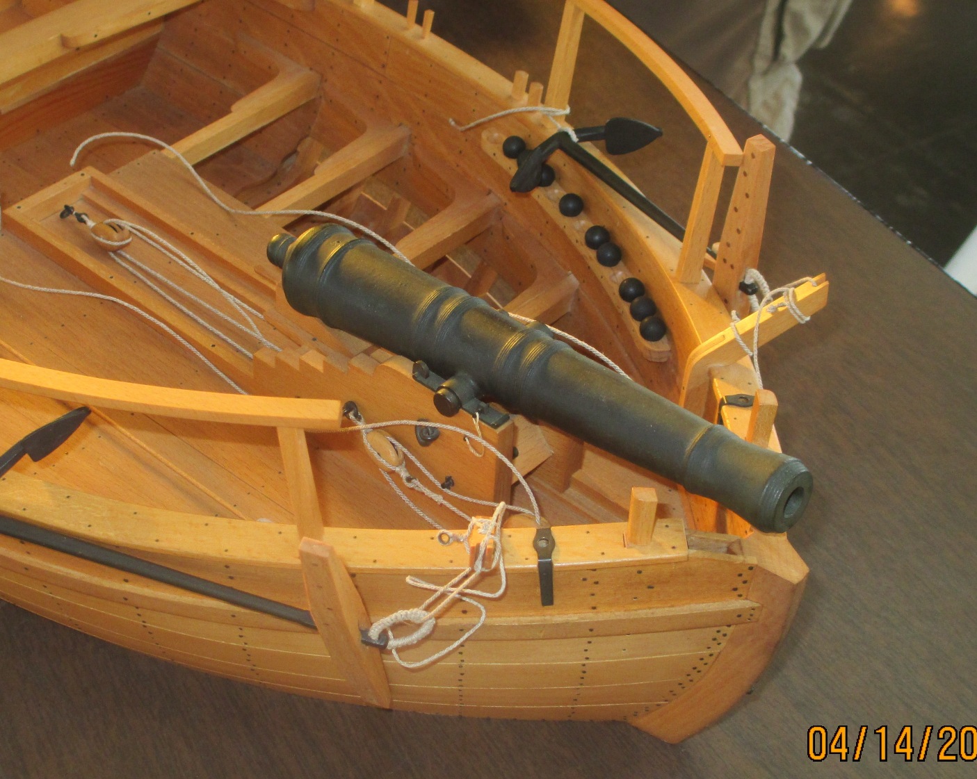
The Smithsonian 3D scan is of the ship as it is now. That includes all deterioration. Notice the gaps in the planking. . Above is a picture of Dave Yotter's PHILADELPHIA (taken from our recent ship model Guild meeting) built from the Smithsonian plans. Note how the curve of the caprail trends upward until it abruptly ends. That's where it was chopped off. You can that, if left in place, the operation of the forward gun would be impaired. Unlike the Model Expo plans, the Smithsonian plans are structurally correct. If you blow up the pic, you can see that the gap is indeed open and you can see into the innards. Kurt's replication is about the same. As previously discussed, they were not too concerned about water getting in there and rotting the insides out. They knew it would not be afloat long enough to worry about.

- 259 replies
-
- 4
-
-
- Gunboat
- Philadelphia
- (and 1 more)
-
I left the innards exposed. A half inch seems excessive. I have not gotten to that point yet with Philly 2 so I am not sure of the distance (I guess I could measure). I'm thinking a half inch total...but I understand what you are saying. In real life that happened because they didn't plan very well and the bow was too high for the gun to clear....so they sawed off a chunk. On Philly 1, that area is reinforce with sold wood, so I painted it black to appear open. The 12 pound forward gun covers some of that, but not all.
- 259 replies
-
- 1
-
-
- Gunboat
- Philadelphia
- (and 1 more)
-
I built the FAR WEST about 10 years ago. It is here in my office at work and I gaze upon it as we speak. As part of doing research, I was amazed at where those things could go. While the Mississippi boats and Missouri boats has a lot in common, it was two different worlds. The interior passenger areas were pretty luxurious (for their day) but with limits. Note the two "rest facilities" at the aft end of the upper deck, just forward of the paddlewheel. Two seats, no waiting!!!
-
I might be tempted to use a red auto primer. I know its not acrylic, but....if I recall from my Navy days, it is close to anti fouling red. With reference to water down ratio, I would say to experiment. When I water down artist acrylic, it is heavily pigmented water. The first coat is translucent...you can see the base below. The second, third and fourth coats do the job. I let dry and sand with 1200 sandpaper (first 2 coats) or buff with cloth. It works great on wood, but I'm not sure how it will work on plastic. You may need a slightly different technique.
-
Pics! Pics! Pics! Pics! How did you end up doing your lower dead eyes? I remember having a tough time with those. ...tying the knots in the right place after running the line thru the hole in the hull was difficult. I think what I ended up doing was determine where the know should be. Tie it BEFORE putting it through the hole, making it about the same size as the hole. When I pulled the knot thru the hole, it was hard, but with a little effort I pulled it through and it was not going back.
- 308 replies
-
- 1
-
-
- finished
- model shipways
- (and 1 more)
-
Thoughts in general: I have had a lot of success hand painting with Badger acrylics. Even better when thinned down, a Nenad suggests. I have had good success using artist acrylic (from a tube) watered down as well. I got this from Chuck's discussion in his Winchelsea (?) log. (Confederacy maybe). Thinned down to almost water, multiple layers until you get the finish you like. It works great on wood. I assume it will work on plastic as well. So far I have only used black. Red is n my future
-
Will it fit a Byrne's Saw? I imagine a feather board will work as well.
-
Which project do you start first? The model or the room addition used to store the model?
-
Rgr that. I think he was just asking if the issues you noted were available.
-
I am assuming so. Contact the Ships in Scale folks. Check out the following: http://www.seaways.com/Back%20Issues.htm
-
Oh no!!!!! Having had to start over on some projects in the past, I understand to some degree where you are at. Sometimes it is easy to go back and get in the groove. Sometimes not. Enthusiasm is gone and you really don't want to go down that path again. I hope in this case it is the former. I am learning a lot and hope to see you back in battery again soon.
- 172 replies
-
- 1
-
-
- druid
- sloop of war
- (and 2 more)
-
Chuck, When you specify the number of strakes below the wale, to you count to the keel or to the top of the garboard strake?
- 1,051 replies
-
- 1
-
-
- cheerful
- Syren Ship Model Company
- (and 1 more)
-
Chuck, Obvious from your videos, one of the keys to getting it right is ensuring the garboard strake is the correct length. This is something I struggle with. Is there any rule of thumb regarding where it ends?
- 1,051 replies
-
- 3
-
-
- cheerful
- Syren Ship Model Company
- (and 1 more)
-
Not yet. I am still trying to fabricate the bulkheads.
-
Meet Your NRG Directors and Officers
Chuck Seiler replied to tlevine's topic in NAUTICAL RESEARCH GUILD - News & Information
KURT! KURT! KURT! KURT! -
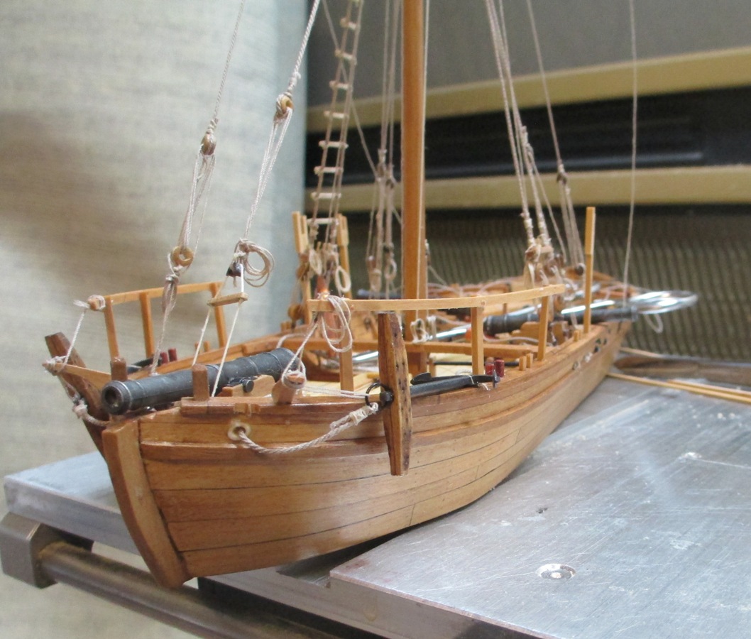
Can you remove the gun or is it attached permanently? I think it is easier to rig the carriage, get it into position, then remount the gun. IIRC, I rigged the running tackle with the gun extended, anchored one of the breeching line eyebolts (with line attached), THEN hauled the carriage into place. As I said, it may be easier with the larger scale. New project: Colonial sloop PROVIDENCE.

-
Steve, That's looking really good!! Wait 'til you start securing all the lines and bolts and stuff up at the pointy end. Hopefully it will be easier with the larger size.
-
For some reason, I am not getting email notifications on the builds I am following, so I did not see this earlier. As I have told Steve, I have stalled on this project because I am obsessing over the nails. Your nailing looks pretty good...although I think you are using 1 less nail/plank/strake (based on Smithsonian ship). While not historically correct, after looking at your pics, I am thinking about going with the reduced number of nails.
- 259 replies
-
- 1
-
-
- Gunboat
- Philadelphia
- (and 1 more)
-
Clare, Greetings once again. Based on your post, I checked Amazon for the HK. The only one I found on Amazon (9 left) wanted $419.99.
-
I believe the Lumberyard ONEIDA employs similar frame construction.