Chuck Seiler
-
Posts
1,878 -
Joined
-
Last visited
Content Type
Profiles
Forums
Gallery
Events
Everything posted by Chuck Seiler
-
 What,no pics?
 -
Wow! Great job. I am glad to see you have been working on this. I feel bad about slacking off. (but not real bad) Which coils? On deck or rigging coils? In both cases I made the coils as separate entities and glued them over the loose end of the line. The coils for the running rigging was the biggest pain because there were so many of them. I used the handle of a small file to make the coils. I made several (6 or 7) wraps around the handle and tied an overhand knot to keep it from unraveling. I also coated it with diluted white glue. The handle was smooth and tapered so it was easy to slip the coil off once the glue dried. I slipped the coil partially off so that I could wrap part of the overhand knot line around the coil and knot it so it would not unravel. This was tricky and was the point many of my coils failed. One end of the line is cropped and hidden while the other is allowed to hang out as if the bitter end if the line.
-
I had the same issues/concerns with schooner SULTANA. My initial thought was that the cable was wrapped around the portion of the barrel outside the frames, but that puts a very strange angle in the line between the hawse, the windlass and the grating where the cable goes below deck. Since there are two anchors, if they used the procedure outlined by John, would they just disconnect the cable from the unused anchor and leave it hanging from the cathead?
-
Oh! Eyebolts, not grommets. Yes. Some people paint. I used "Blacken it", which takes more effort, but I think the result is better. <it's late.......>
- 308 replies
-
- 1
-

-
- finished
- model shipways
- (and 1 more)
-
I'm not sure what the instructions say. They look white on the SMITHSONIAN model. ....so that's how I made mine. I used styrene tube.
- 308 replies
-
- 2
-
-
- finished
- model shipways
- (and 1 more)
-
What next?
-
Lookin'good. I am about to post some myself, but I am not as far along as you. I don't see the grommet on the inside.
- 308 replies
-
- 1
-
-
- finished
- model shipways
- (and 1 more)
-
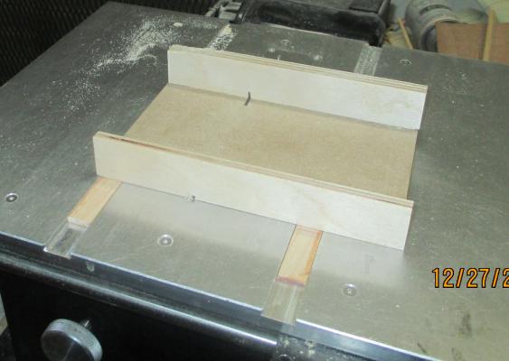
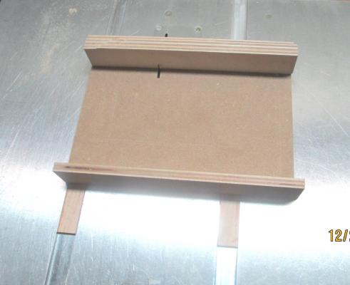
Gosh...I got a sled for Christmas. This does not have a sawcut all the way thru the bed yet. I did my initial cuts with a larger blade. I will make my final cut with my .030 slitting blade, the one I will use with this. My thanks to Krug for his directions.
- 259 replies
-
- 4
-
-
- Gunboat
- Philadelphia
- (and 1 more)
-
1/32" planking...yowza!! Mighty thin...not much there for sanding. Where will those planks go?
-
Can i live without a BYRNES TABLE SAW
Chuck Seiler replied to shihawk's topic in Modeling tools and Workshop Equipment
Agreed. My point was that you don't NEED those tools if you want to scratch build but don't have a shop full of tools. I functioned very well for many years with my Dremel, exacto and sanding block. One day I got a Byrnes saw and the world opened up for me. Since then I started scratch building. I have now purchased a disc sander and expect my model building experience will gt easier and models better. Some day I will get some other thingamajig when I see a need for it. -
Can i live without a BYRNES TABLE SAW
Chuck Seiler replied to shihawk's topic in Modeling tools and Workshop Equipment
That depends on what you will be scratch building. I have been scratch building (although not necessarily scratch completing...but I digress) for years. The Byrnes saw and a handy Dremel are all the power tools I used. I was doing plank on bulkhead. If you plan on going plank on frame, using , say, the Hahn method or the Antscherl method, I think a scroll saw will be needed to cut out the frames. -
mini drill chuck for those small drill bits
Chuck Seiler replied to AON's topic in Modeling tools and Workshop Equipment
Another option http://www.amazon.com/Mini-Drill-Chuck-Shank-Micro/dp/B001S00FYM/ref=sr_1_29?ie=UTF8&qid=1418837229&sr=8-29&keywords=dremel+micro -
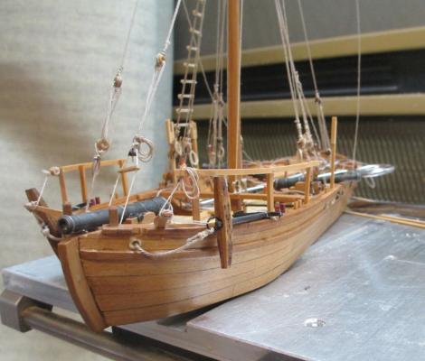
I was just browsing your log and found this...sorry for a belated response. I believe that the "Arrow" is a fictitious vessel. However, I think it is patterned after the gunboat "ALLEN". I have the kit (and still have not built it), so I was somewhat aware of the kit when I heard a presentation in 2001 or 2002 by Dr. Kevin Cristman from Texas A&M University on the "ALLEN" and it's recovery from Lake Champlain. In a side discussion he was talking to somebody about how the ALLEN and kit ARROW differed, but I don't recall the details...but it is close.
-
Mark, I think I am on the same page now. As the frame is sitting in the sled, the cut is 90 degrees from bottom to top, but the actual cut still needs to be eyeballed in order to conform with the line on the template. The cutline in the sled/zero clearance slit lines up with the intended cut line on the frame.
- 172 replies
-
- 1
-
-
- druid
- sloop of war
- (and 2 more)
-
Does that answer the question? Not really. I understand how you get the 90 degree line on the template to begin with, but I don't understand how you get a good cut without just eyeballing it. As I see it, because the futtocks are curved, you may not (probably won't) get a true right angle cut if you brace the futtock on the back wall of the sled. DO you have a pic of how the futtocks sit in the sled?
-
Bob, Good luck with that snow stuff. You are gone for a month and the Guild goes to crap and our meetings are getting cancelled. COME BACK!!!!! Anywho, I look forward to HK getting back on track.
-
Mark, When you are cutting your butt ends/join ends, what are you using as reference plane? Obviously you are using the line on the plan, but since the frames are curved, how do you ensure the angle is true?
-
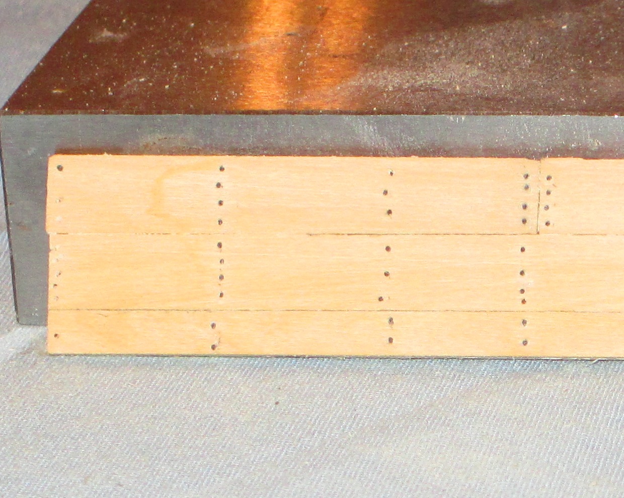
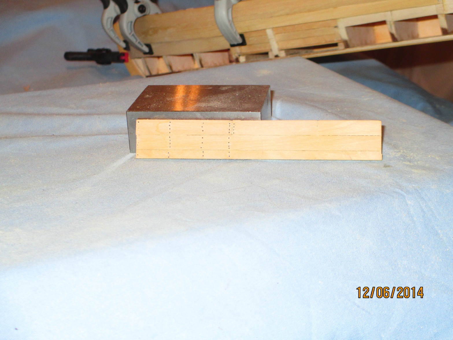
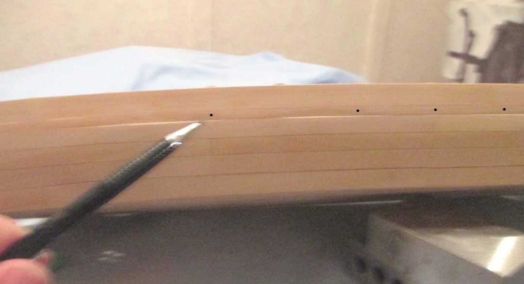
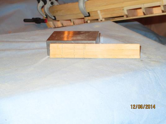
Planking progress continues. As previously reported, I am running some tests on nail patterns. I decided to go with black monofiliment line. I think I figured half inch nails would have been .020". I got close to that with .5MM (.0198"). My first test was on boxwood planking the same size (width) a on the model. On the primary width planks I went with the standard 4 nails and a couple spots with 3 nails. Using #76 drill bit, I made my holes, dipped the line end in Weldbond glue and inserted it into the holes. Some I snipped off immediately and some I let dry first. In all cases there was some glue residue and (more importantly) the nail head made the nail more noticeable than I wanted. After the rig had an hour t dry, I sanded don with very fine sand paper. Here it is again from a further distance. I am not wild about it. I think the nails are too prominent. I will stain the wood with pecan and see again. I will also insert nails in the other side after it is stained to see if there is any difference in appearance.

- 259 replies
-
- 2
-
-
- Gunboat
- Philadelphia
- (and 1 more)
-
The 'looking worse in the photo' is actually a blessing. It reveals problems these old eyes miss and allow you to make corrections. When you get it to the point where it looks really good in the photo, it will look great with the naked eye.
-
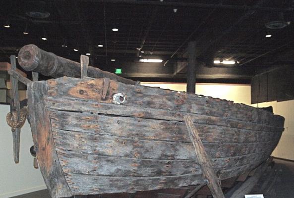
John, Welcome aboard! That certainly falls into the "gee, if I only had a time machine and go back to look" category. I don't know if you had a chance to take a look at all of my scratch log. I go into to detail starting at a later post http://modelshipworld.com/index.php/topic/5721-gunboat-philadelphia-by-chuck-seiler-scale-148-1776-scratch-from-ms-plans/?p=173370 and going on for several posts. Where you see it in the Smithsonian display is where it was found when the ship was raised. The way that it was raised left everything pretty much in tact...even little things that might normally get washed away were still on deck...like human teeth (eeuuyywww!!!). This means that is where it was when the ship sunk and where it was at the time of the battle. This is good evidence to indicate that is where it normally was. However, there is also evidence that it may have been used in the forward cockpit as well (charring on the underside of the mast partner). Because of cramped conditions and the hazards it created, actual use of the stove in the forward cockpit seems awkward as well. My approach? I put it in the cockpit in my scratch build. I may experiment with putting it on deck this time. To me, it seems like having it on deck during the battle would have been awkward and in the way...but there it was. Is it possible that it was normally stowed (and sometimes used) in the cockpit but in this case was on deck on the morning of 11 October, and they were unable to get it stowed in time? Who knows. You could put it in either location and be correct. The on deck location is probably MORE correct because we know it was there. The cockpit location is only speculation.
- 259 replies
-
- 2
-
-
- Gunboat
- Philadelphia
- (and 1 more)
-
Steve, It does, indeed, take time. It is taking longer than I anticipated and I have done this before. ...but it is better to get it done right than it is to get it done fast. Extension? Yeah, I guess that is what you would call it. Just a piece of 1/16" boxwood under each area to even it out. For sanding I use a couple things. 1. A rubber sanding block. 2. Those spongy sanding sheets that curve. 3. Flexible spongy sanding sticks (that look like fat emory boards. I will include a pic when I get home.) The sanding block is just fine if you 'work the curve'.
-
A couple more thoughts: 1. I am at the point where I need to decide whether or not I want to show nails-all, some, none. I have some black mono filament that I will be using. My main concern is that the nailing overwhelms the model. I think t should be subtle. I will be doing some testing over the next few weeks. Will advise. 2. As I was looking ahead, I noticed the instruction does not cover assembly of the cook stove (at least I could not find it). The plan shows it. Parts are provided to build it. The instructions do not discuss it. I recommend you build it and install it BEFORE installing the mast partner.
- 259 replies
-
- 2
-
-
- Gunboat
- Philadelphia
- (and 1 more)
-
Steve, Bottom is already planked. See http://modelshipworld.com/index.php/topic/7451-continental-gunboat-philadelphia-by-chuck-seiler-model-shipways-124-scale-enhanced/?p=230292 The only underside yet to do is the piece under the stem and stern...and sand...and stain.
- 259 replies
-
- 1
-
-
- Gunboat
- Philadelphia
- (and 1 more)
-
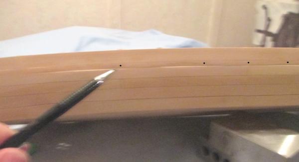
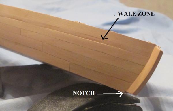
I wanted to take this opportunity to drill bolt holes in the wale for the main gun deck support knees. These were not shown in the model plans but were in the Smithsonian plans and the Yotter model. I originally had pencil dots, but they didn't show up.
- 259 replies
-
- 5
-
-
- Gunboat
- Philadelphia
- (and 1 more)
-
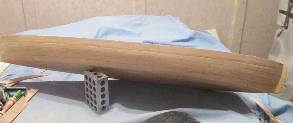
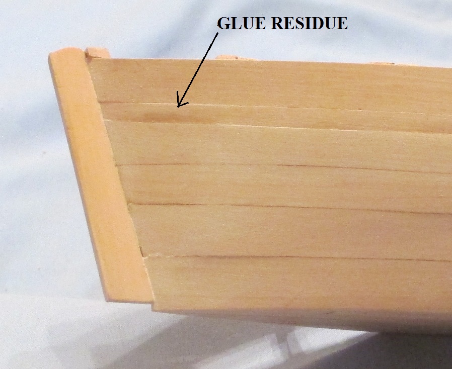
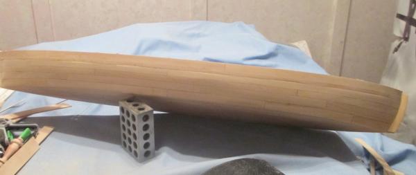
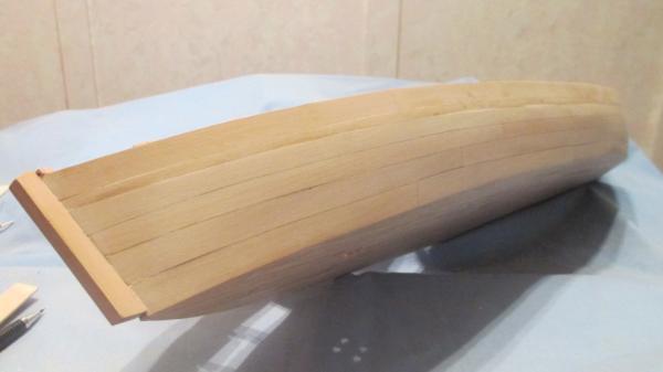
Huzzah! I finally have the side planking done....for the starboard side. I would have posted pics sooner except I was using it for a Thanksgiving garnish tray. I am relatively happy with the result. There are areas that need work, but over all... It looks alot better in real life. The camera reveals alot of flaws. I think the plank joints with the stem looks good. I need to add some stock on the underside of the stem and stern pieces due to the underside planking I added. The sanding job in the area of the wale is less than great. It doesn't matter because I will be adding an additional layer there soon. While I had not planned it this way, the slight depression will help me place the extra layer. From the other end. I see some areas that need work. Close up of stern. Alot of sanding dust still there. I had originally wiped the model down with an alcohol soaked rag; enough to wipe the dust but not so much as to affect the glue joints. The alcohol evaporated quickly without raising the wood grain. One benefit was to reveal glue residue. While the glue evaporated quickly from the wood surface, it soaked into the glue residue on the wood surface. This made it very visible and easy to scrape off using a scalpel.

- 259 replies
-
- 4
-
-
- Gunboat
- Philadelphia
- (and 1 more)