


_SalD_
-
Posts
806 -
Joined
-
Last visited
Content Type
Profiles
Forums
Gallery
Events
Posts posted by _SalD_
-
-
-
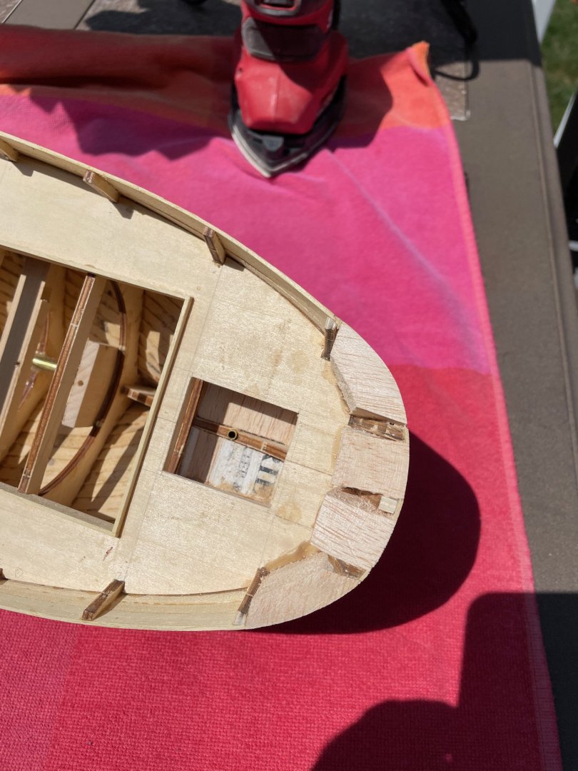
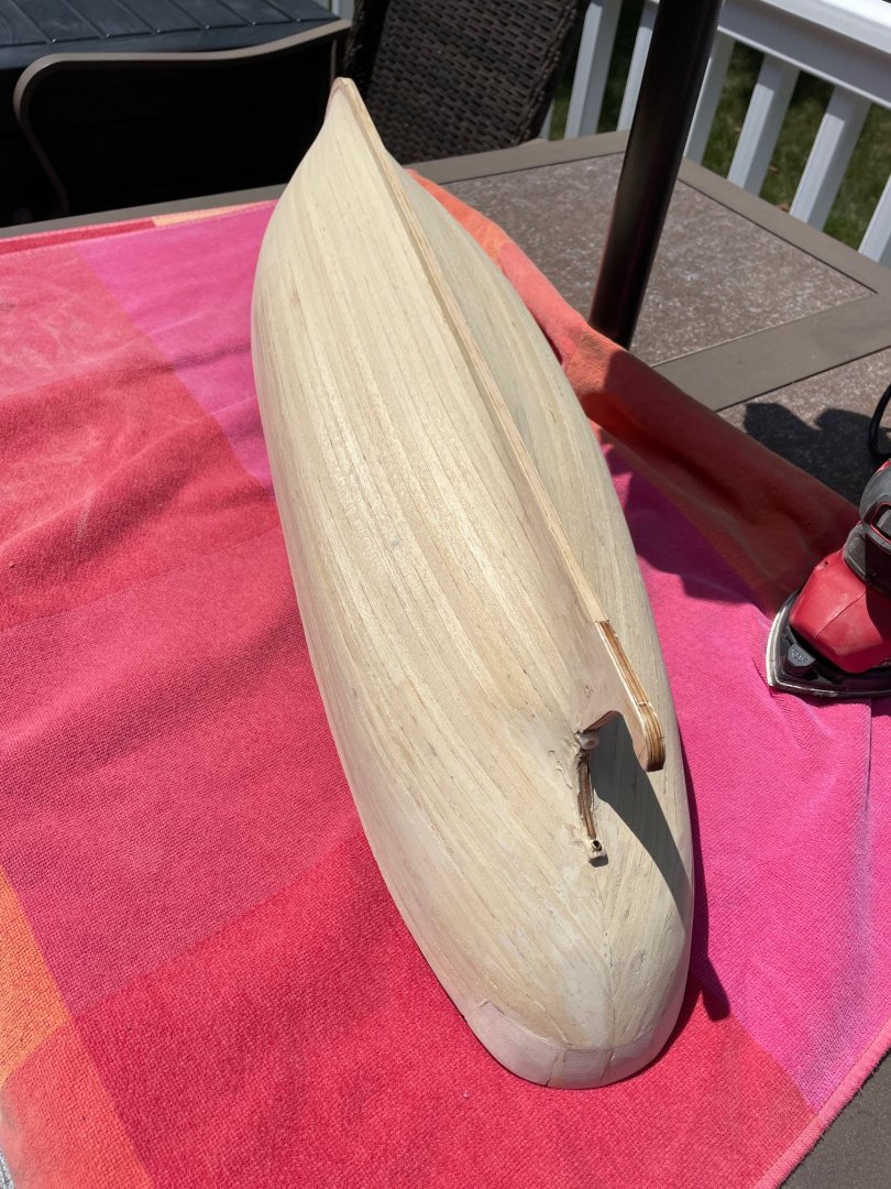
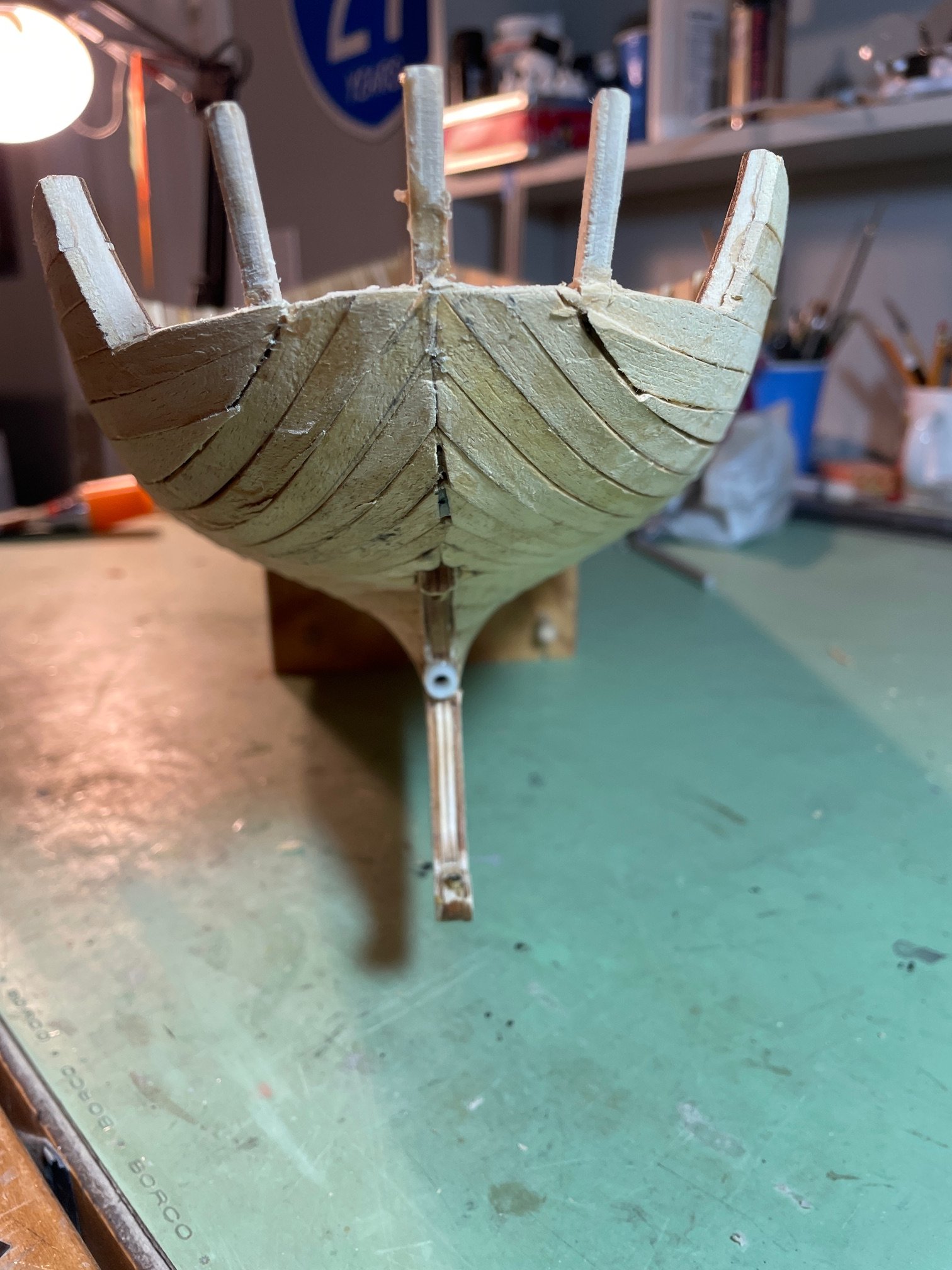
Sanding the Hull
I sanded the hull using my favorite palm sander with 220-grit sandpaper. I know that might seem a bit aggressive, but with a light touch, it works very well.


For the stern, I chose not to use the thin wooden veneer sheet provided in the kit to wrap around the aft bulwarks, as I couldn’t get it to form a smooth, even curve. Since the aft bulwarks will eventually be covered by the pilothouse structure, I decided instead to fill the space between them with balsa wood blocking, then sanded it down to match the shape of the stern.

- woodartist, king derelict, Paul Le Wol and 4 others
-
 6
6
-
 1
1
-
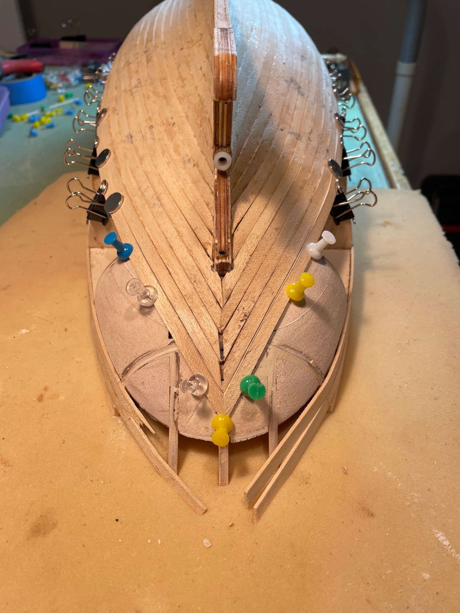
"Planking is complete; now I just need to fill the gaps and start sanding.
The stern still needs a bit of work."

-
18 hours ago, yvesvidal said:
Beautiful planking. There is a lot of care going into it and it shows.
Thanks Yves I appreciate the comments. And thanks for the likes.
-
Planking the hull is ongoing—I'm a little more than halfway through.
I'm approaching the stern planking a bit differently than shown in the instructions.
Instead of wrapping the planks around the stern as shown, I'm running them continuously from the keel up to the three bulwark planks I installed earlier. It seemed easier to shape the planks this way, and it feels like a cleaner fit overall—if that makes sense.


- yvesvidal, robdurant and king derelict
-
2
-
1
-
-
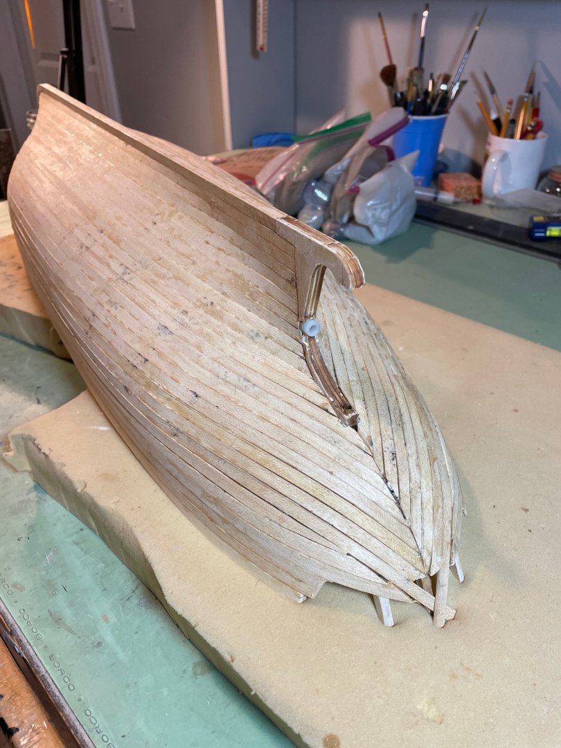
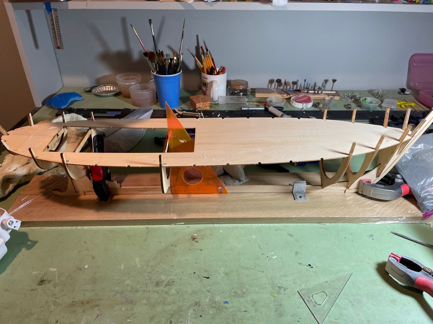
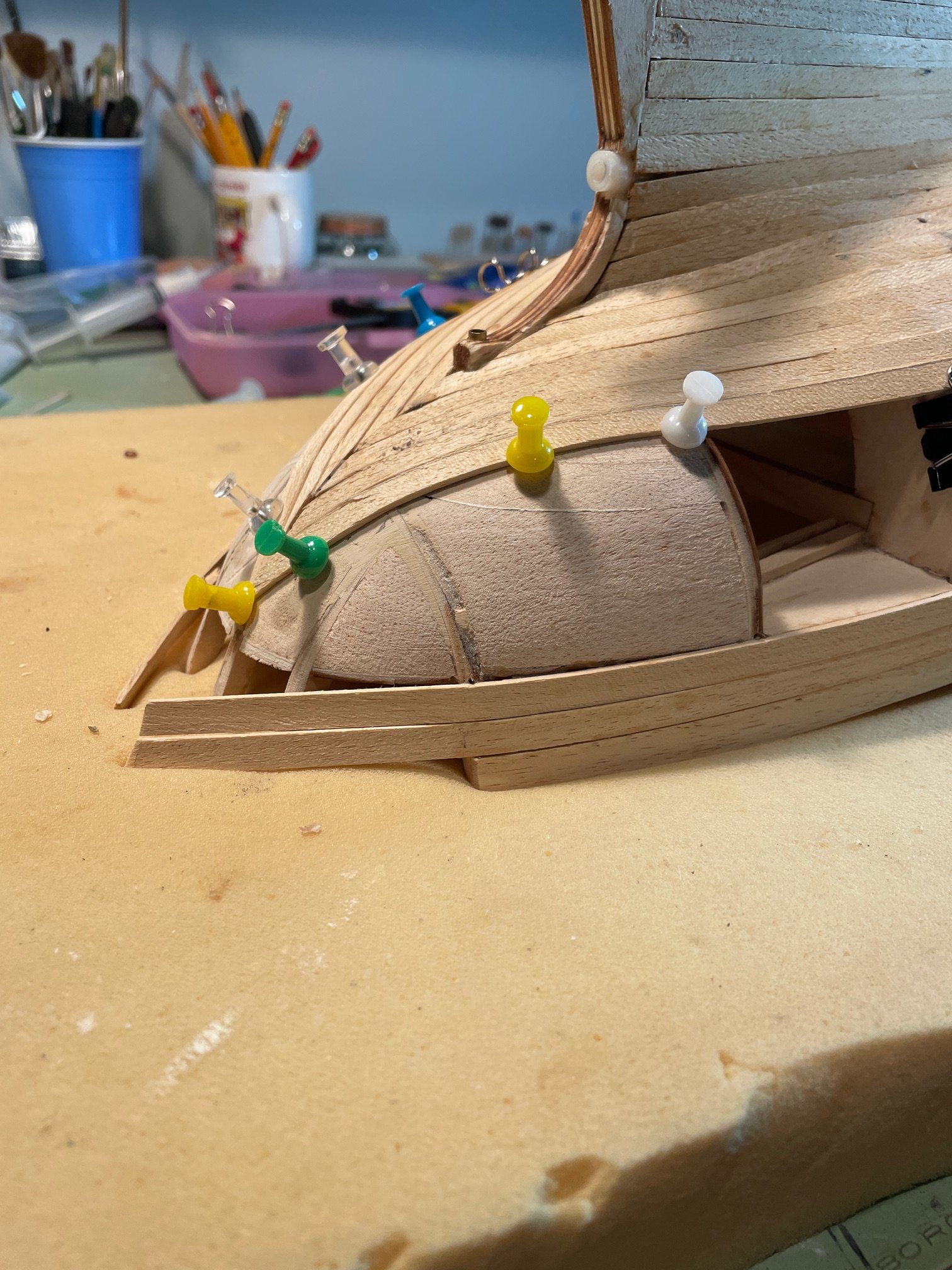
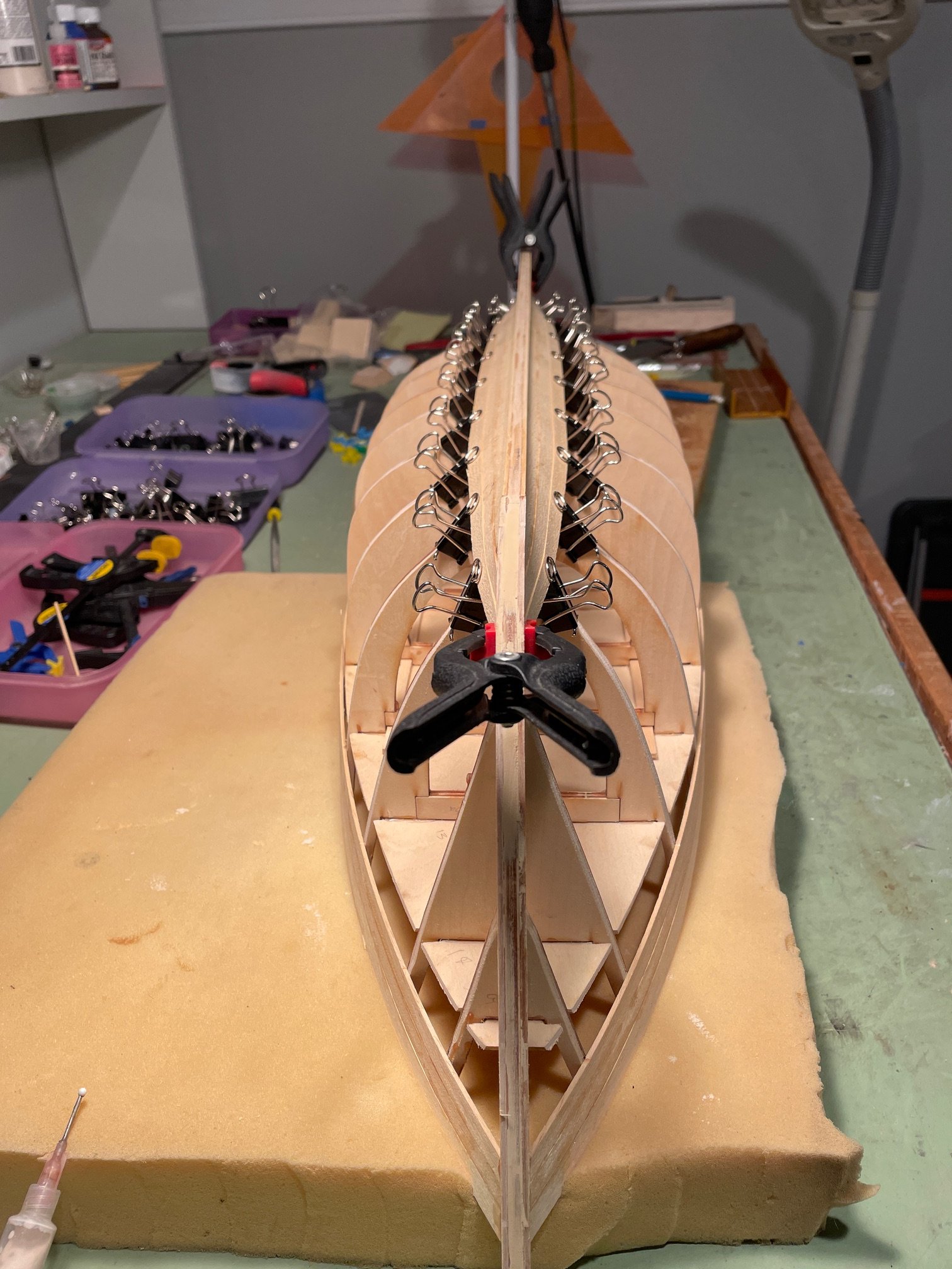
Planking the Hull
Just a quick update on progress. I’ve started planking the hull, beginning with the three planks above the deck line. The instructional diagram was a bit misleading—it suggests these three planks cover the entire hull area above the deck, but in reality, there's a large uncovered section at the bow.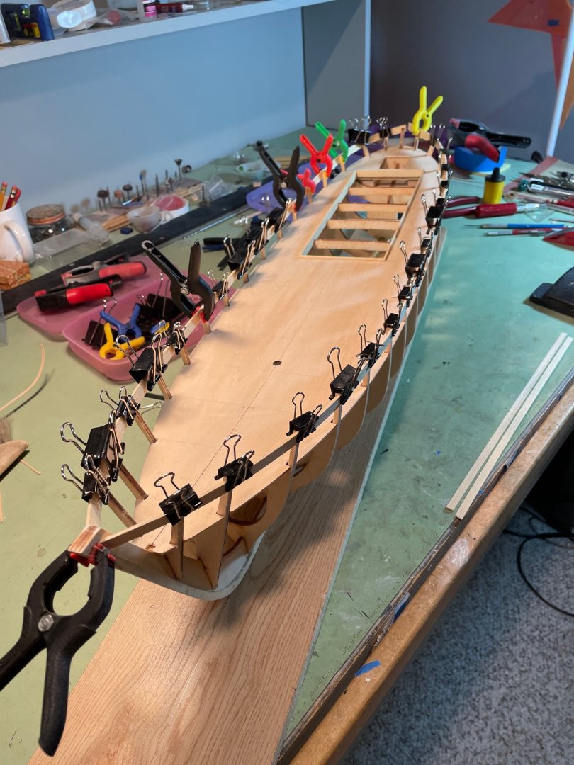

After that, I began planking from the keel upward. I’m treating the planking process much like I would on any plank-on-bulkhead (POB) model, though I'm not too concerned with the precise plank layout. Since the hull will eventually be sealed to make it watertight, the planking won’t be visible in the final build.

-
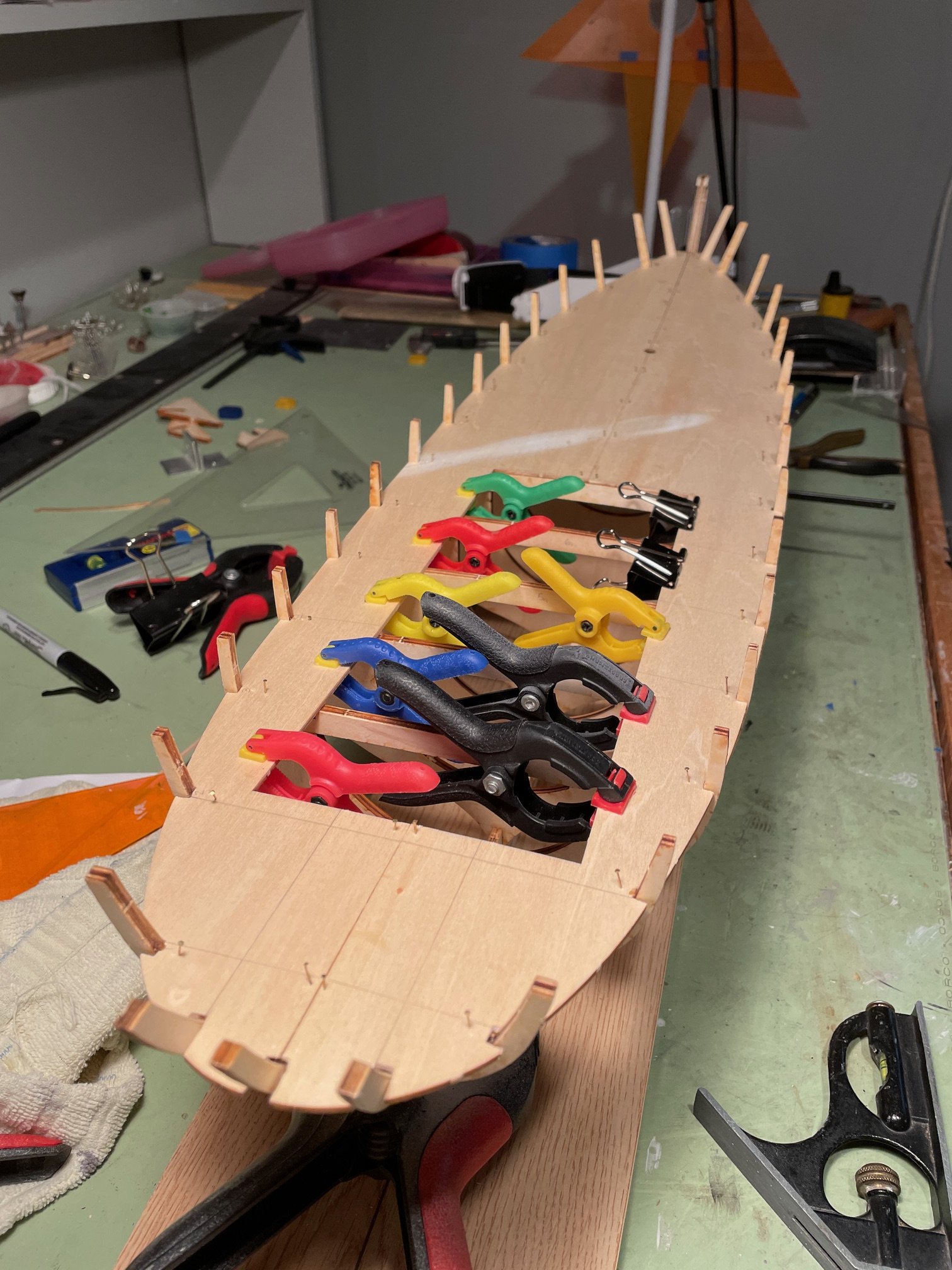
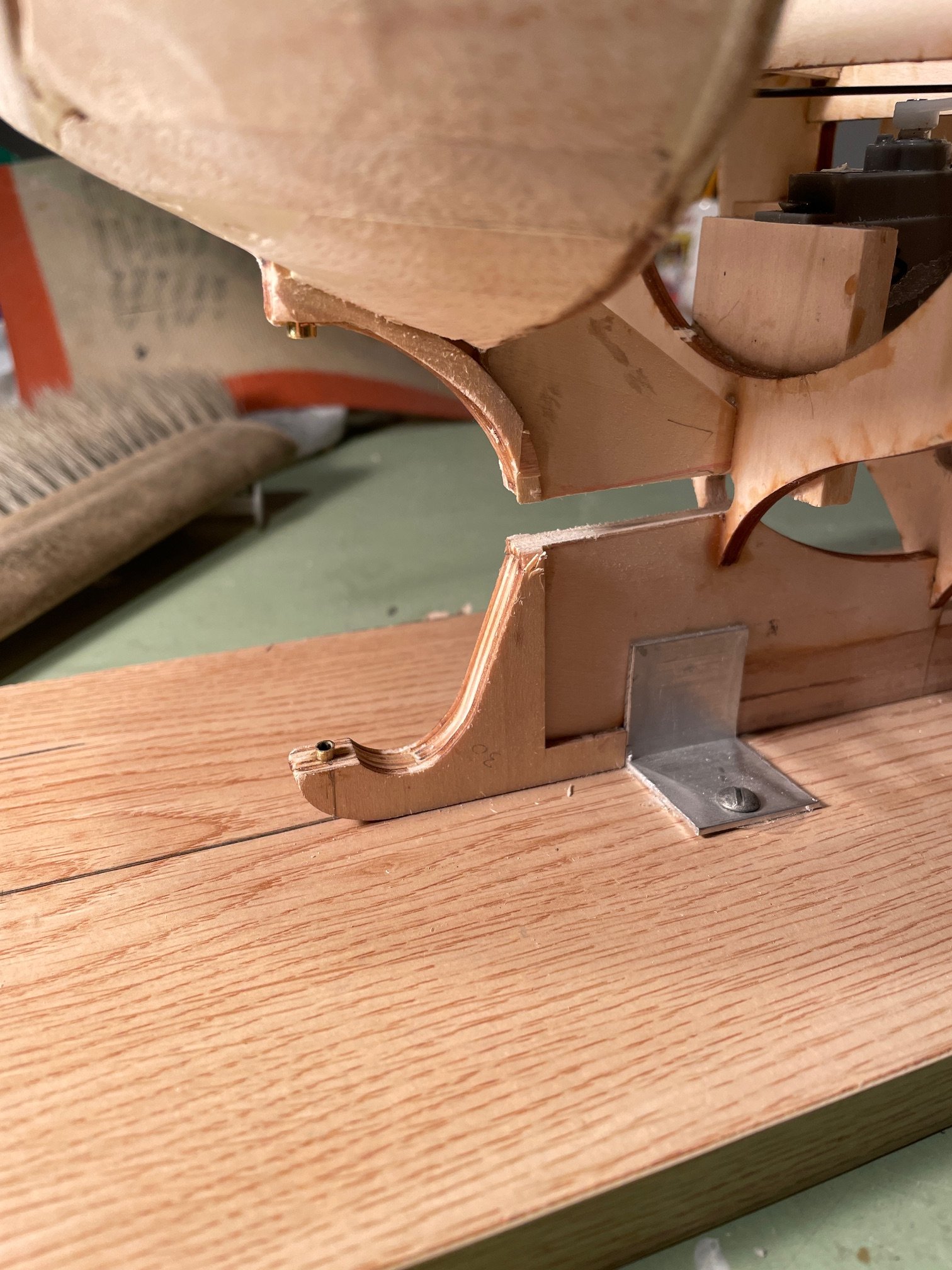
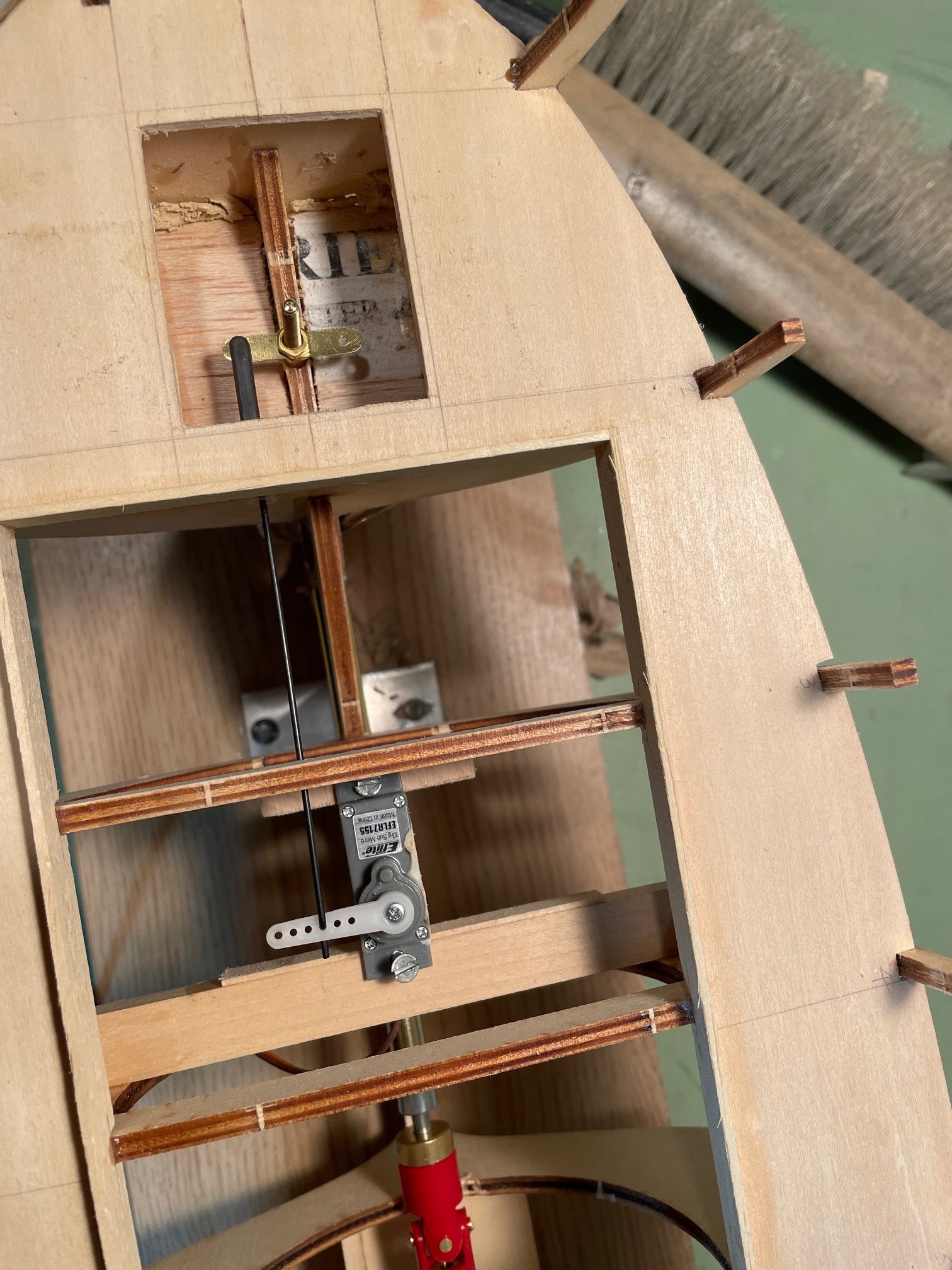
Deck, Tiller, and Drive Shaft
After the glue had fully dried on the bulkheads, I proceeded to glue the deck into place. To secure it, I used clamps around the access hatch and planking nails for the rest of the deck. I got the idea for using nails from @robdurant’s build log—thanks for the tip!

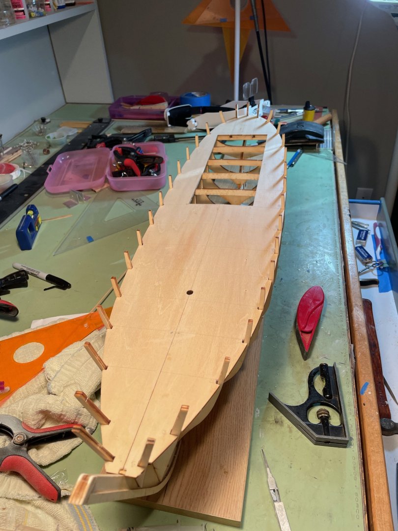
Once the glue set, I installed the pieces framing the access hatch. I assume these parts are designed to help position the cabin above the hatch. I also cut in the access hatch for the tiller.
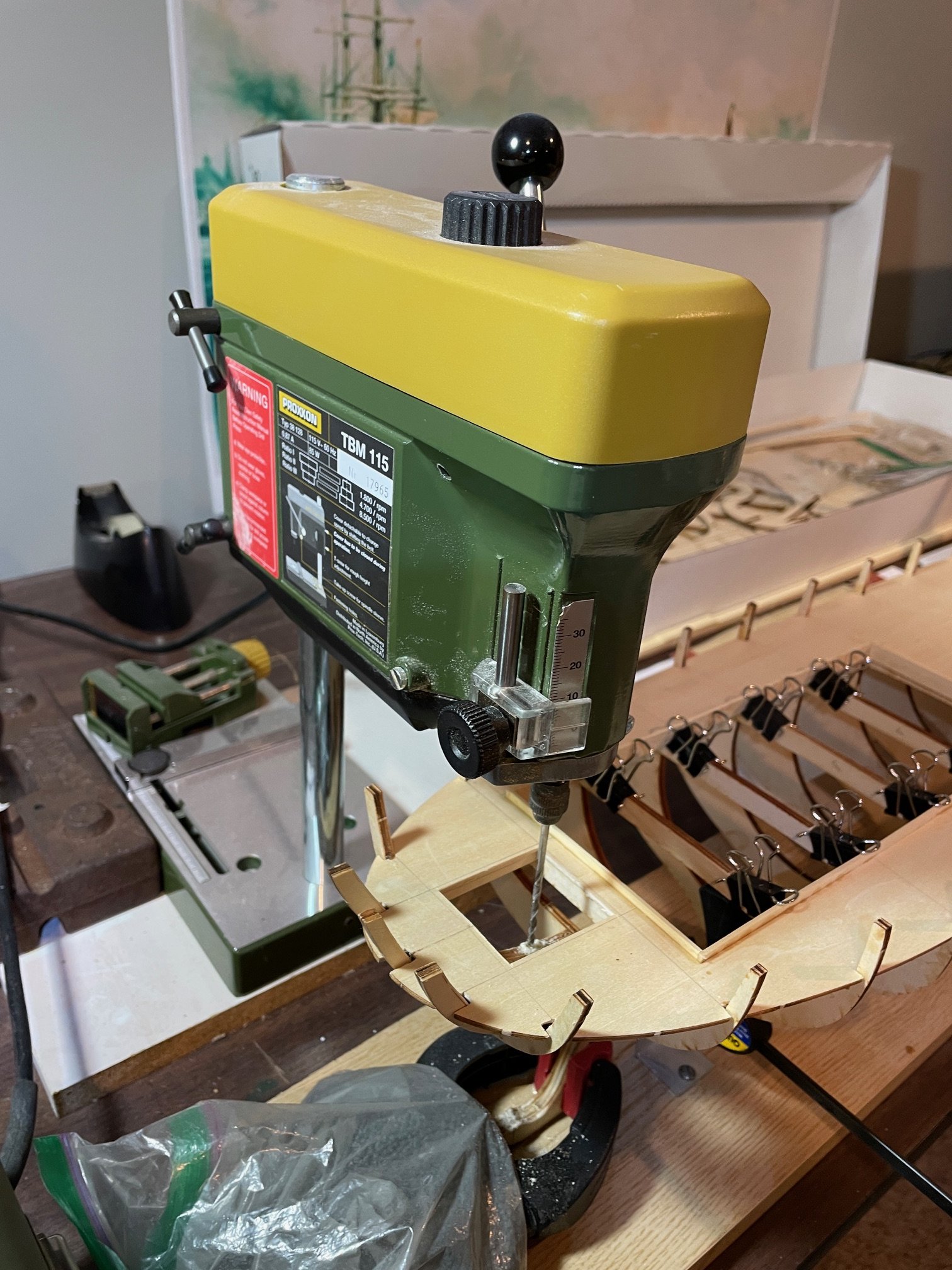
Next, I took a crack at drilling the hole in the keel frame for the tiller. It may have been a bit of overkill, but I used my mini drill press to ensure the hole was vertical and plumb.

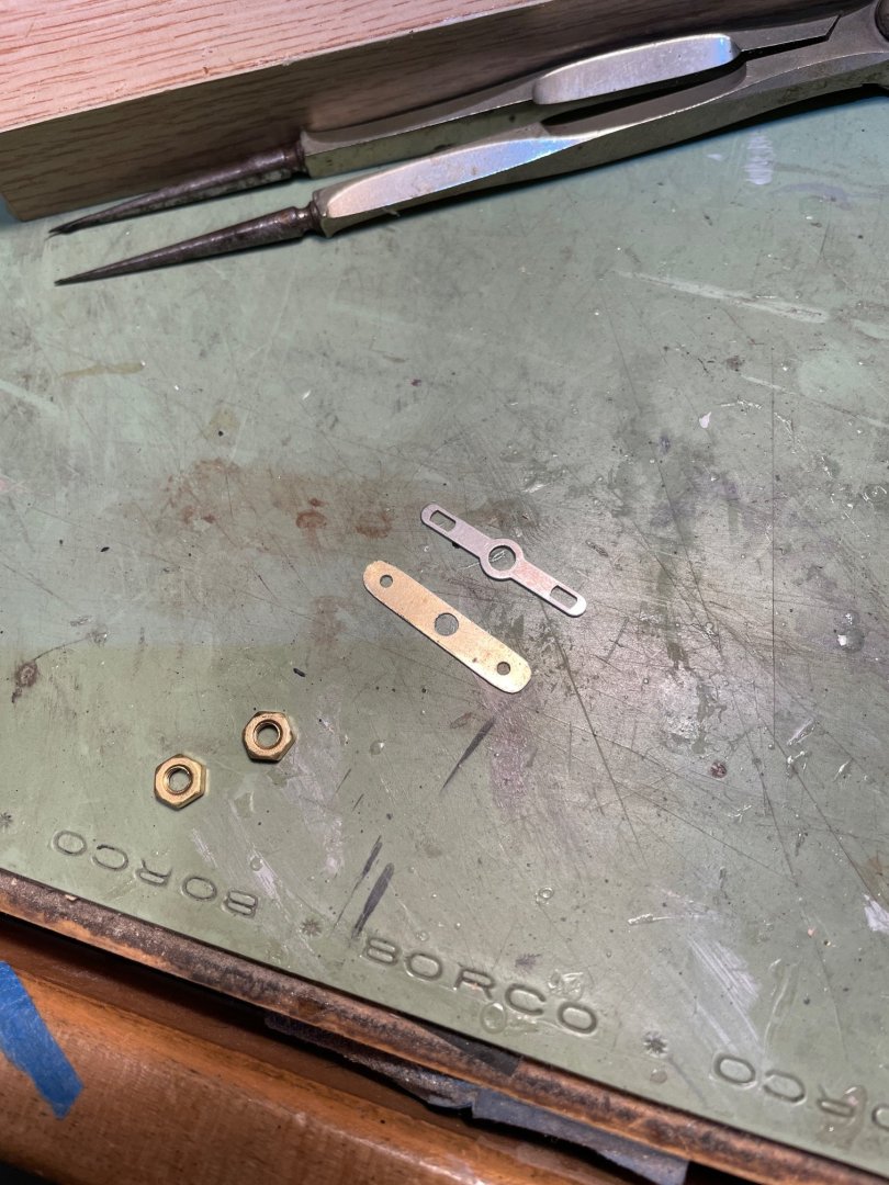
Now, one thing I’ve learned from Billing Boats is that they assume you know something about RC boats. They don’t provide any instructions on which parts to use for the tiller. After a bit of rummaging through the parts bag, I think I found the right pieces.
I wasn’t fond of the cross arm they provided due to the slotted holes—it just seemed like there’d be too much slop in the movement. So, I decided to make my own.
After that, I carefully cut out the keel for the propeller shaft. This part was a little nerve-wracking since it was the first time I'd had to cut the keel apart in one of my builds, but it all went smoothly.
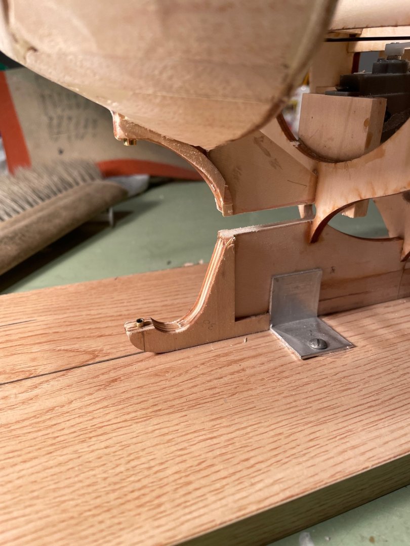
With everything cut and fitted, the shaft and tiller fit very well. Cutting the stuffing tube and shaft to the right length was pretty straight forward.
I also installed the tiller servo and temporarily set the motor in place to check for fit.

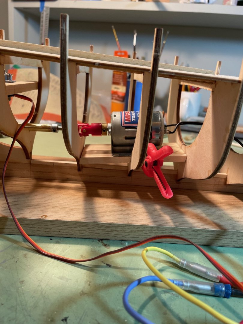
I wanted to do all of this before planking the hull, as I thought it would give me better control over getting the propeller shaft to fit correctly and ensure the motor was in the right spot. I did a test run and everything worked well.
Thanks for all the likes.
- king derelict, yvesvidal, rcweir and 2 others
-
5
-
-
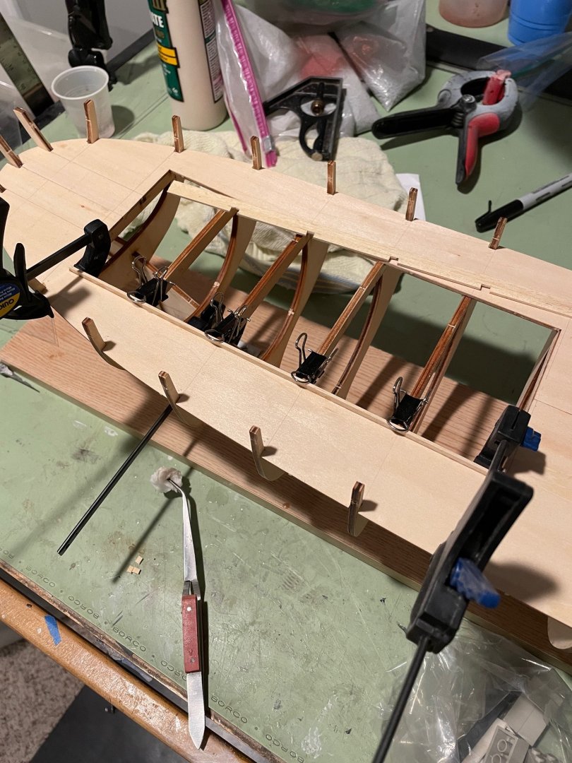
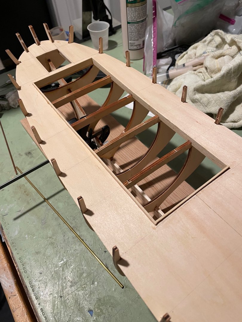
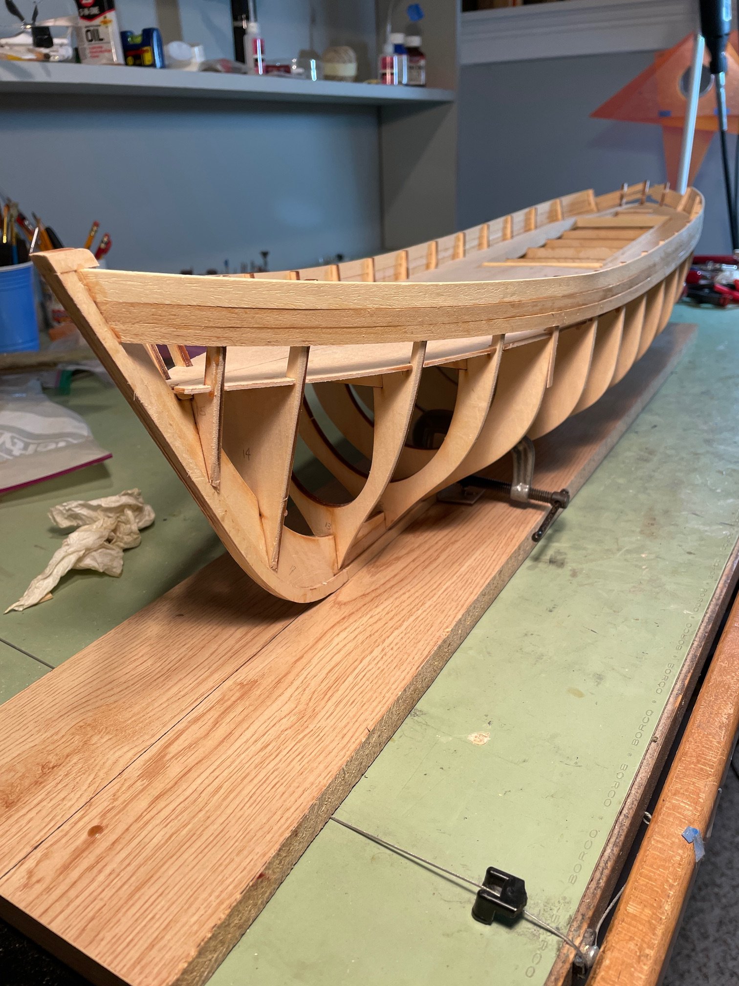
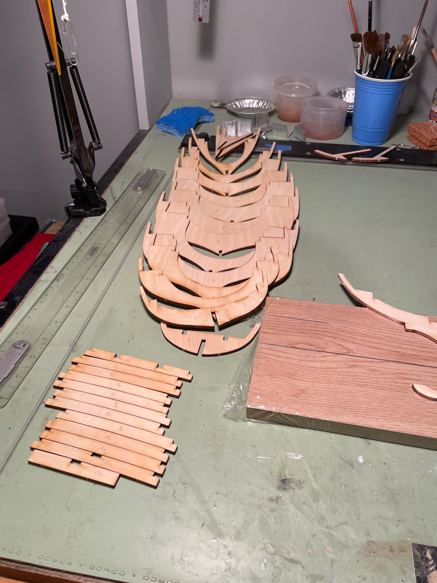
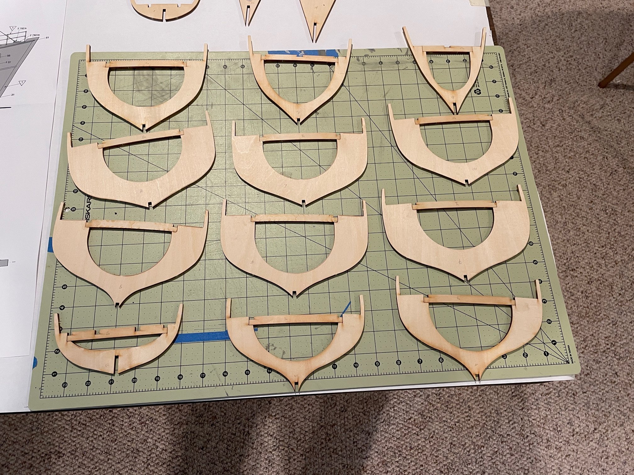
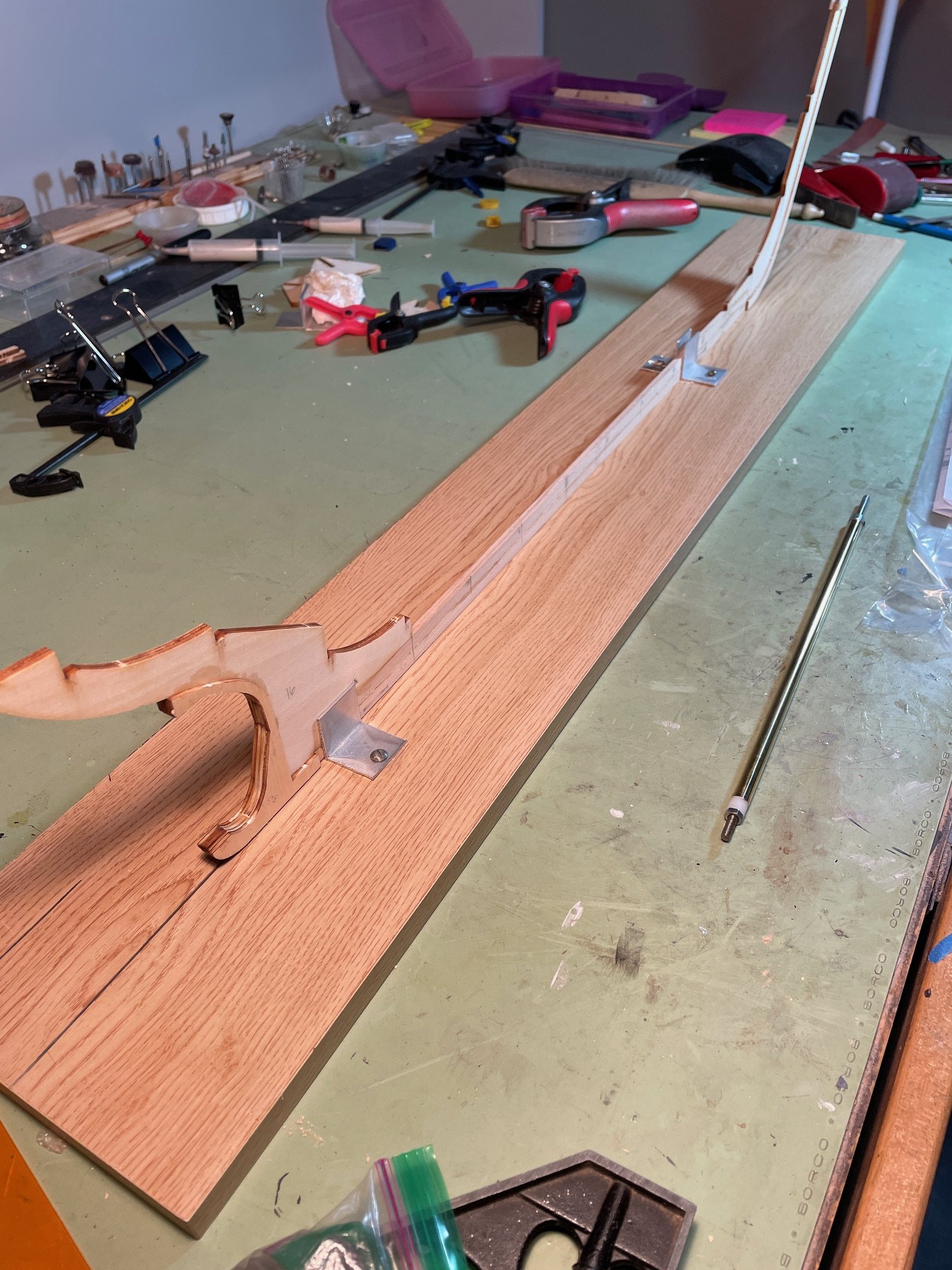
Bulkhead Frames
All the bulkhead frames and cross pieces were removed from the wooden sheets.

At this point, I deviated from the instructions by gluing the cross pieces to the bulkheads before installing the bulkheads onto the keel.

To help keep the keel straight and vertical during assembly, I built a support jig using aluminum angle pieces.

After reading numerous Nordkap build logs, I noticed a common issue: those who followed the dimensions provided in the instructions often struggled with bulkhead alignment at the deck level. To avoid this problem, I used the deck itself as a template when installing the bulkheads. This ensured proper spacing and alignment.
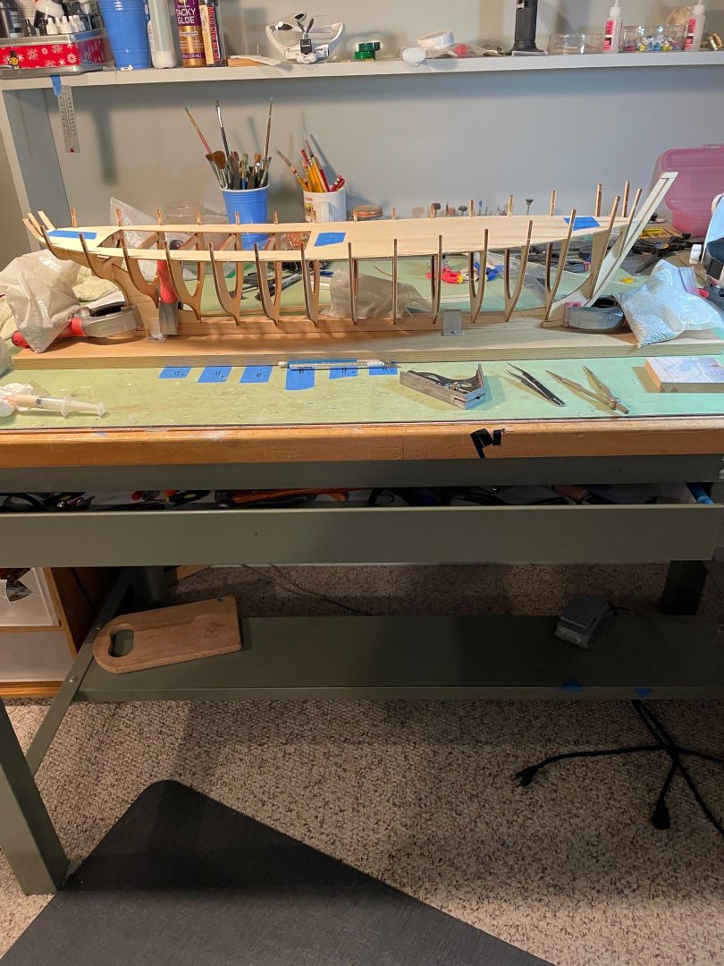
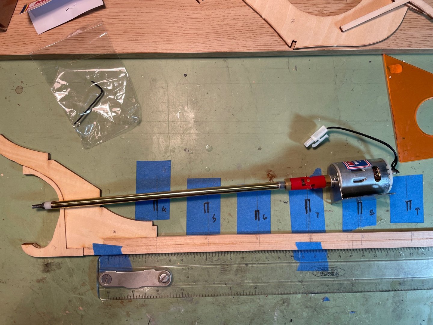
Once the bulkheads were in place, I found an answer to my earlier question about motor placement. The access cutout in the deck only extends as far back as bulkhead #7. Placing the motor at bulkhead #8 would make it inaccessible, so this confirmed that the motor needs to be positioned near the #6 bulkhead.

And thank you for all the likes.
- king derelict, rcweir, robdurant and 1 other
-
4
-
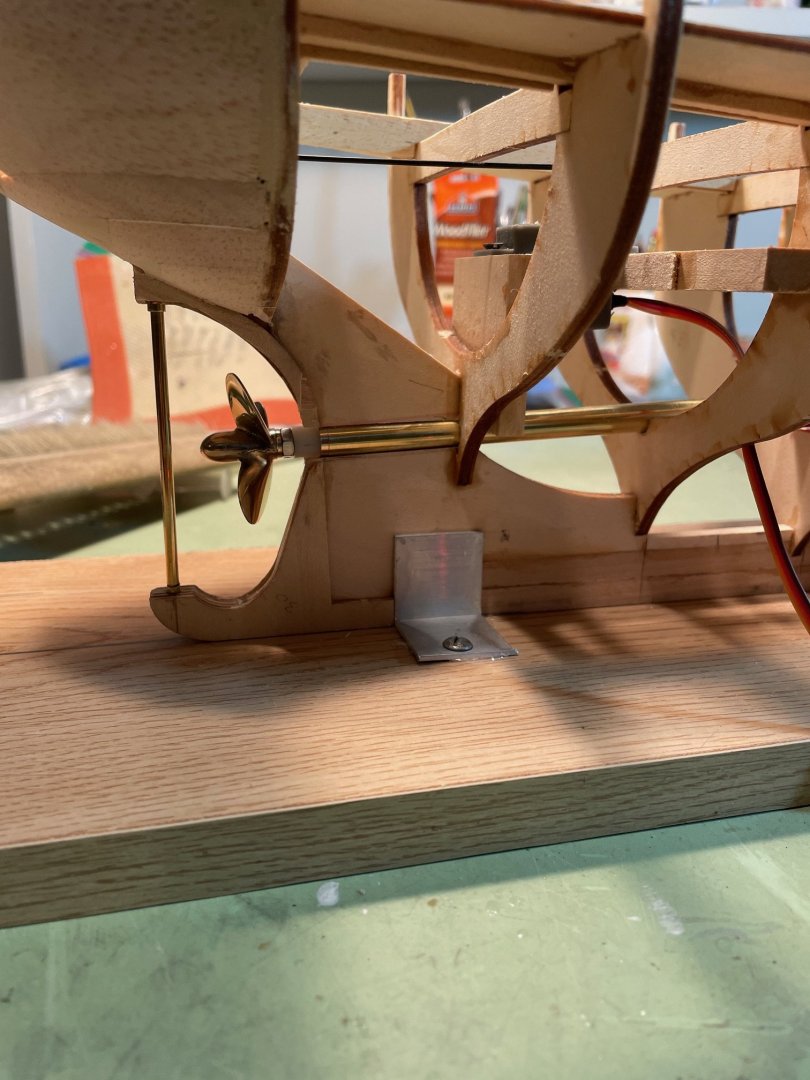
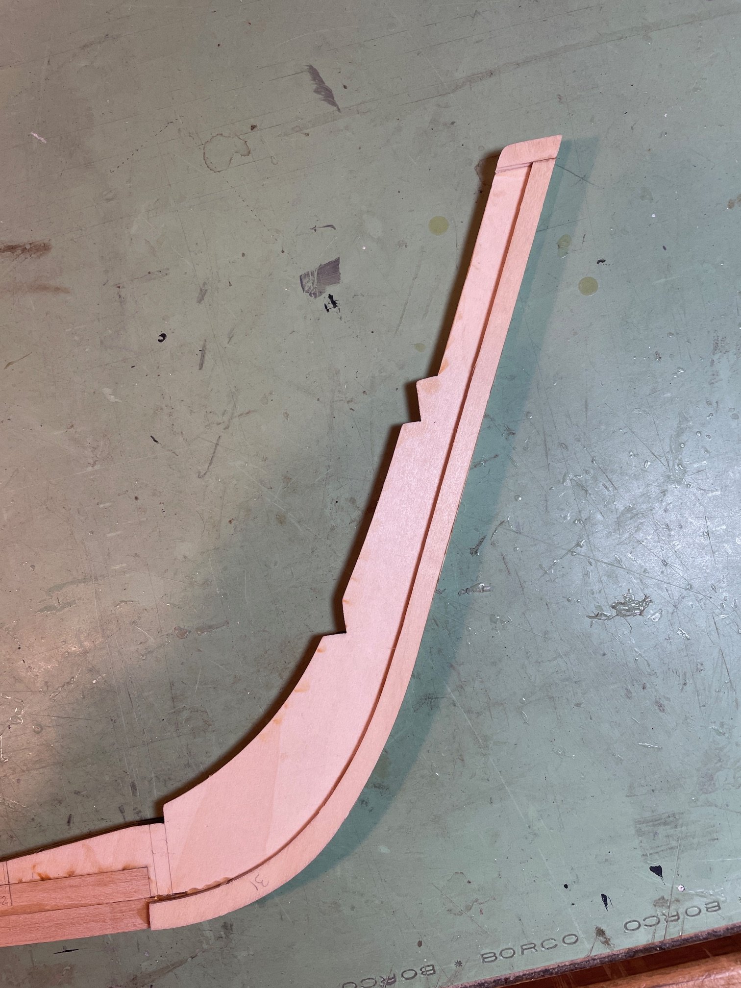
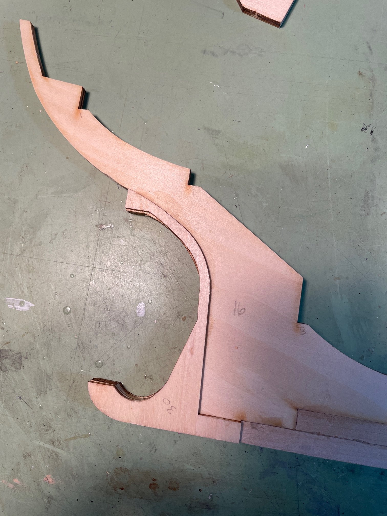
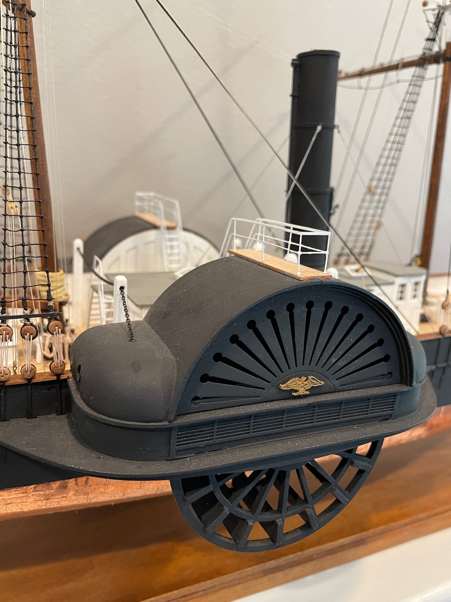
Stem, Stern, and Keel Construction
I began by gluing the two keel strips to the stem and stern post assemblies.
Once the glue had fully dried, I added the additional pieces to both the stern and stem. I believe these form the rabbet for the planking. A quick note: the instructional diagram show two small parts (#31) meant to be attached to the top of the stem. I may have missed them—old eyes—but I couldn’t find these parts on any of the sheets. So, I simply fabricated them using leftover material from the sheet the other parts came from.


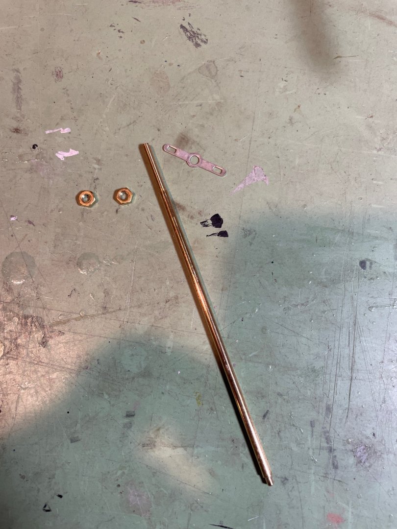
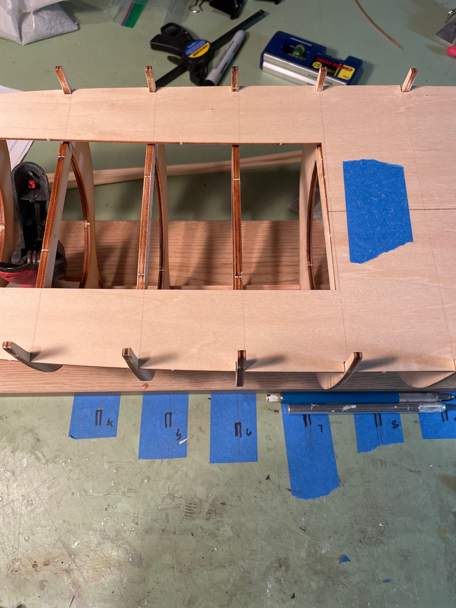
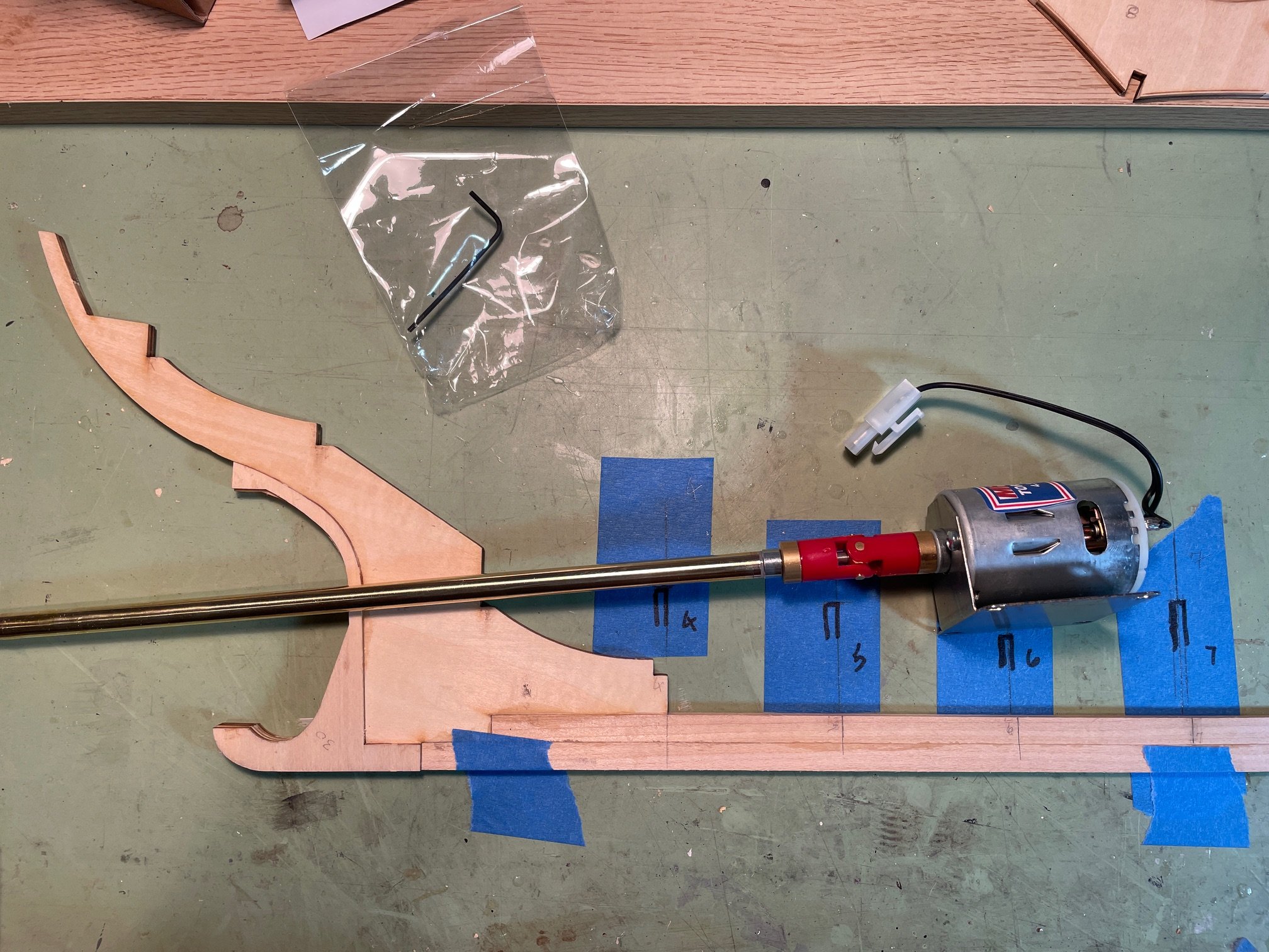
Now that the keel is laid, I decided to do some preliminary planning for the propeller shaft and motor layout. The stuffing tube is 8 mm in diameter and approximately 9 inches long, though it can be cut to any length as needed.
Initially, I was planning to shorten the shaft to about 5 inches, which would position the motor just above the #6 bulkhead. This configuration is shown in the first photo below. The black marks on the tape indicate the top edge of the bulkheads at the ship’s centerline.
However, I’m now considering using the full 9-inch shaft without cutting it. In that case, the motor would sit above the #8 bulkhead, as shown in the second photo. The only concern I have with the longer shaft is the potential for increased vibration.
I’d appreciate any advice or suggestions on which setup might be better—especially in terms of stability, performance, and vibration. Or if there's another option I should consider. Thanks and thanks for the likes.

- yvesvidal, king derelict, robdurant and 1 other
-
4
-
@yvesvidal welcome aboard and thanks for following.
@robdurant welcome and thank you for all your help.
Quick Update:
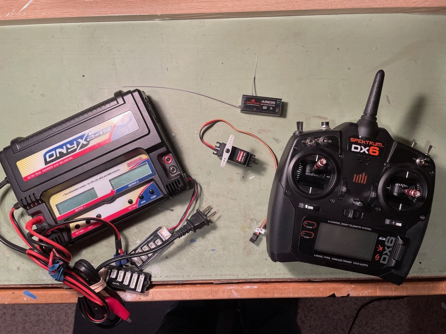
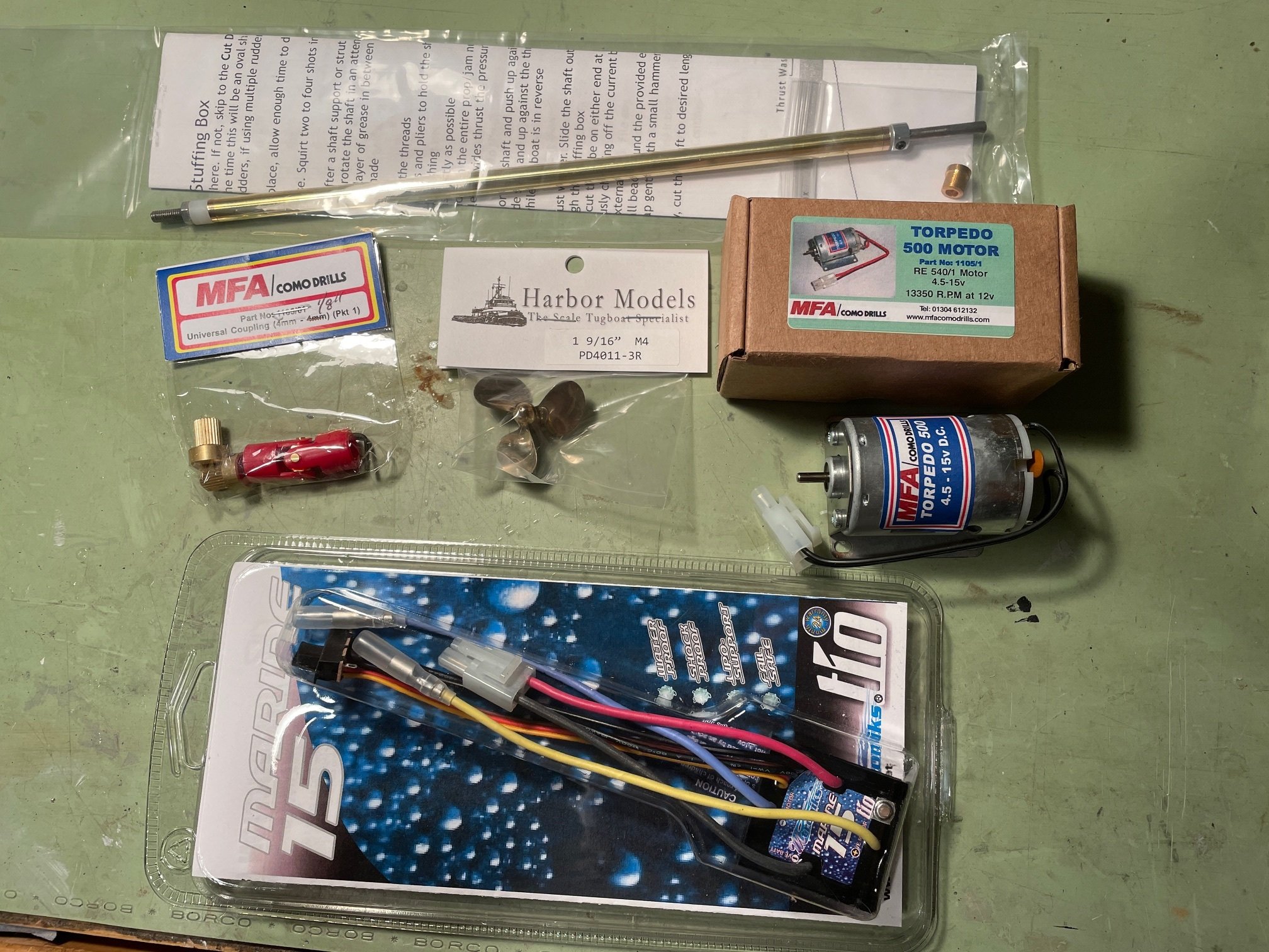
No major progress on the ship build yet, but I did receive some key parts to begin motorizing the model. I picked up a 40mm 3-blade brass prop, a Torpedo motor with mount, a 4mm shaft and stuffing tube, a universal joint coupler, and a 15-amp ESC — all from Harbor Models. Big thanks to Nick, the owner, who was very helpful.

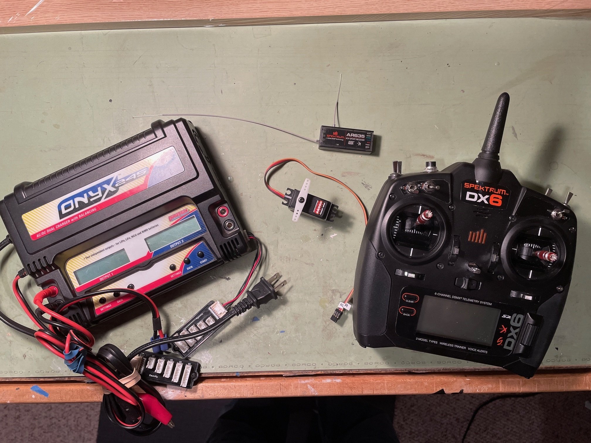
I also got some great gear from my brother (mentioned in the first post), including a Spektrum DX6 transmitter, Spektrum AR635 receiver, Spektrum A6000 servo, and a battery charger. All I need now is a battery, and I’ll be ready to start testing things out.
Just a reminder — this is my first R/C boat model, so I’m still learning the ropes. Any tips, advice, or constructive criticism would be greatly appreciated!
- king derelict, yvesvidal and robdurant
-
3
-
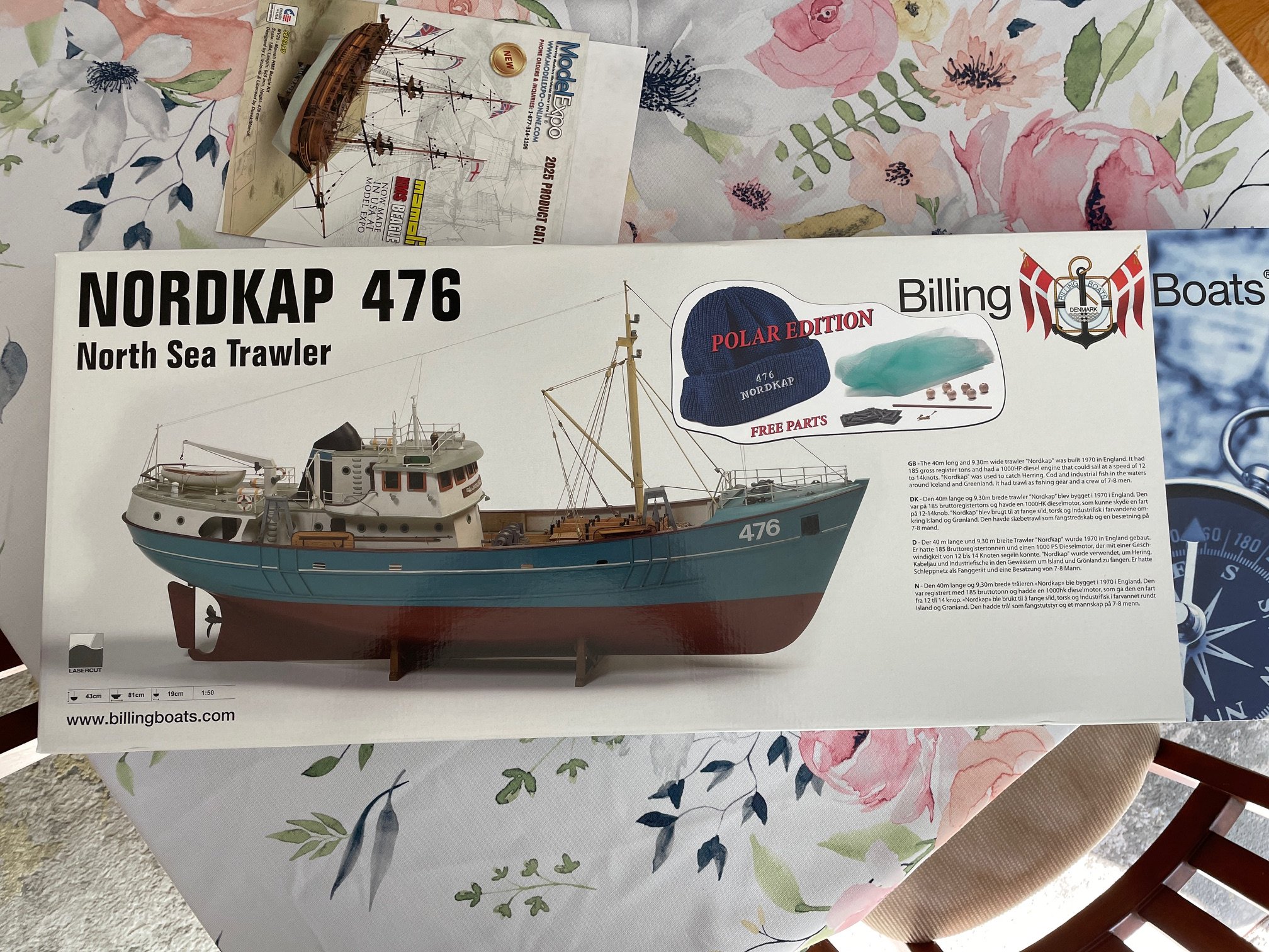
Hello everyone,
Welcome to my new build log for the Nordkap 476 by Billing Boats. I chose this model as my first venture into remote-controlled ships; something I’ve wanted to try for a while. My only previous R/C experience is with an electric plane I built for my brother a few years ago, so this will be my first foray into R/C boating.
I’ve been fortunate to connect with 'robdurant', who has a detailed Nordkap build log here on MSW. He’s been incredibly helpful in guiding me through the process and pointing out the key components needed to fully motorize the vessel.
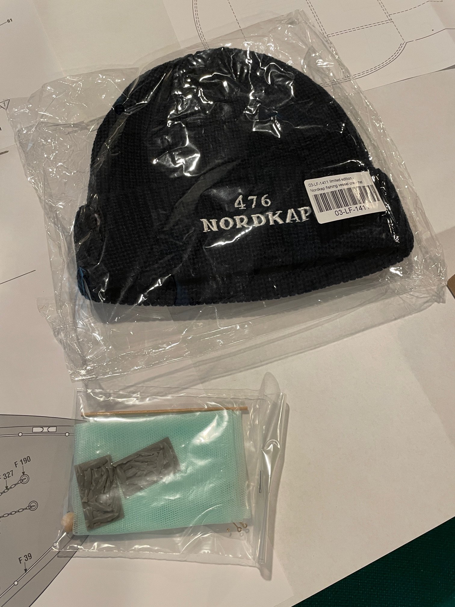
A few particulars: Built In 1970 in England, Tonnage 185 gross register tonnage, Length overall 40.0 m, Beam 9.30 m, Motor 1000 HP diesel, Engine speed 12-14 knots, Crew 7-8 men, Fishing tackle Drag net (trawl), Fishing area Around Iceland and Greenland, Haul Herrings, cod and trash fish.
Length of model 81.5 cm (32"), Beam of model 19.5 cm (7.68"), Height of model 43.0 cm (17")
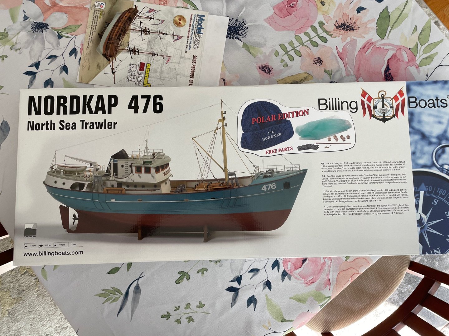
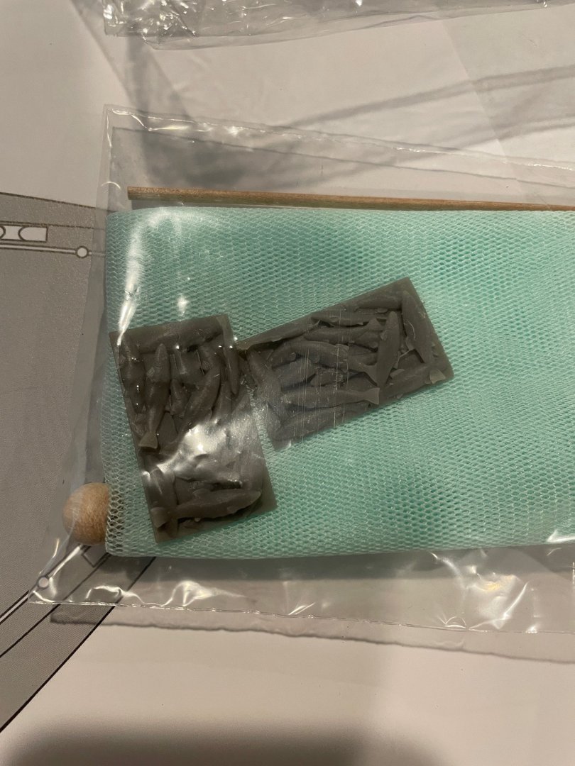
I guess I was fortunate, because unbeknownst to me when I ordered the kit, it came with a cap and some free extras—a fishing net and even some fish!!

Looking forward to sharing this journey with you all!
- ccoyle, robdurant, king derelict and 2 others
-
5
-
Hi everyone,
I’ve just received the Billing Boats Nordkap 476 and I’m really excited to get started. Before I begin however, I’d like to plan ahead and get a better understanding of what’s involved in motorizing it for remote control—as this will affect how I approach certain parts of the construction.
I’m relatively new to RC setups and would really appreciate some guidance on what components are needed to make the Nordkap fully operable via remote control. Specifically, I’d like to know:
• What type of motor would be suitable for this size/model
• A compatible ESC (electronic speed controller) - reversible?
• What kind of battery (type, voltage, capacity) would be appropriate
• Recommendations for a transmitter/receiver combo
• What servo to use for the rudder
• I’m also looking to replace the stock propeller and propeller shaft that came with the kit—any advice on aftermarket options that would offer better performance and durability would be great. I've read robdurant’s build log for the Nordkap and really like the propeller and shaft he got from George Sitek, but they are somewhere in the UK and it would cost me roughly $50.00 for the propeller and shaft, which seems a little excessive (maybe not).• Any other essentials like motor mounts and universal couplings, or even sound modules (not essential, but interesting to consider).
The model when finished will be roughly 32" in length x 8" beam x 17" in height.
Any advice or links where to purchase the above parts would be incredibly helpful. I’d love to go into this build with a solid plan.
Thanks in advance for your help!
-
-
-
-
-
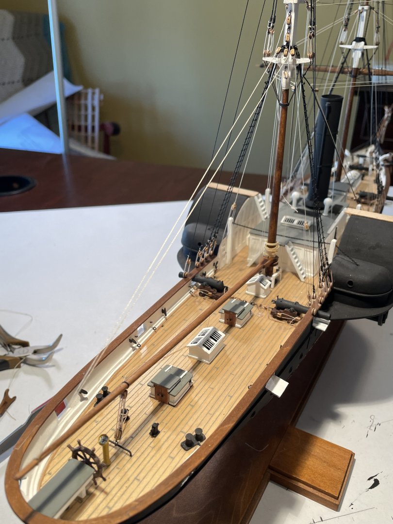
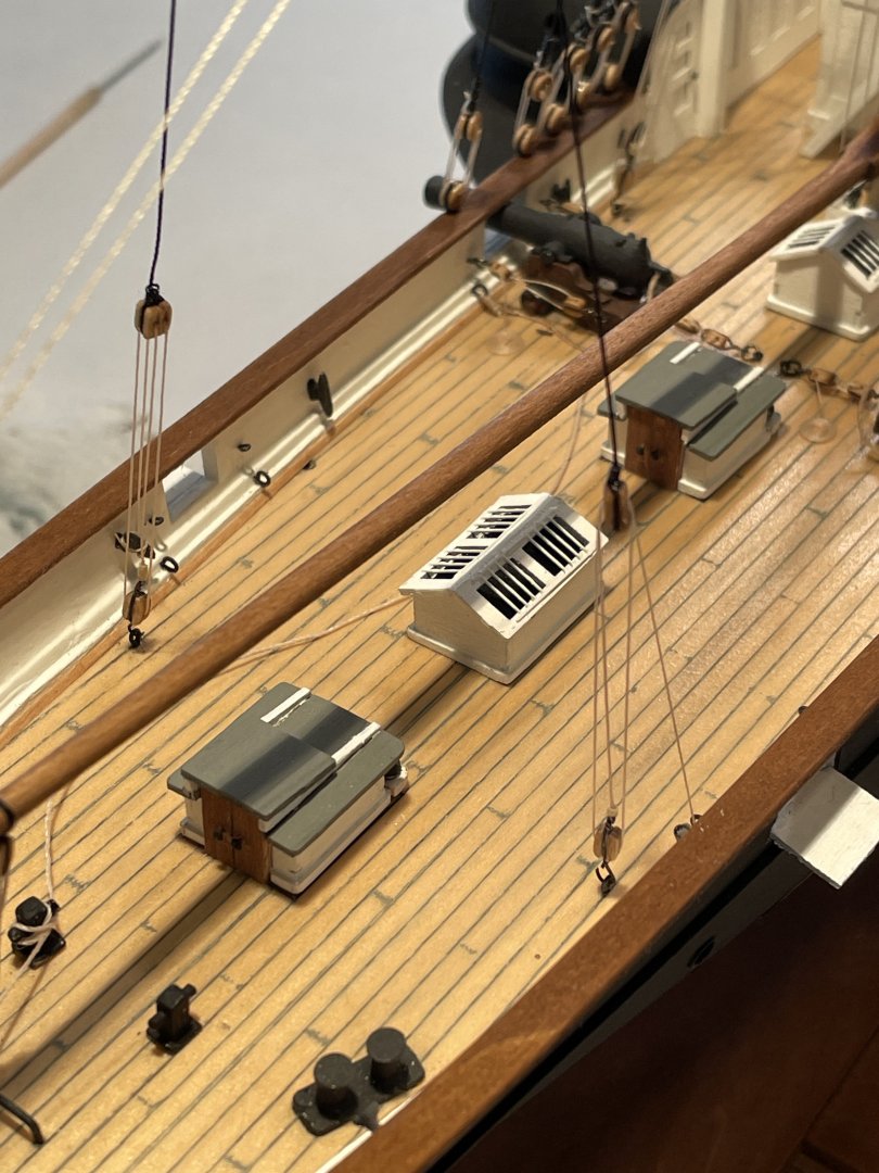
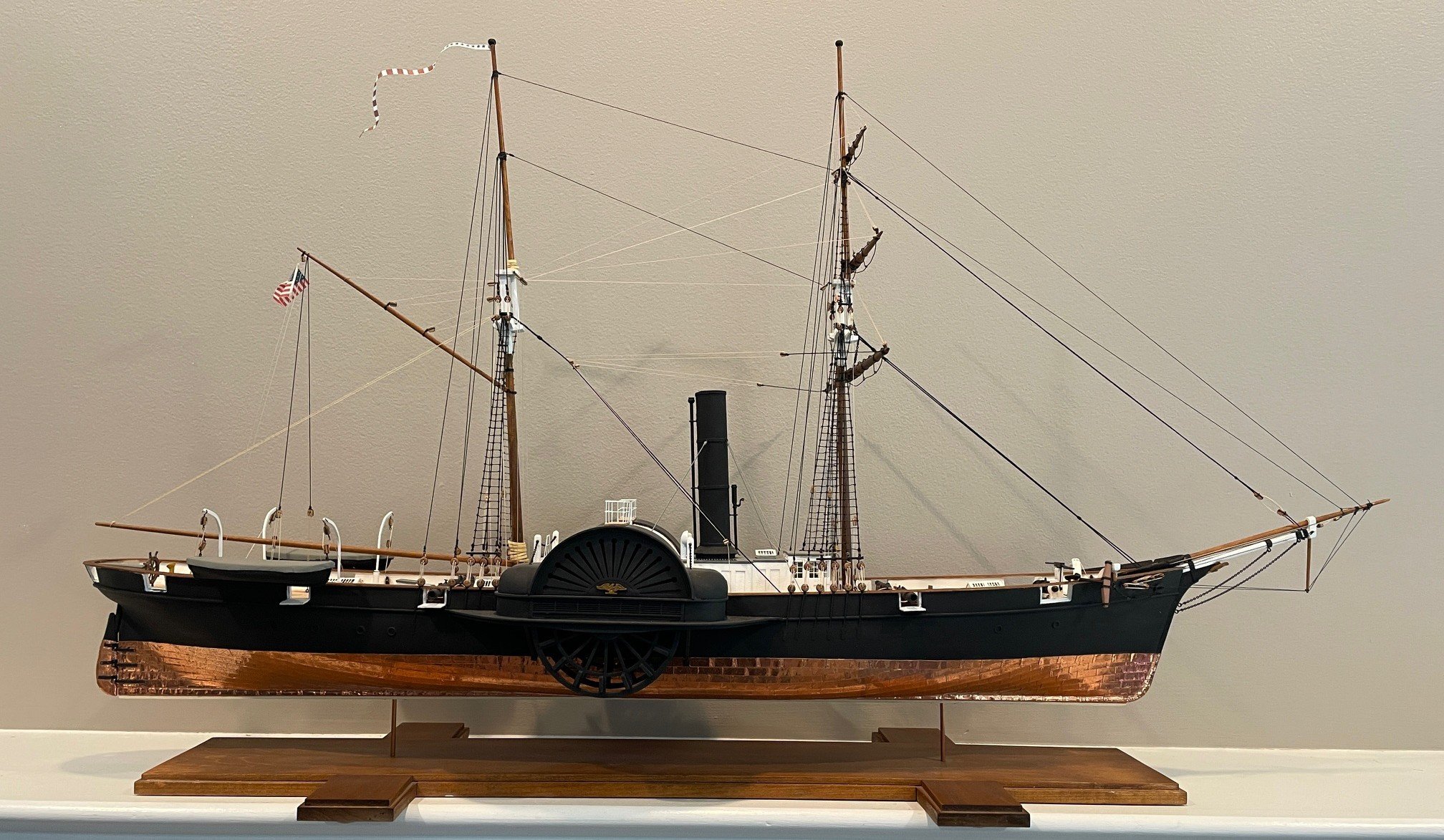
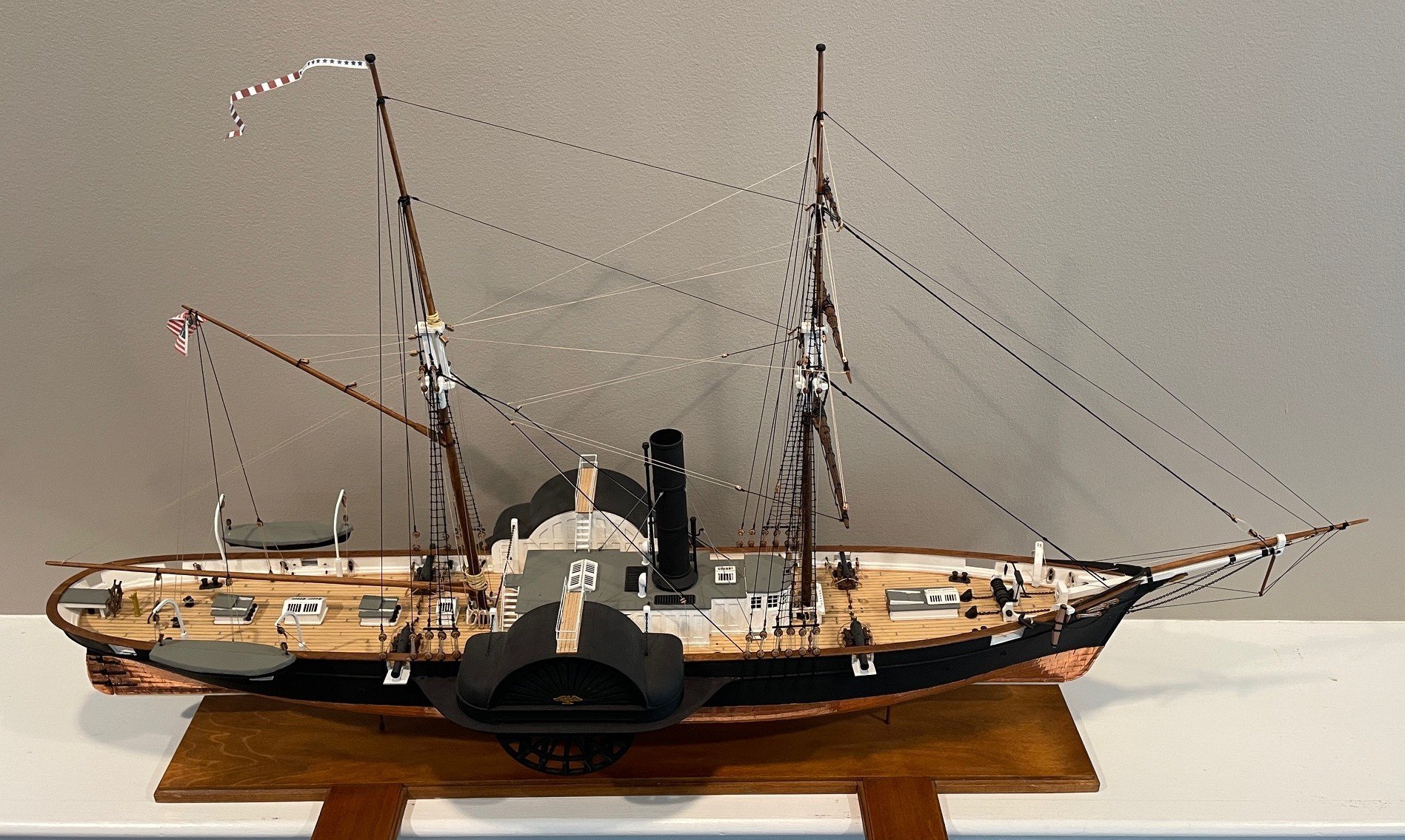
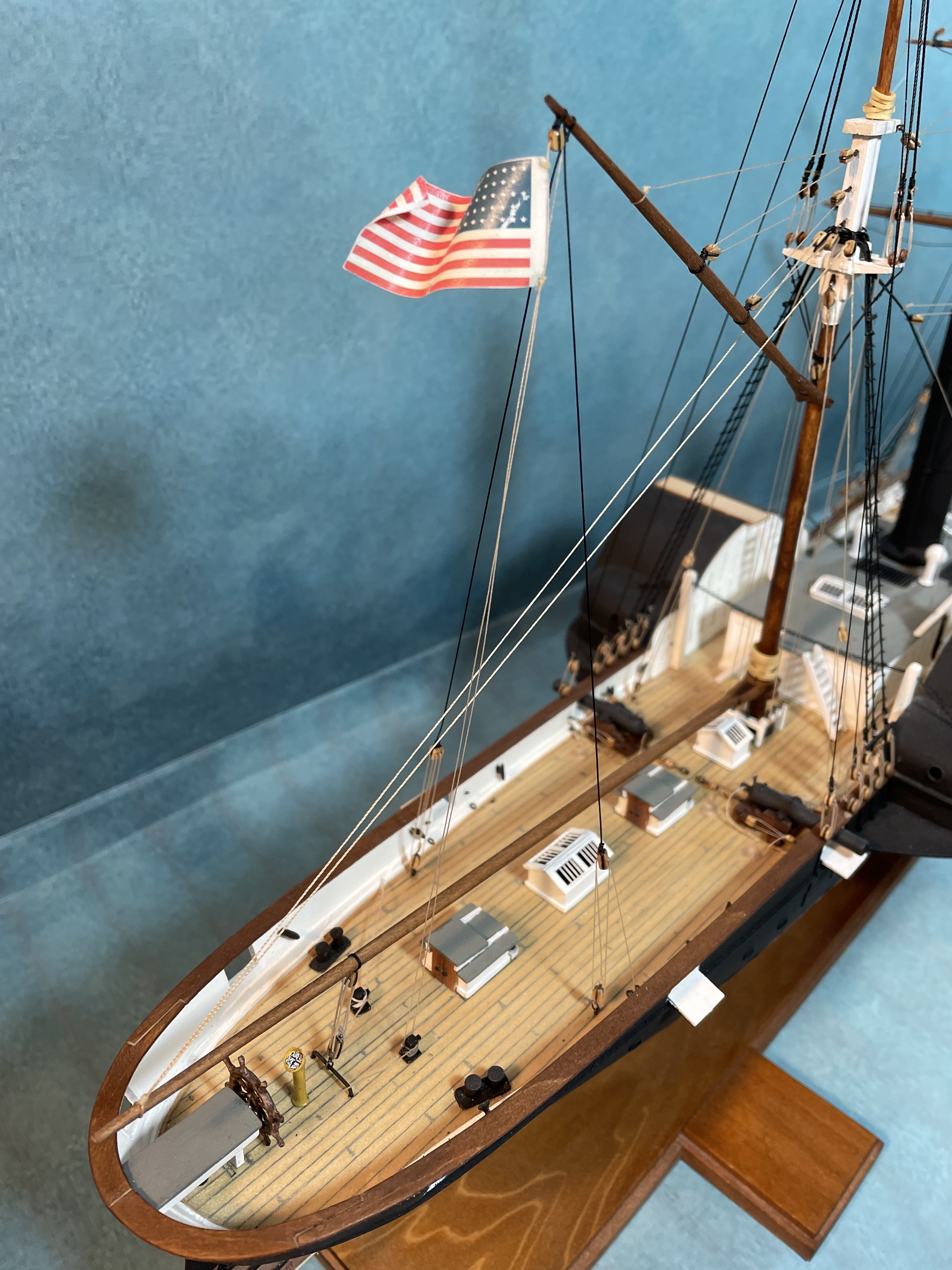
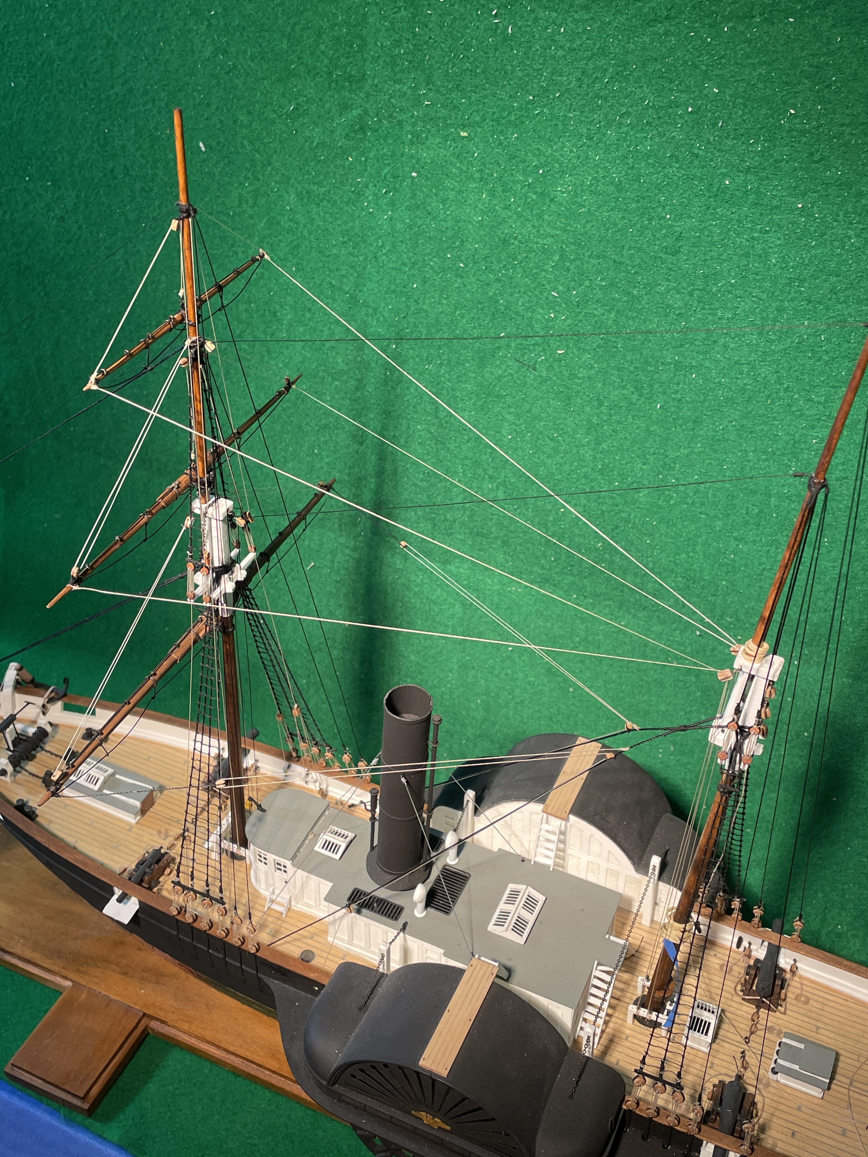
A few odds and ends and I’m FINISHED!
Railings
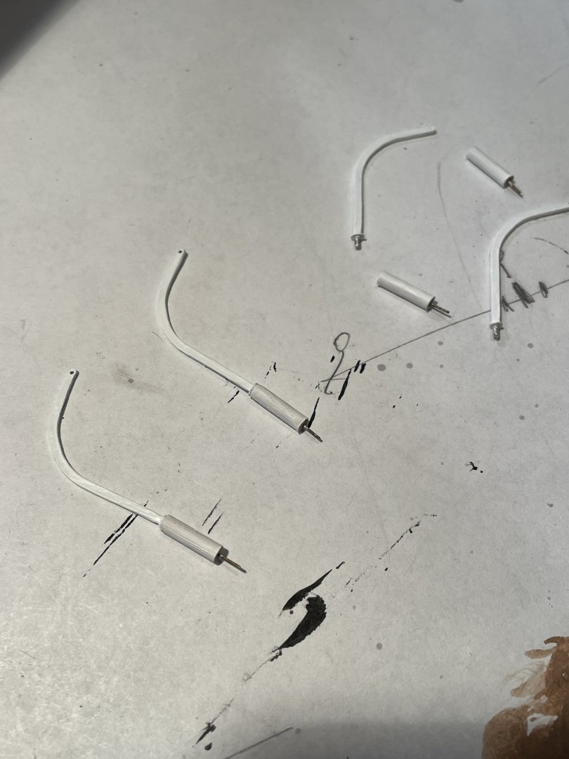
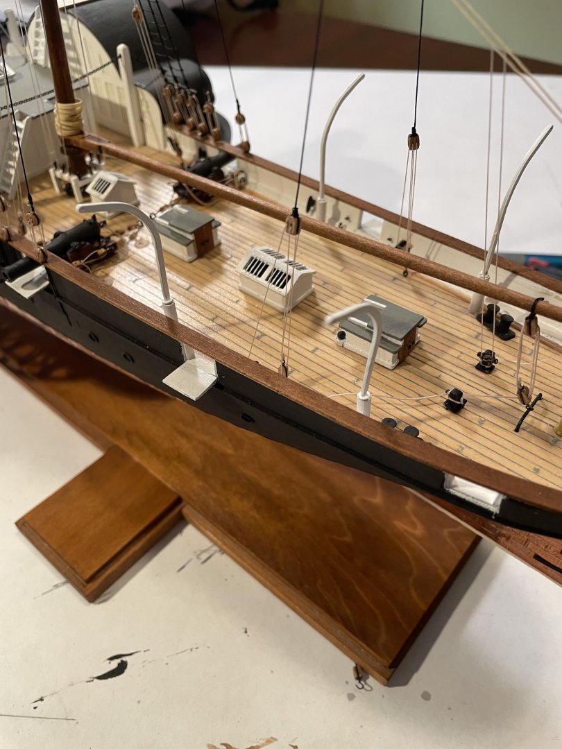
The PE hand railings were bent as required and then painted white. Installation took some finagling but eventually all the posts went into place.

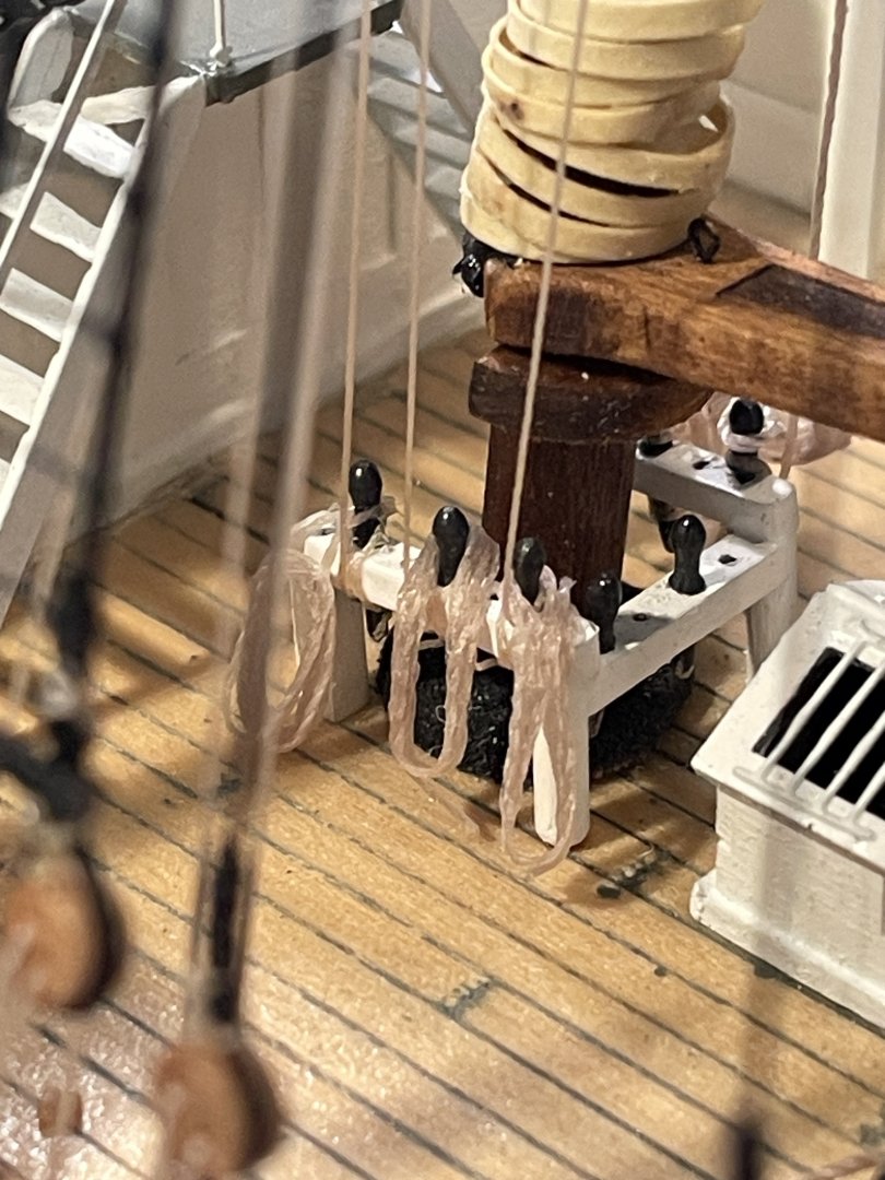
Then my least favorite thing to make, rope coils. Most came out alright but I wish someone would sell pre-made rope coils. I would definitely buy them.
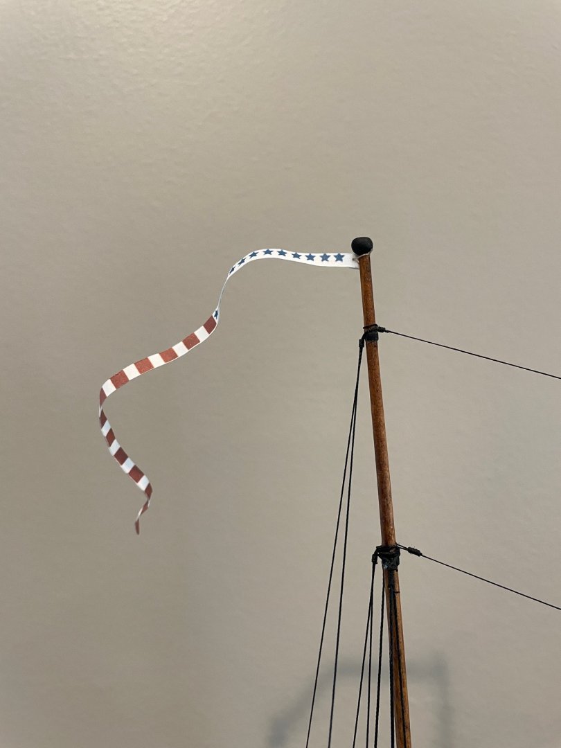
Lastly I decided to add a pendant to the main mast similar to the one shown in the first picture in my post #29. I scaled the pendant from the picture and then drew and printed it out.

I pasted two of the sides together and then gave it a few curls.
Completed ship.
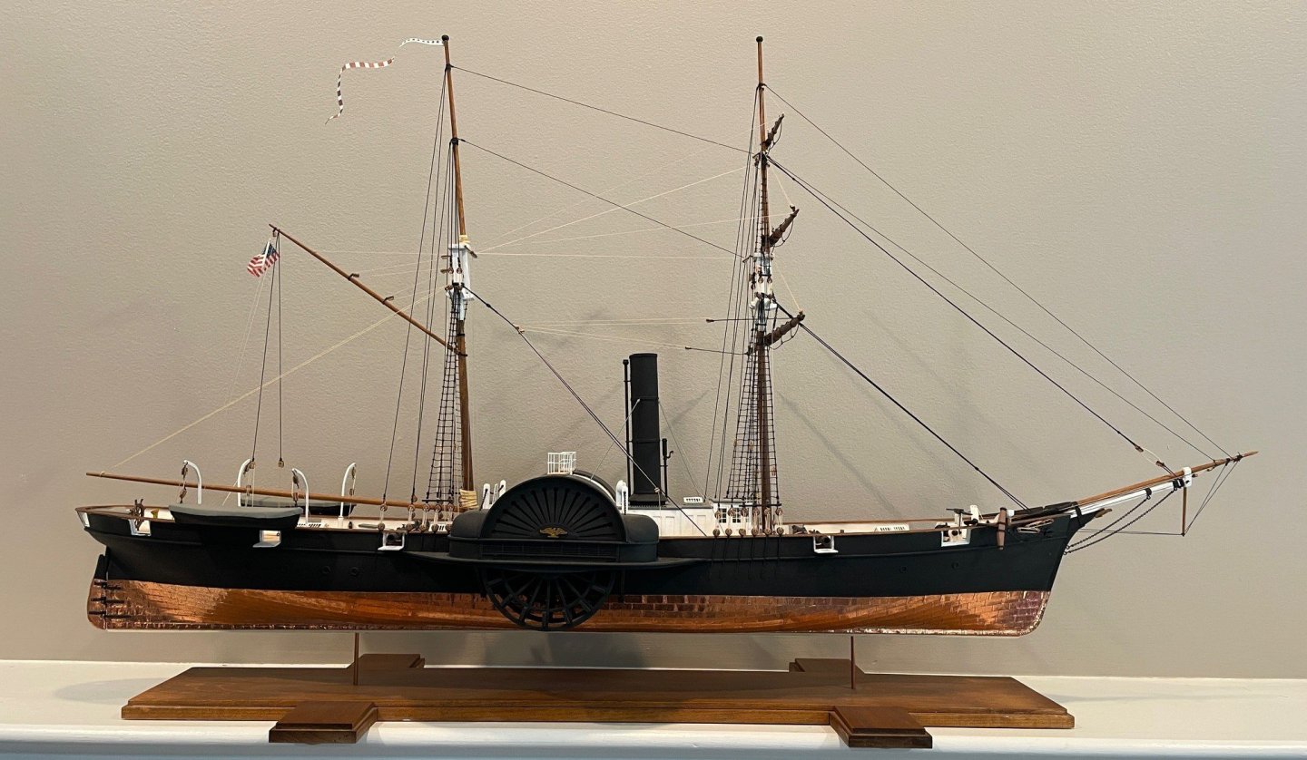

I enjoyed making this ship, the instructions were clear and the included materials were satisfactory for the most part. My only complaint is that the rigging thread that is provided could have been a little better quality. All in all though it’s a good kit and I would recommend it if you’re looking to do a ship with side paddle wheels.
-
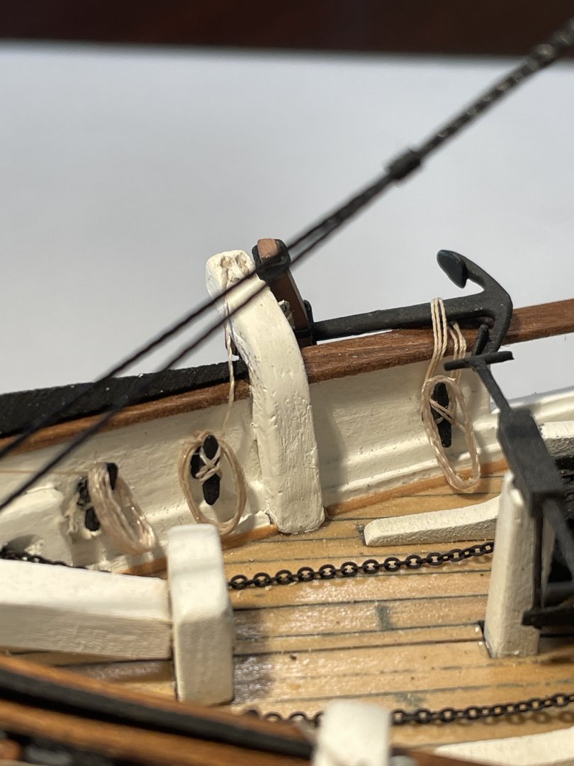
Ensign halliard & Ensign
The ensign halliard was installed and tied off to the little bollard at the deck. The ensign from the back page of the instruction booklet was used and curled trying to make it look like it was blowing in the wind.

Davits and falls for the boats
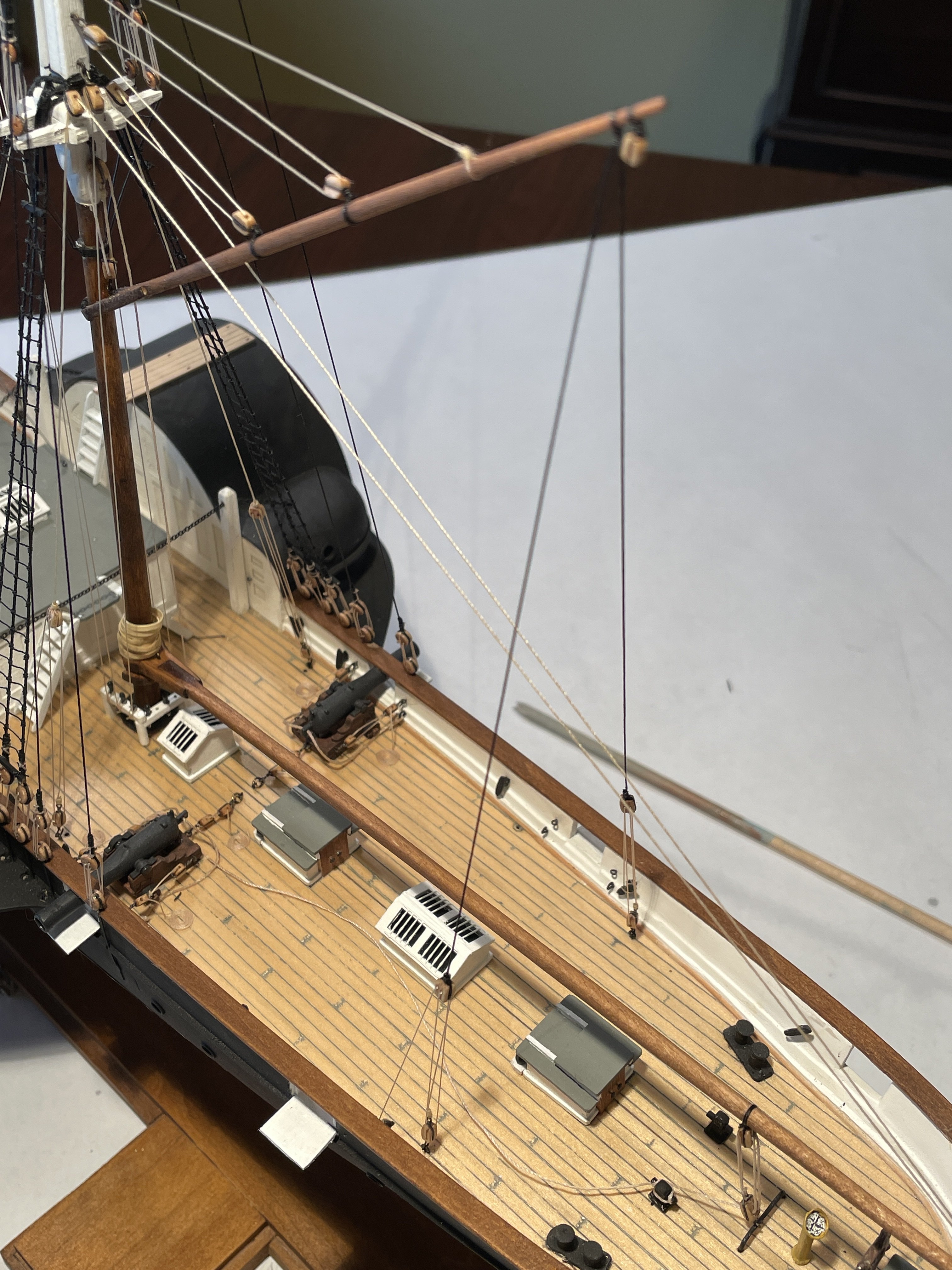
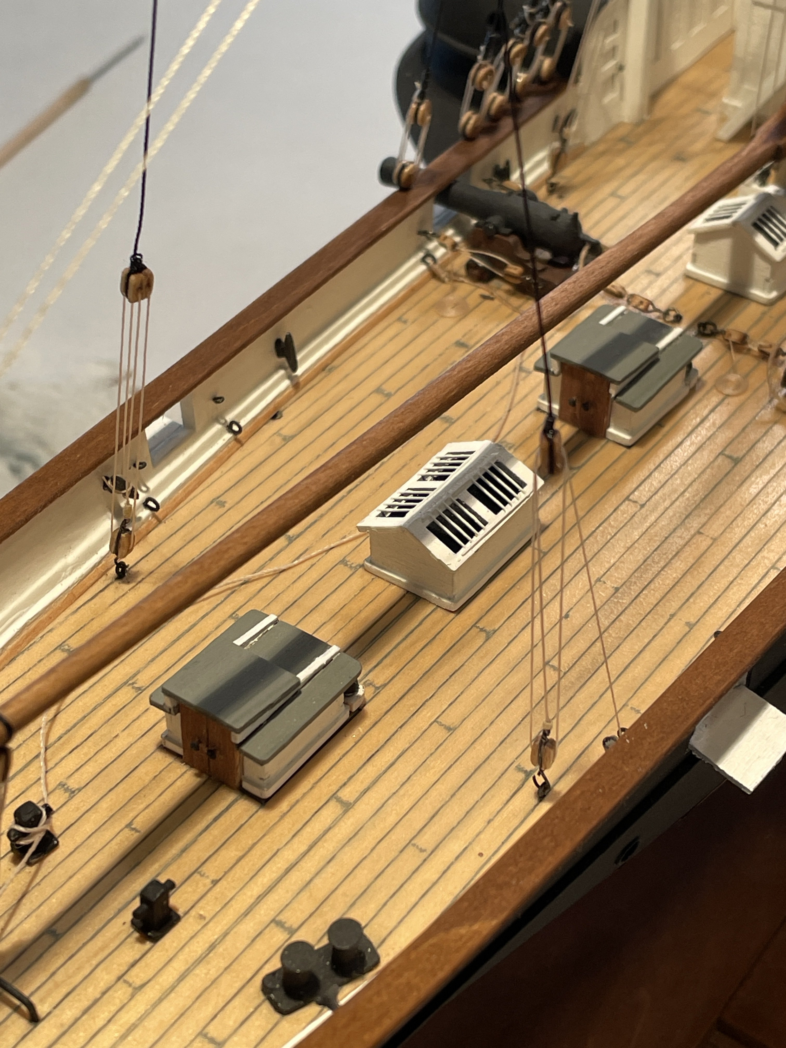
I wanted to use falls on the davits for the life boats and I also wanted to keep the boats above the rails. To do this however I noticed that the davits provided would not be high enough. In order to raise the davits I made up some extensions out of 1/8” diameter dowel.
The davits were installed a little farther back than what was called for in the instructions to keep the boats clear of the aft cannons.
The falls were added to the davits and rigged to the boats.
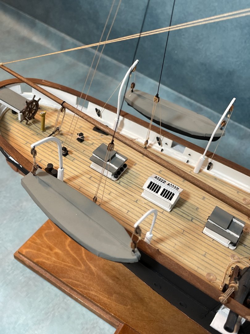


Looking back I'm glad I changed the configuration of the lower yard brace because it would have been a real bear working around it trying to install these boats and the boom and gaff.
-
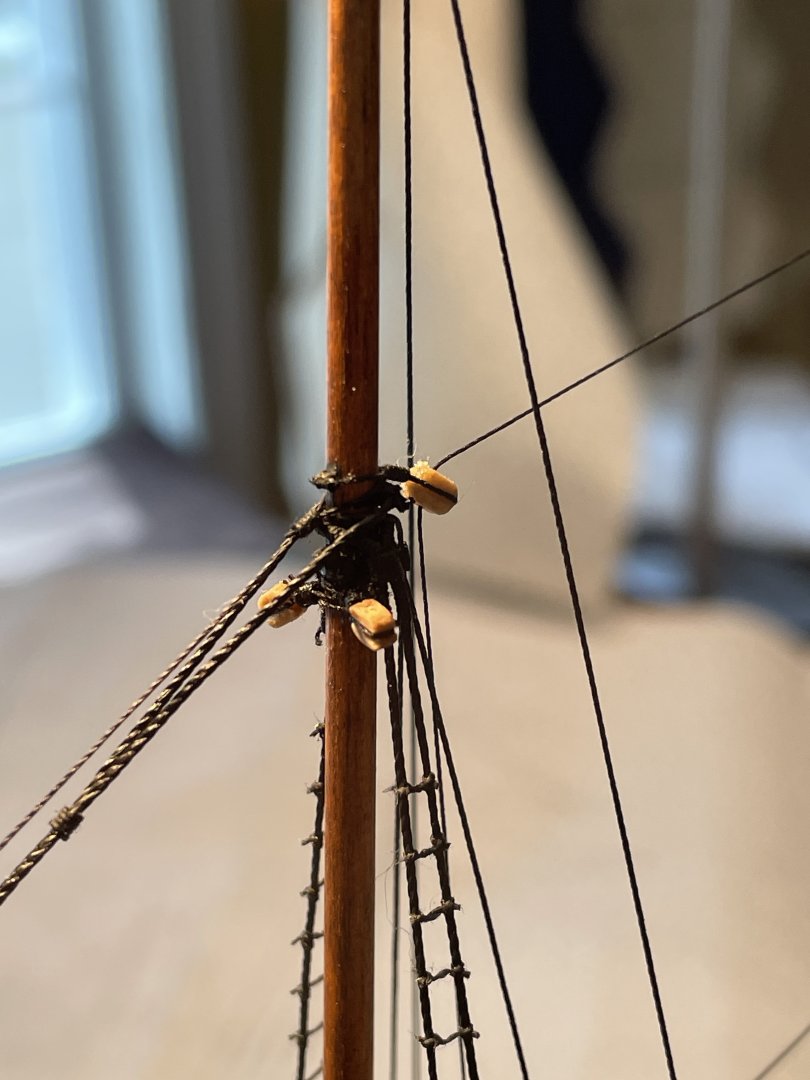
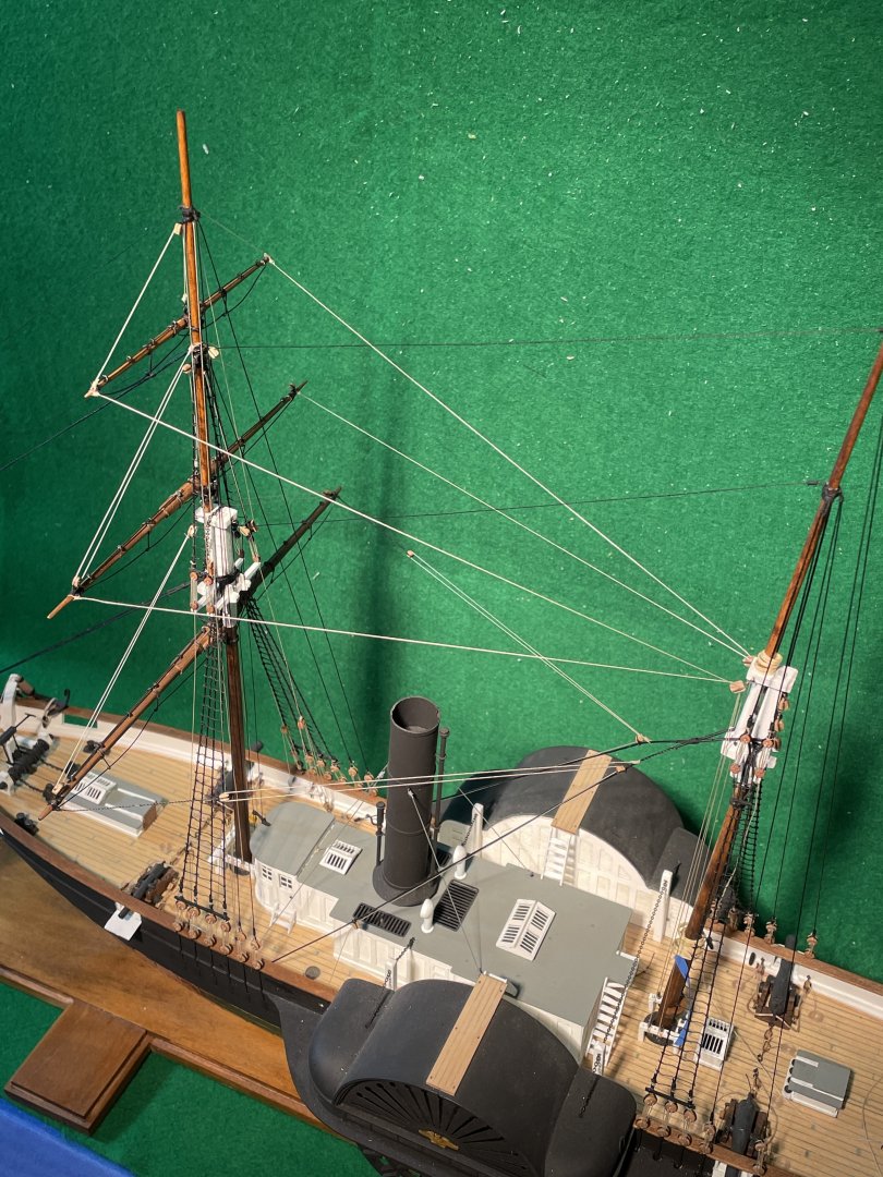
Moving right along now!
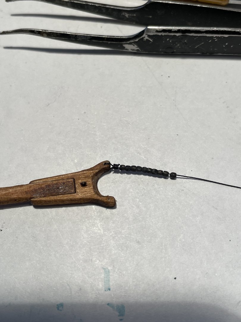
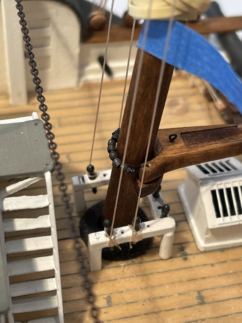
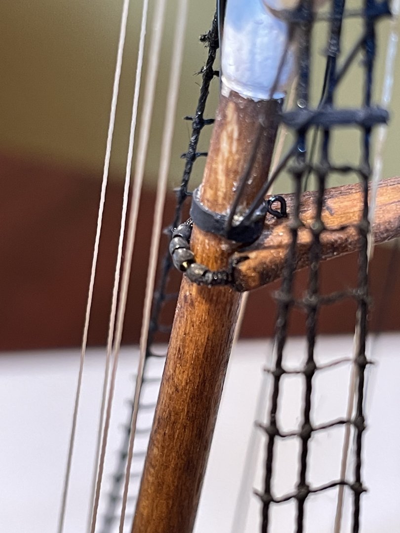
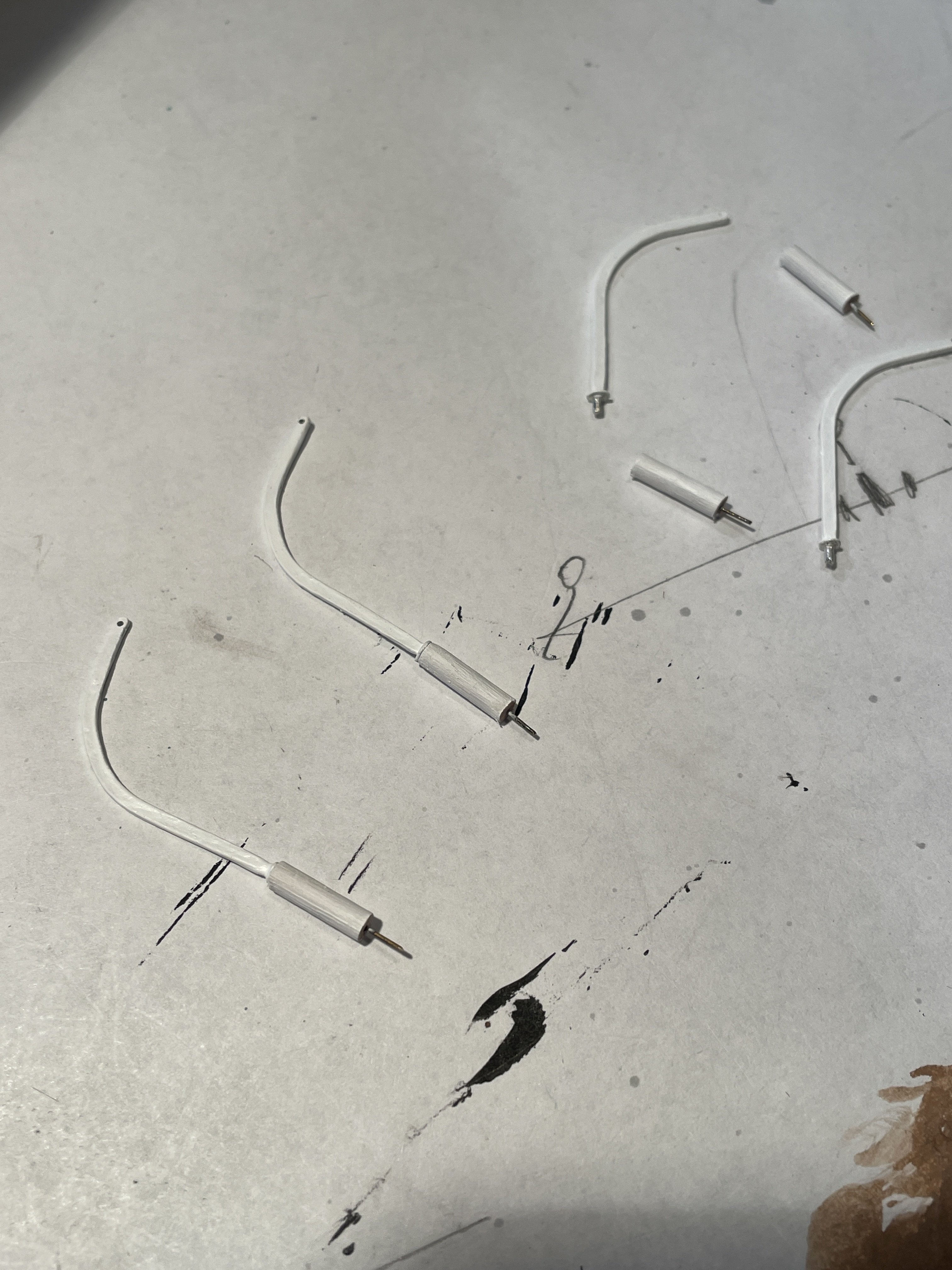
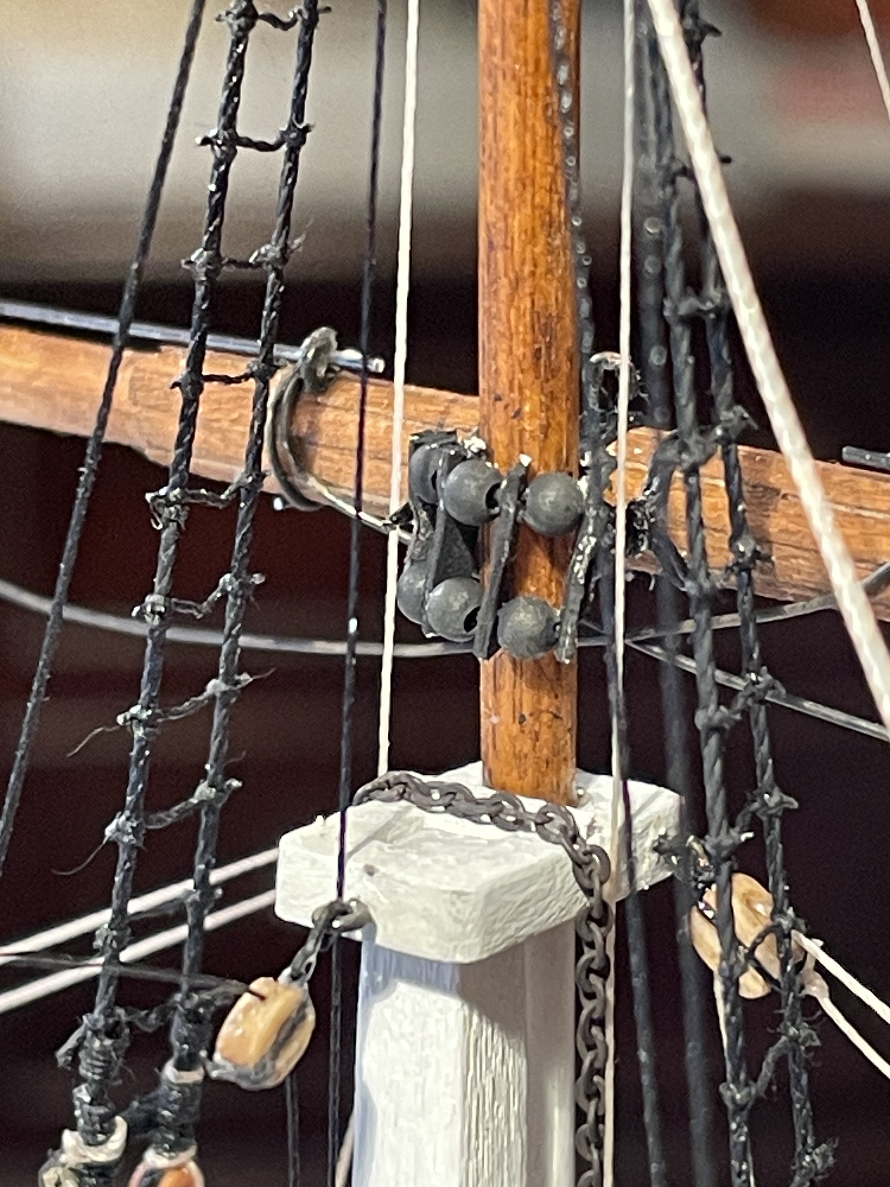
Boom parral
For the boom parral I used a different size jewelry bead that I blackened. Beads were threaded and tied around the main mast.

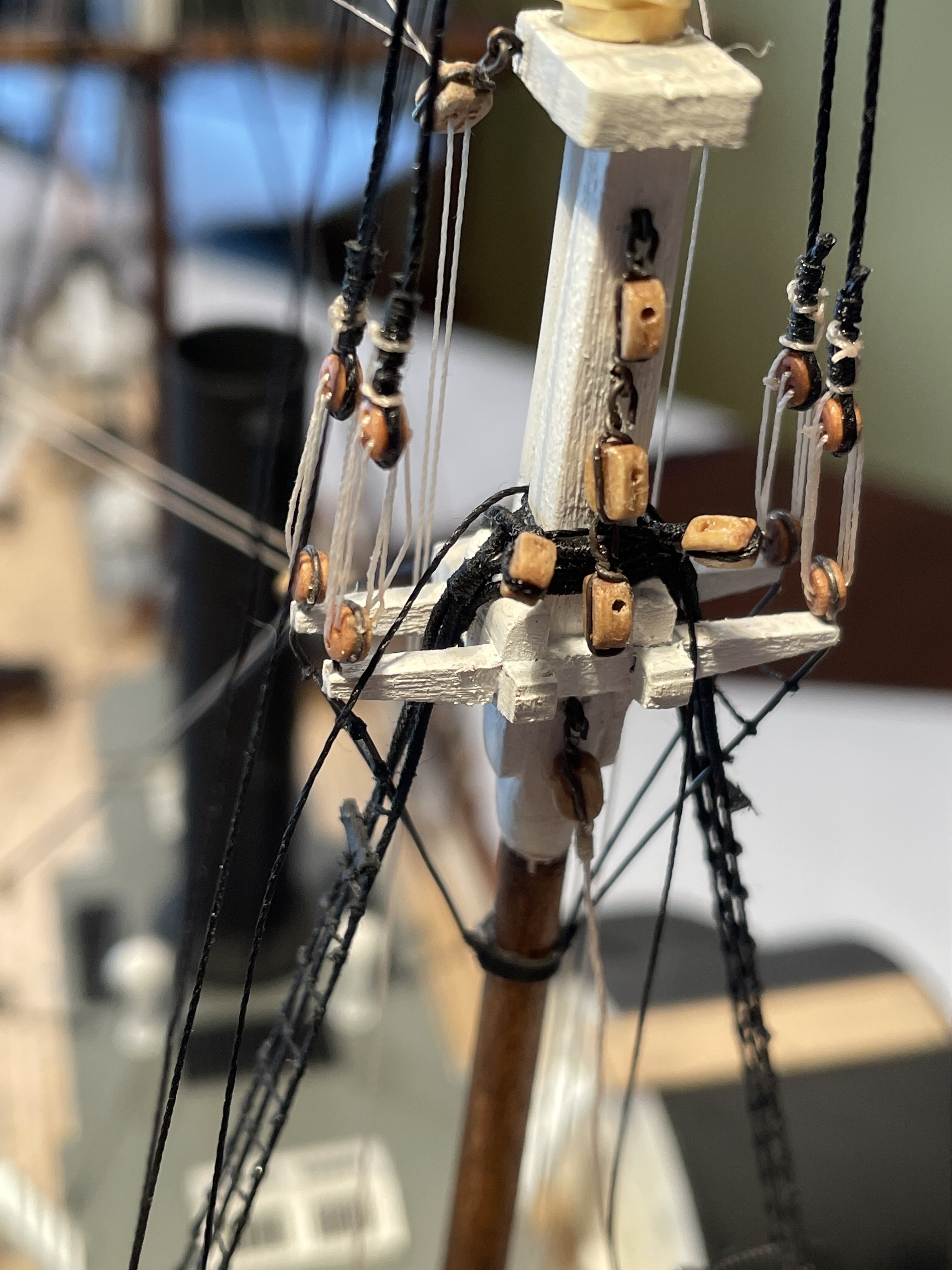
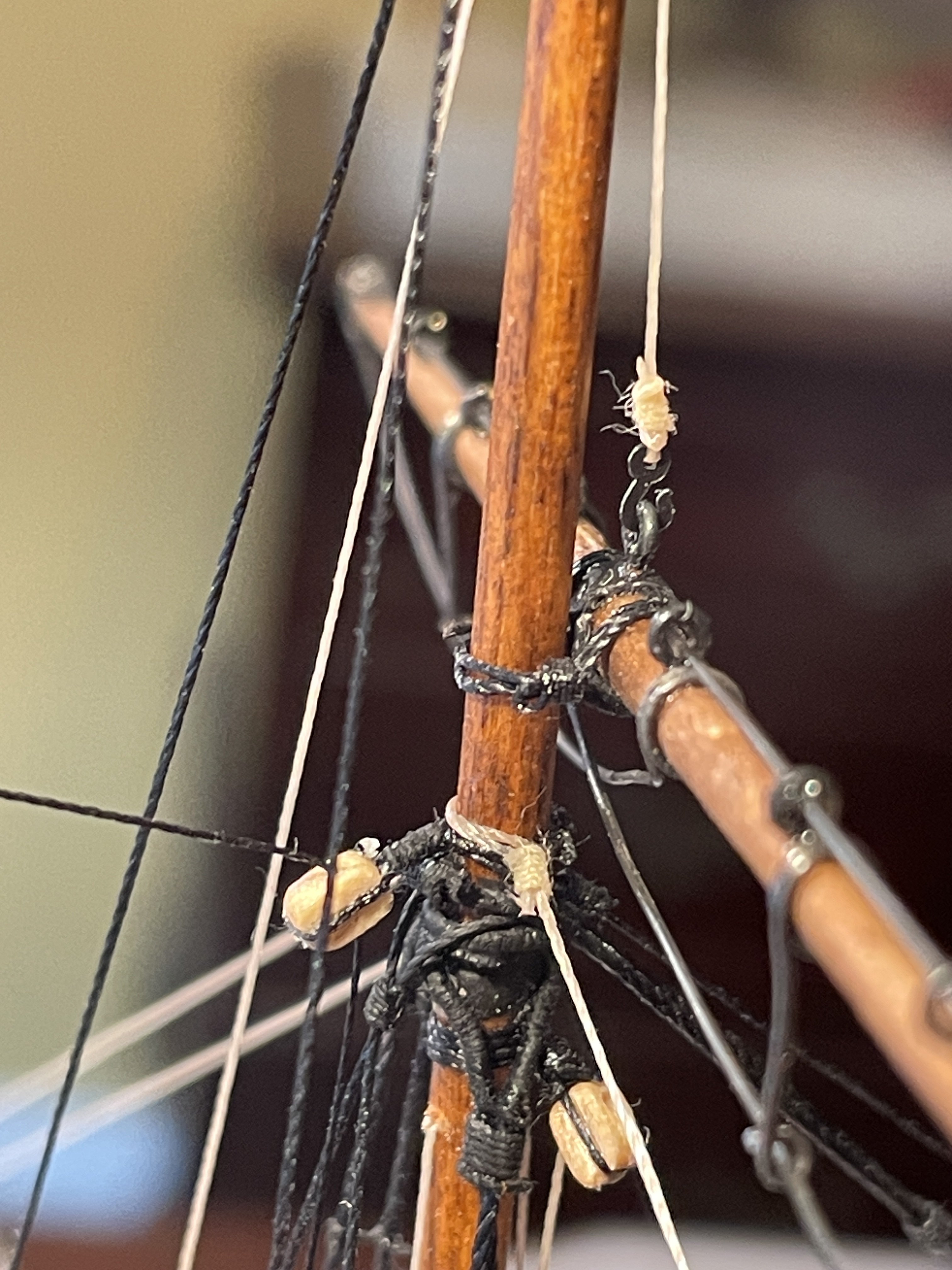
Topping lifts
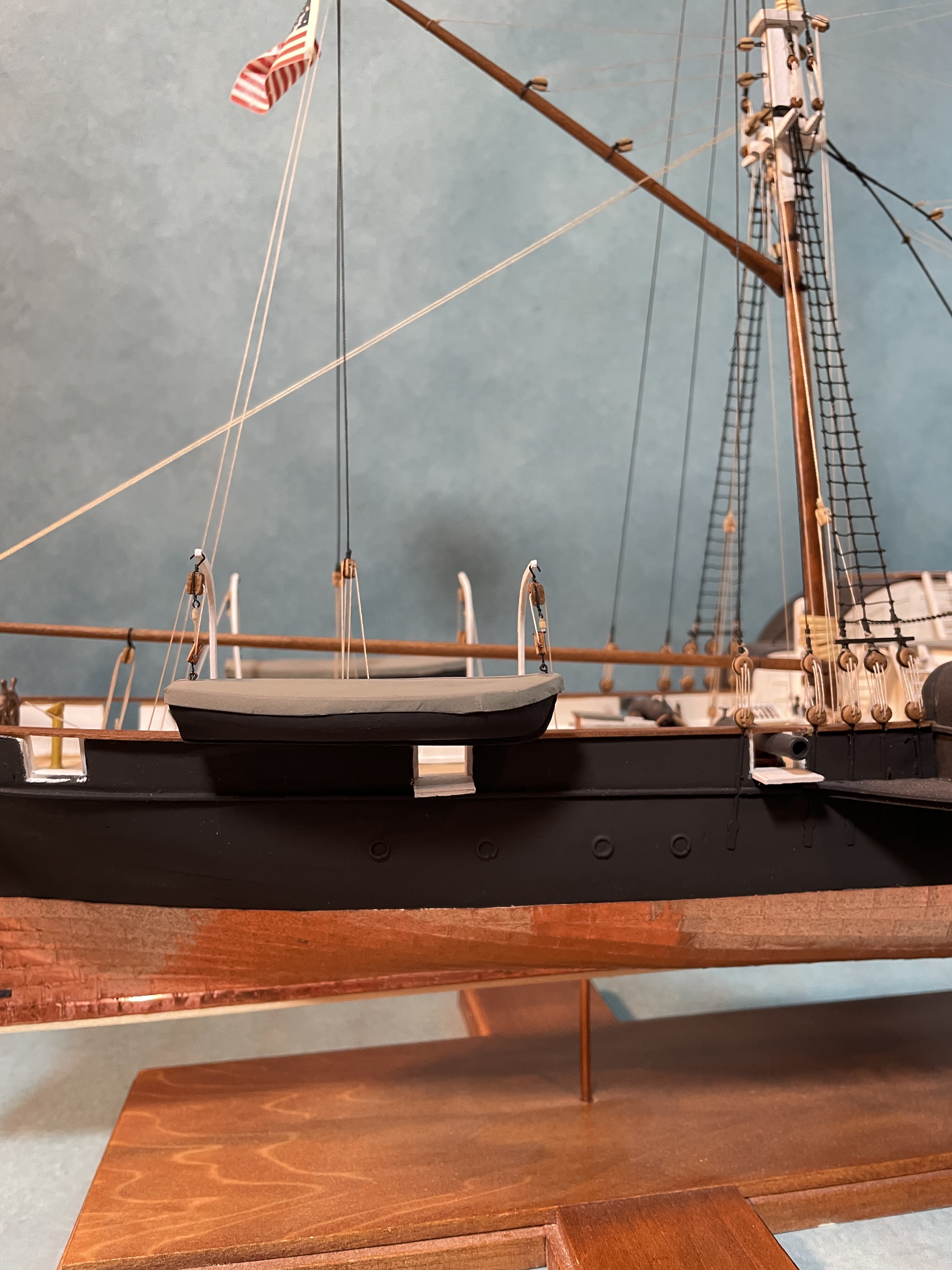
The topping lifts were installed per the instruction by first attaching two blocks above the main masthead.

The lift lines were run from the end of the boom through the blocks installed above the masthead then down to the deck. I did follow the superdetail described in the instructions by providing a block and tackle at the end of the lift lines. I used the cleat nearest the water closet to tie off the halliard.
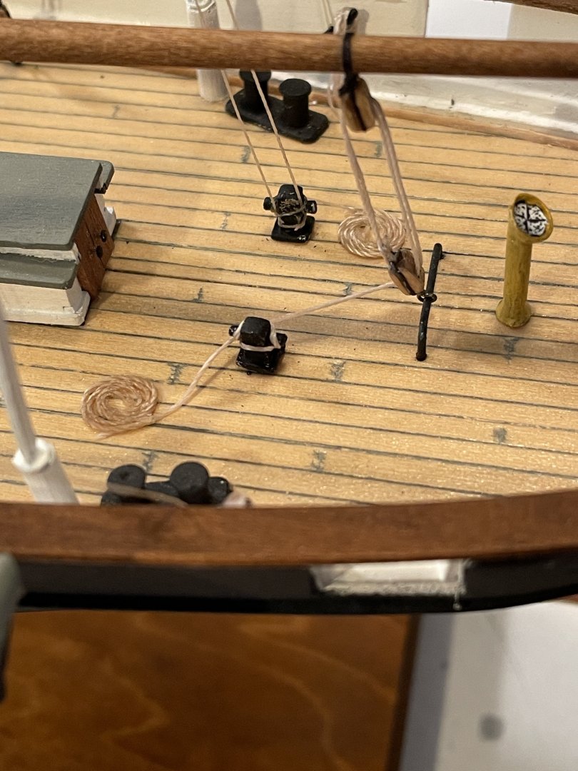
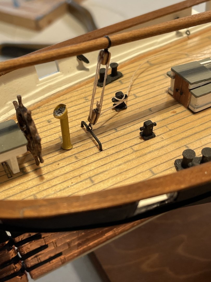
Main sheet
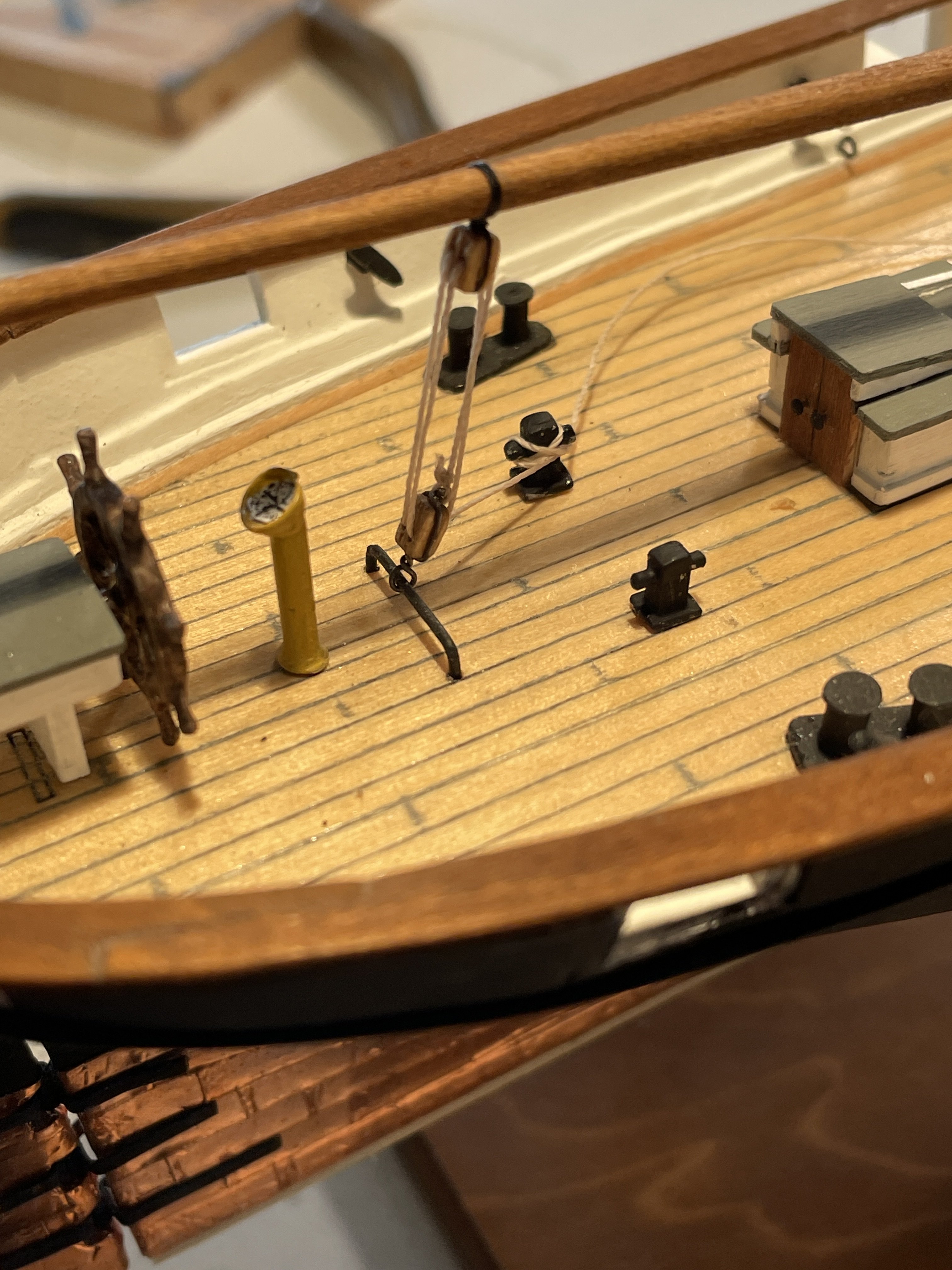
The main sheet was rigged from the block attached to the traveler to the block on the lower side of the boom. To tie this line off I used some small bollards I had left over from another build that I secured to the deck.
Gaff parral
The gaff parral was made similar to the boom parral.
Gaff throat halliard
The gaff throat halliard was installed per the instruction and belayed to the bitts at the deck. Sorry no picture.
Gaff peak halliard
The gaff peak halliard was also installed per the instructions and belayed to the bitts at the deck.

Vangs
The vangs were installed per the instructions and the halliards were tied off to existing cleats on the bulwarks.

-
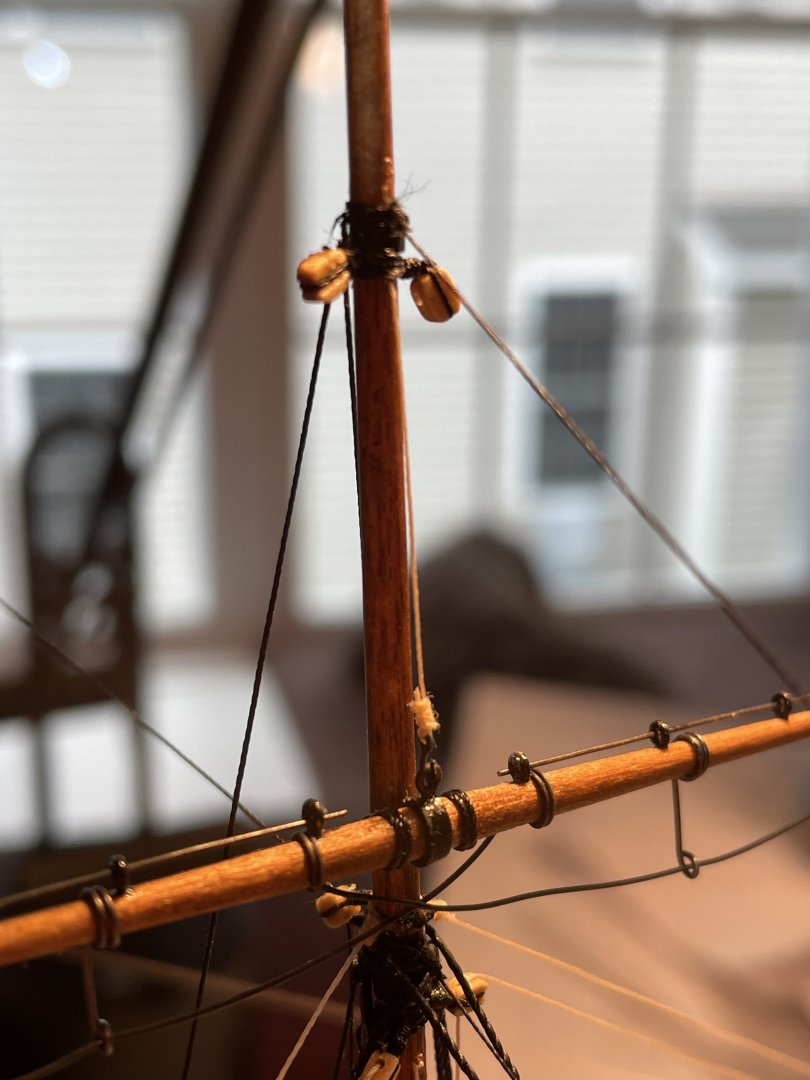
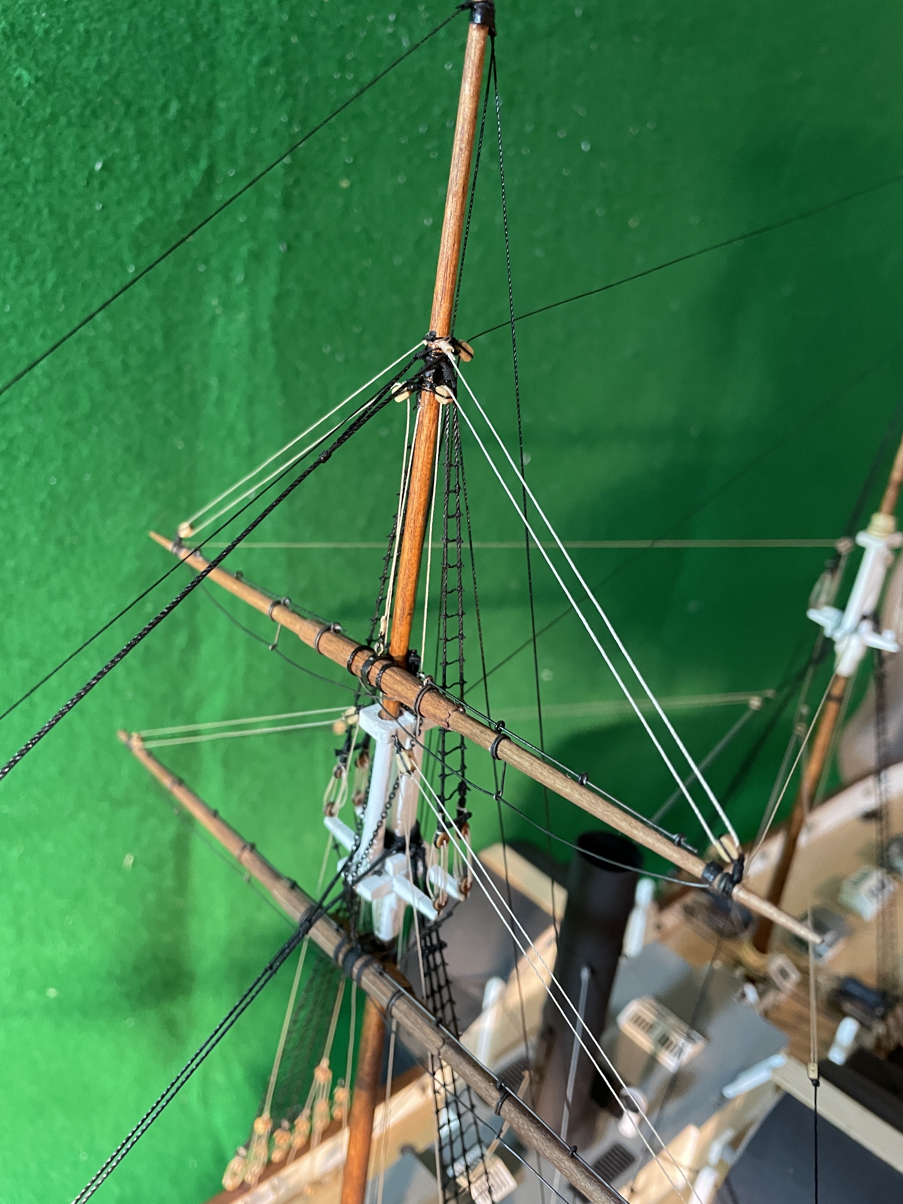
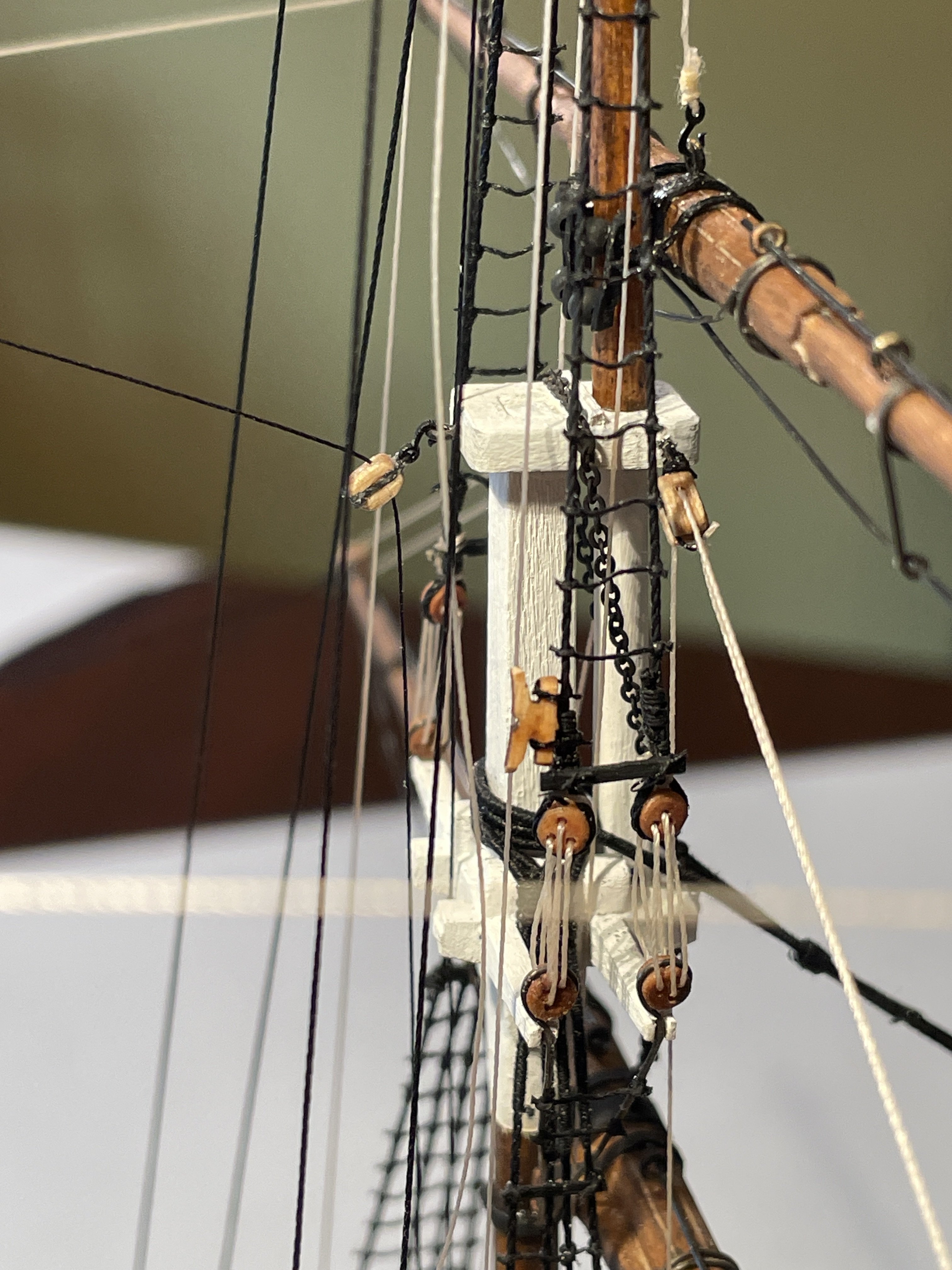
Topsail yard lift blocks
I decided to install the lift blocks on the mast for the topsail yard as shown in the instruction booklet.
Topsail yard lifts
The topsail yard lifts were installed similarly to the lower yard lifts by running the lines through the pulleys on the yard and mast and then brought down to a halliard near the bulwarks.


Topsail yard parral
For the topsail yard parral I used some small jewelry beads for the parral beads and pieces of cardstock for the trucks.

Topsail yard tye
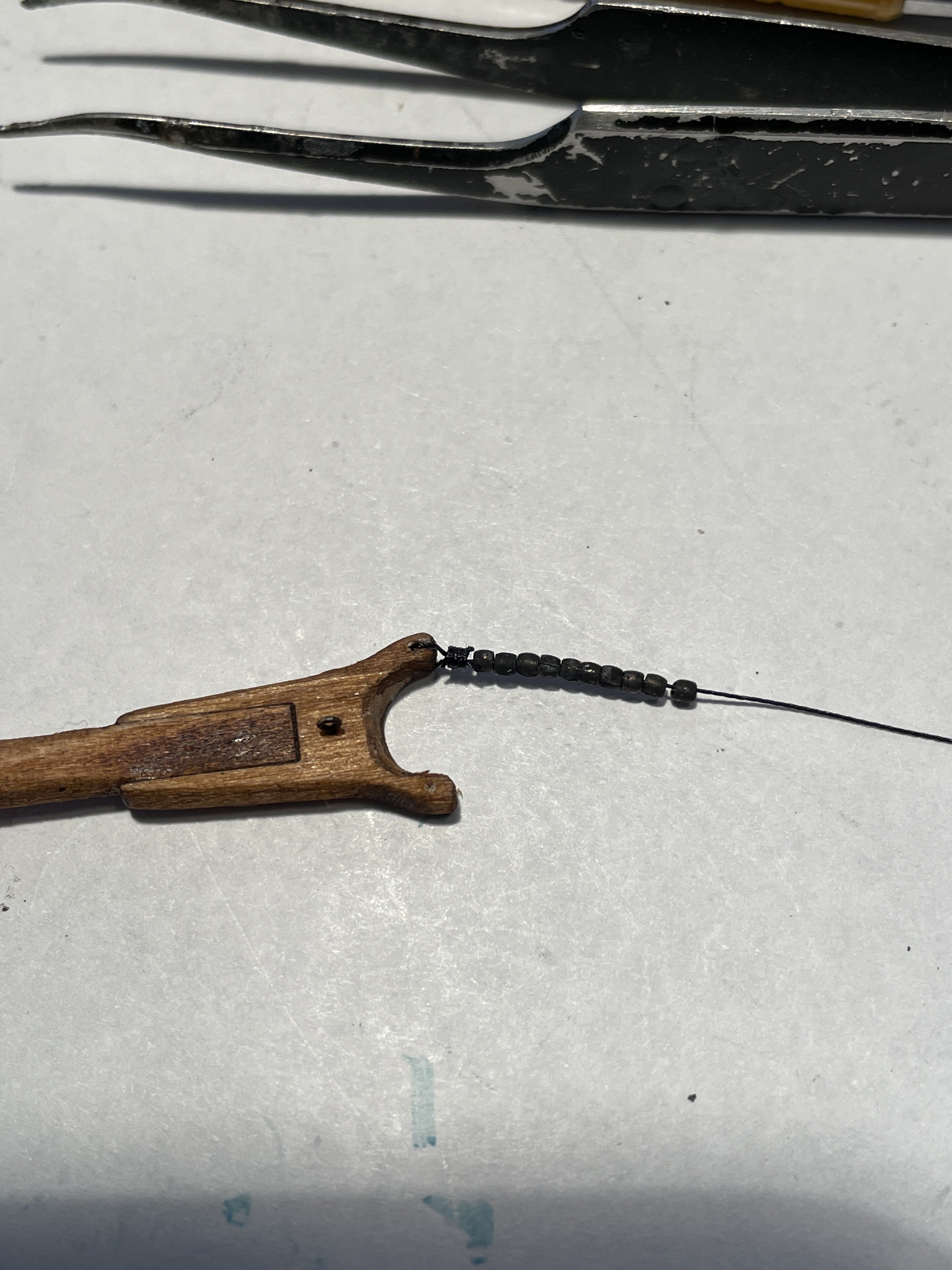
For the topsail yard tye I seized a hook to one end to attach to the eyebolt glued to the top of the topsail yard. The line was threaded through a hole I drilled (very carefully) through the mast just below the lower stop. The line was then brought down and belayed to the bitts at the deck.
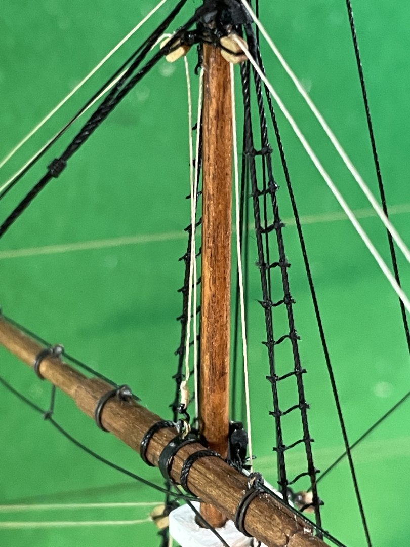
Topmast yard braces
The topmast yard braces were installed per the instructions taking the line aft, through the inner sheave of the double block on the main mast cap and down to belay at the bitts below.
Topgallant yard parral
For the topgallant yard parral I used some thinner back line.

Topgallant yard tye
The topgallant yard tye was done similar to the topsail yard tye. A hole was drilled again very carefully through the mast just below the upper stop. The line was belayed to the bitts on the deck.
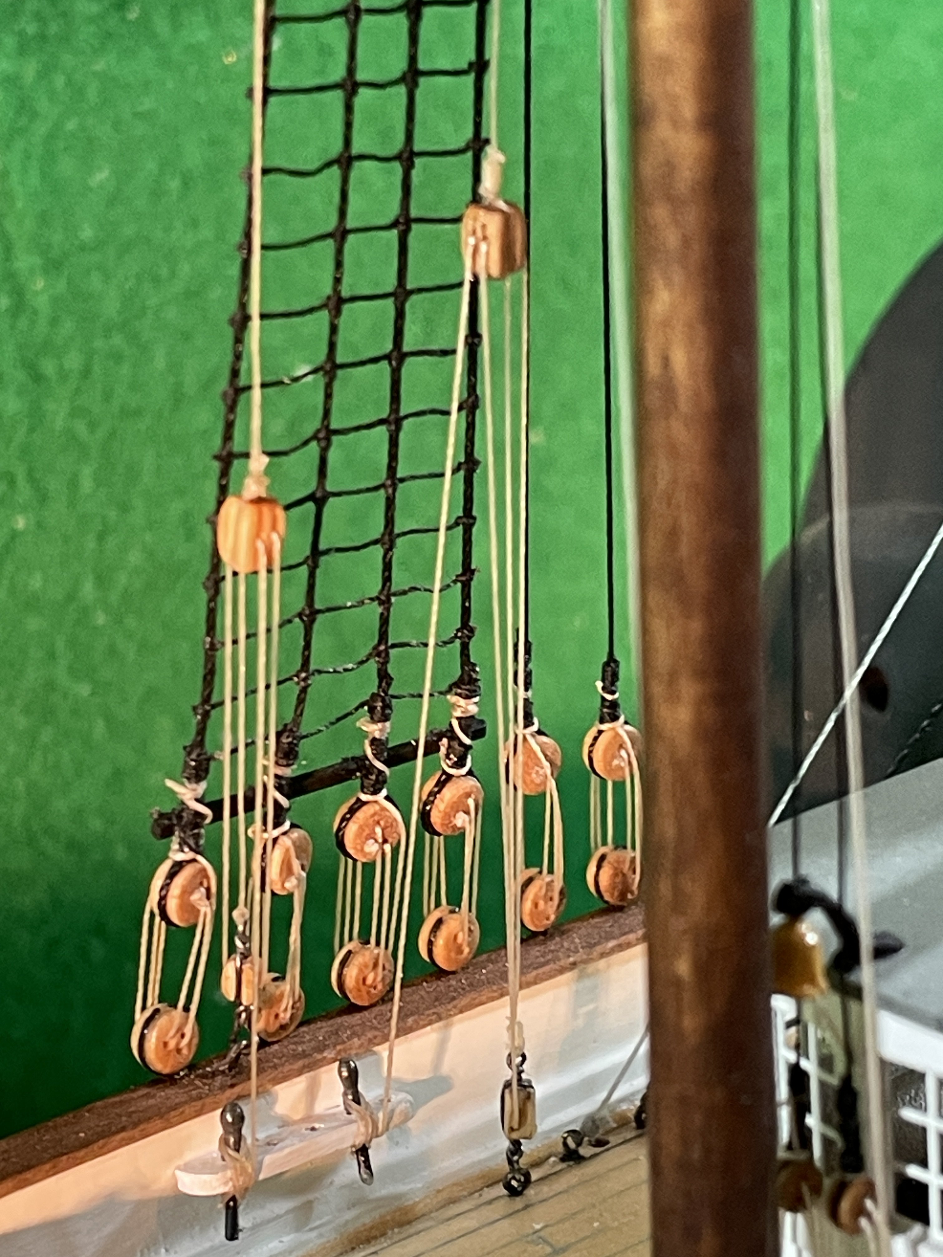
Topgallant yard lift blocks and lifts
The topgallant yard lift blocks were installed per the instructions. The lifts were run from the yard through the blocks on the mast and tied off to cleats installed on the shroud.

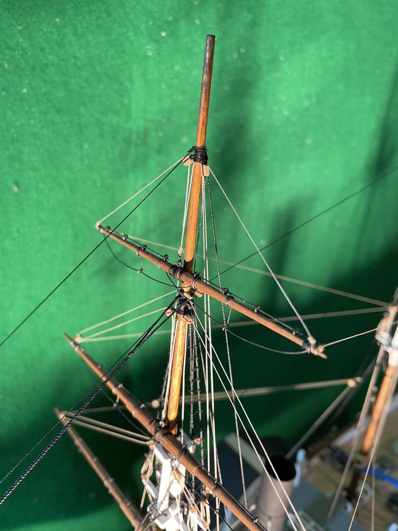
Topgallant yard braces
The braces were installed as per the instruction the line running aft to the outer sheaves in the double block at the main mast cap then down to belay at the bitts.
-
-
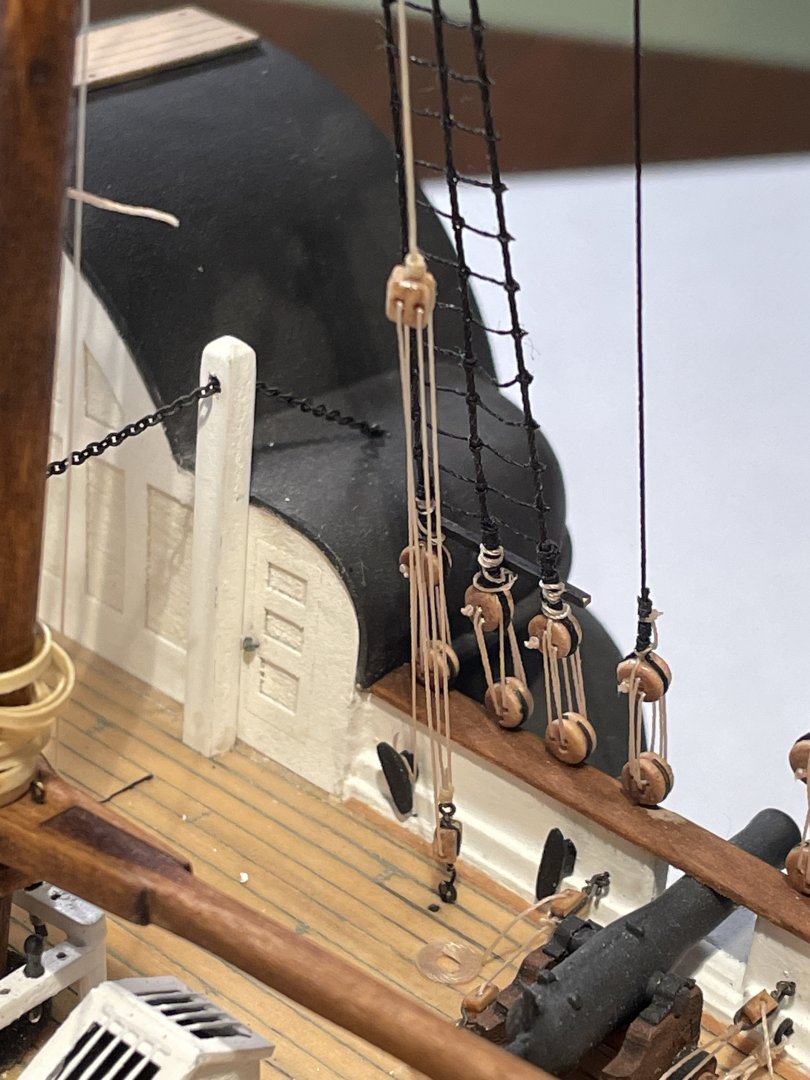
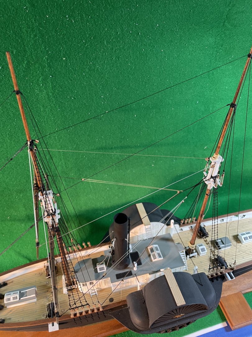
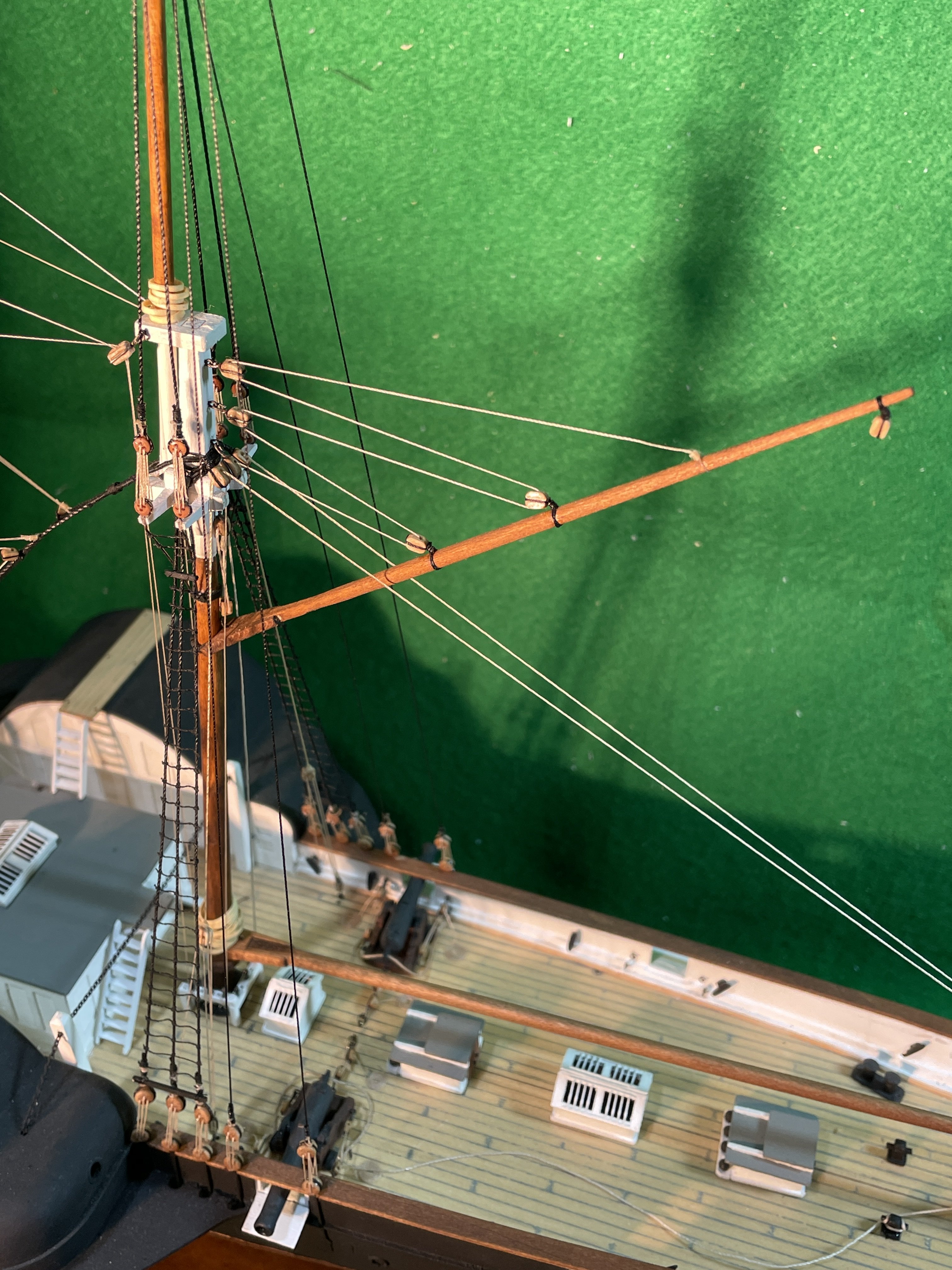
Fore lower yard braces
As per the instructions the rigging for these braces is to run from the pendants back to cleats located at the stern of the ship. However after studying bobandlucy’s Harriet Lane build I decided to change this rigging a bit. The reason for this change was that while studying bob’s build I noticed that his lifeboat placement interfered with the midship gun ports. To avoid this I thought I would move the lifeboats farther astern. If I did this though, then the lifeboat stanchions would interfere with the lower yard brace rigging. My solution was to start the rigging tied to the main stay then through the block on the end of the pendant then back to a block fastened lower down on the main stay to another block fastened farther down on the main stay and then tied off to a cleat on the bulwarks.


The hardest part of doing this was attaching the cleat to the inside of the bulwark. If you look at the picture above you’ll notice a little hole in the side of the hull that goes all the way through. That’s the only way I could drill the hole to attach the cleat on the inside of the bulwark. Now I need to fill the hole and paint.


NORDKAP 476 by _SalD_ - Billing Boats - 1:50 - RADIO
in - Kit build logs for subjects built from 1901 - Present Day
Posted
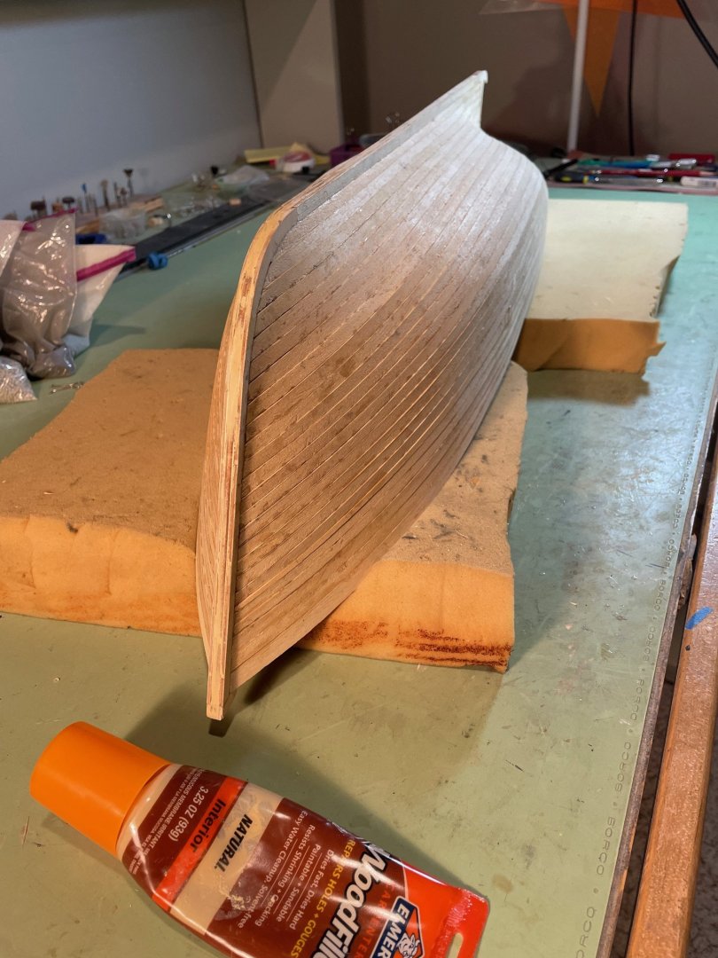
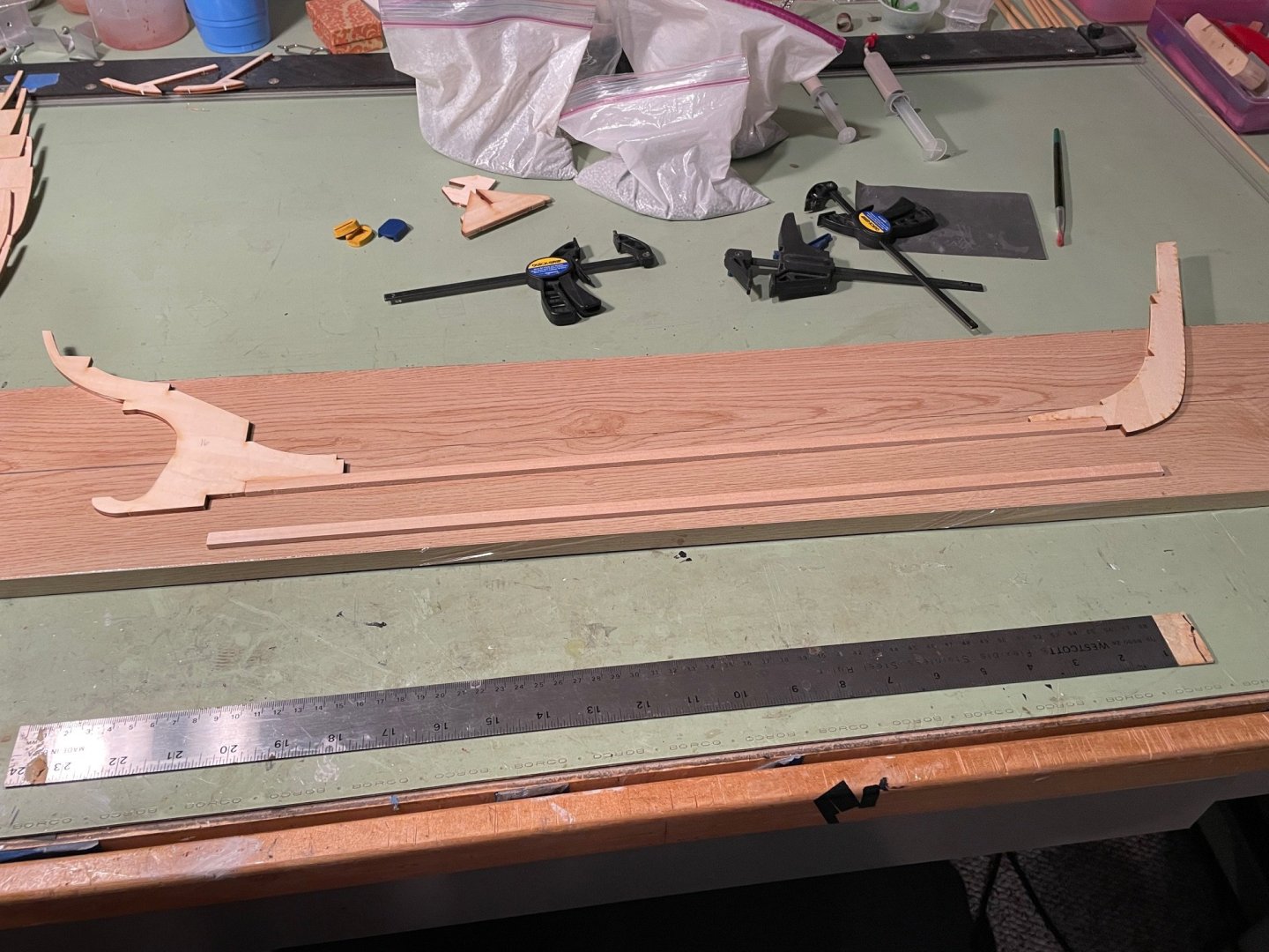
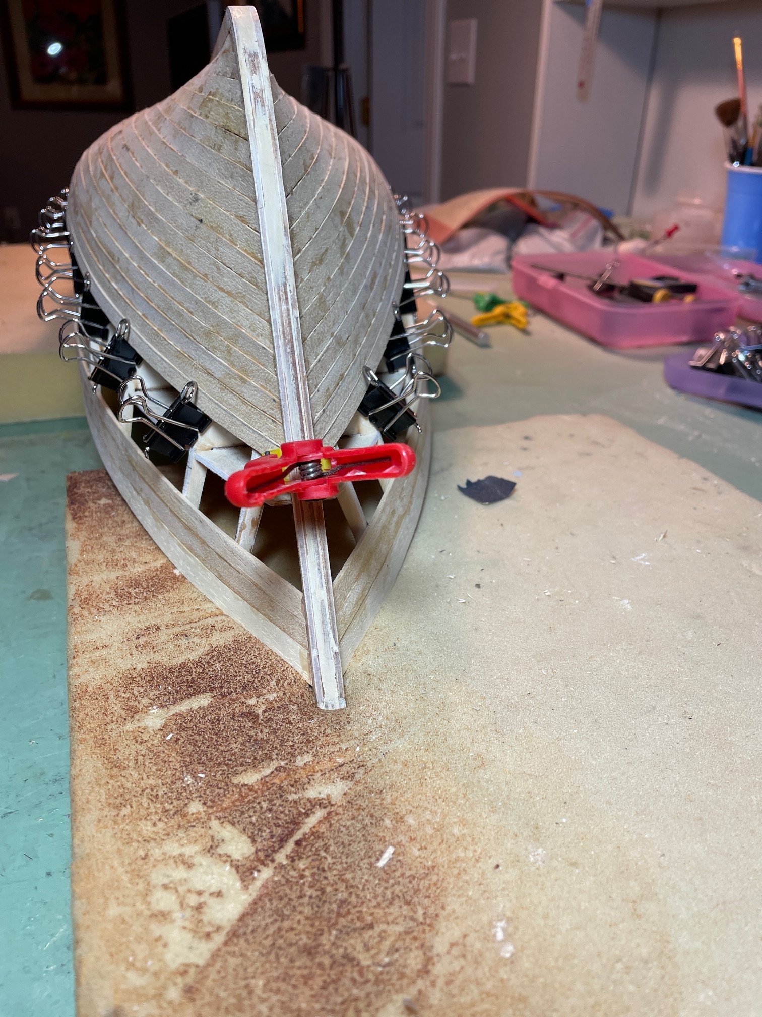
Waterproofing the Hull
After completing the sanding of the hull, I was ready to try something I had never done before on one of my ships—waterproofing the hull. After studying roddurant’s build log, I decided to use Eze-Kote Finishing Resin by Deluxe, along with Deluxe Materials Super Lightweight Fiberglass Cloth (1.0 oz).
My first step was to apply two coats of Eze-Kote to the hull, sanding between coats with 300-grit sandpaper. The resin is pleasant to work with—no odor, it goes on easily and cleans up quickly with water.
Next, I positioned the fiberglass cloth on the hull, working on one side at a time. I applied the Eze-Kote using a one-inch-wide paintbrush, working the resin into the cloth starting at the keel center and moving outward toward the stem and stern. After allowing the resin to dry overnight, I trimmed the excess cloth and repeated the process on the other side. Cleaning my basement hence all the 'priceless' junk on my work table.
Once both sides were glassed and trimmed, I applied two additional coats of Eze-Kote over the fiberglass, again sanding between coats with 300-grit paper. I also applied a single coat of resin to the interior of the hull—at least in the areas I could reach. Then came the big test! I inserted the prop and rudder post and...
IT FLOATS. No runs, no drips no errors, as they say.