


_SalD_
-
Posts
757 -
Joined
-
Last visited
Content Type
Profiles
Forums
Gallery
Events
Posts posted by _SalD_
-
-
-
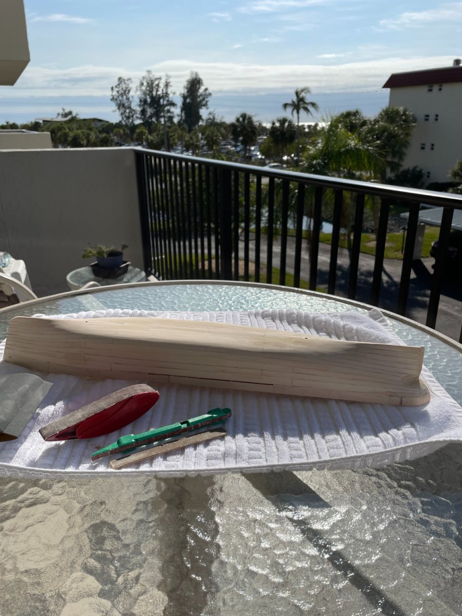
Thanks druxey and thanks for all the likes.
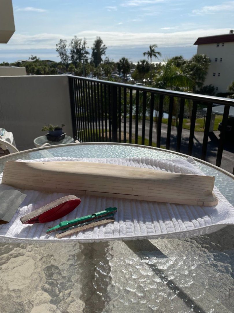
No workshop but at least I have a nice view while sanding.
- Canute, Rudolf, Prowler901 and 4 others
-
 7
7
-
-
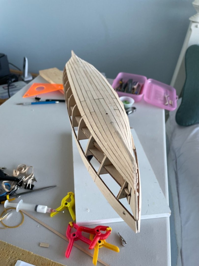
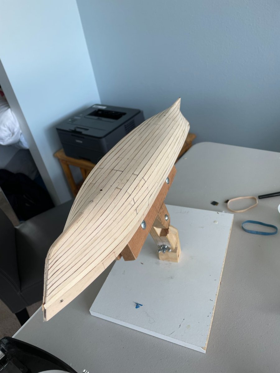
Used the first two sheets of planking which did approximately half the hull. All the port fore pieces had to be sanded down to match the width of the starboard side. All of the port and starboard center and aft pieces were the same size so no sanding was required for them.

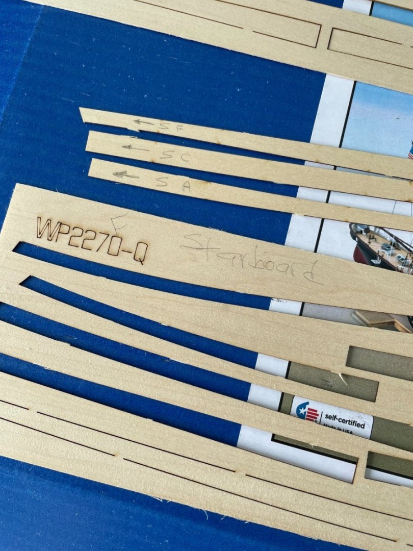
I also found it very helpful to label the back of each piece to avoid confusion as to what side and in what direction the planks go after they are removed from the sheet.
- Canute, Prowler901 and druxey
-
3
-
-
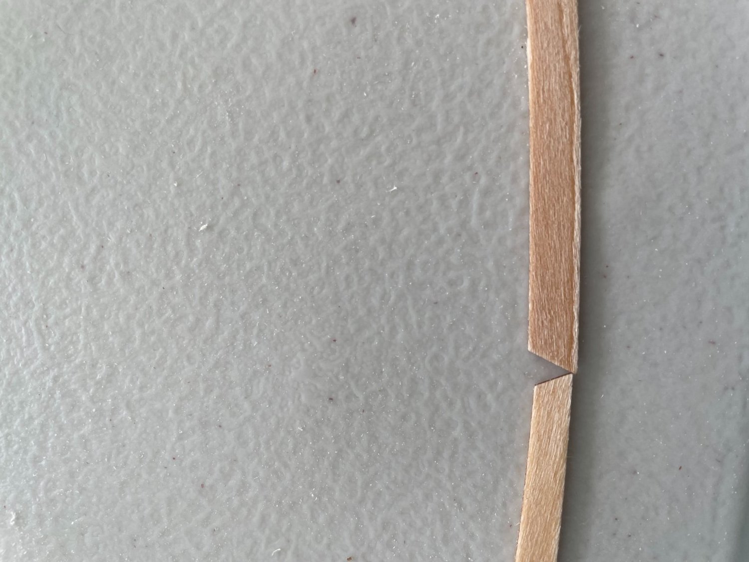
Planking the hull:
The kit comes with four sheets of pre-formed hull planking, two for the port side and two for the starboard side. The sheets are well labeled so you know where each piece belongs. Starting with the first two fore pieces, port and starboard, I noticed that they were not the same width. The port plank being quite a bit larger than the starboard one.
Going on the assumption that the planking should be symmetrical on each side of the hull, I choose to sand down the port plank making it the same width as the starboard side.
First set of fore and aft planking pieces in place.
Planking continues
Thank you for looking in and I appreciate the likes.
- Rudolf, Prowler901, Jack12477 and 2 others
-
5
-
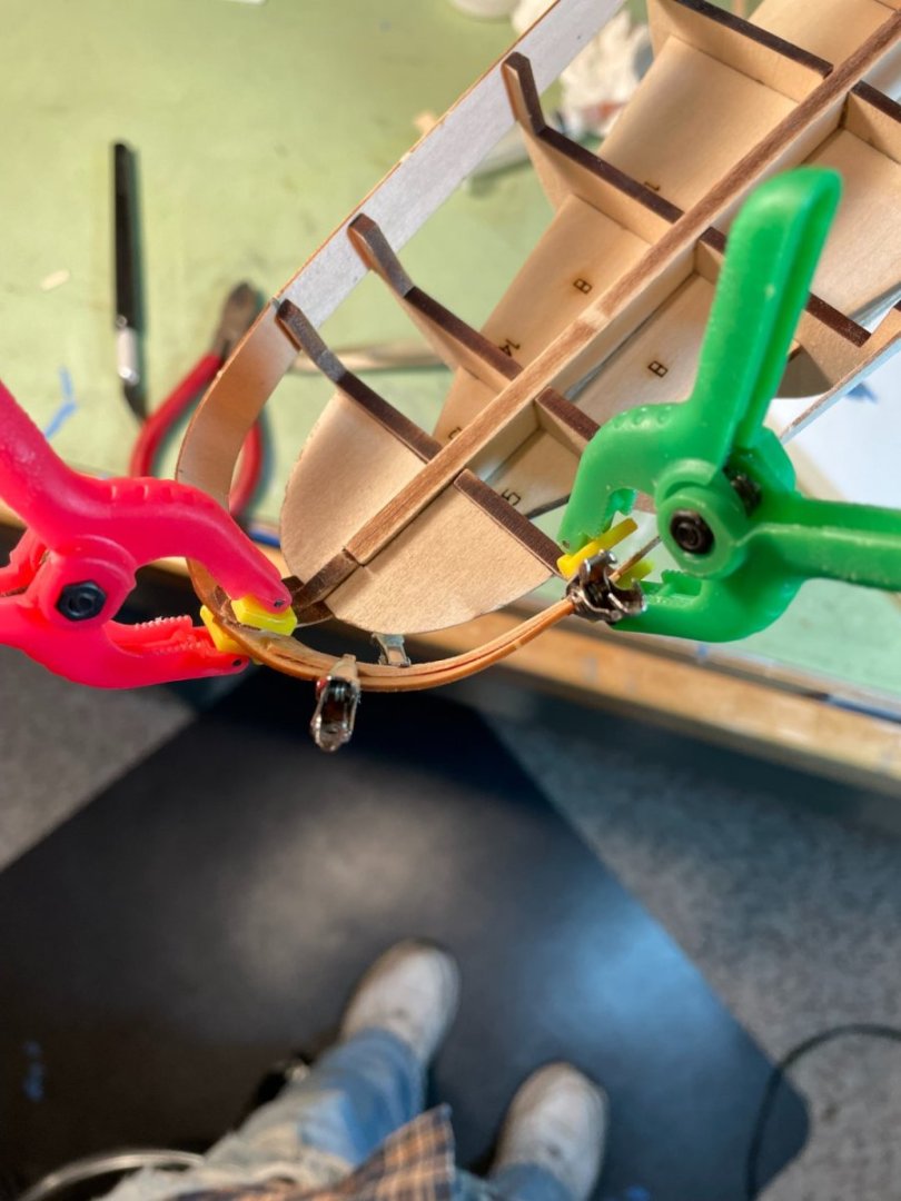
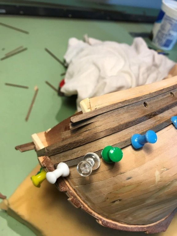
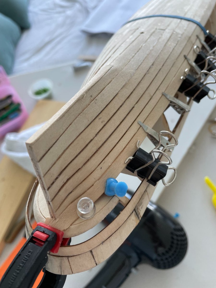
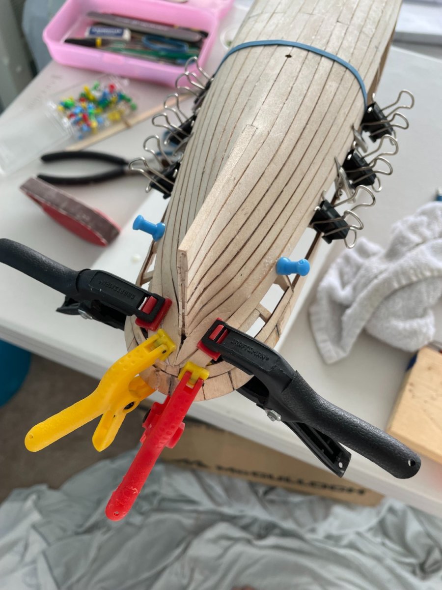
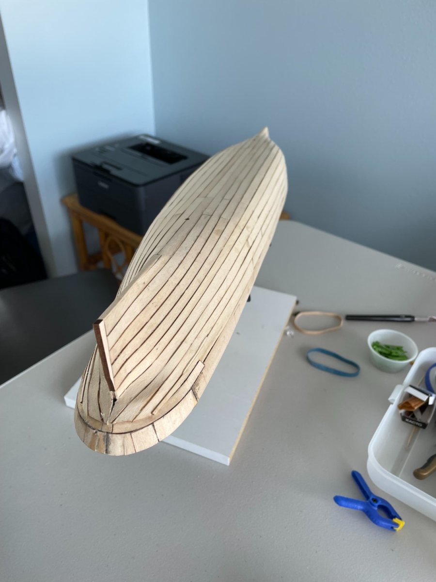
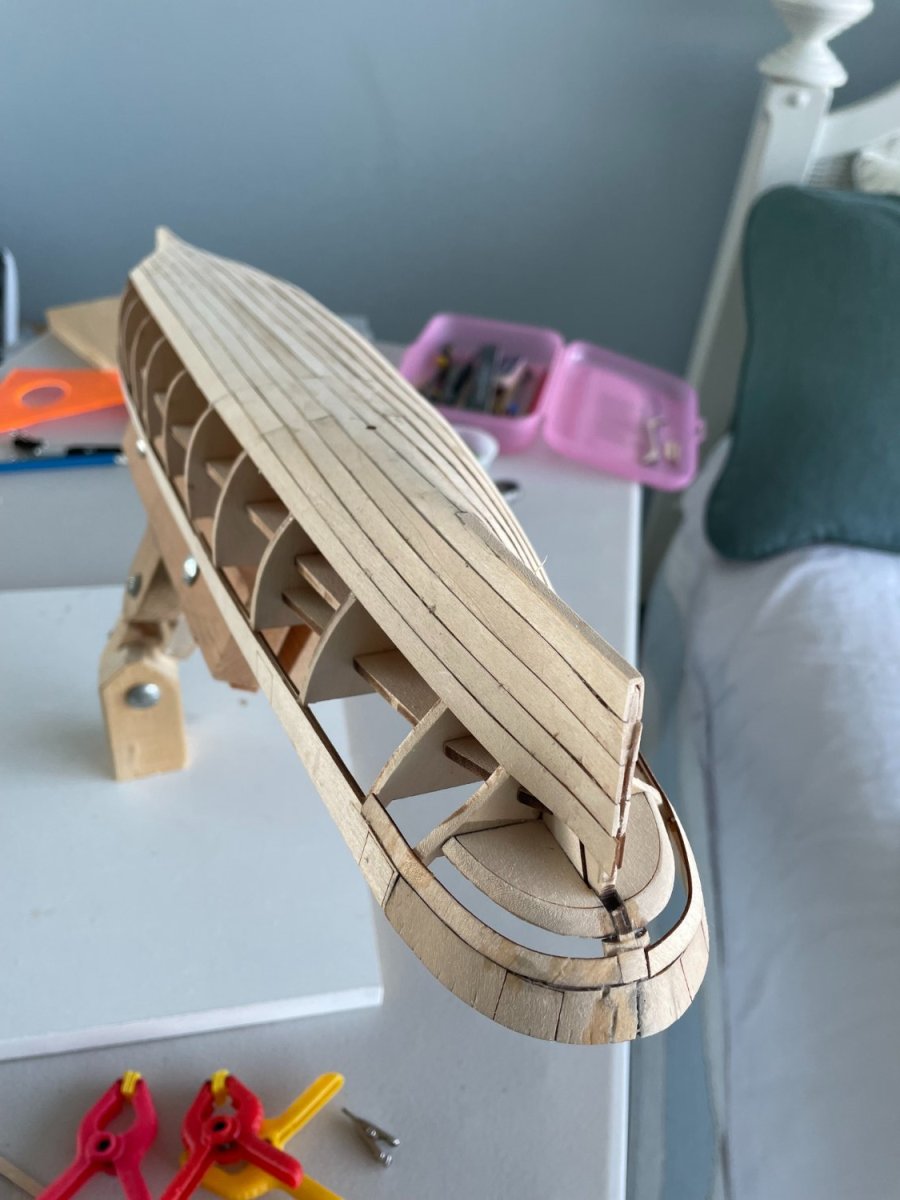
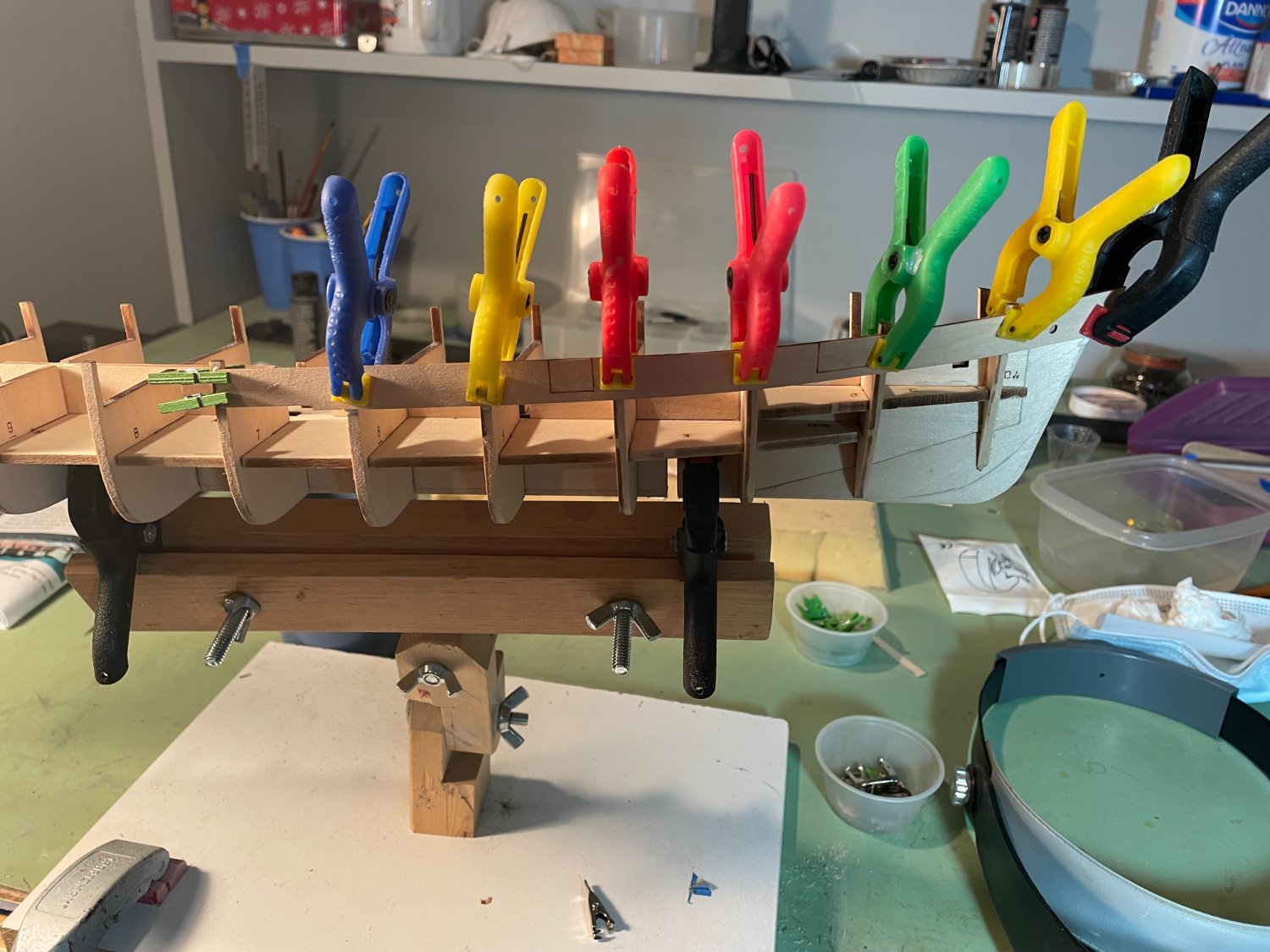
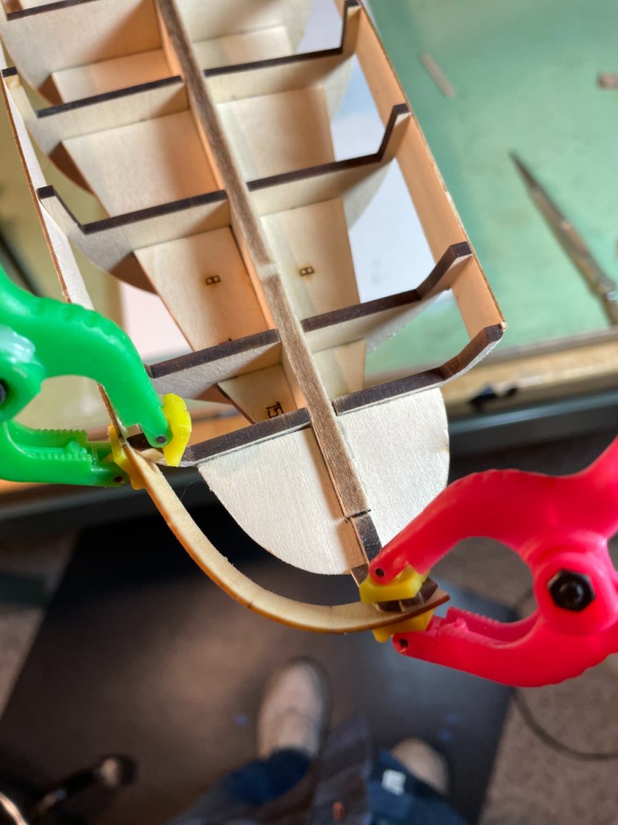
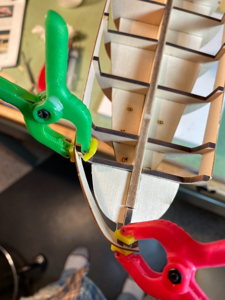
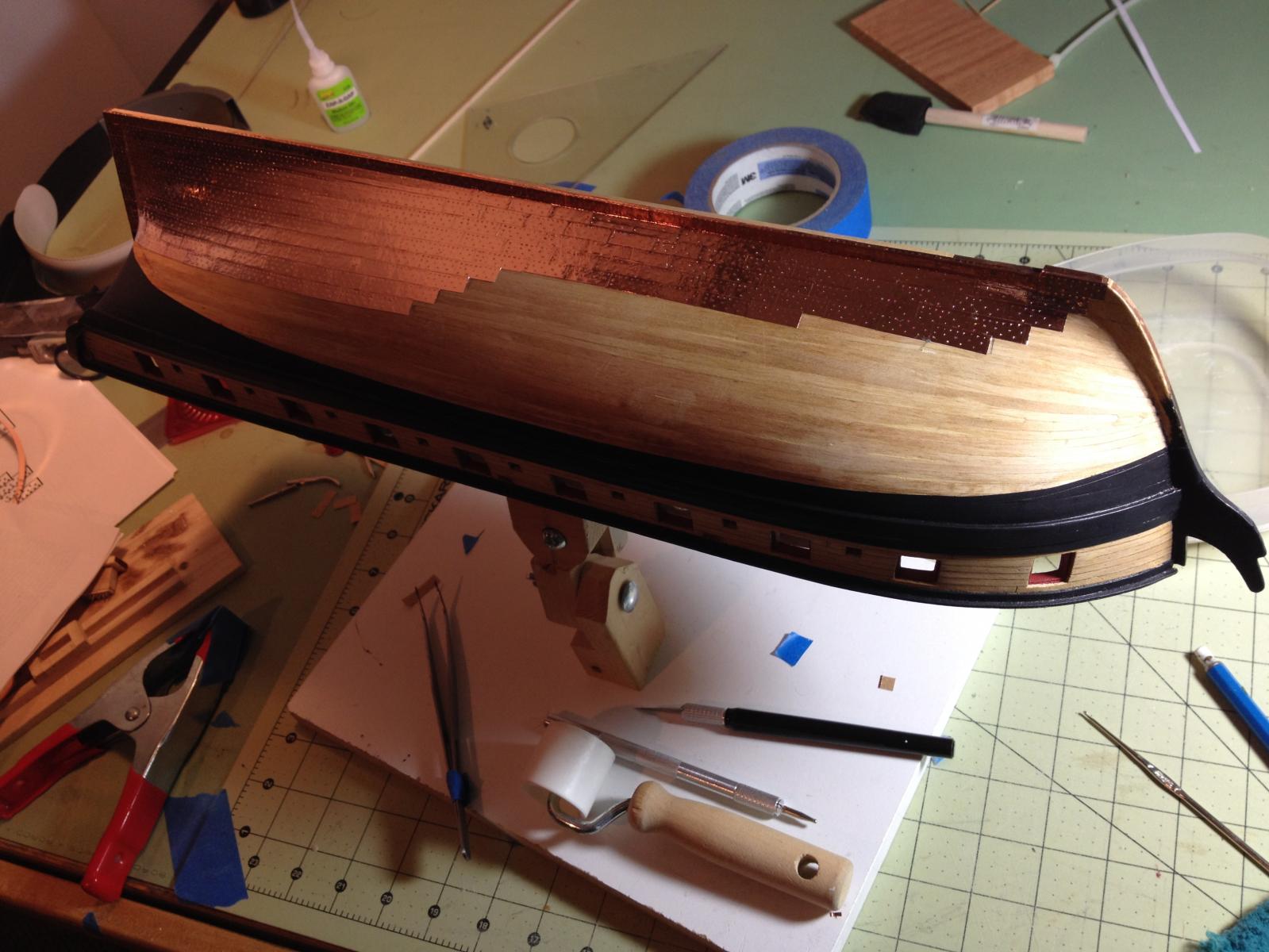
Garboard strake:
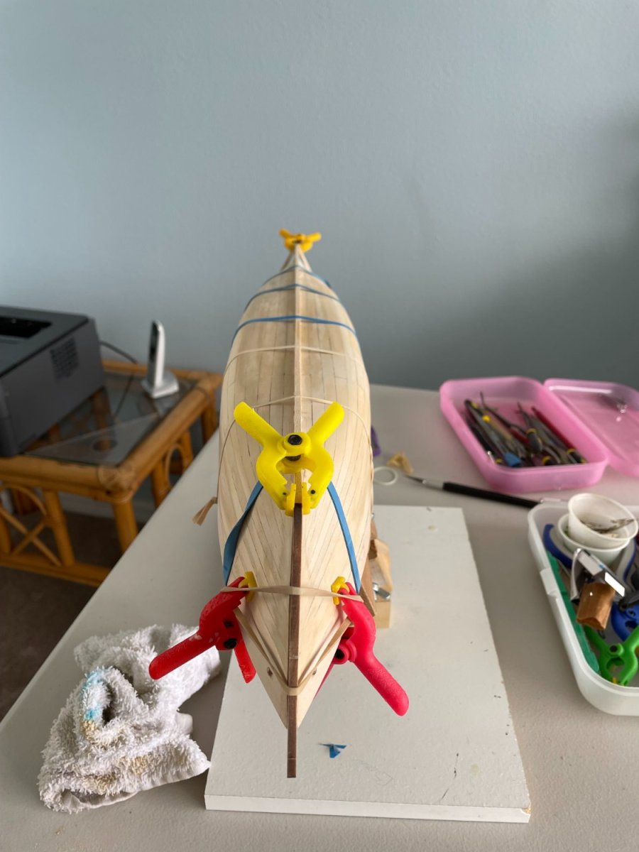
Before fitting the garboard strake to the bulkheads I penciled in a centerline on the inner keel pieces to help align the planks.
Beginning with the fore plank, it was soaked in hot water and then clamped in position on the hull. These pieces were allowed to dry and then glued in place. The same procedure was followed for the aft garboard strake. After the fore and aft pieces were set the center section was fitted in between them and glued in place.

You may have noticed, and maybe you haven’t, but the picture background has changed. This is because I am back at my residence in Florida. The previous photos were at my house in Connecticut where we spend the holidays with the family and a few of months in the summer. My main workshop is still in Connecticut so I am relegated to the spare bedroom down here. Most of my toys…I mean tools are still in Connecticut so I will try to make do with what I have.
Thank you for all the likes.
- Rudolf, Jack12477, Prowler901 and 2 others
-
5
-
-
Thanks druxey. The stern pieces are fragile and need to be handled gently. Like my uncle the plumber would say while bending copper tubing, 'you need soft hands'.
- bobandlucy, druxey and Canute
-
3
-
Thank you all for the likes
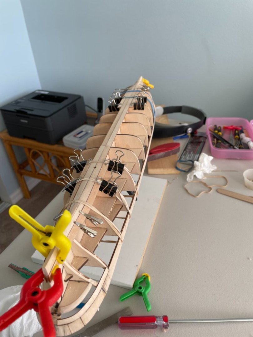
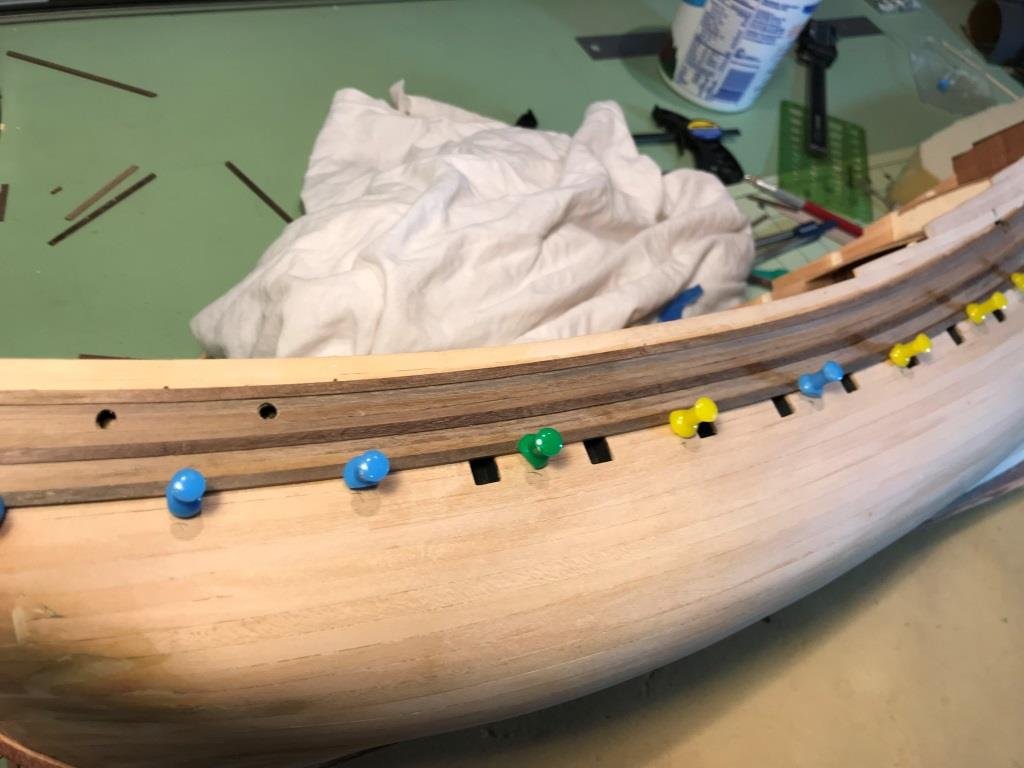
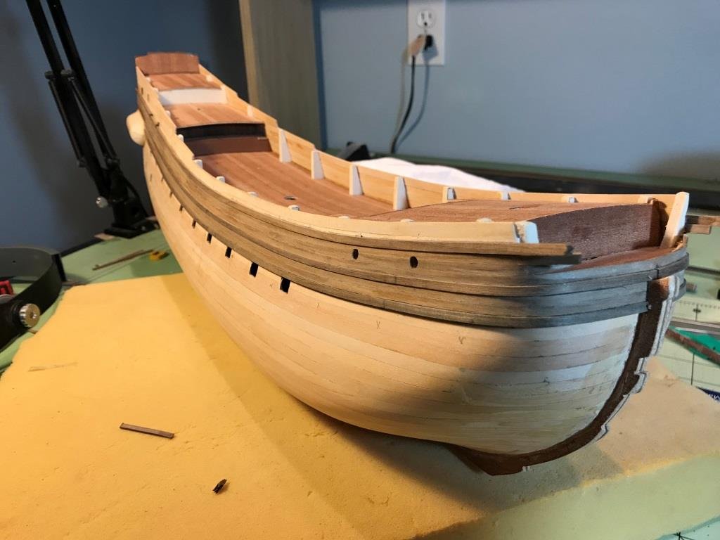
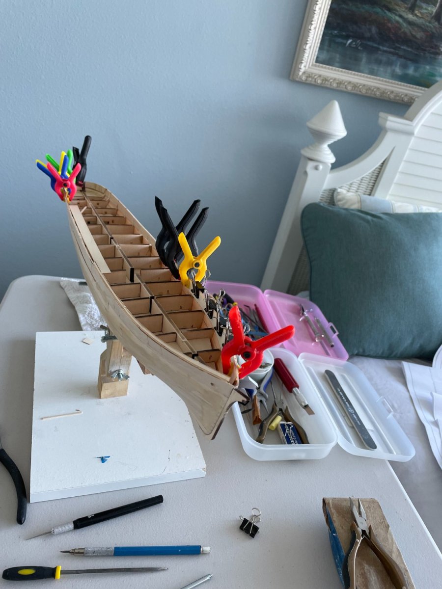
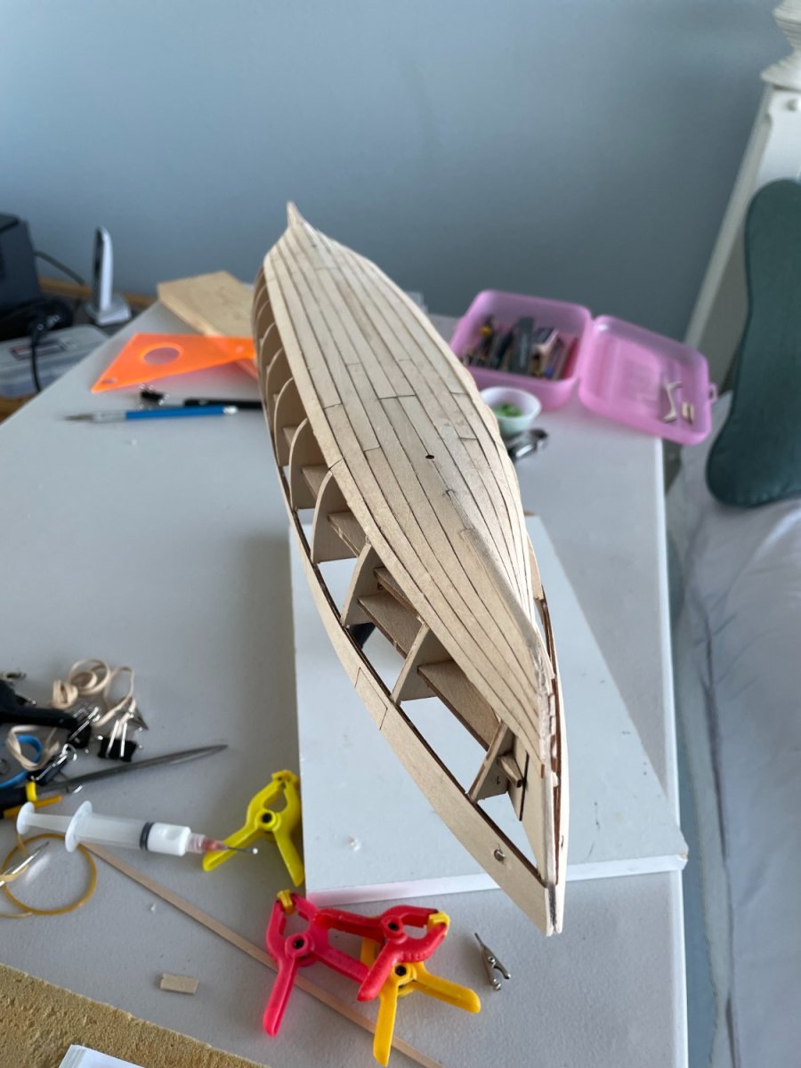
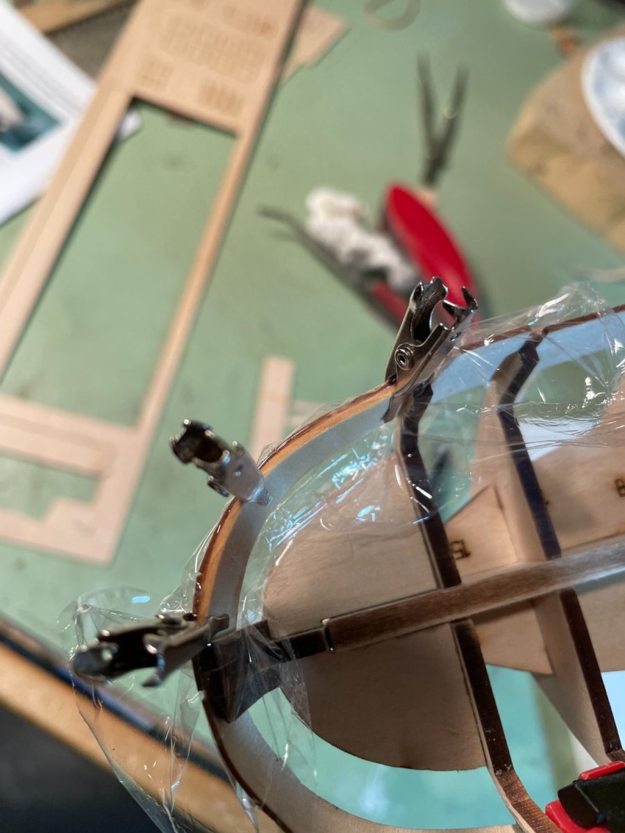
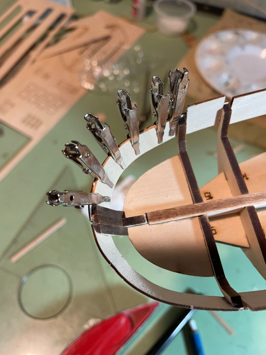
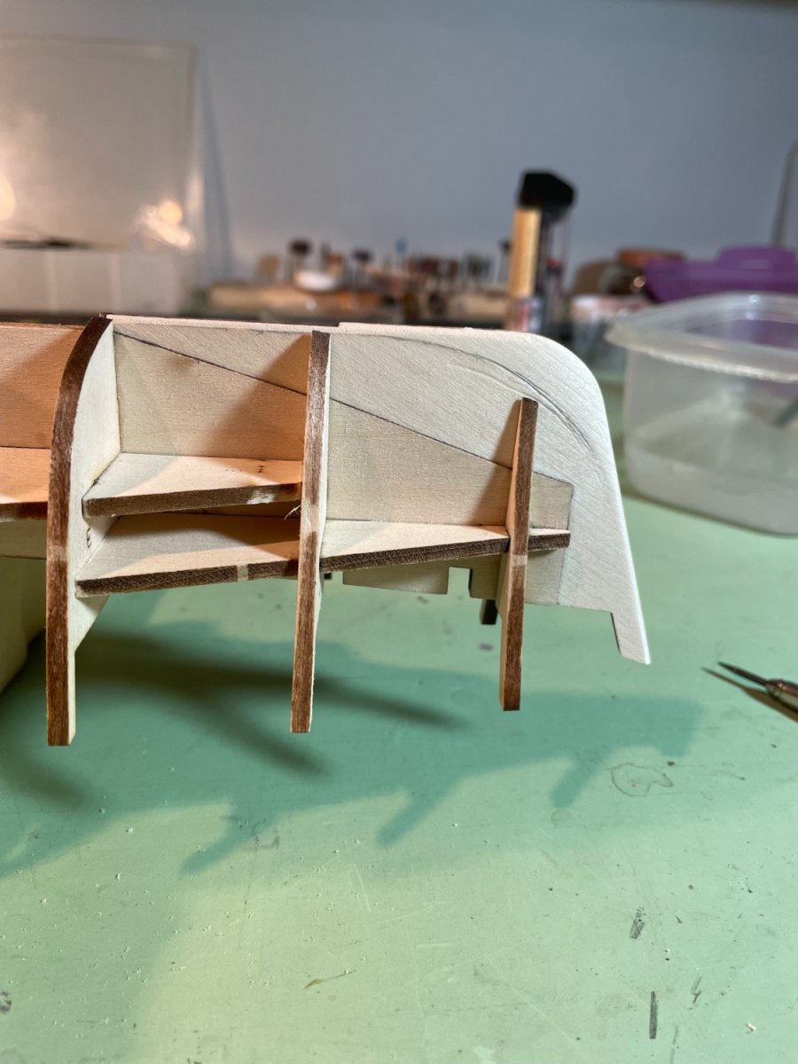
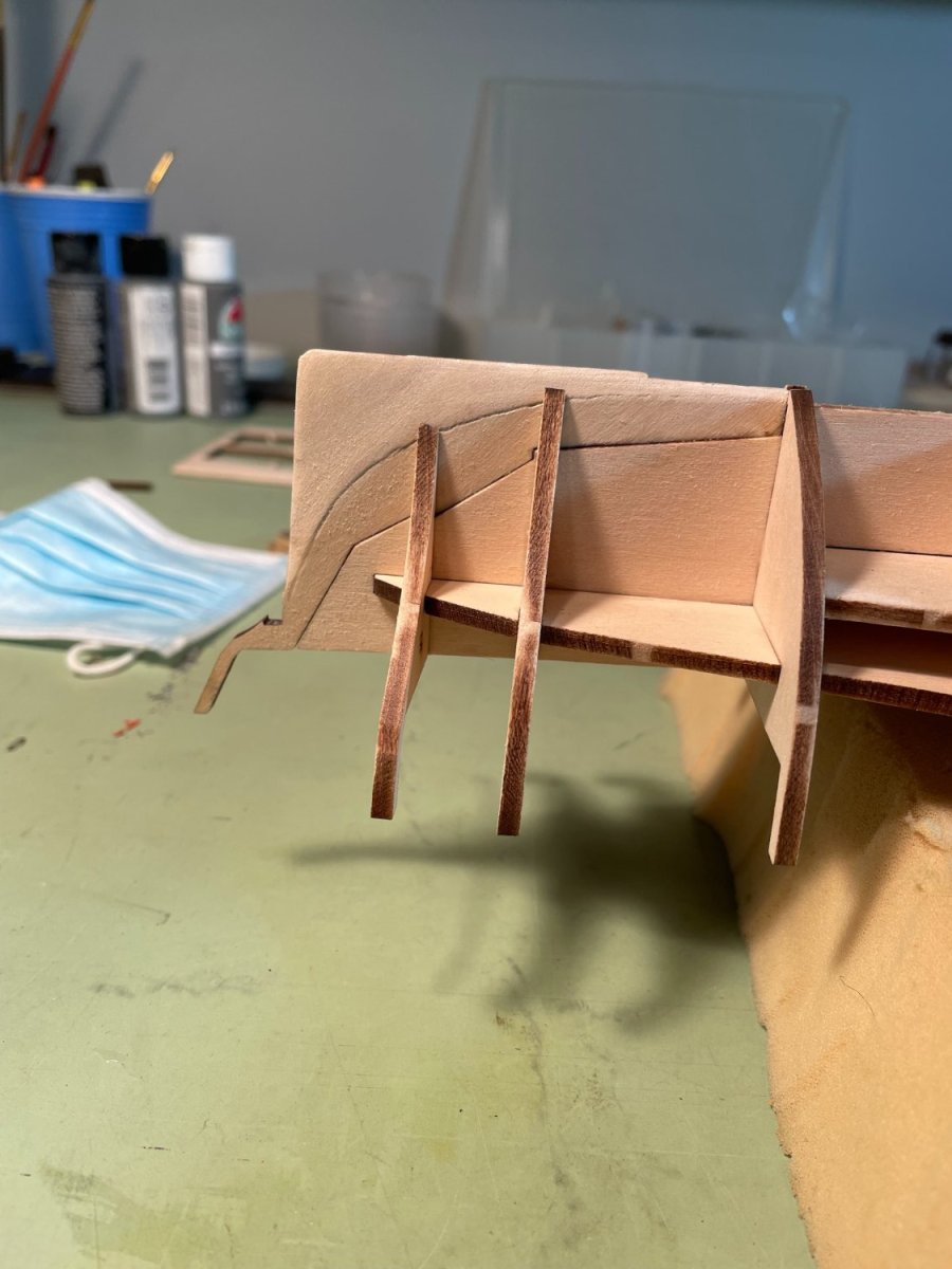
Bulwark inner filling strips:
The straight inner bulwark filler strips were cut to length and glued in between the bulkheads as instructed. For the curved filler strips at the bow instead of cutting each individual piece and then trying to bend them to fit between the bulkheads, I soaked the entire strip of wood and then clamped it to the inner side of the bulwarks. After it dried I cut the individual curved pieces and glued them in.
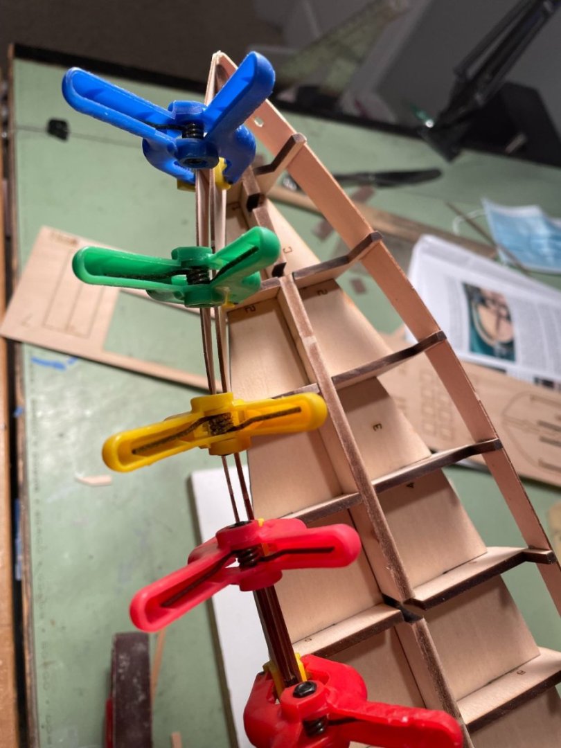
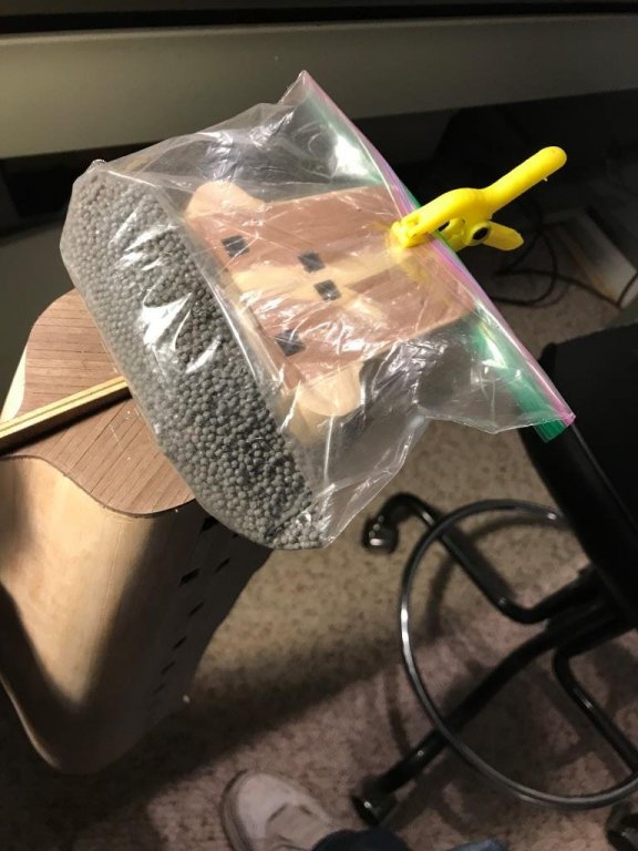
Around the upper counter at the stern the instructions say to use the keystone shaped pieces for the inner filler. I don’t think these were provided or maybe you're supposed to cut them yourself, what I did was to trace the shape of the upper counter on the sheet with the inner filler pieces. After cutting it out it was soaked and formed to fit around the inside of the upper counter. To keep the upper counter from absorbing the water from this piece and possibly distorting it, I placed a piece of saran wrap between the two until the inner piece dried.

After it dried it was glued and clamped in place.

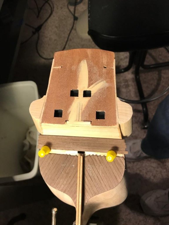
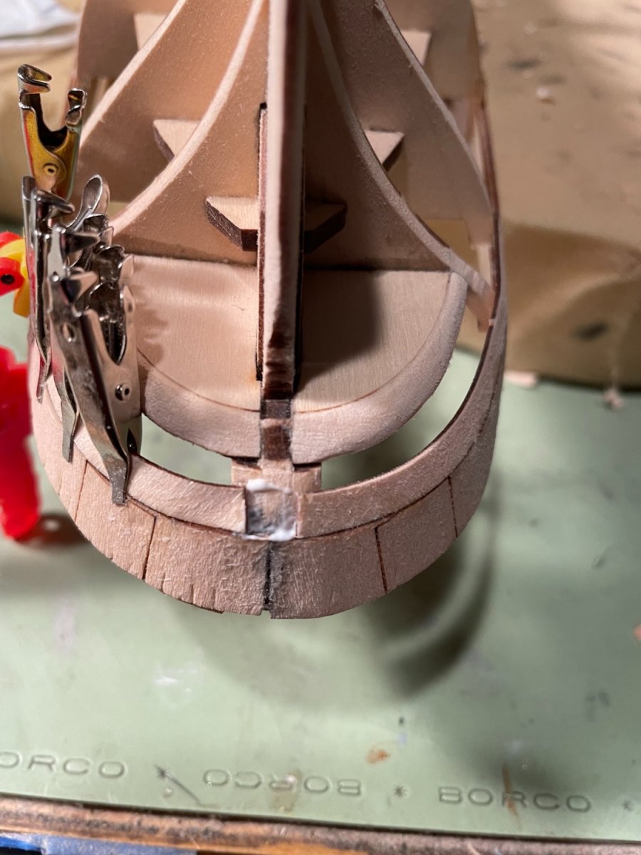
Lower counter pieces:
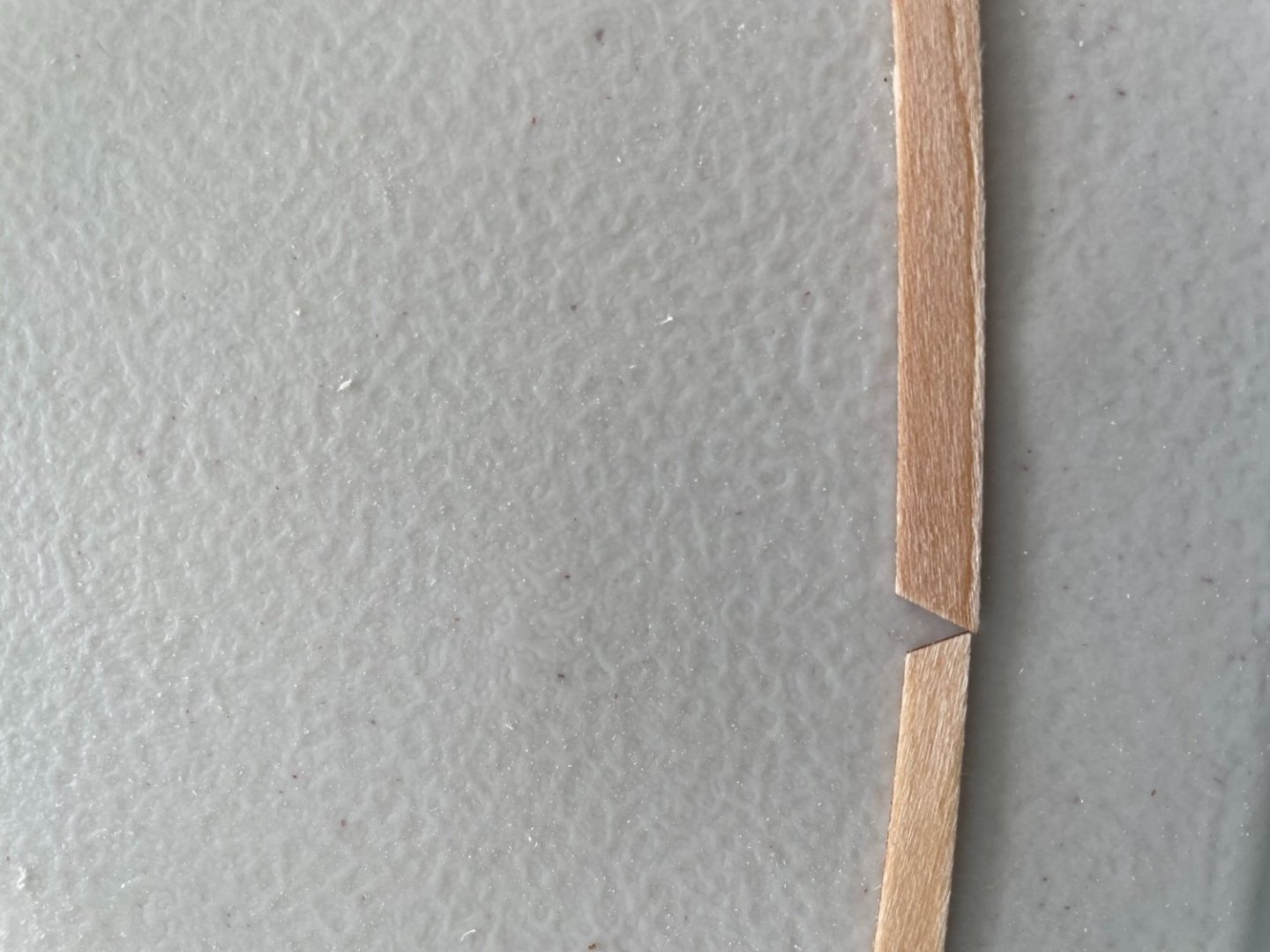
The lower counter pieces were soaked and bent to shape. The pieces provided are a little too short and a small filler piece was fitted between them.

Completed inner bulwark fillers with bulkheads sanded flush to the interior of the inner bulwarks.

- druxey, Canute, Prowler901 and 4 others
-
7
-
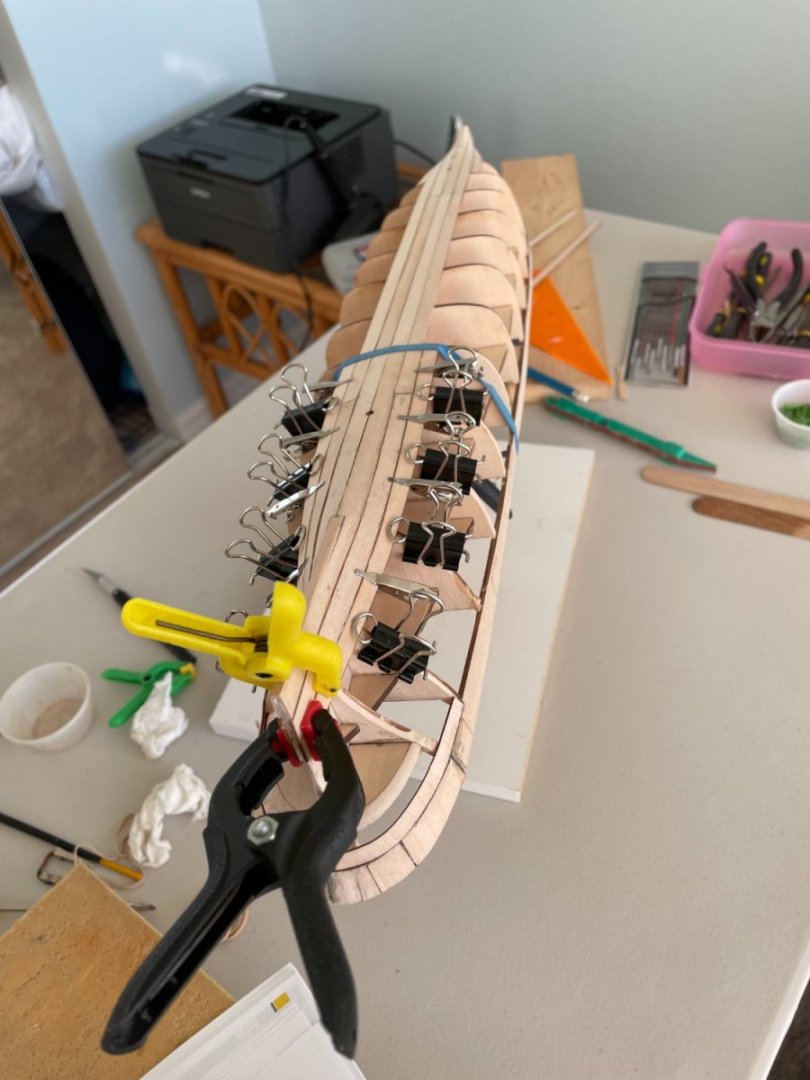
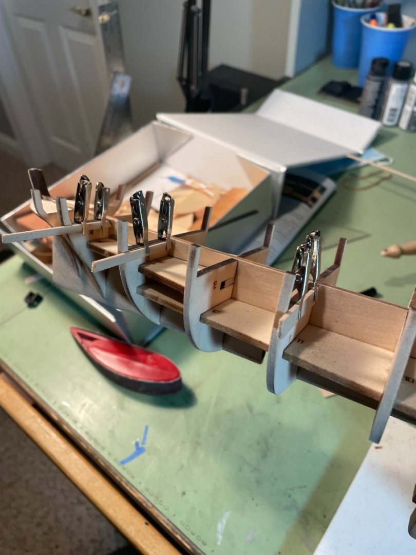
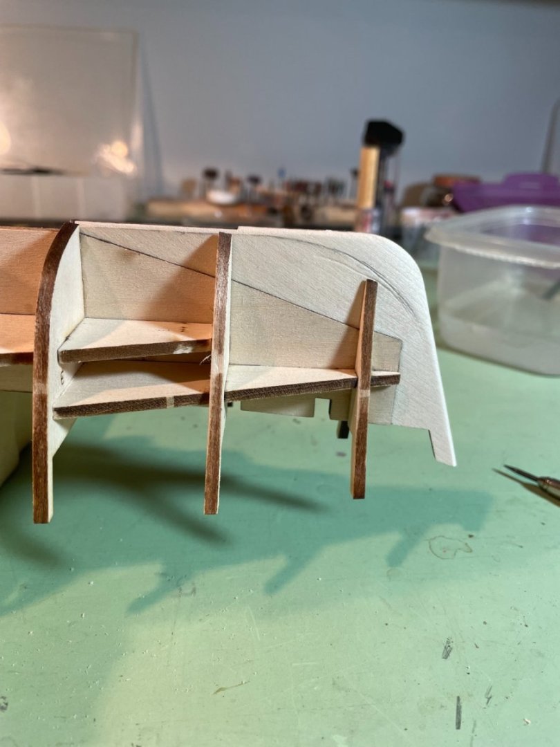
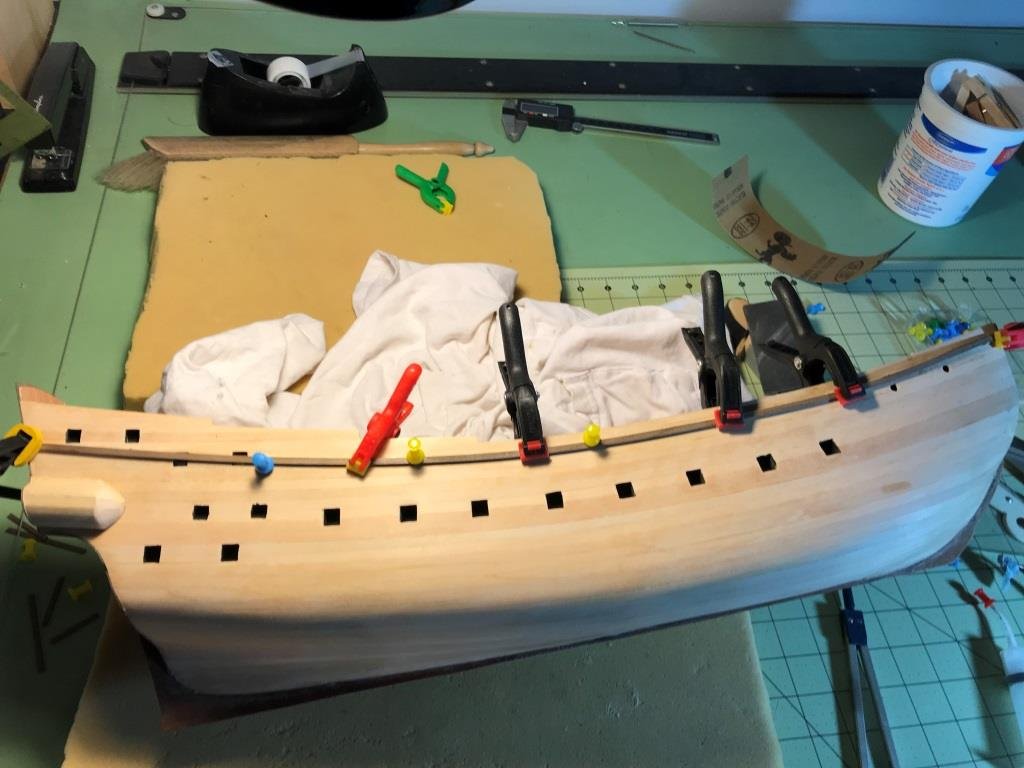
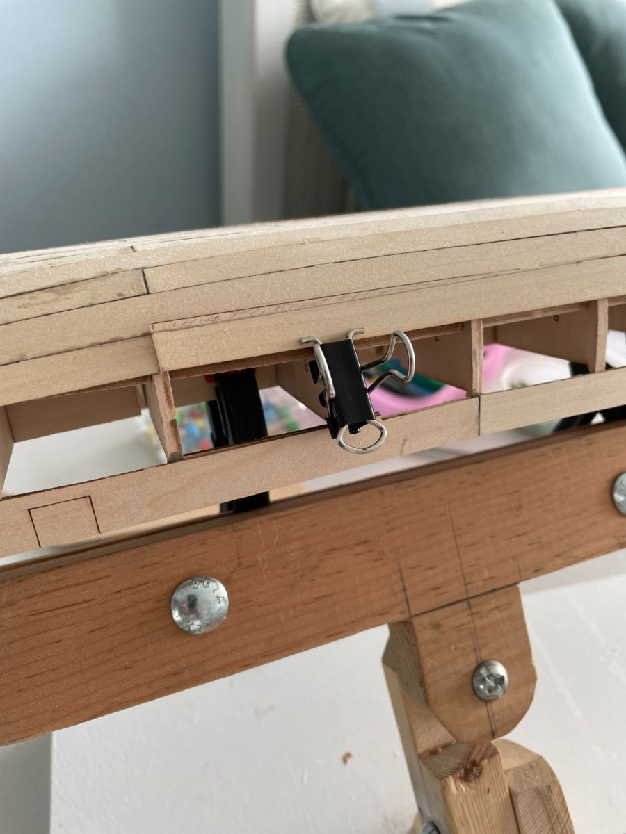
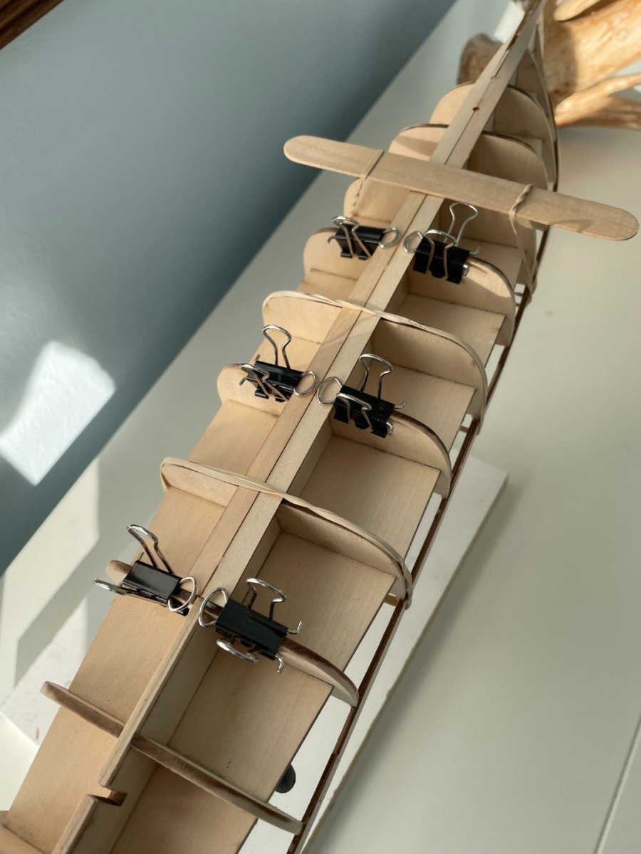
Bulwarks:
The forward bulwark was attached to the bulkheads as shown in the instruction booklet. I found that the wooden strip was thin enough that I didn’t need to soak it in order to shape it to the correct profile.

In order to keep the lower edge of the bulwark even with the top of the deck line on the bulkheads I clamped a few pieces of scrape wood to a few of the bulkheads level with the deck. This helped support the bulwarks while trying to clamp them in place. The picture shows the scrape wood for the aft bulwark. After clamping the bulwark in place I removed the scrape wood so they wouldn’t be glued in place by any excess glue.
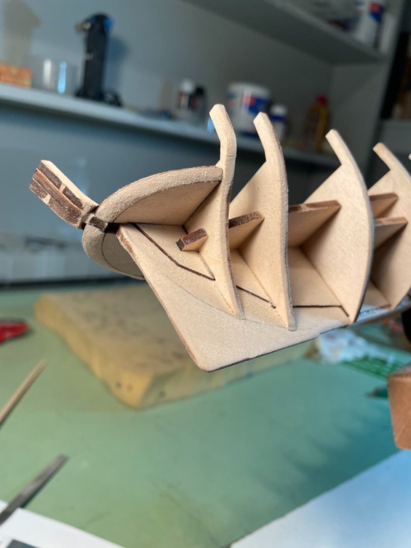
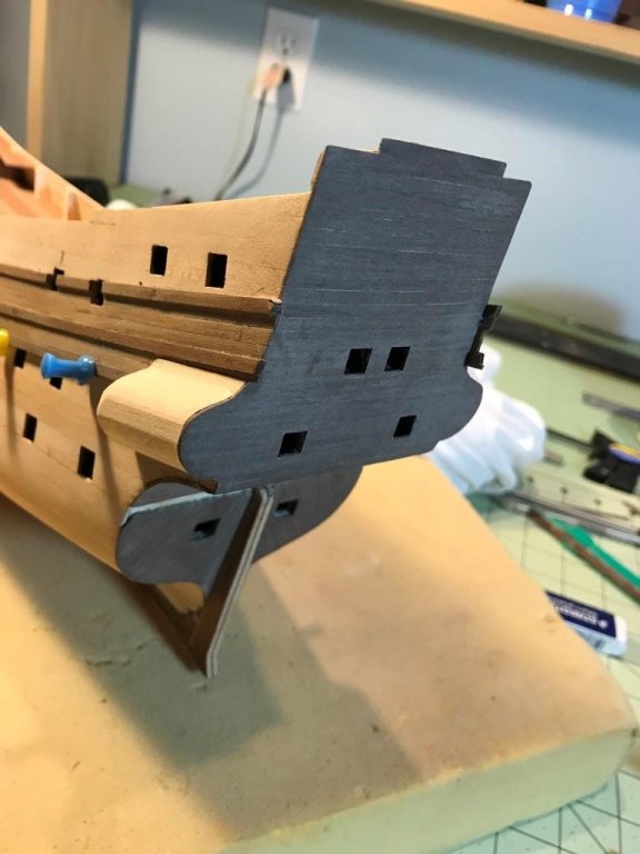
Upper counter:
The upper counter is VERY fragile and needs to be handled with care. The laser etch gun ports in these piece makes them easy to break while trying to bend it. I soaked the counter as instructed and formed it to shape at the stern.

Everything looked good until the next morning when I went to check it and after drying it looked like this.

Fortunately the kit provides two of these pieces. This time after soaking and positioning the counter around the stern I soaked and fitted a piece of scrape basswood in the same shape as the counter to provide some stiffening.
-
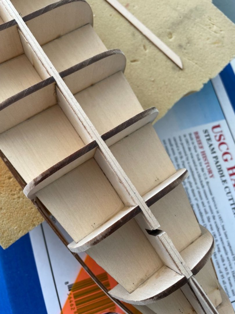
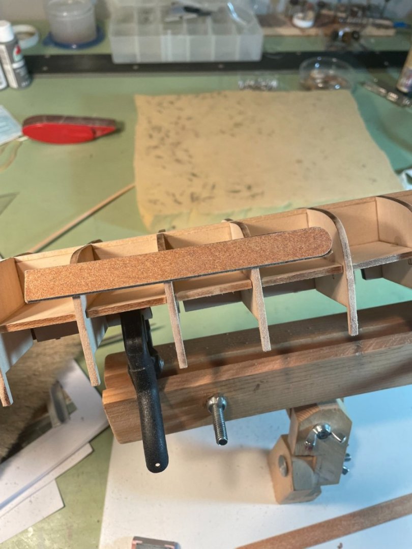
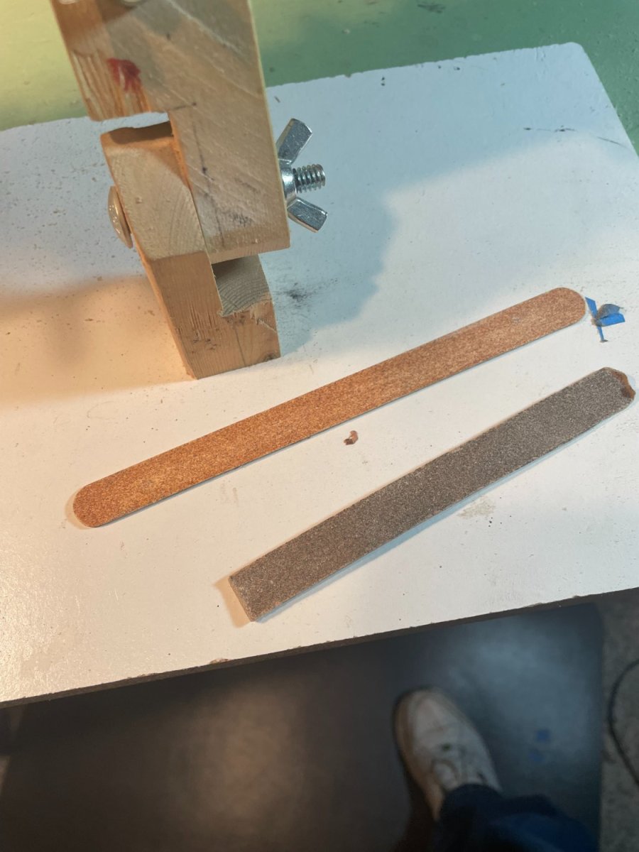
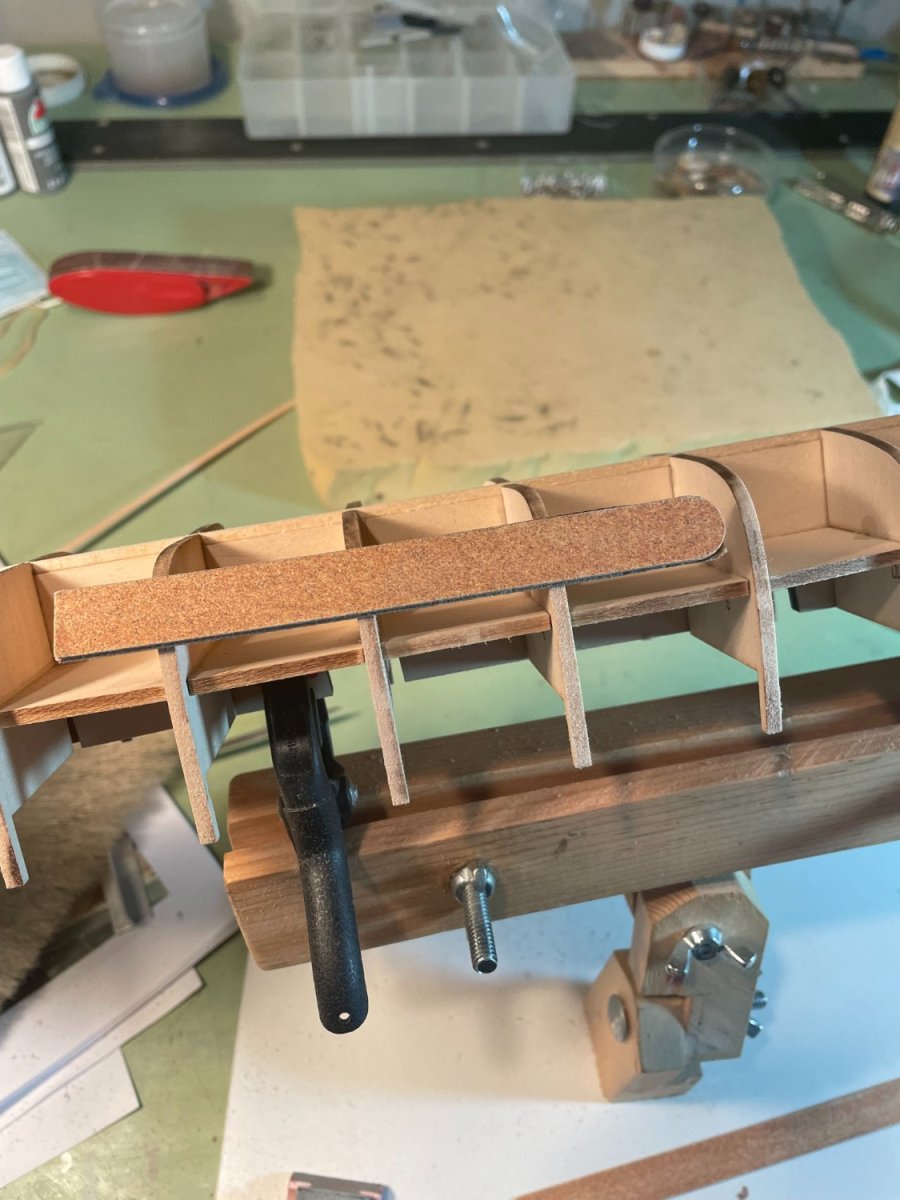
Fairing up the bulkheads:
To fair up the bulkheads I attached a piece of 100 grit sandpaper to and old emery board using double sided tape. This worked well as the emery board was flexible enough to contour to the shape of the hull and stiff enough not to sag between the bulkheads.

-
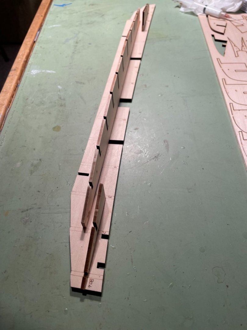
Inner keel pieces:
The inner keel piece is pretty straight forward and was cut and glued in place, leaving gaps for the mounting pedestals.

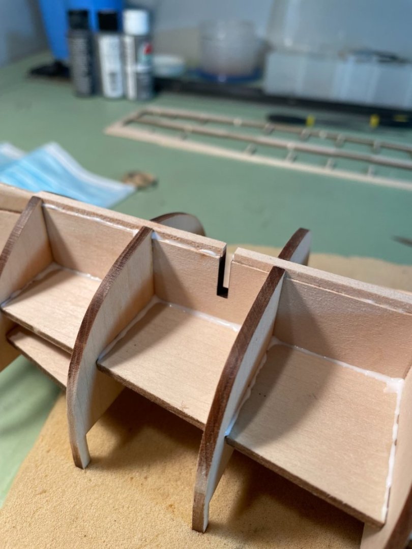
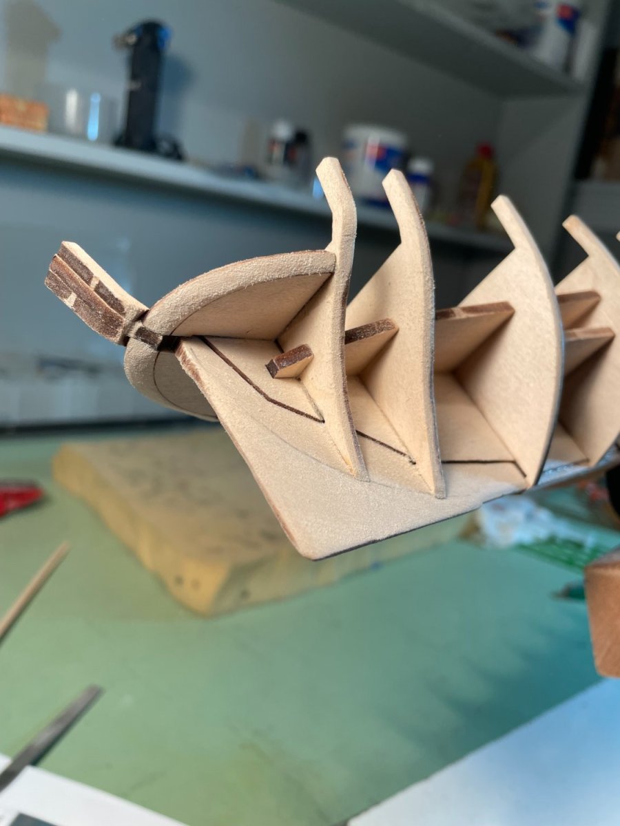
Stern knuckle pieces:
These two pieces were glued into place as per the instructions and then tapered after the glue had dried.
Appreciate the likes, thank you.
-
Hi Bob, just found your new log and will be following along. Things good great so far. Good luck and be patient.
-
First I would like to thank everyone for the likes.
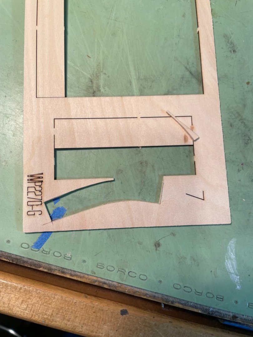
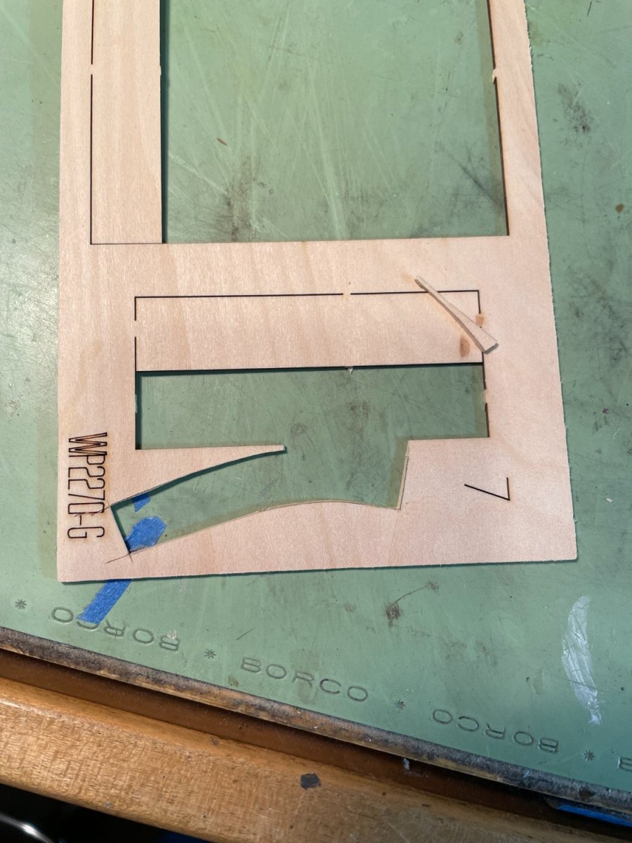
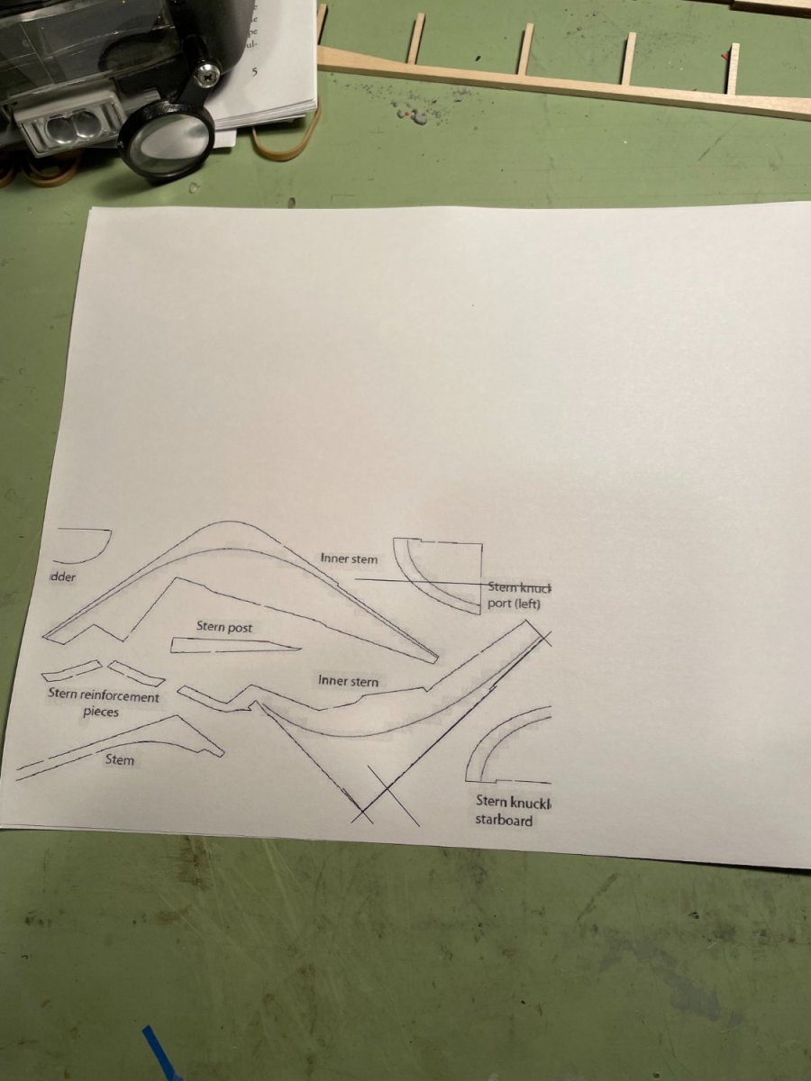
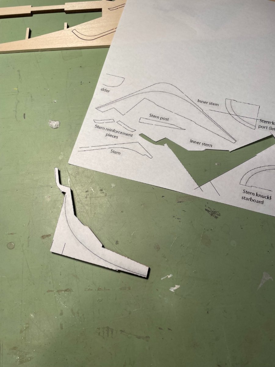
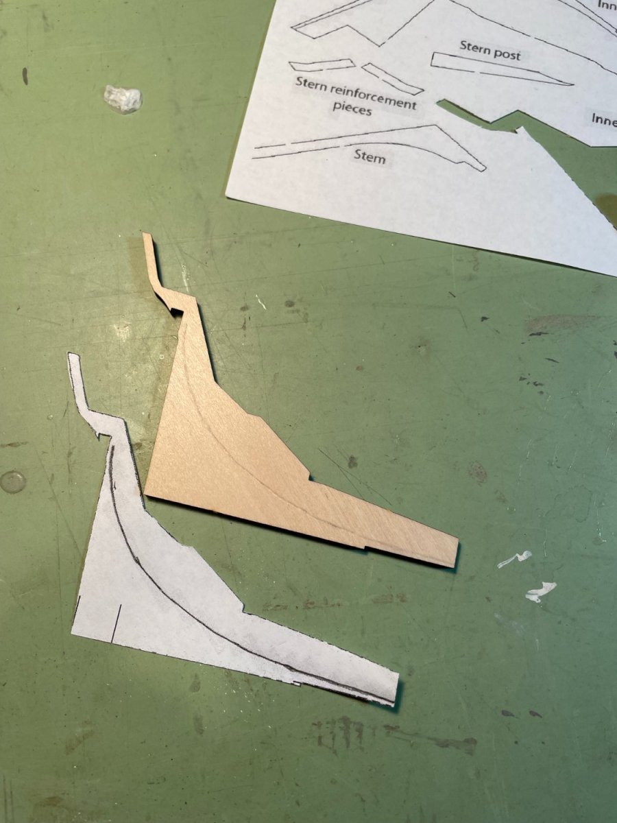
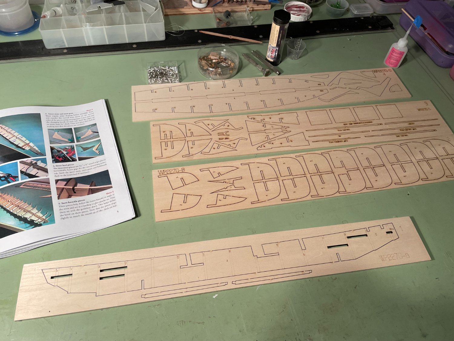
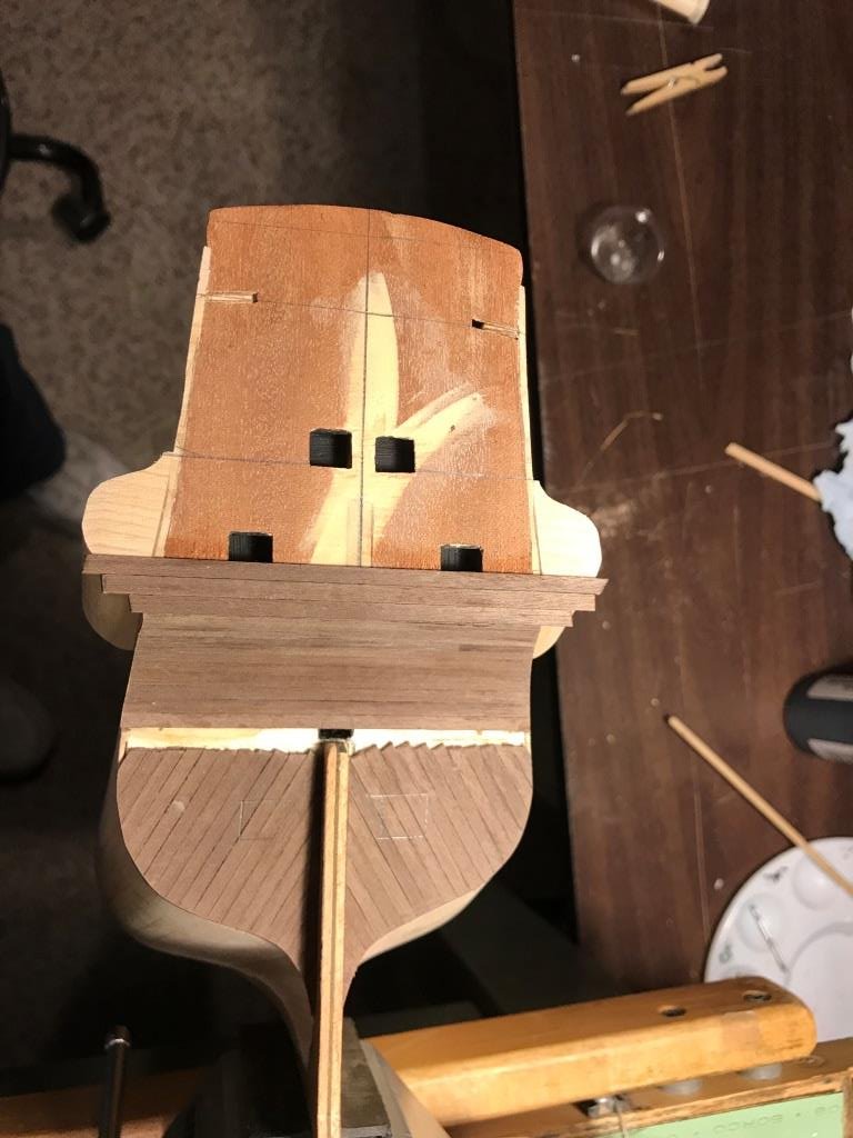
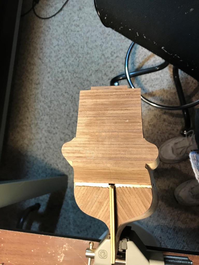
Inner stem and stern post:
The direction call for tracing the curved line (bearding line) onto a piece of paper that was supposed to be laser etched into one side of the inner stem and inner stern post pieces. This line was then to be transferred to the opposite side. However there was no line etched in them. I contacted a fellow MSW contributor, bobandlucy, who had completed this model and whose log I use for reference to see what he used for the curved line. Bob was kind enough to send me an updated parts drawing that he obtained showing the curved line that was supposed to be etched into the parts. Using this drawing I made a pattern of my own that I used to transfer the bearding line to the two pieces.

The back of the pattern was shaded with a pencil and then the line was traced over to transfer the line.


The pieces were then sanded down as called for in the instructions.
Inner stem post
Inner stern post

- Canute, Prowler901, druxey and 3 others
-
6
-
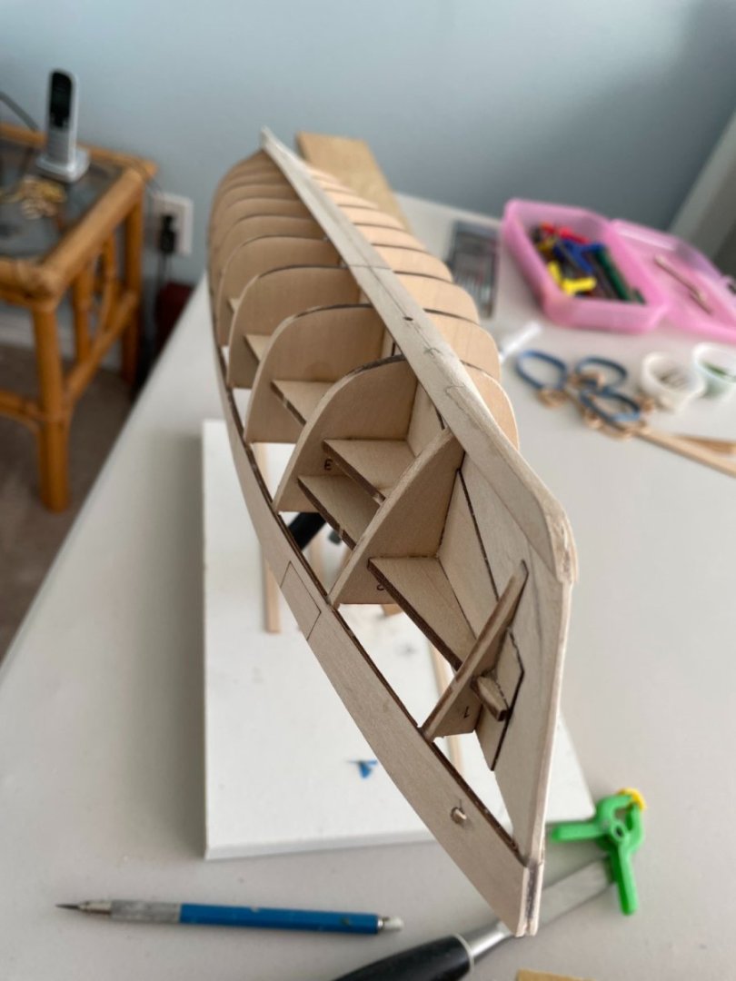
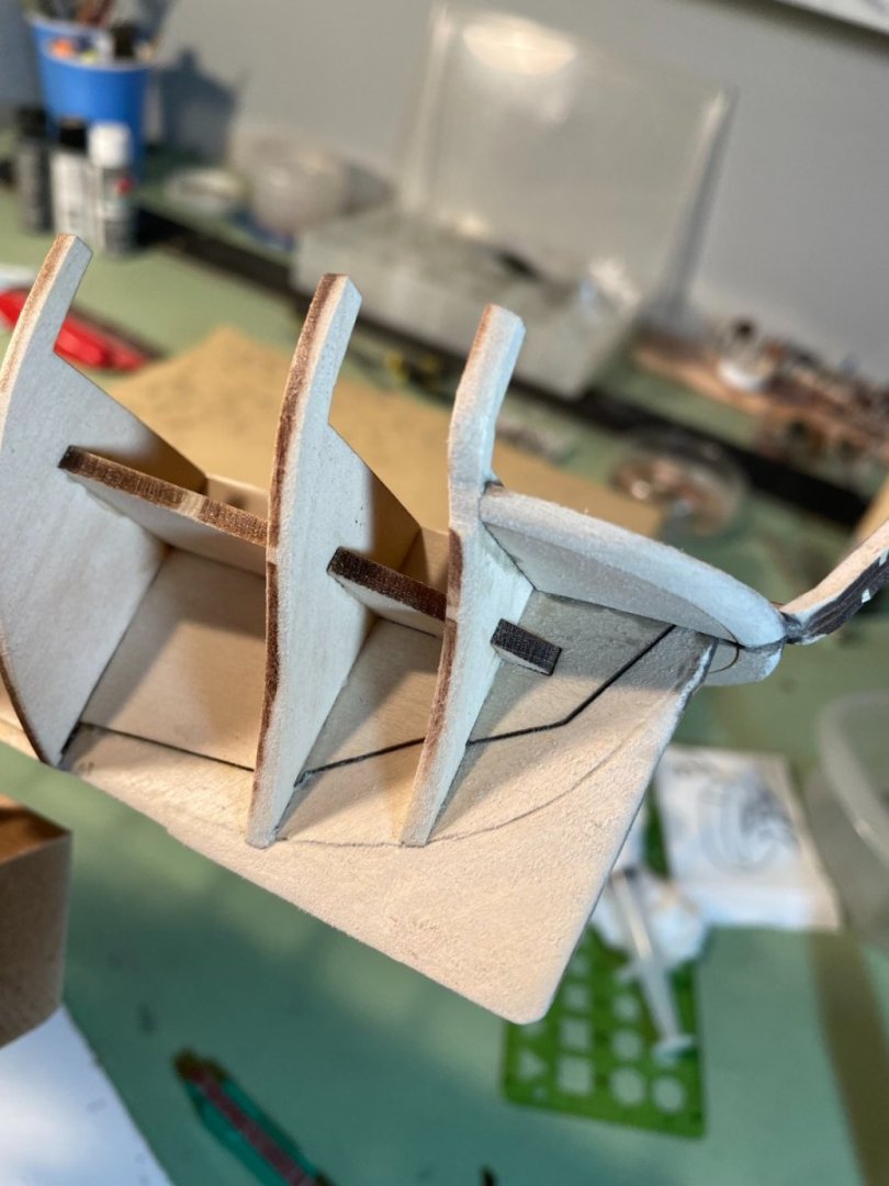
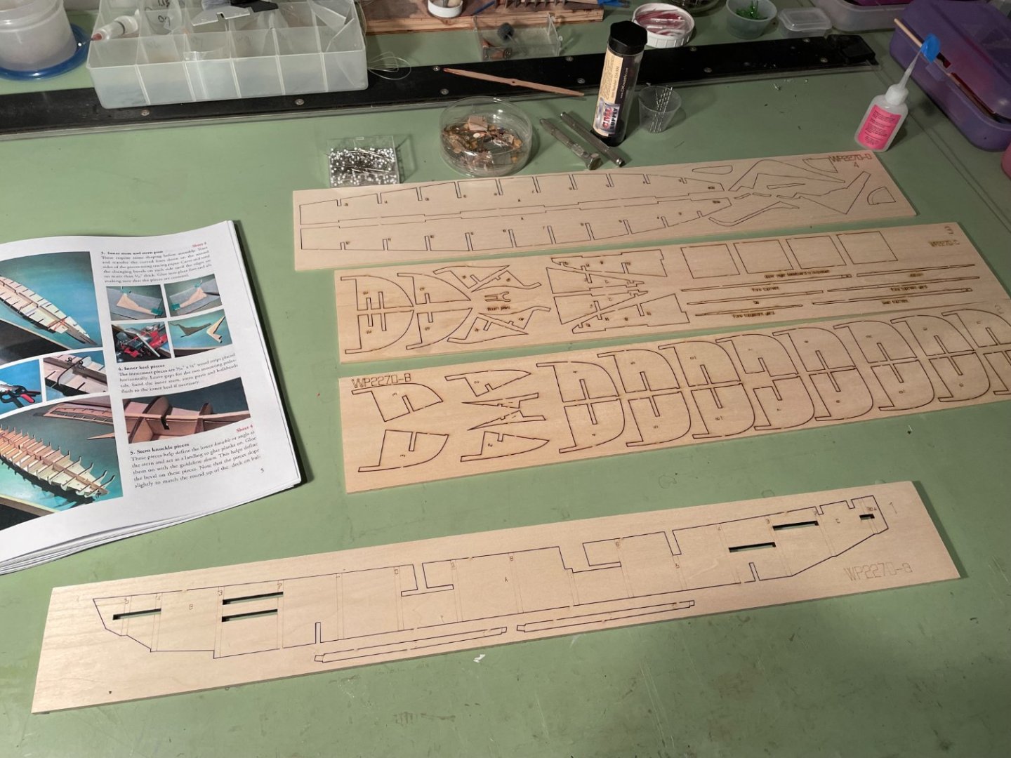
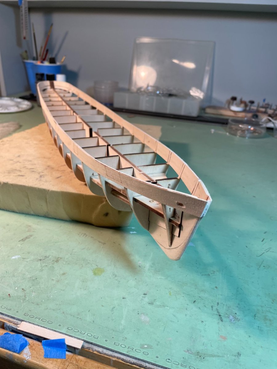
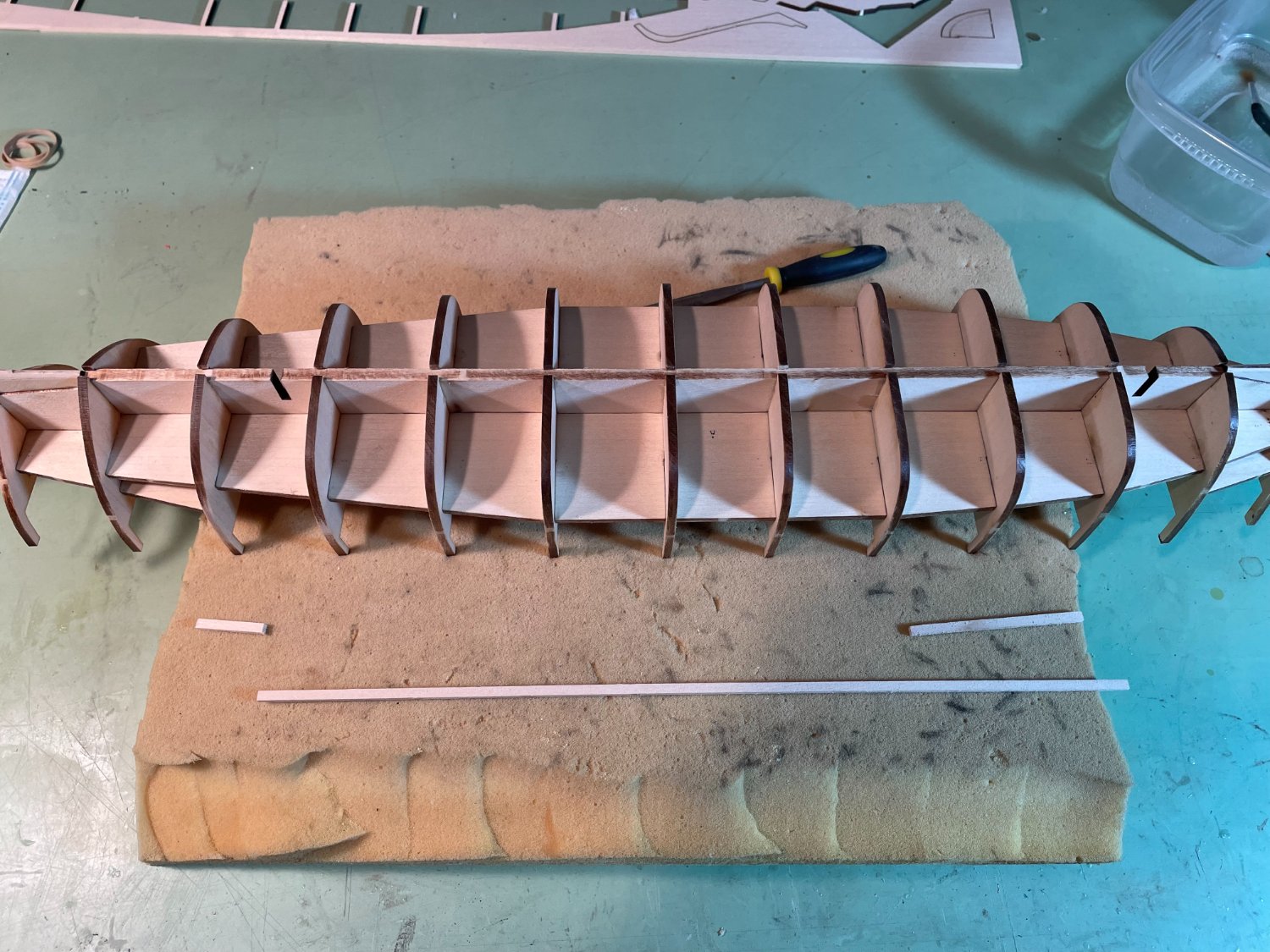
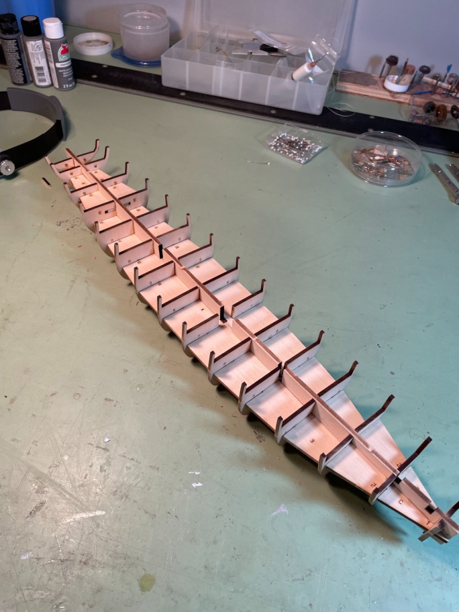
Finished bulkheads.
As a general comment on this kit so far, I found that all the pieces are well labeled so you know exactly where each piece belongs and guidelines are also provided to help with aligning these pieces.

- Prowler901, bobandlucy, druxey and 2 others
-
5
-
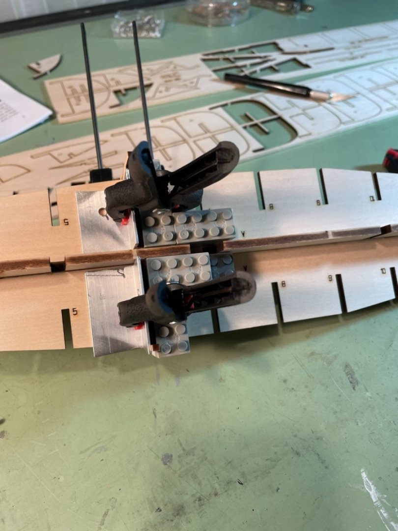
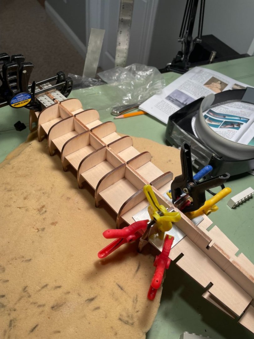
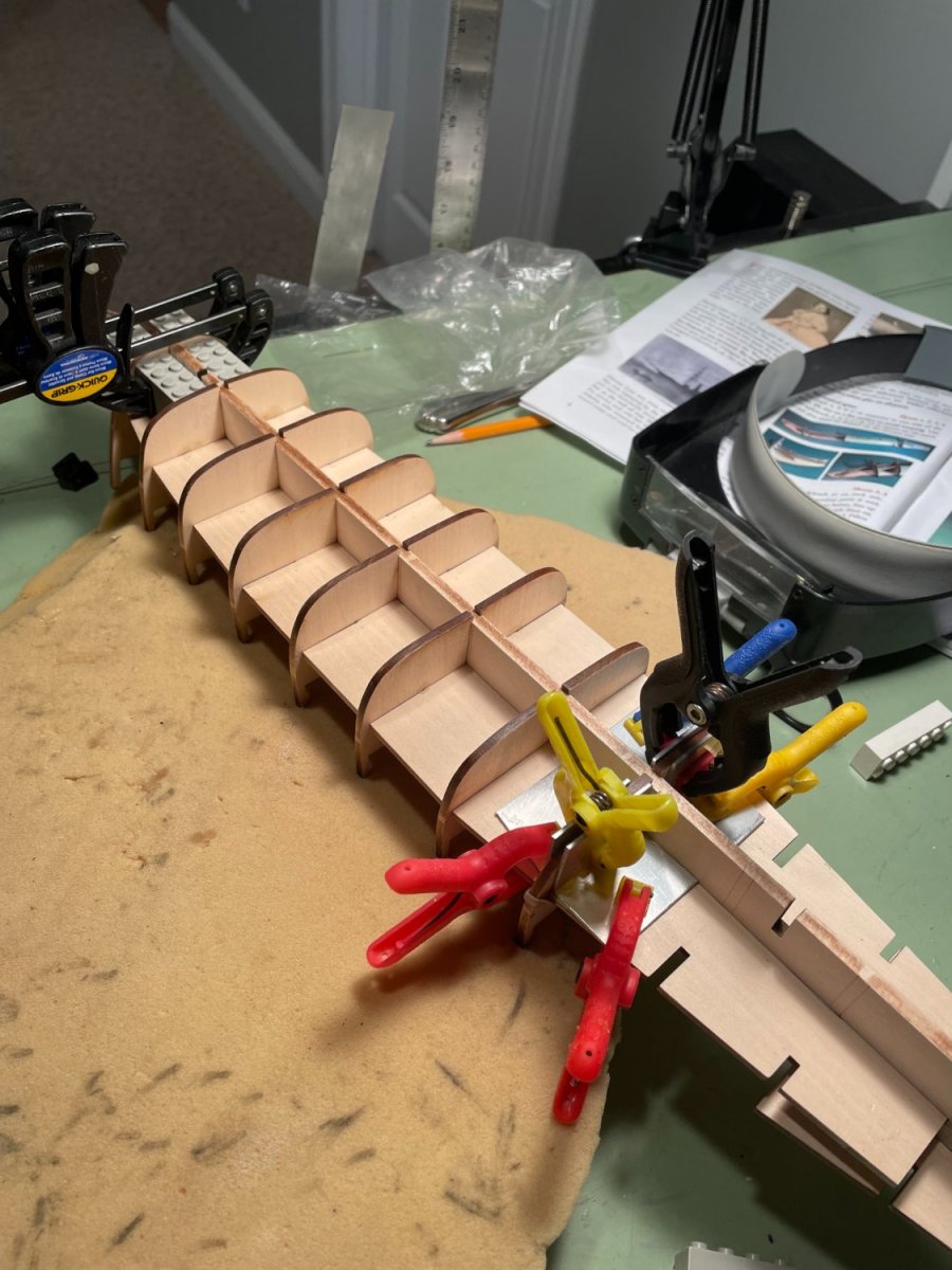
Bulkheads:
After the gluing the bulkhead spacers to either side of the central spine the bulkheads were then glued in place. Bulkheads were squared up using the same combination of Lego’s and the one inch angle. There are guide lines etched into one side of the central spine that helps to align the pieces.
Thanks again for the likes.
-
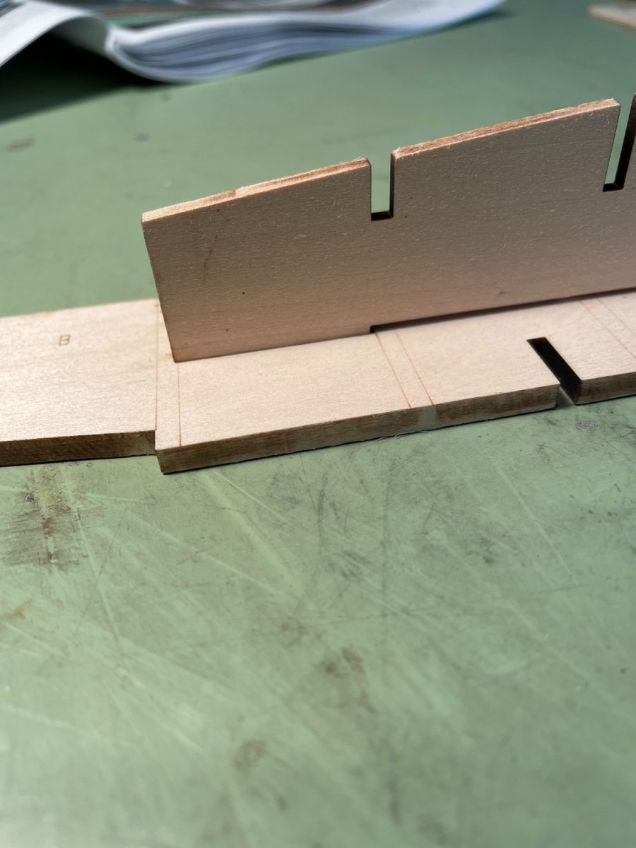
The central spine:
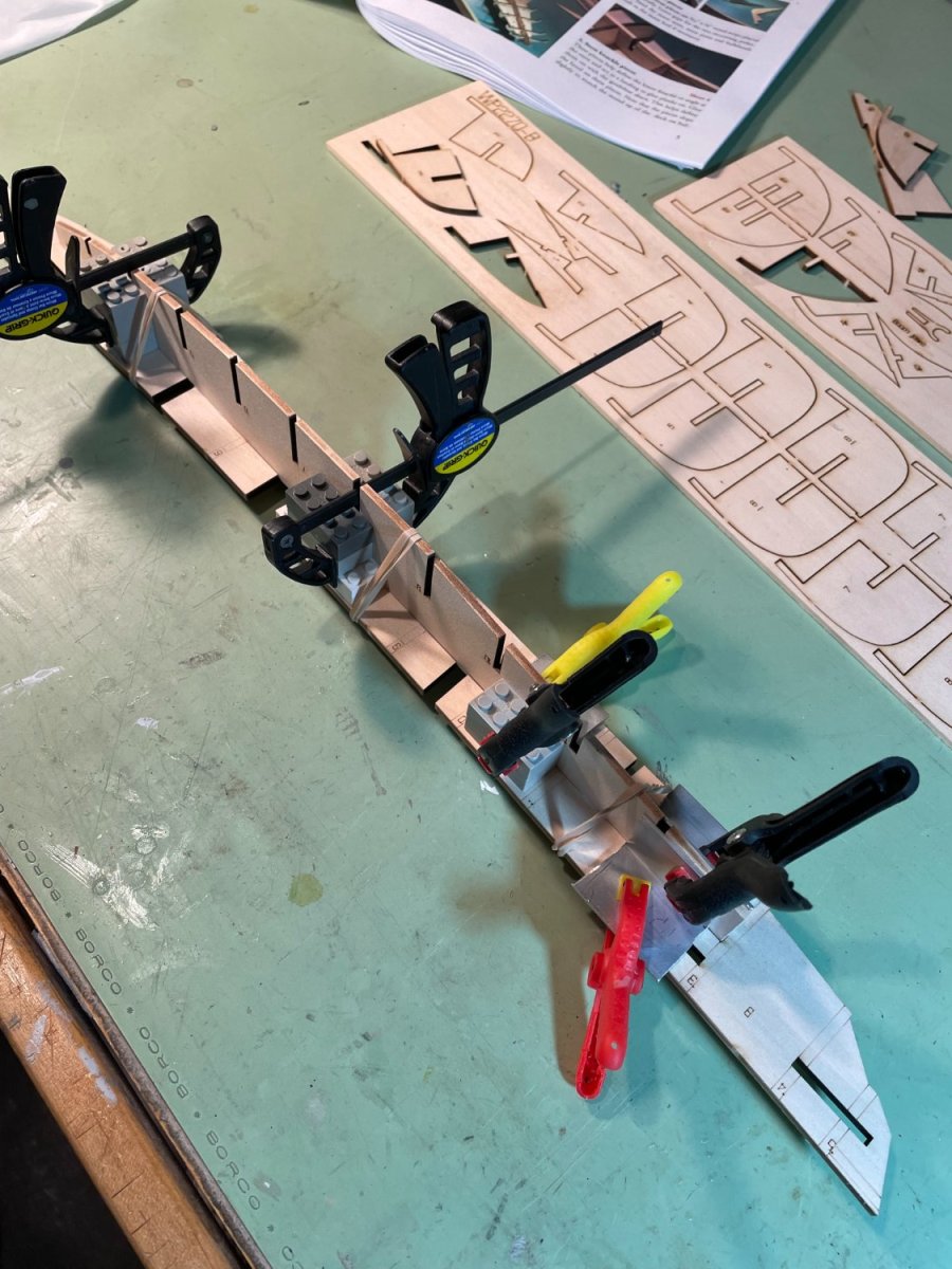
The first task was to glue the bulkhead spacer pieces to the central spine. While dry fitting these pieces it was apparent that the bulkhead spacer’s tabs that fit into slots on the central spine were a little off. A little sanding was required to make them fit.

Although the directions called for the use of the half bulkheads to help square up the bulkhead spacer and the central spine while gluing, I found it easier to use a combination of Lego’s and one inch aluminum angle.

Bulkhead spacers glued to one side of the central spine
- Canute, druxey, Prowler901 and 2 others
-
5
-
-
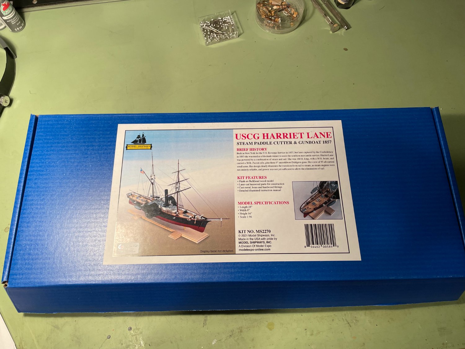
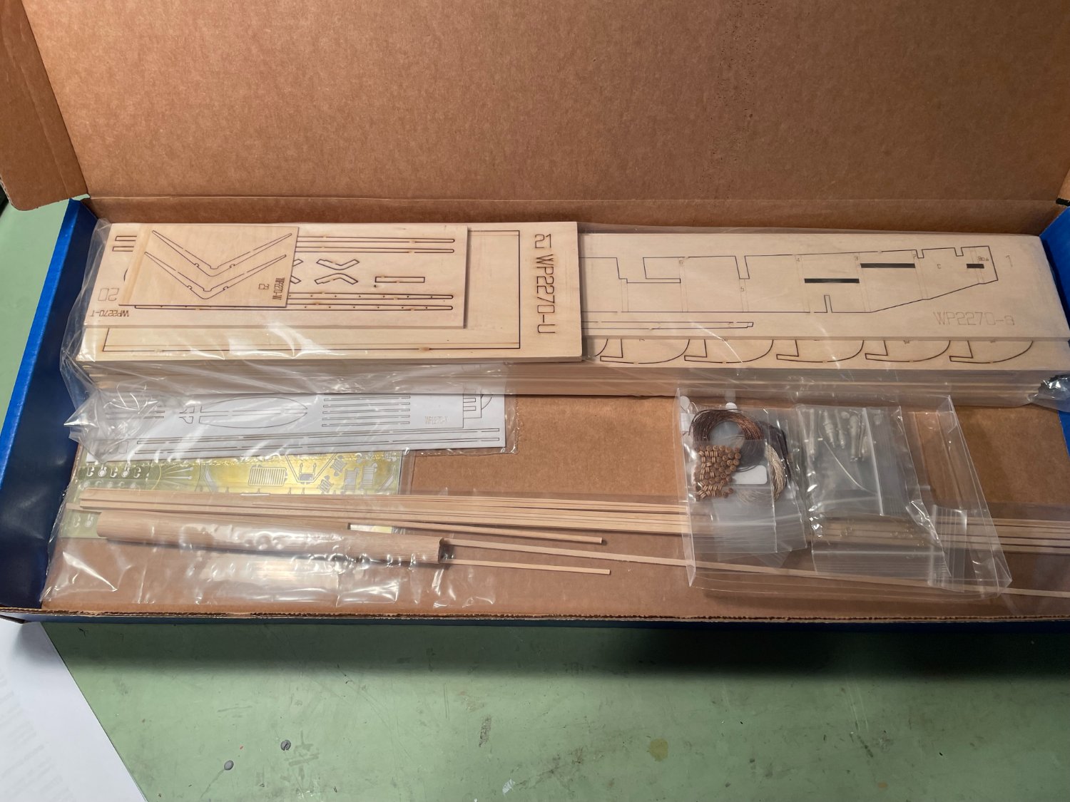
Hello all. I have some time I my hands so I thought I would do a build log of the USCG HARRIET LANE that I got as a Christmas present (to myself). I wanted to try something a little different so the combination of paddlewheel and sails appealed to me. I’ve been away from MSW and the NRG for a few years and had always liked the forum discussions and model postings so I thought I would give it another go. The model’s scale is 1:96 (⅛" = 1' 0") and the overall length will be 28", width 8", height on base 16". The model was designed and instruction book was written by David Antscherl. The kit is from Model Shipways and was purchased from Model Expo. Description of the ship from the instruction book.
The Harriet Lane was 177' 6" long and 30' 6" wide, with a 12' 0" depth in her hold. Her mode of power was provided by double marine steam engines driving two side paddles, as well as two masts for sailing. When launched, her armament was described as ‘light guns’. However, when she joined the West Gulf Squadron her firepower was increased. She was given a 4" rifled Parrott gun and a 9" Dahlgren forward, with two 8" Dahlgren Columbiads aft. Her full crew complement was 95. Launched in November 1859, she was named for the niece of President James Buchanan, who was unmarried. Harriet acted as his First Lady.
Mandatory pictures of the box and contends.


- Prowler901, Knocklouder, druxey and 5 others
-
8
-
-
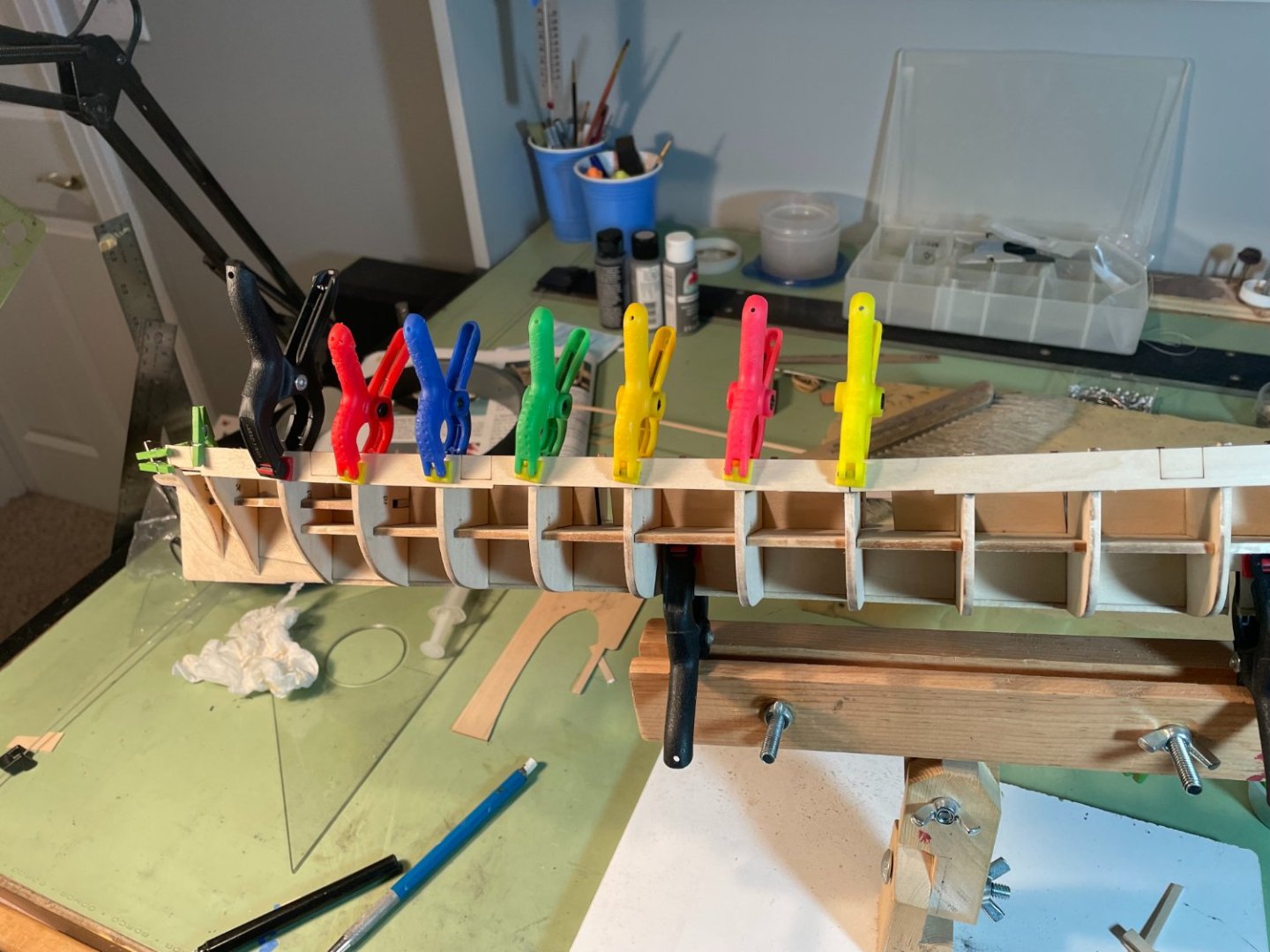
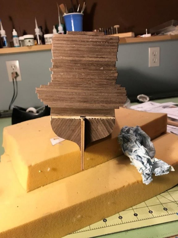
Started on the second planking by laying out the position of the first wale based on the drawings.
After drying overnight I started placing the planking and the other wales. Both sides were planked at the same time.
I also cut out the gun port openings as I went. Not exactly sure on how to finish the planking at the Bow deck so I left it a little long for now.
- bobandlucy, prutser, Landlocked123 and 4 others
-
7
-
Thanks Sjors
Continuing with the stern planking I worked my way up from the curved lower transom to the upper transom.
I used some lead shot to help keep the planking in place while the glue dried.
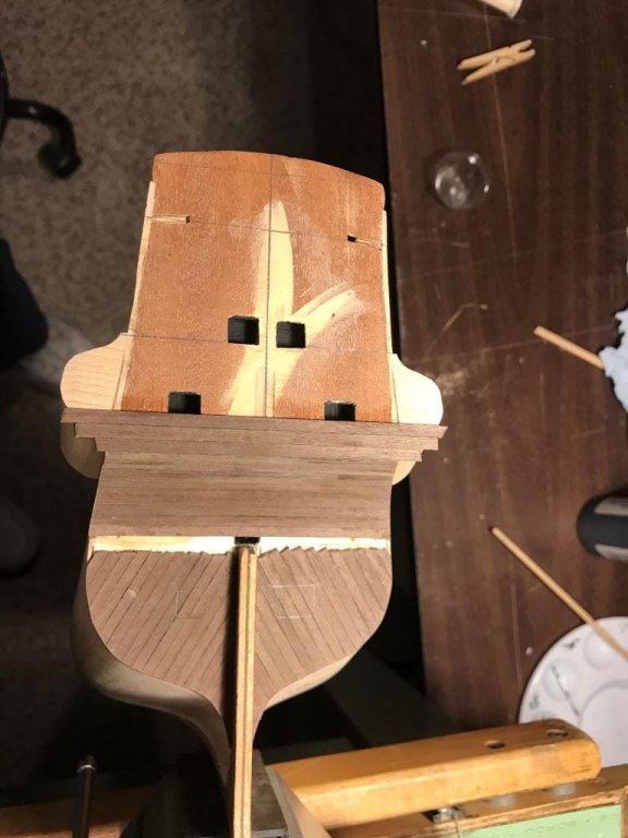
Finished stern planking

I left out some of the planking and the transom moulding because that moulding needs to line up with the main wales along the hull. Once the main wales along the hull are in place I will go back and cut in the transom moulding and finish the planking. I also need to finish shaping the top of the stern transom planking.
- Old Collingwood, Sjors, amateur and 4 others
-
7
-


US Brig Syren by bobandlucy - Model Shipways - 1:64
in - Kit build logs for subjects built from 1801 - 1850
Posted
Nice job on the sills and lintels Bob. Stern is lookin good. I remember the inboard side of the bulwarks were a challenge to sand.
Hope you're all recovered from the cold/bronchitis and good luck with quitting smoking.