


_SalD_
-
Posts
757 -
Joined
-
Last visited
Content Type
Profiles
Forums
Gallery
Events
Posts posted by _SalD_
-
-
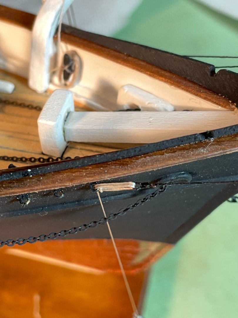
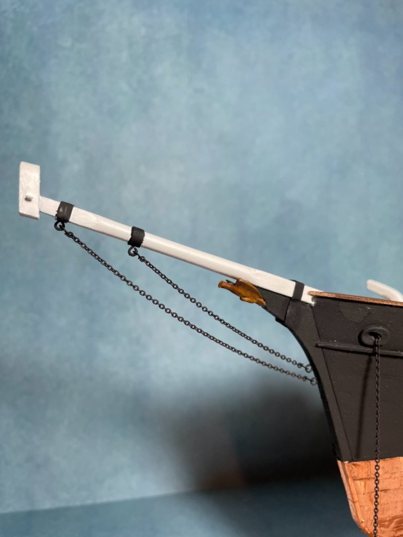
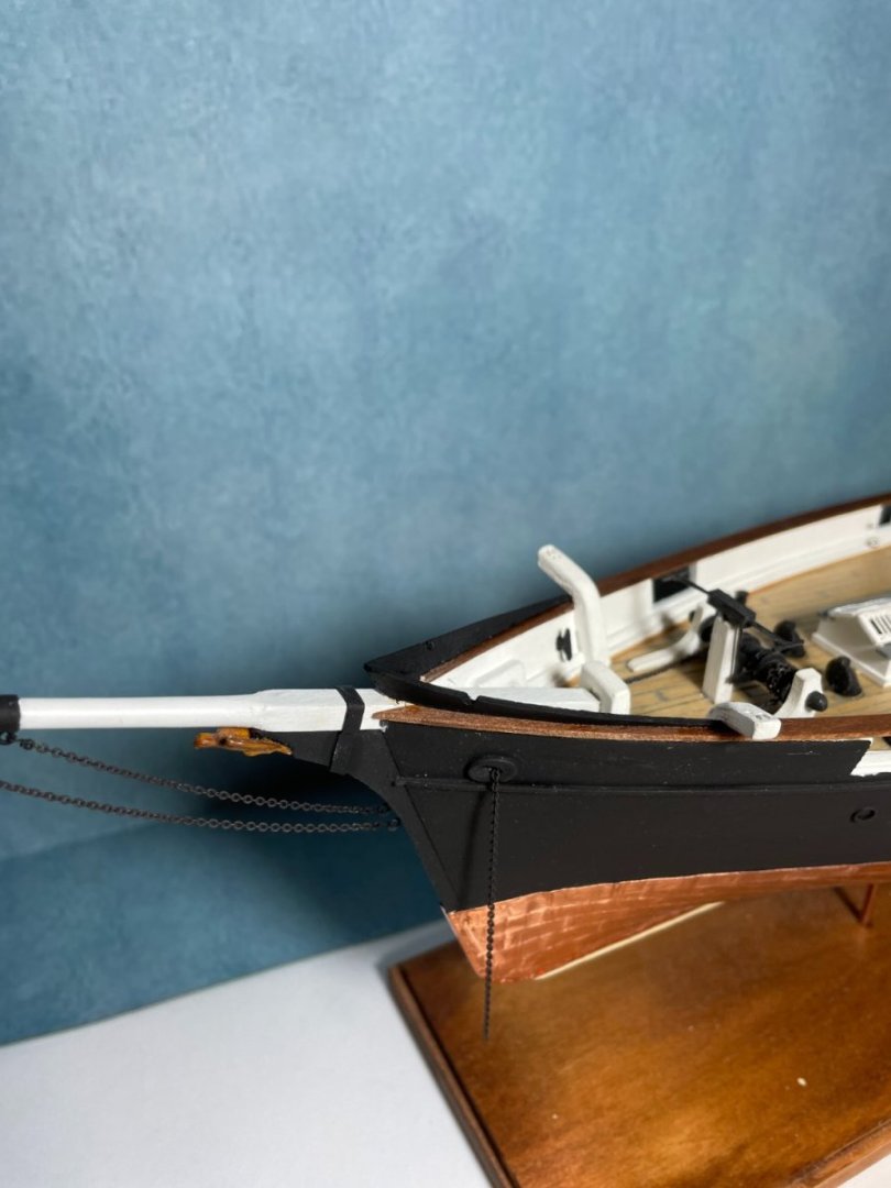
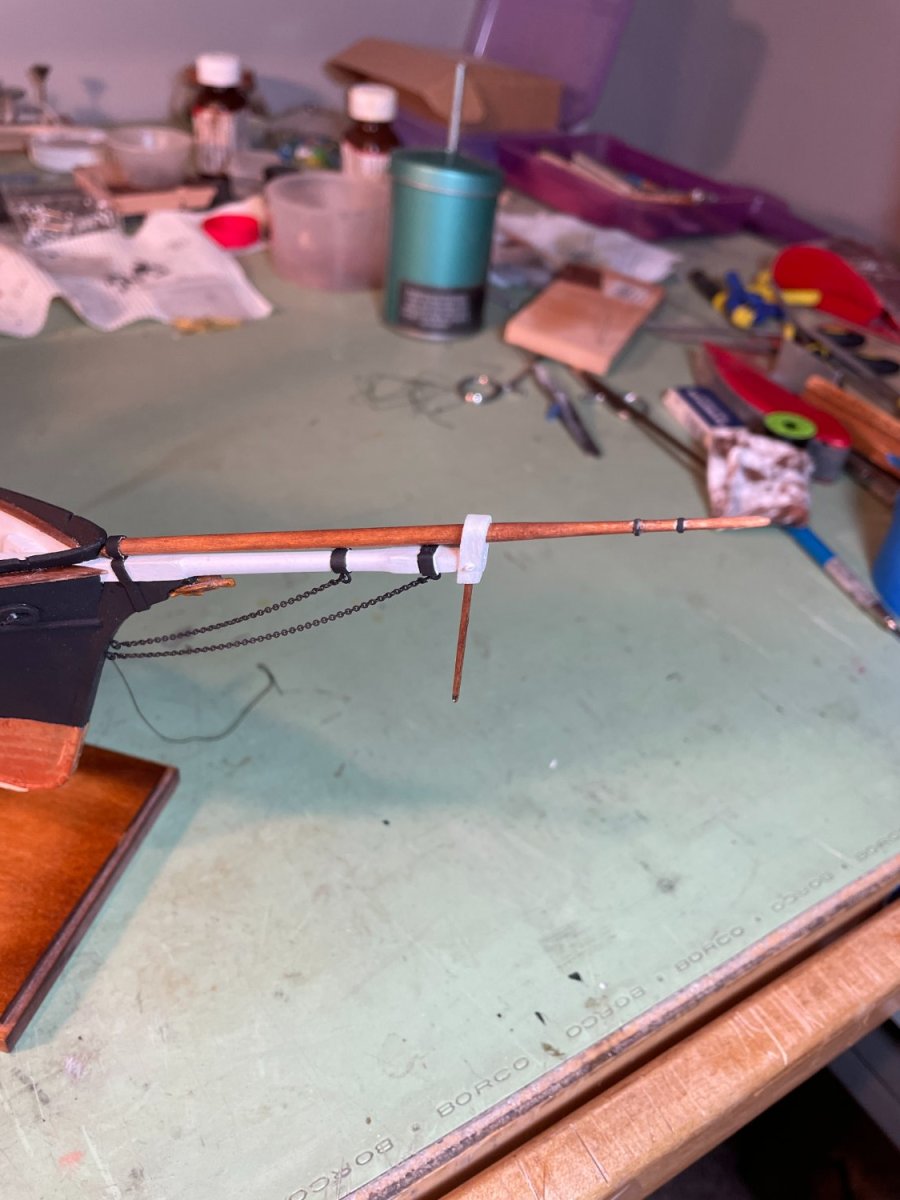
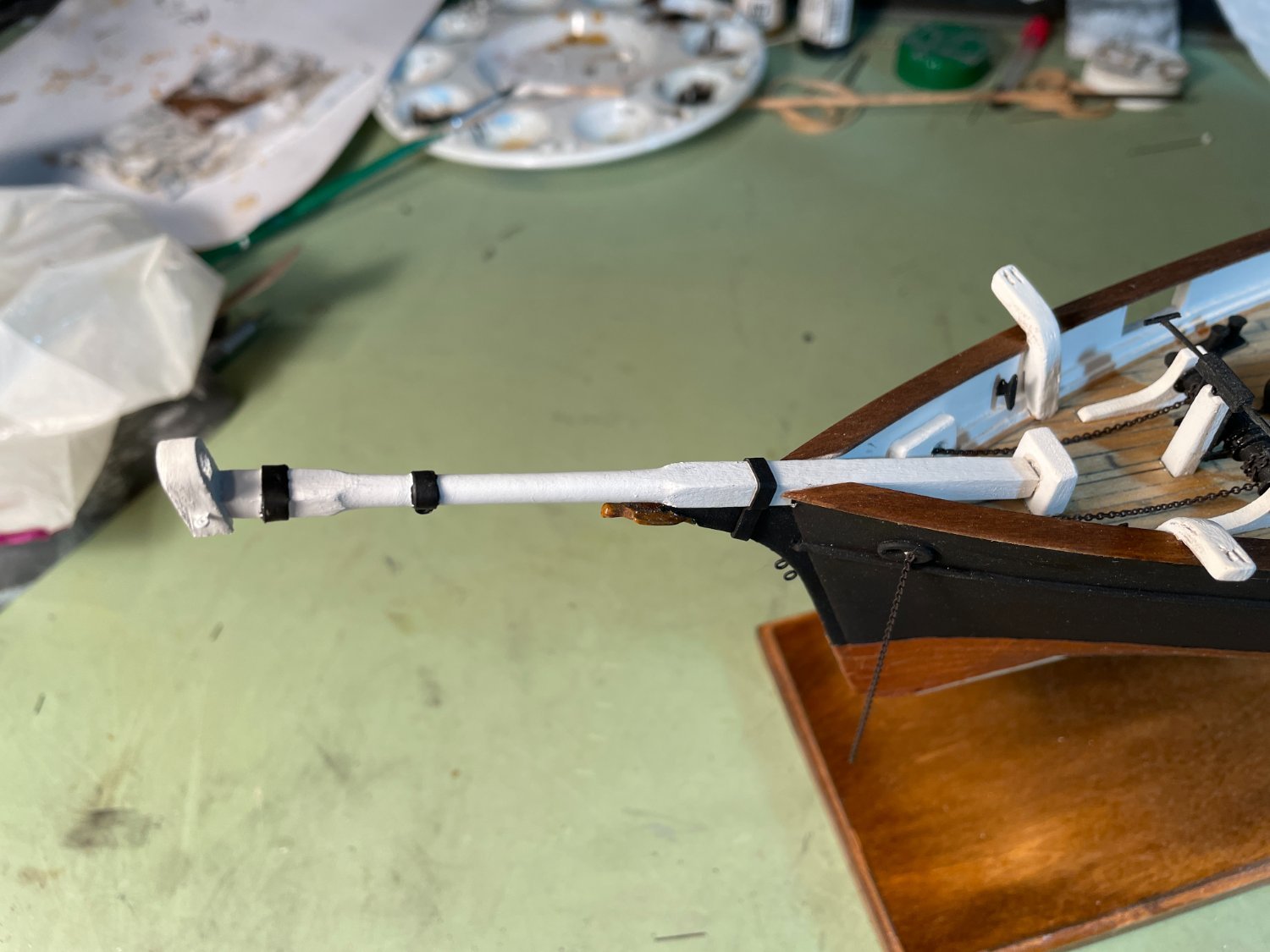
The jibboom and striker were installed so now I have something to break off. I think I broke the striker off my Syren three times while I was building it.

I added an additional gammoning strap made of card stock to secure the jibboom.

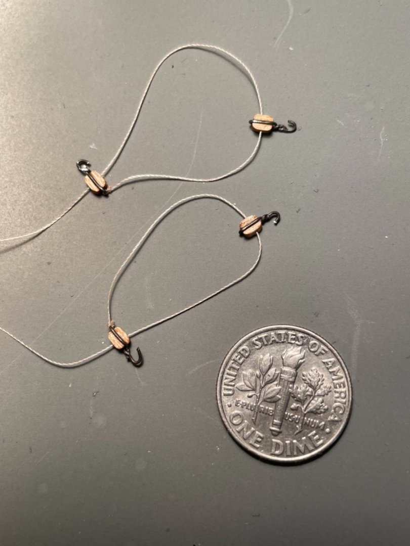
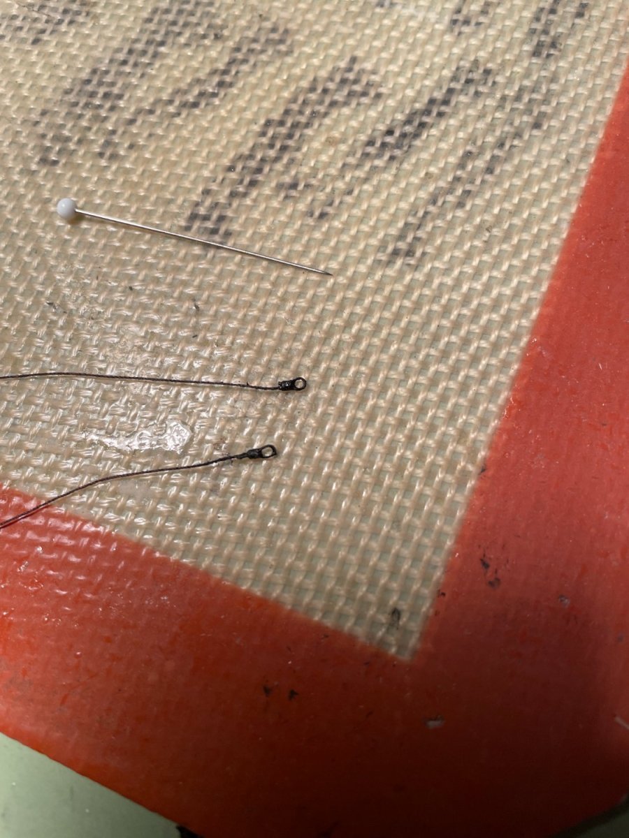
For the bowsprit rigging I decided to try the super detail mentioned in the instructions to simulate the lanyards at the inner end of the stays and shrouds. To do this I first siezed an eye loop at the end of the stays and shrouds, stiffened with ca glue.

After attaching the outer ends of the stays and shrouds to the jibboom and cap I connected the inner end to the eyebolts attached to the bow by lacing thread through them and the stiffened eye loop. (I think it's time to dust my ship)
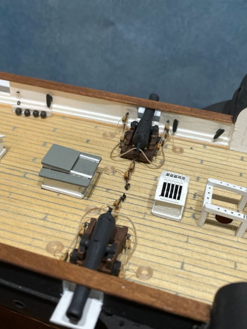
Completed bowsprit rigging
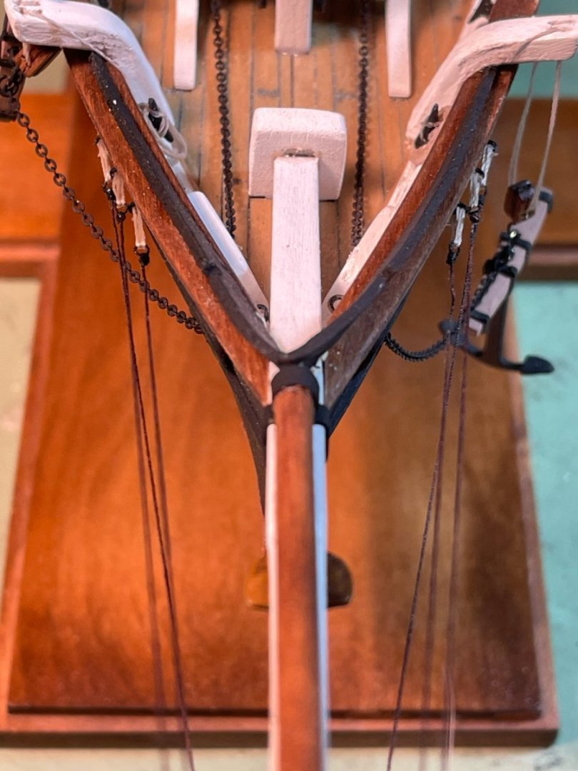
Note: I found it very hard to keep the rigging for the martingale stays under the pin at the bottom of the striker while tying these lines. Maybe I didn't make the pin long enough.
- bobandlucy, druxey, ccoyle and 2 others
-
 5
5
-
-
The jibboom, gaff, boom and striker were all sanded down according to the plans as were all the yards. Eyebolts and card stock were added where called for. All the pieces were stained and the mast heads were painted white.
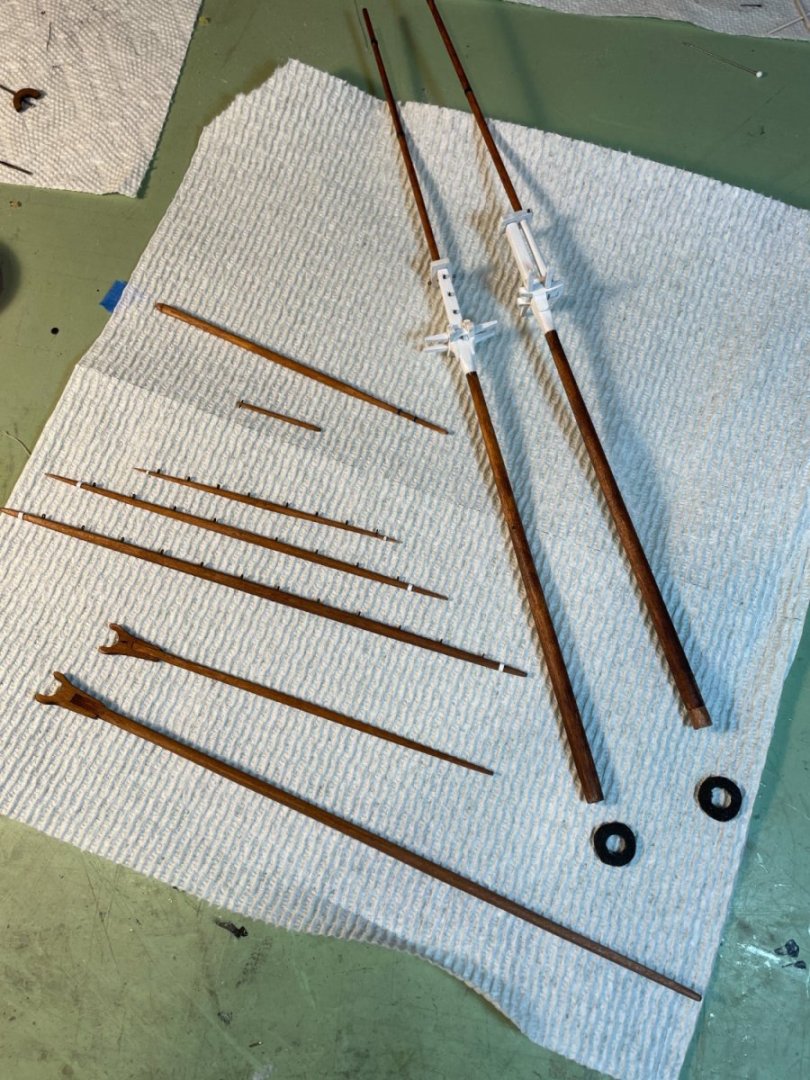
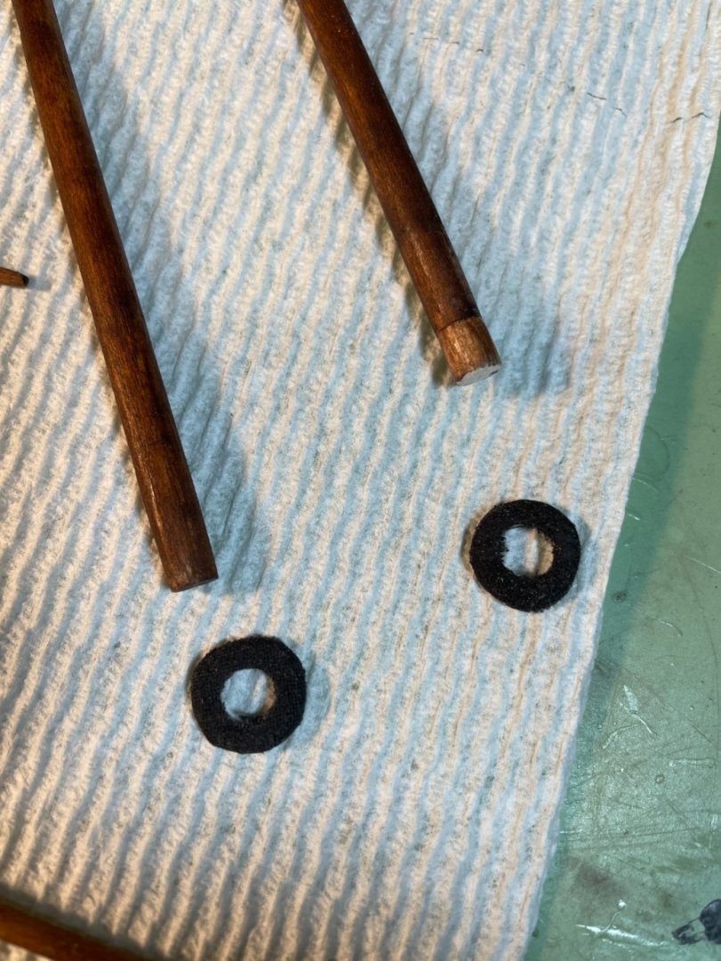
I also made up two mast coats for the masts by cutting out little wooden donuts and then covering them with cloth from an old handkerchief, painted black to simulate tar.
Blocks were added to the main mast.
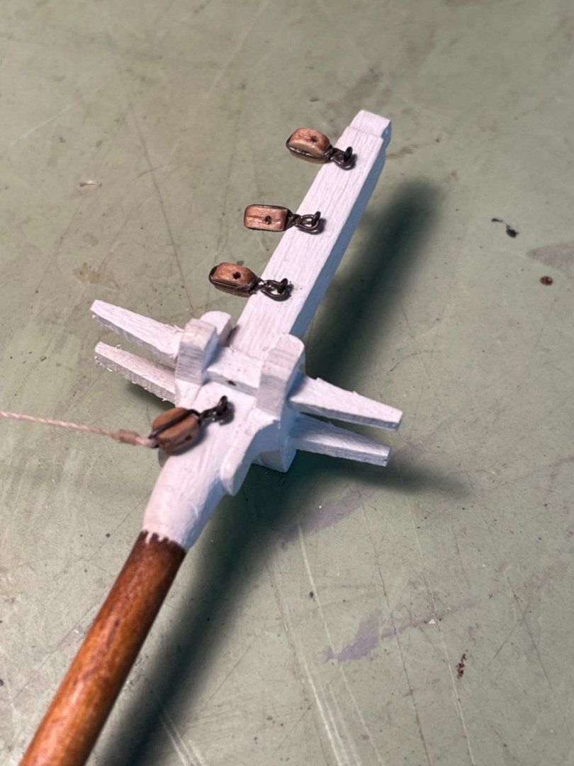
The traveler with its block was also added.

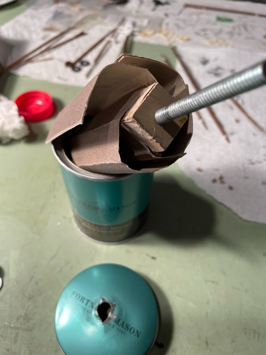
The instructions mention that the looks of the blocks can be improved by filing the corners off making them more oval shaped. Sounds kind of hard for big fingers especially for those 3/32" blocks so I thought I would share how I do it. I have a small can that is lined with 180 grit sand paper.

Into the can goes a wooden spool that I have attached four pieces of 220 grit sandpaper and a threaded rod.
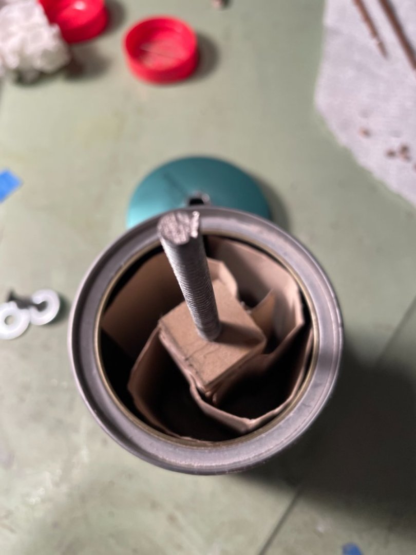
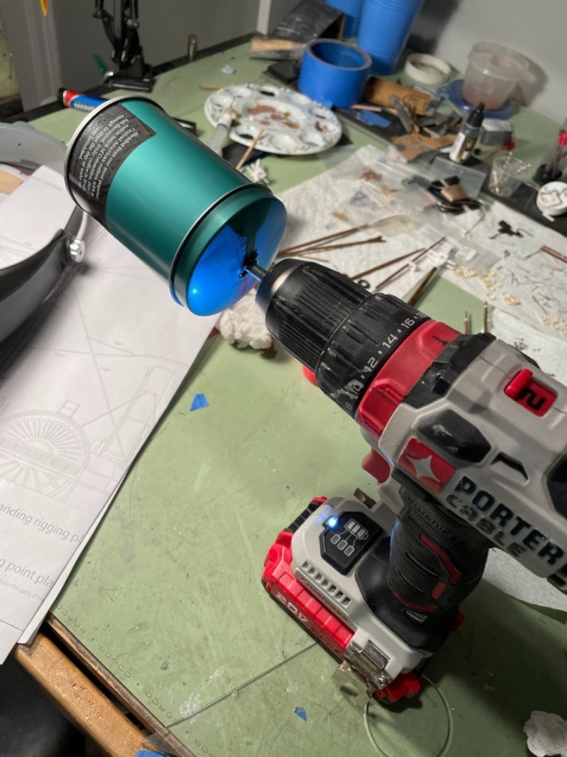
The blocks are placed inside the can, the top is put on and I spin it with an electric drill. You need to play around with it to know how long to go for but don't spin them too long or you'll end up with a pile of sawdust.
-
-
The two masts were temporarily assembled as per the instructions in order to position the fore and main chains and deadeyes.
Trestle and cross trees
Fore chains and deadeyes:
The one deviation from the instructions was the spacing of the fore deadeyes. Instead of the 5/16" spacing called for I used 9/32". The 5/16" brought the last deadeye too far into the sponsons on my ship.

Main chains and deadeyes:
The mast hoops were also assembled but instead of using the card stock that came with the kit I used a manilla folder. The folder was stained to darken it a bit with varnish (hard to see in the photo). I used the manilla folded so I wouldn't need to paint the loops.
To form the loops I used a 5/16" drill bit for the lower loops and a 3/16" bit for the upper.

-
First, I would like to thank everyone for all the likes, comments and for following along.
Finishing a few odds and ends before starting on the masts. Chain trusses for the sponson support were added.
Aft chains:

Fore chains:
Funnel support guy wires were added. I had some gray thread left over from a model plane I had made that worked out fine.
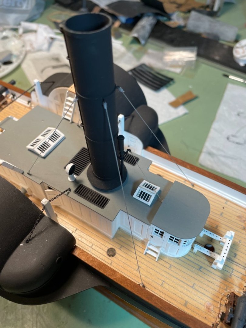
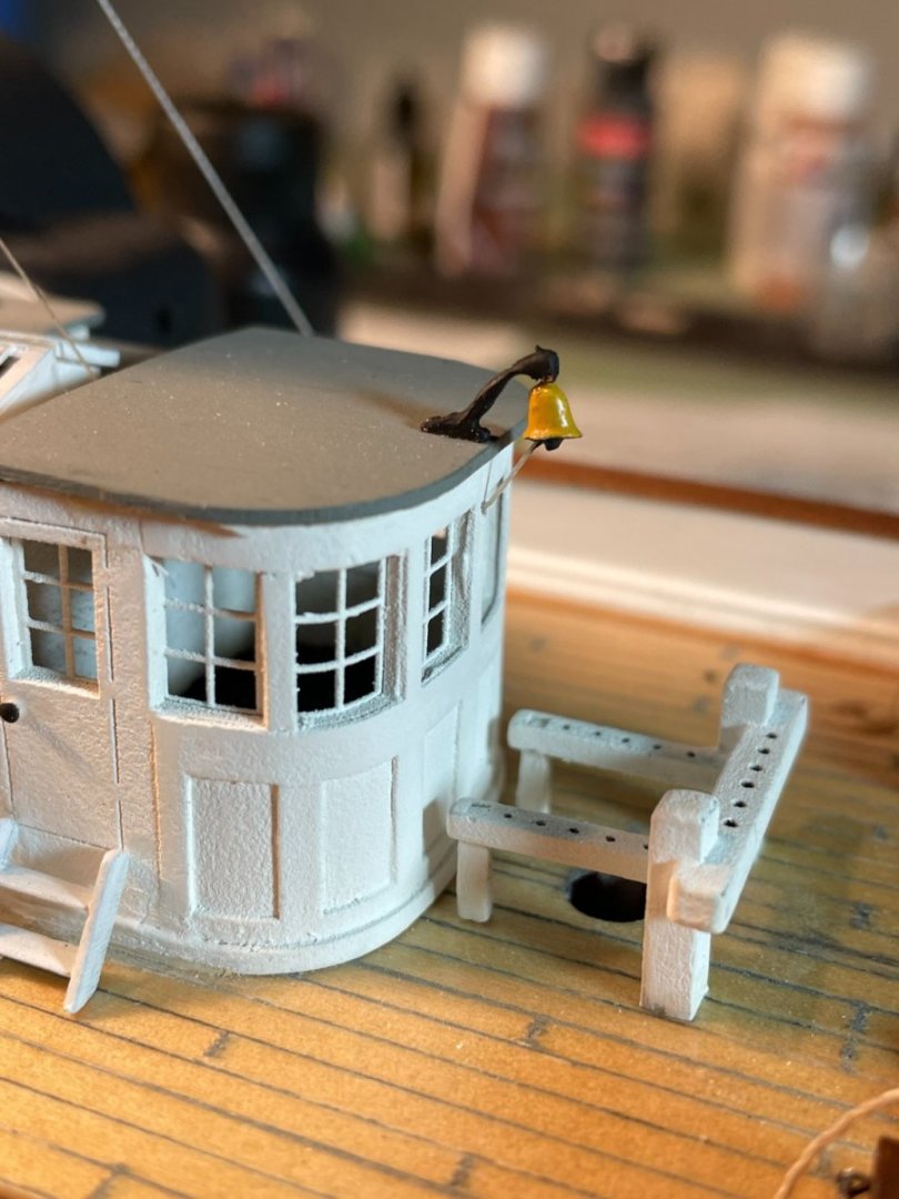
and the ship's bell. Added a pull cord into the cabin.
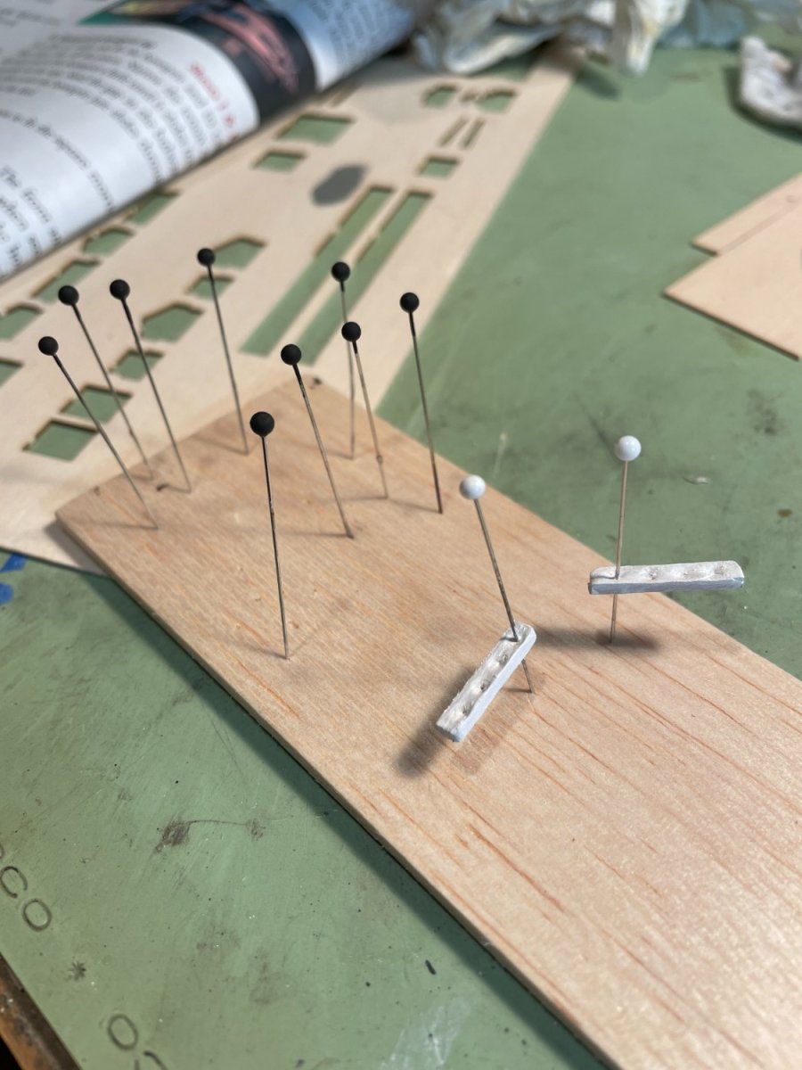
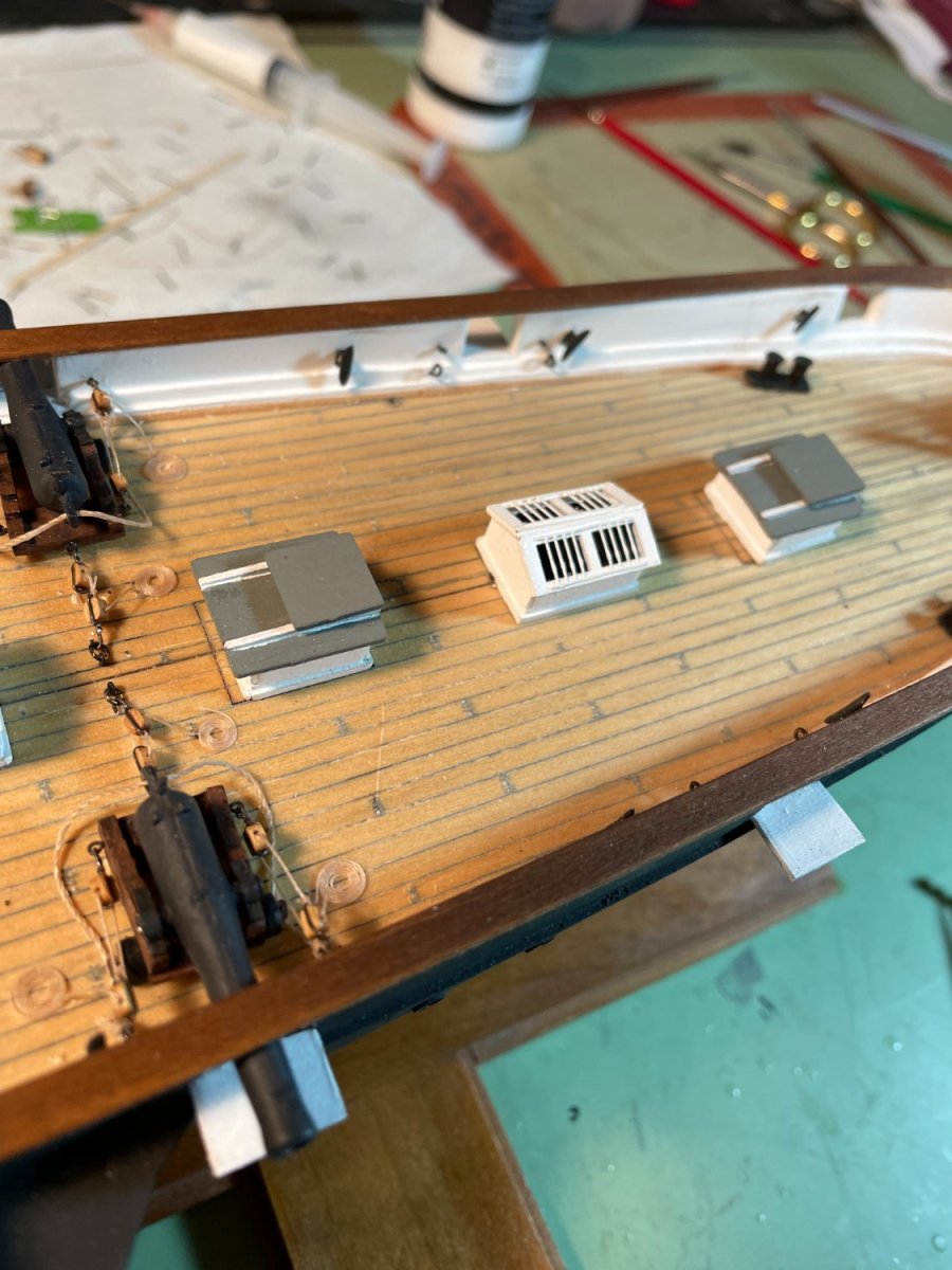
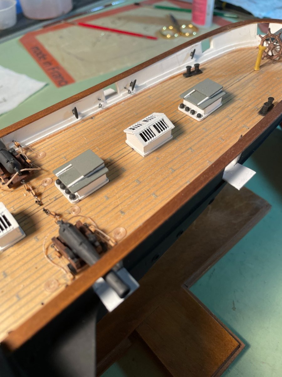
Then there were a couple additions that I chose to add. First, to coverup the laser etch guide lines in the deck planking adjacent to the aft companion ways I decided to make a couple of brass monkeys for cannon ball storage. Cannon balls were made using the ends of straight pins painted black.

Before:

After

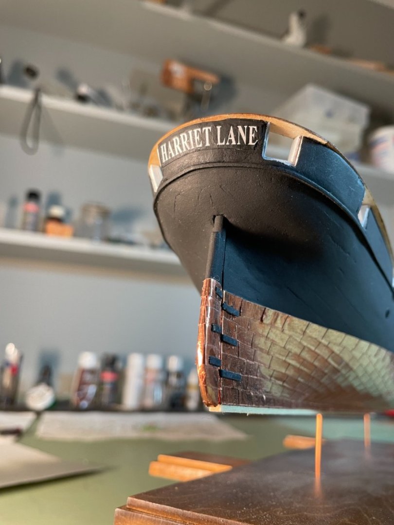
Last but not least I added her name to the stern.
- bobandlucy, rlwhitt, Jack12477 and 2 others
-
5
-
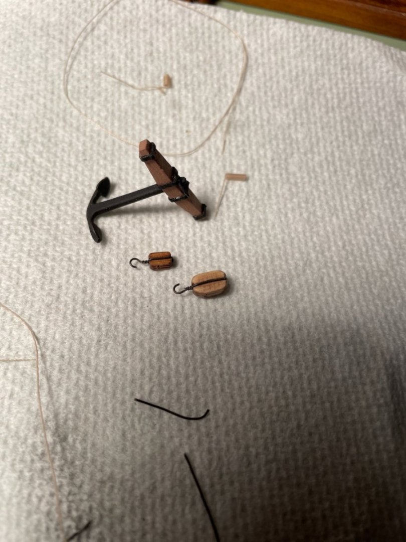
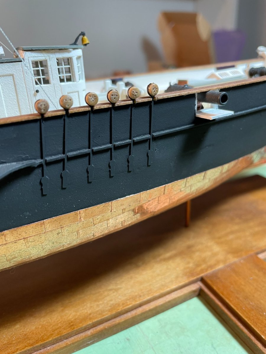
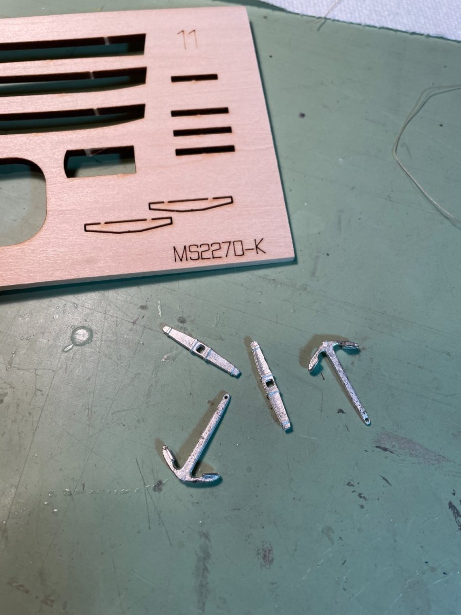
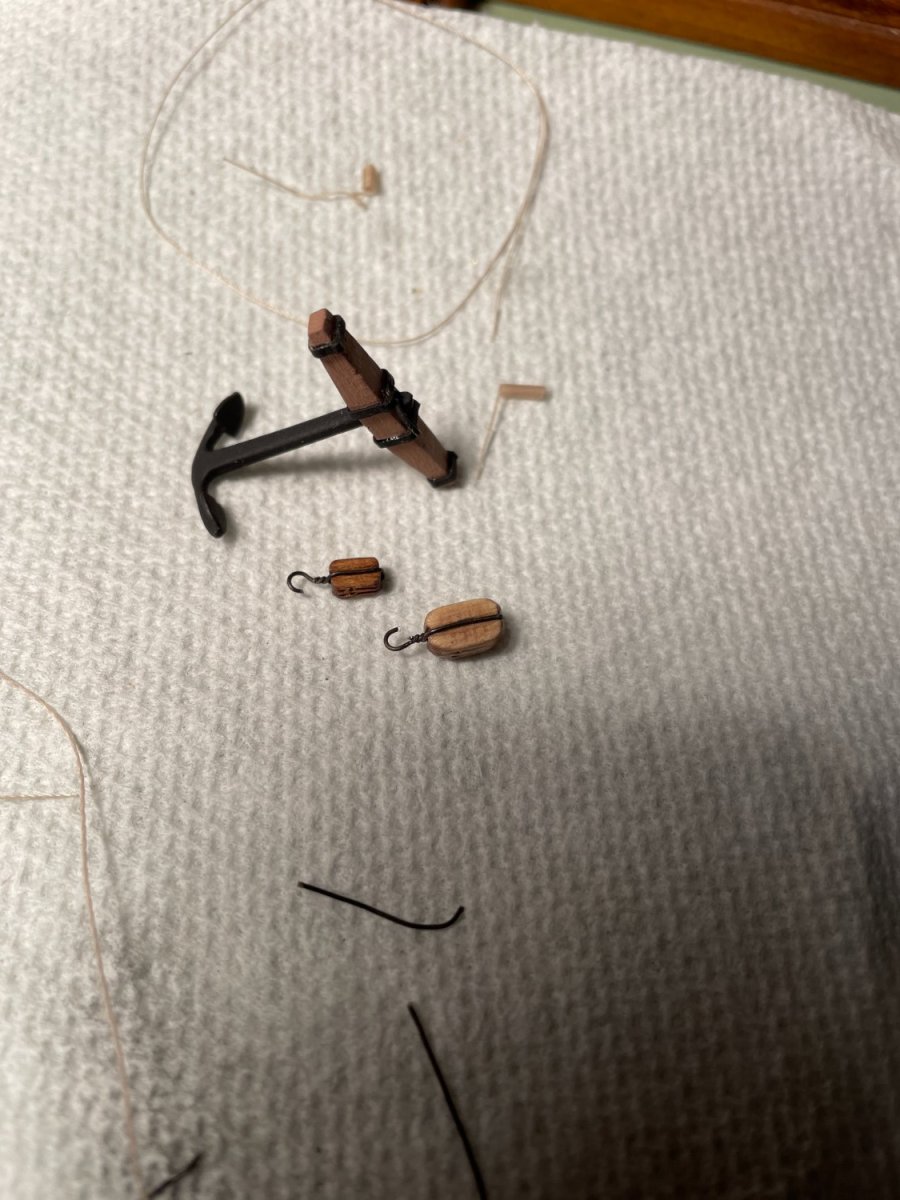
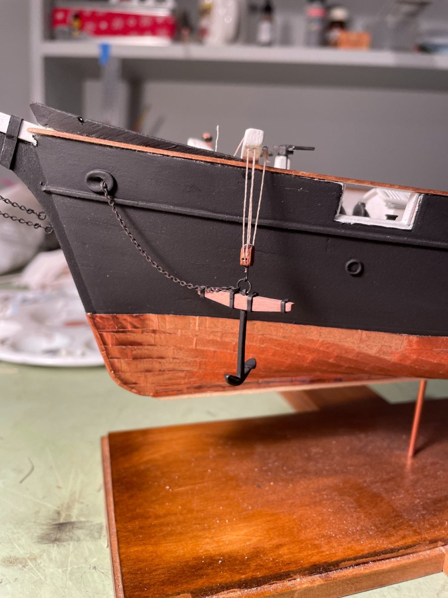
Anchors and stocks:
My kit came with two options for the anchor stocks, one wood the other britiannia metal. I chose to use the wooden stocks.
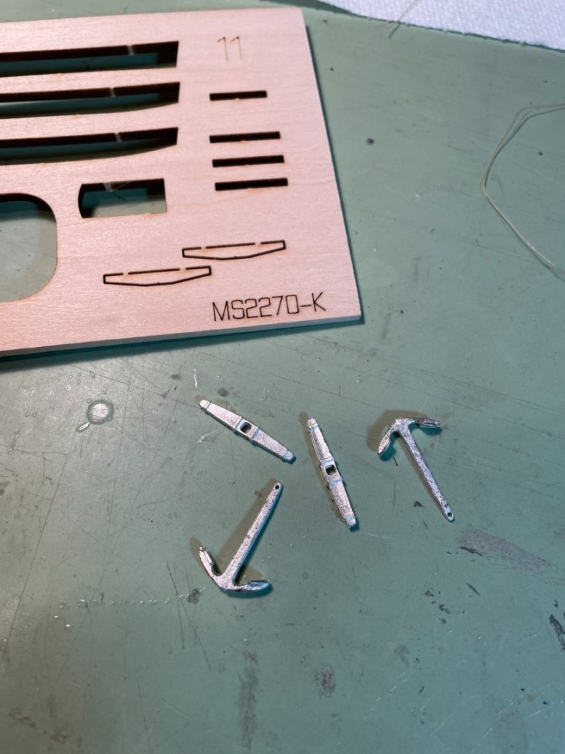
I used some of the card stock painted black and glued to the wood stock to represent metal strapping. I also decided to use a smaller size block for the cathead block and tackle than the 7 mm block provided.
I went a little rogue with the placement of the anchors and didn't follow the instructions too closely. On one side I decided to show the anchor in its raised position lashed to the cap rail.
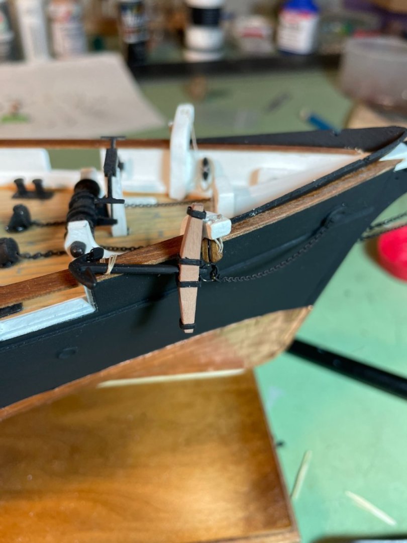
For this option I needed to add an additional cleat to the inside bulwark in order to secure the lashing to.
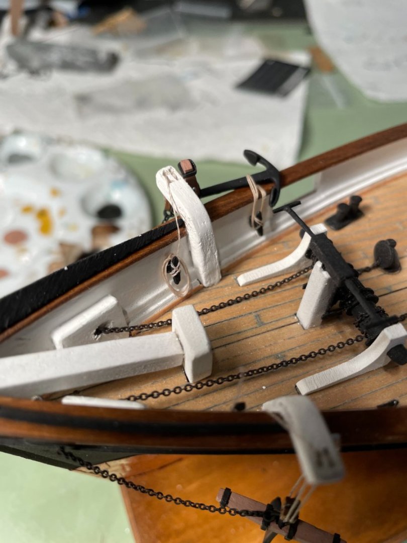
On the other side I decided to show the anchor still being raised.

- Canute, bobandlucy, clearway and 3 others
-
6
-
-
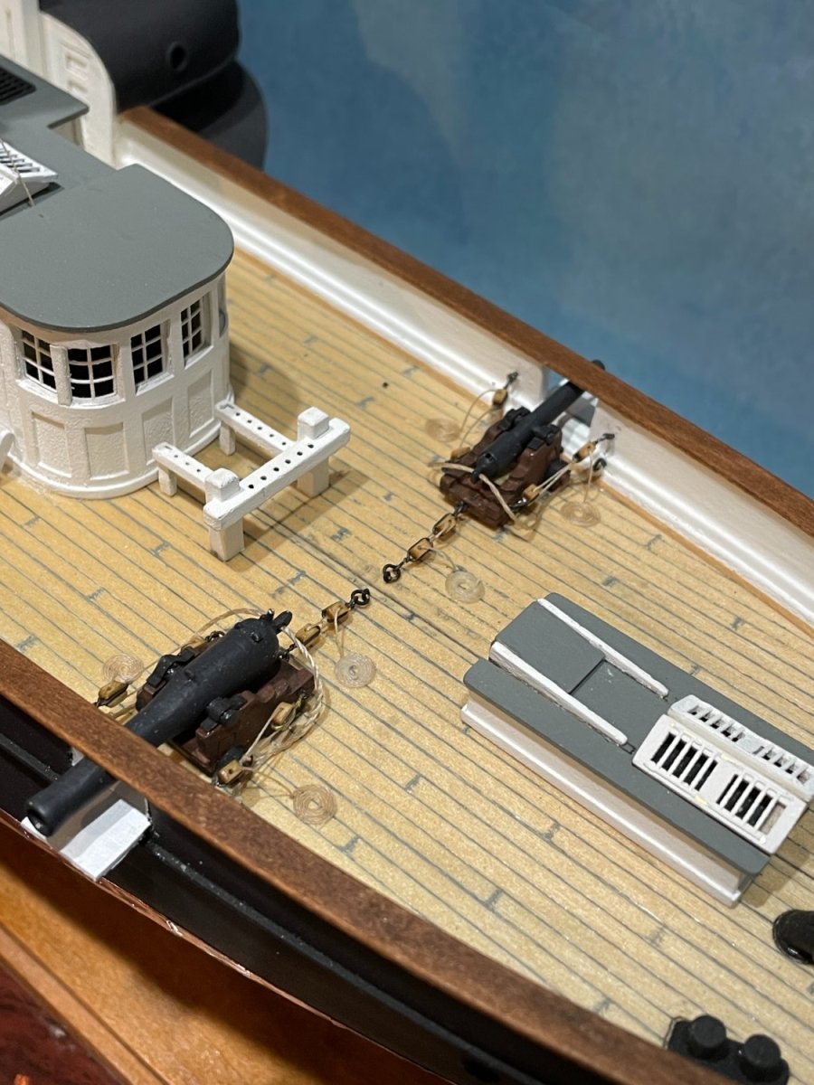
She has her teeth!
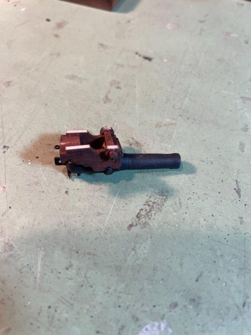
After installing the gun ports lids the cannons were added. I had the same problem as rcmdrvr had in his build that the cannons were too high for the port openings. I used a suggestion made by Snug Harbor Johnny in rcmdrvr's build to file down the carriage bottoms and the carriage wheels in order to gain some room. This worked out well and you can hardly notice the flattened wheels with the guns on deck.
I had some 2mm blocks left over from another build so I decided that I would add the out haul rigging.
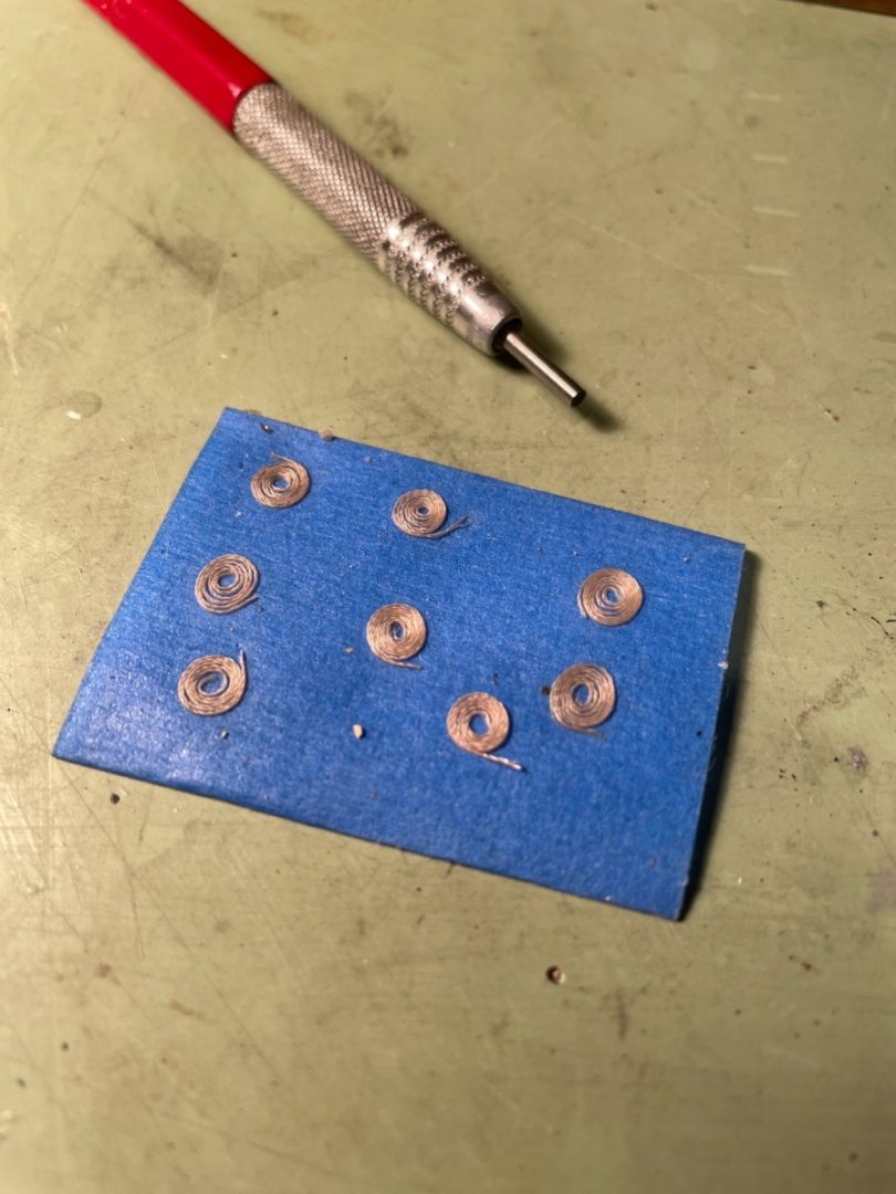
Rope coils were made to be added later.
I also decided on this build that I would show the in haul rigging as well.
Aft cannons
Forward cannons
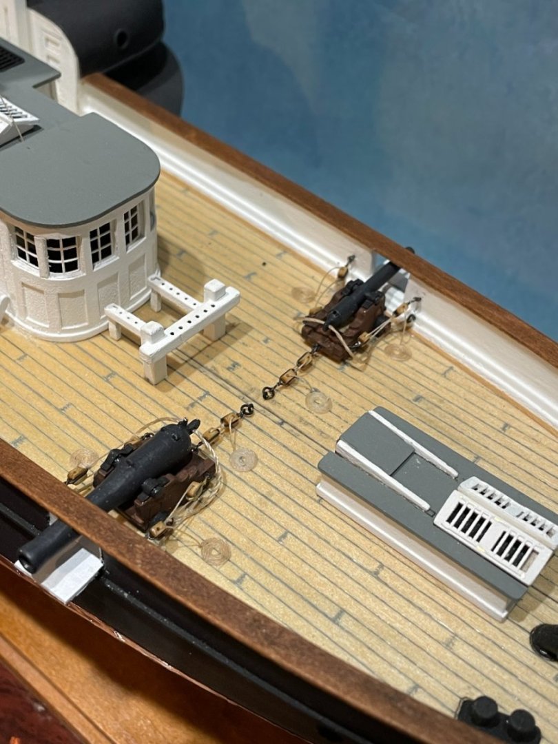
All her teeth
-
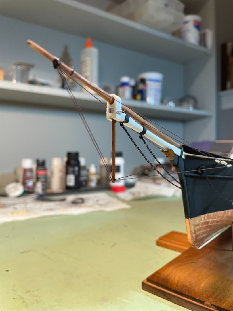
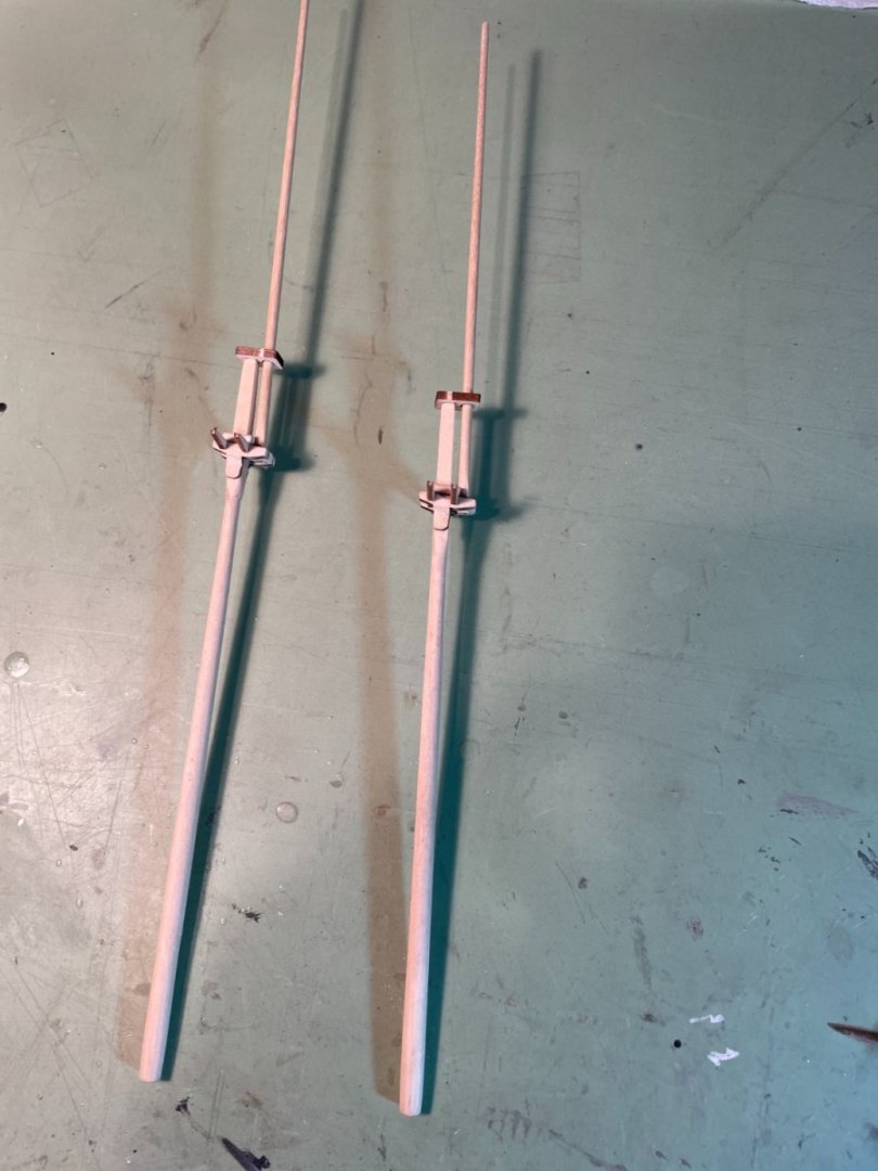
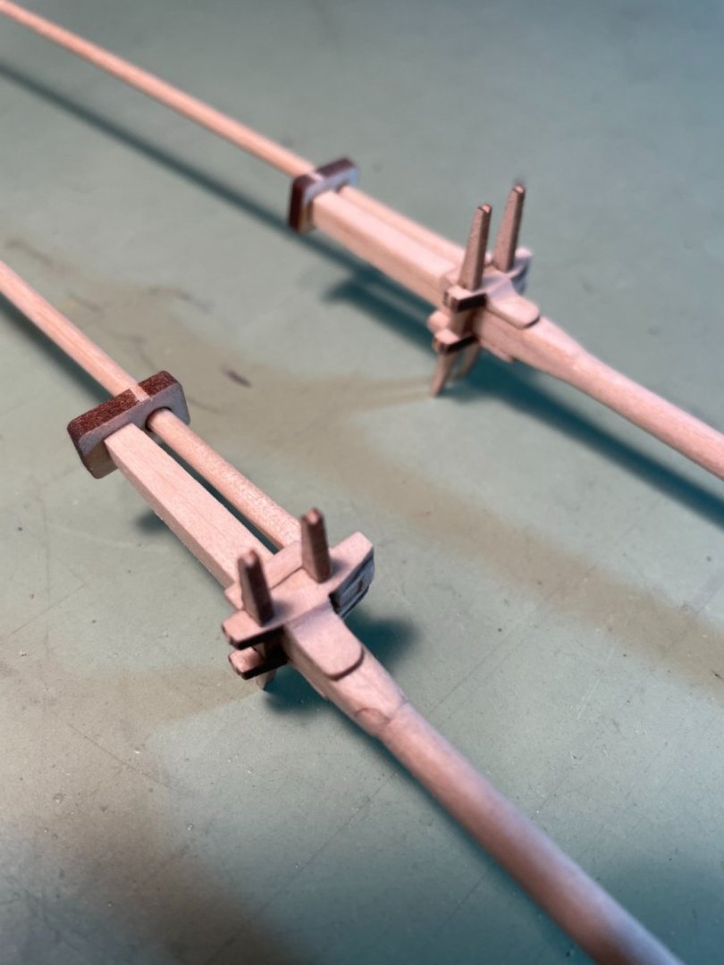
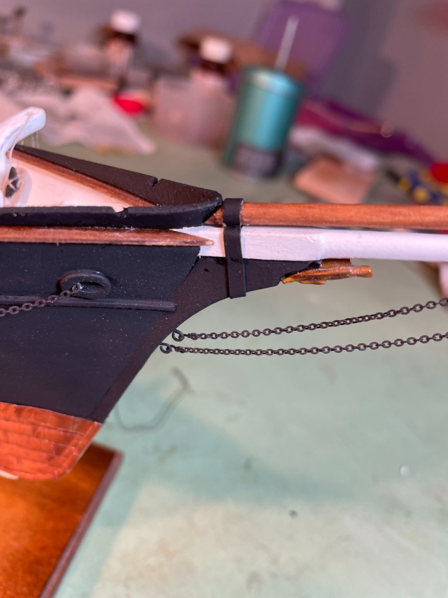
Bowsprit & bowsprit cap:
I shaped and fitted the bowsprit as called for in the instructions along with the bowsprit cap. The card bands and gammoning strap were added. I chose to paint the bands black instead of white as shown in the instructions. I like the contrast and how they show up better.

Bobstays:
The two bobstay chains were added.
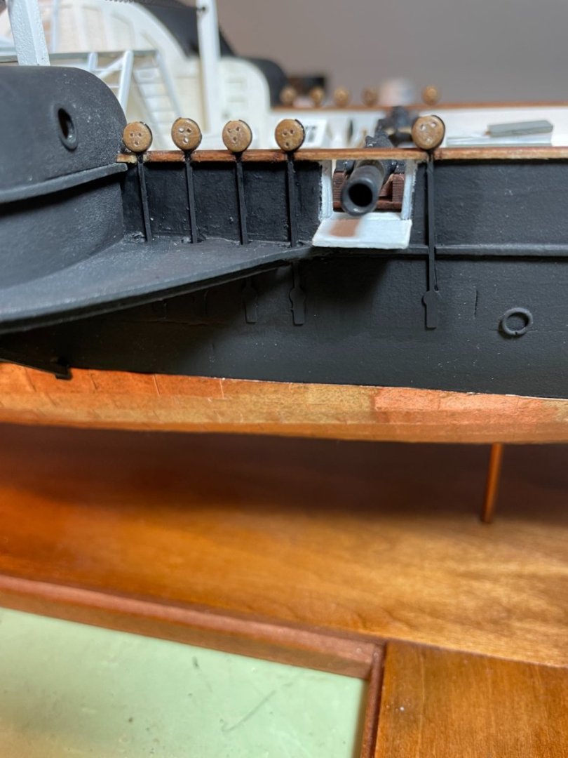
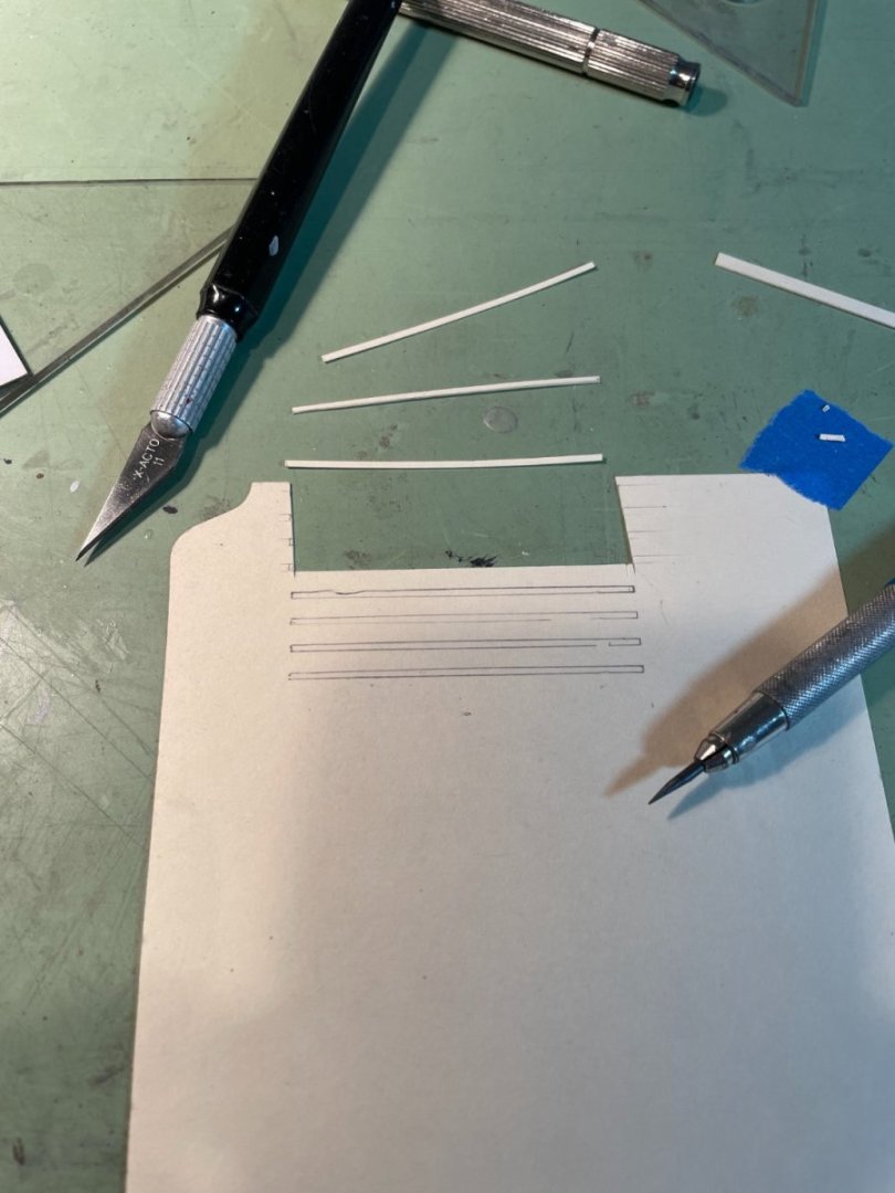
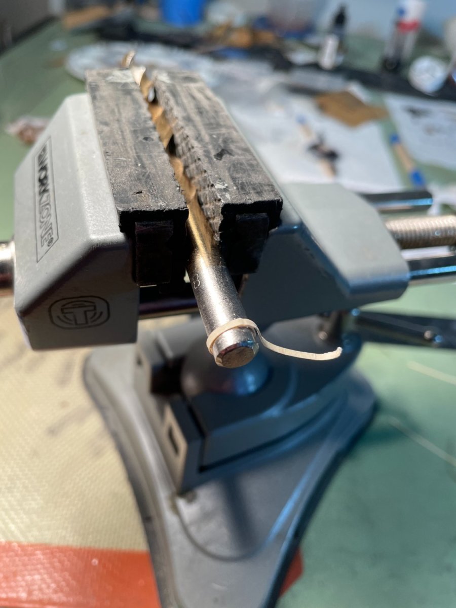
Bow fairlead:
Things were going along well until I got to this step. As you can see in the picture below my two attempts at bending this piece ended up in failure. The two pieces were both soaked AND steamed but they still broke as I tried to bend them around the 1/8" dowel. I do believe however that the way the pieces are positioned on the wood sheet makes them almost impossible the bend without breaking. The piece is layout so you are bending it along the grain instead of across the grain (if that make sense). I made my own piece so the bend was across the grain and I had no problem bending it.
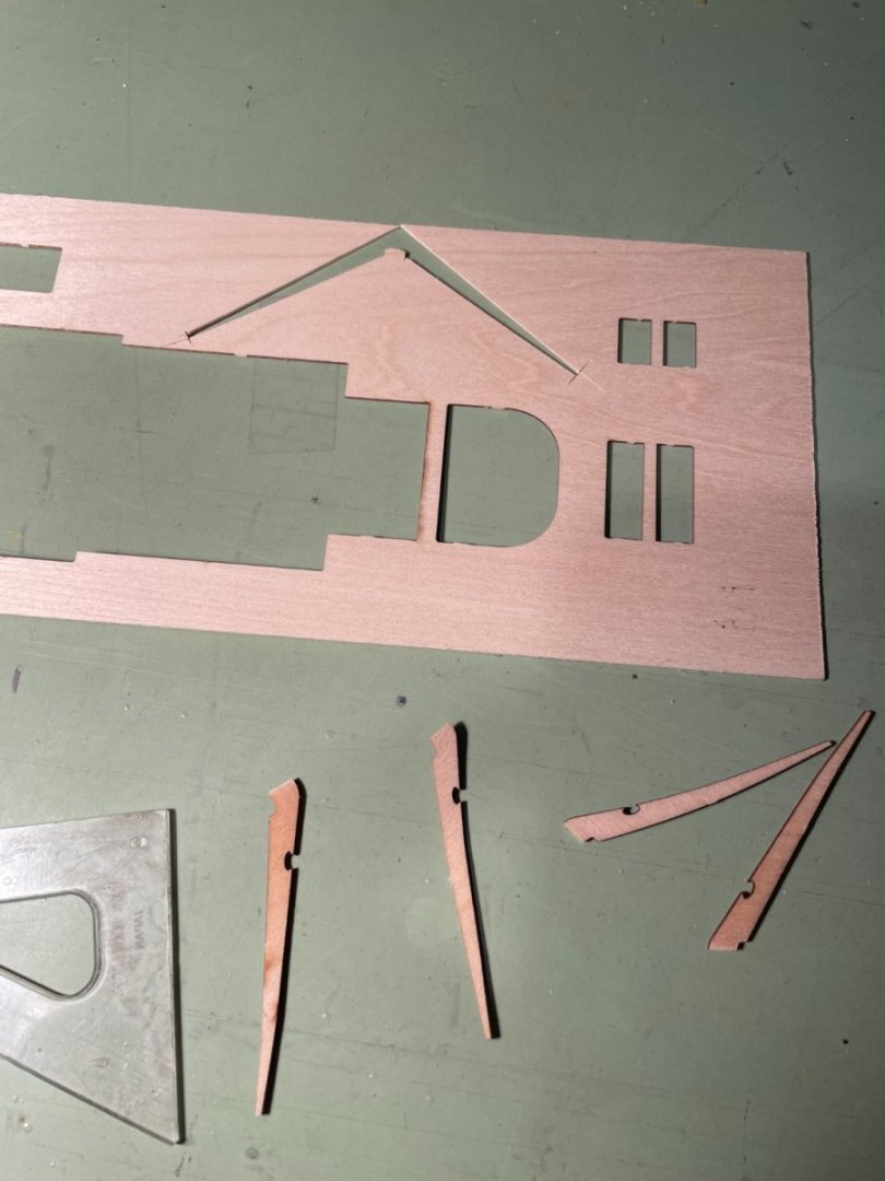
Fairlead painted and installed.
- Jack12477, Mirabell61, bobandlucy and 3 others
-
6
-
-
-
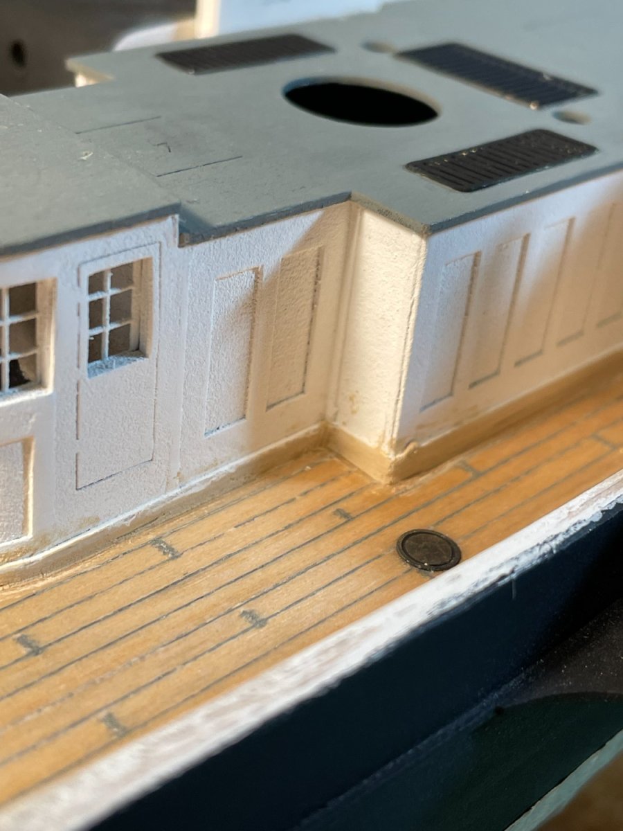
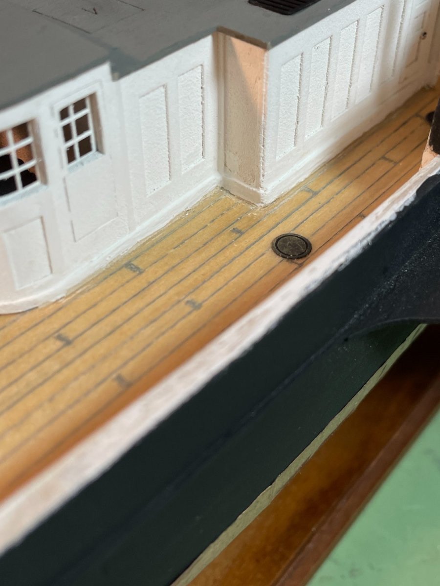
Small update. The aft companion ways and skylights were assembled and installed along with the rudderhead housing and compass pedestal. The companion ways are a little smaller than the laser etched guidelines in the deck used to position them so the lines do show a bit at the ends. For future reference to myself, I like the simulated decking but I wish I hadn't showed the butt ends of the planking. It came out too dark.
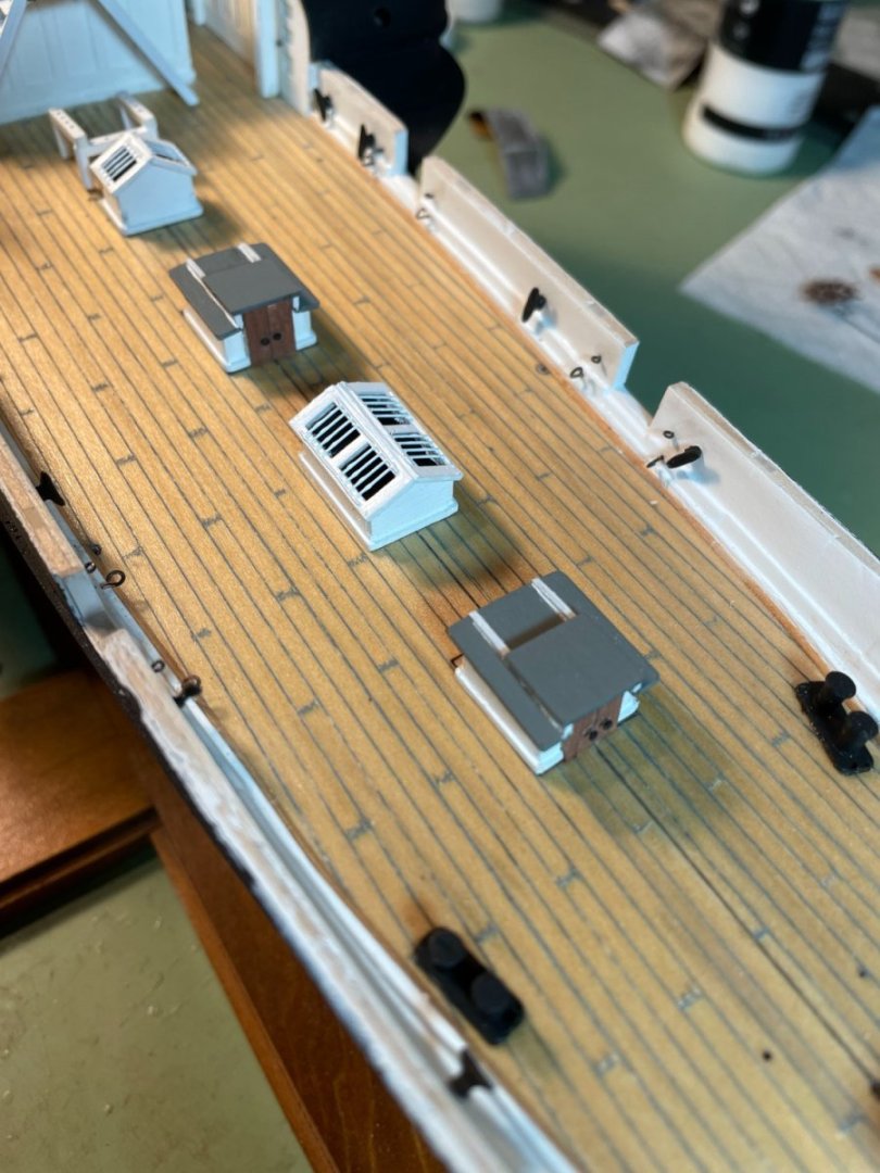
The bulwark rails were fitted and glued in place. I chose to stain the railing.
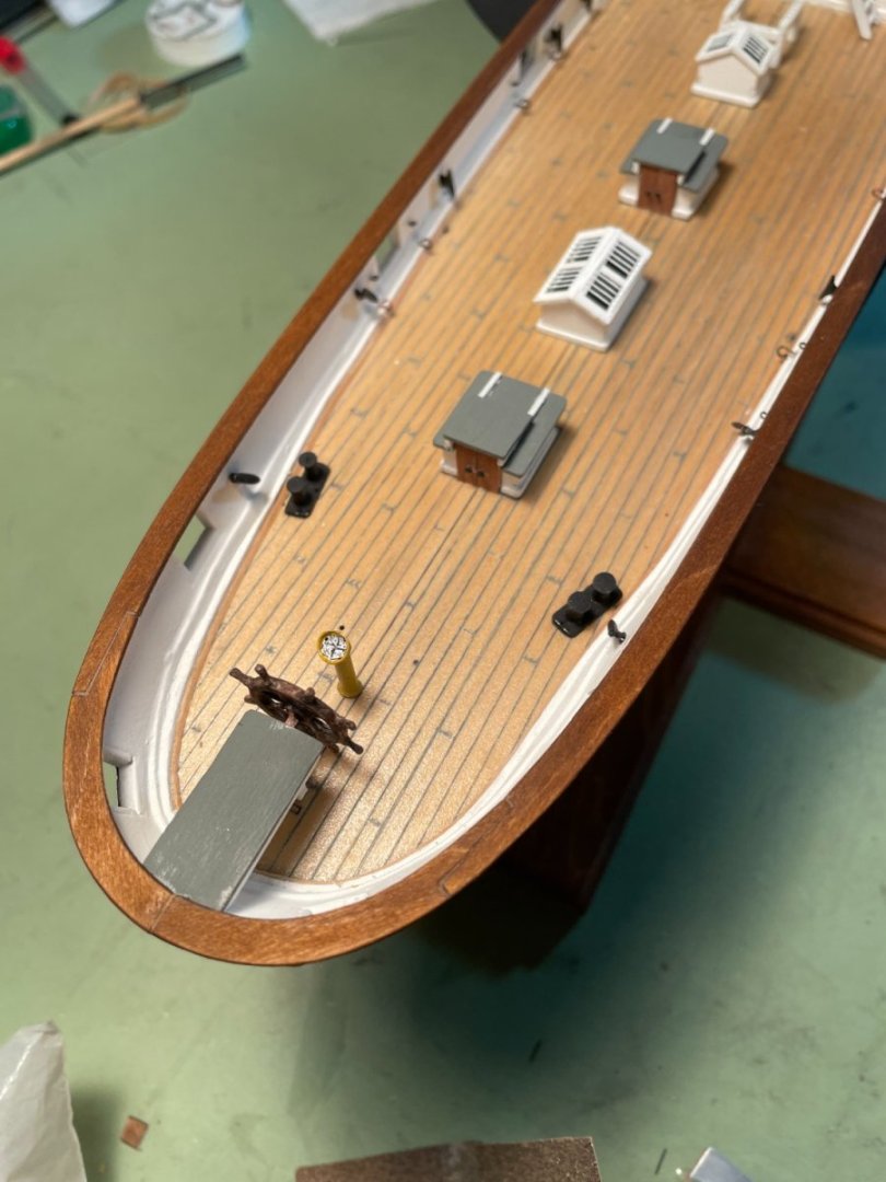
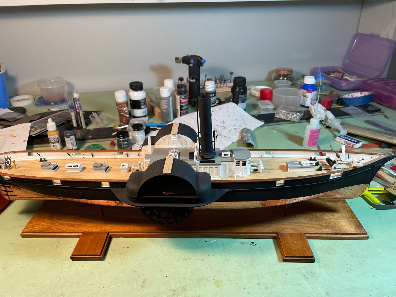
Ship as of today. I need a better background

I also would like to thank everyone for all the likes.
- Mirabell61, Canute, Pete Jaquith and 8 others
-
11
-
My next task was to install the eyebolts for the gun tackle into the bulwarks. I wanted to make sure that I positioned them correctly so I decided to assemble the gun carriages first. After assembling the carriages I decided that I might as well complete the assembly by adding the cannons. I was a little dishearten by the size of the cannons, as I think most of the people working on this kit are, because they just look to big for the ship. I did a little research, and I do mean little, and I found that the overall length of the 9" Dahlgren gun is 131" (10'-11") and the 4" Naval Parrott rifle is 102" (8'-6"). Tables below.
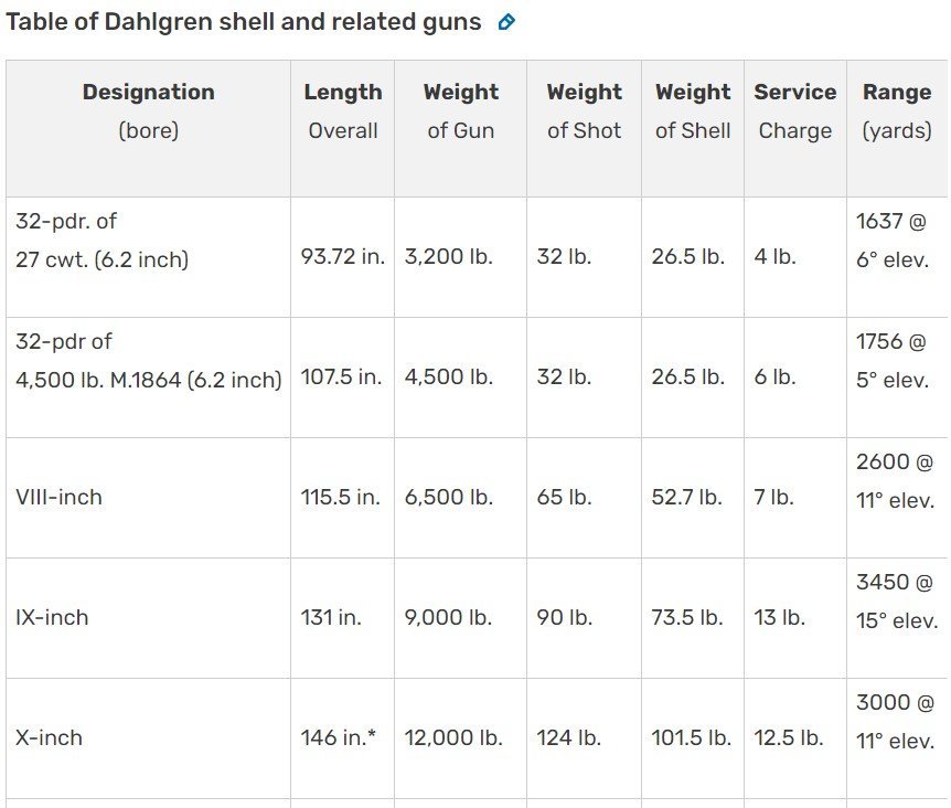
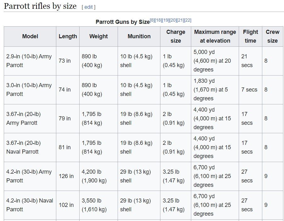
Using my trusty engineer's scale (please excuse it's rough shape) I scaled the cannons and found that at 1/8" to the foot, they are in fact very close to the actual dimensions. This made me feel better using these cannons and not having to purchase new ones.
Dahlgren gun

Parrott rifle
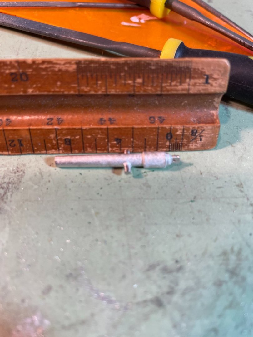
Cannons cleaned up, and the cannons I received the barrels were not bored out so I drilled the ends of each one.
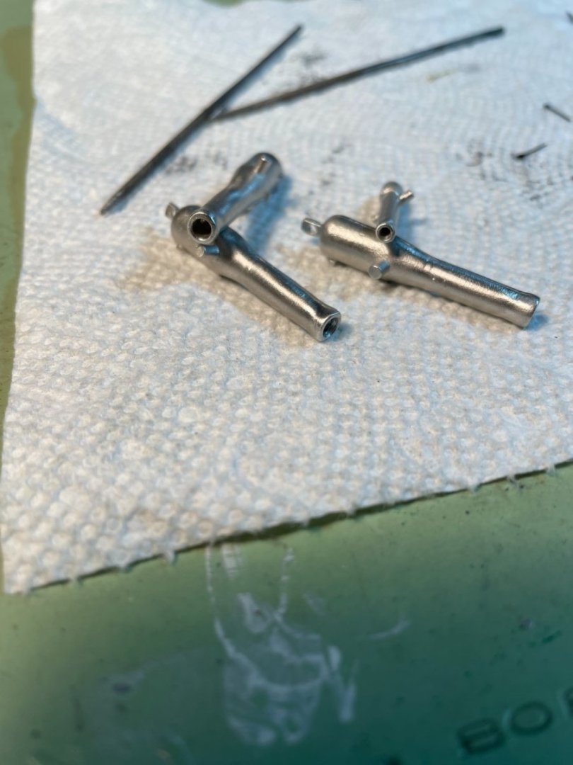
Completed gun carriages. It's hard to see but I did add the elevating screw at the rear of each Dahlgren gun.

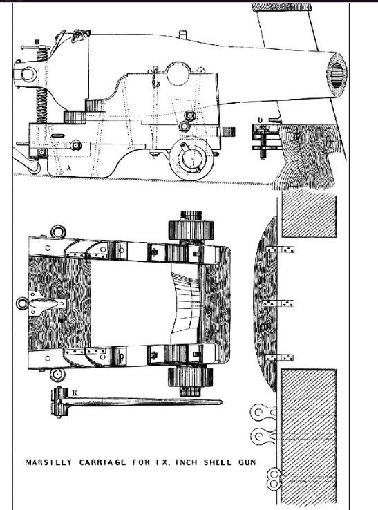
I also found a nice picture of the Marsilly carriage that I used for reference.
-
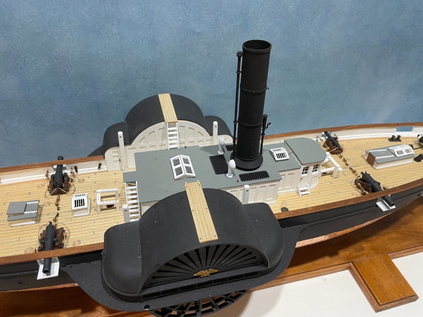
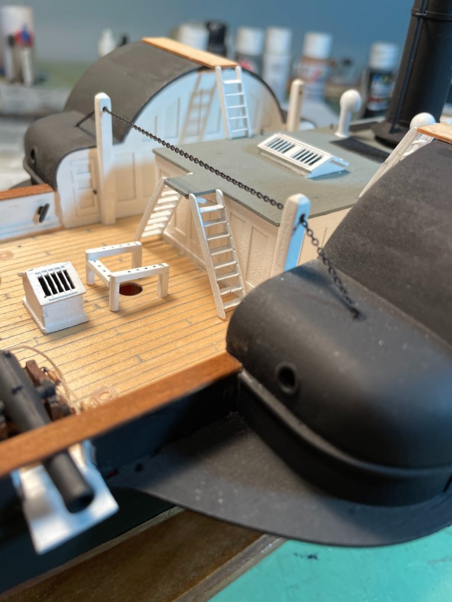
The bridges and the main mast bitts were the next task. After reading bobandlucy's build and seeing how Bob had a problem with the two access ladders for the bridges being too short I decided to move the two platforms inboard a little so the ladders would reach. I chose not to paint the platforms but left them natural. I also scored them to simulate planks.

The main mass bitts were assembled, painted and glued in place.

-
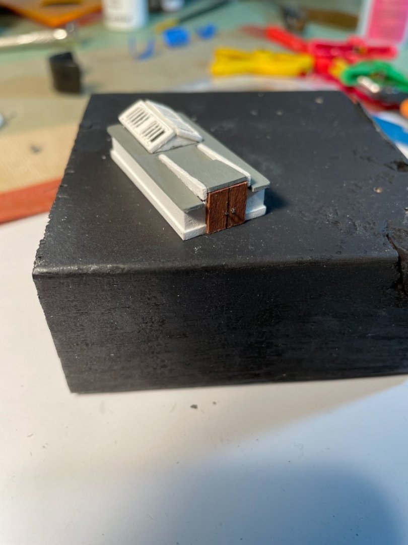
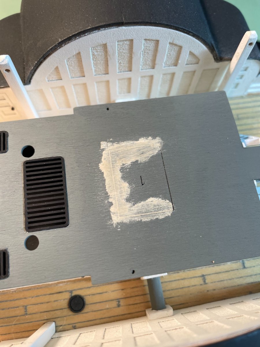
Cabin Skylights:
After assembling the aft cabin skylight I noticed that the laser etched positioning guidelines on the roof were way to big for the skylight. I chose to fill in three of the four guidelines with wood filler and then repaint the roof.

Repainted roof

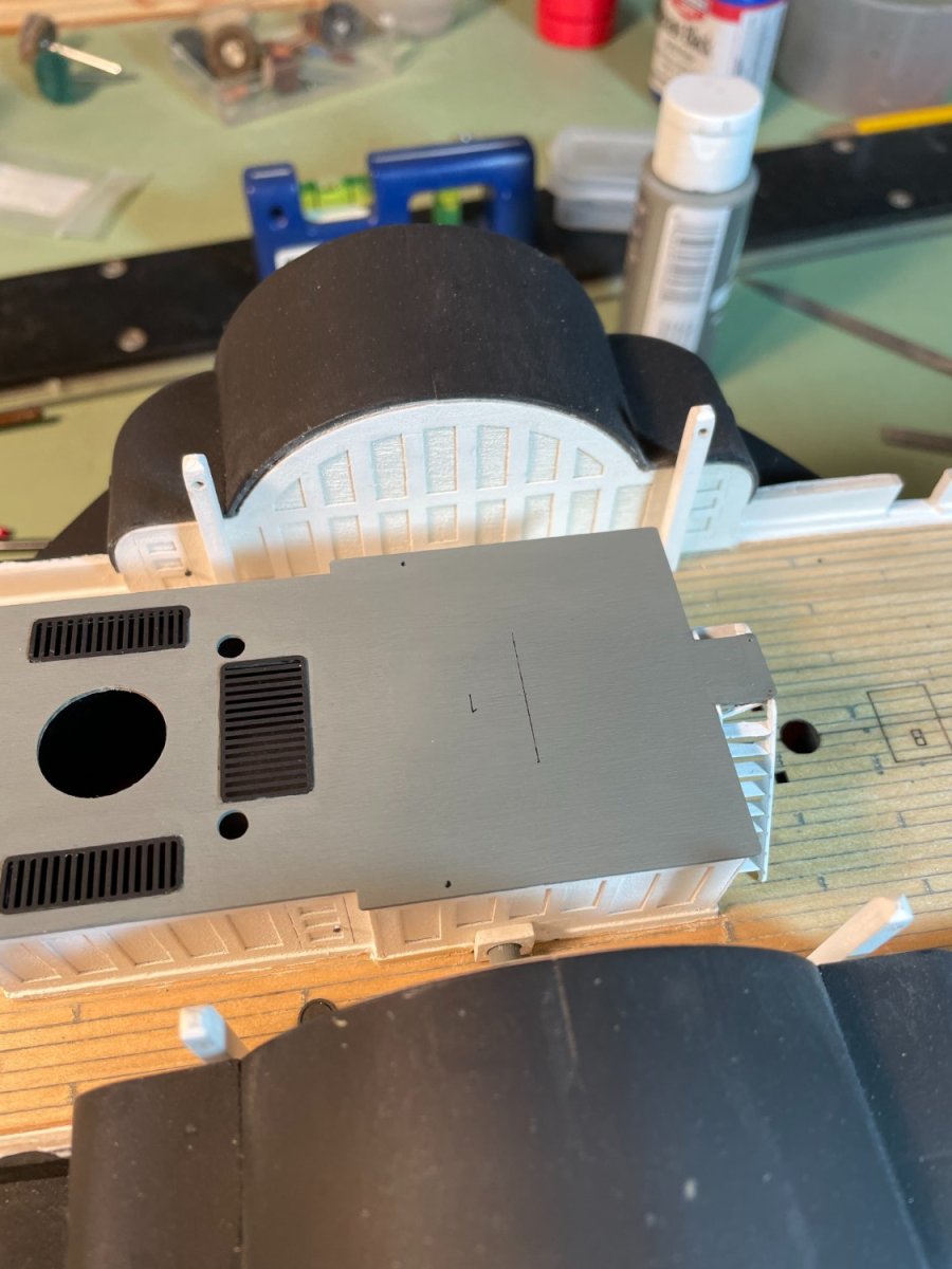
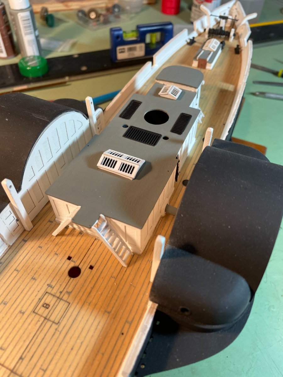
Skylights glued to roof

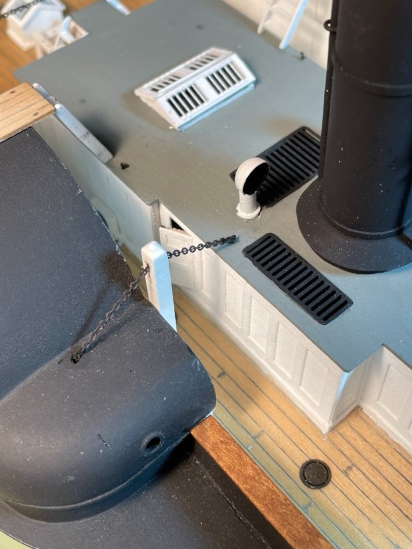
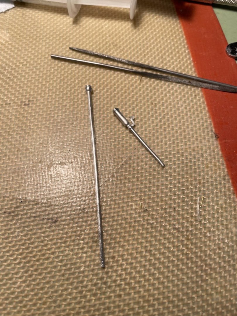
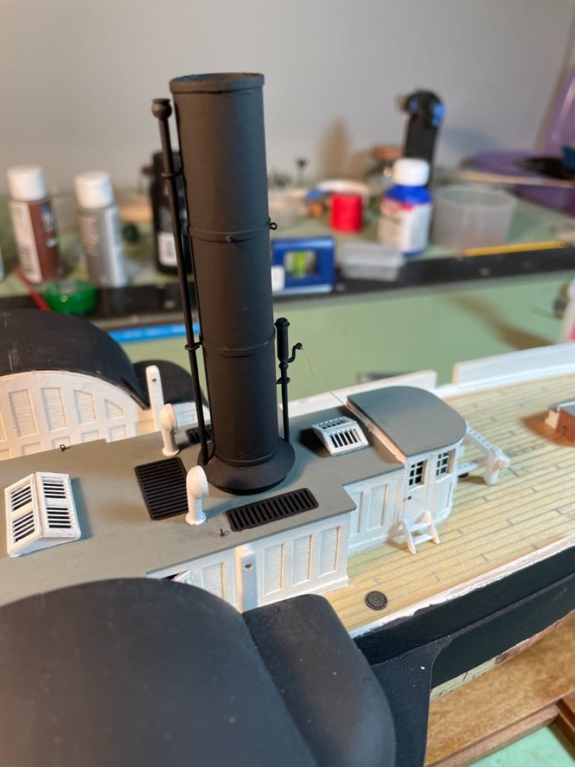
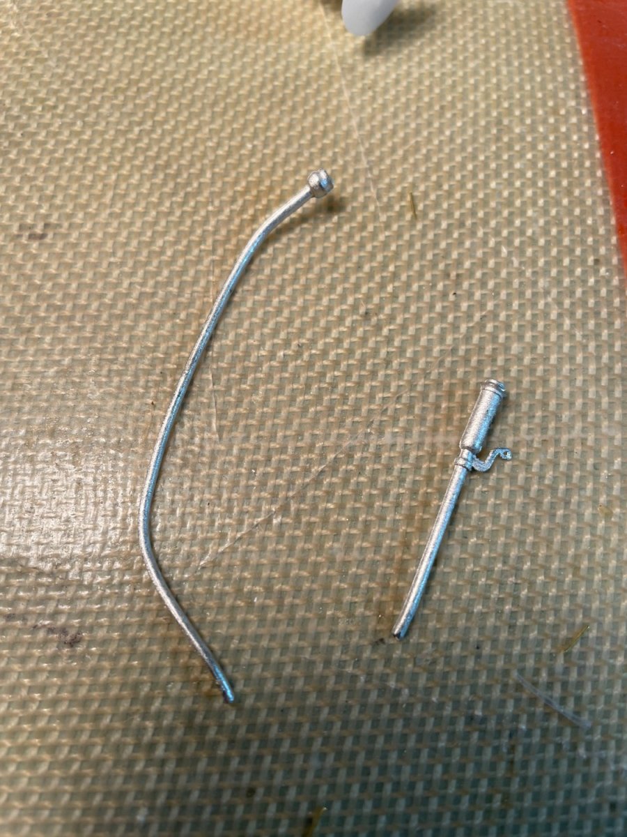
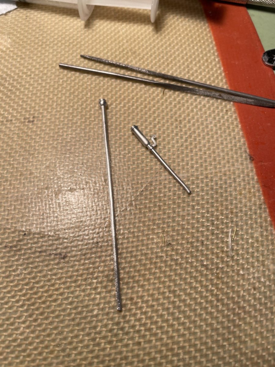
Funnel assembly:
The funnel assembly was next and the first thing I did was to clean up the britiannia steam pipe and whistle.

After cleaning and straightening.
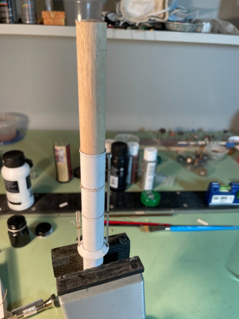
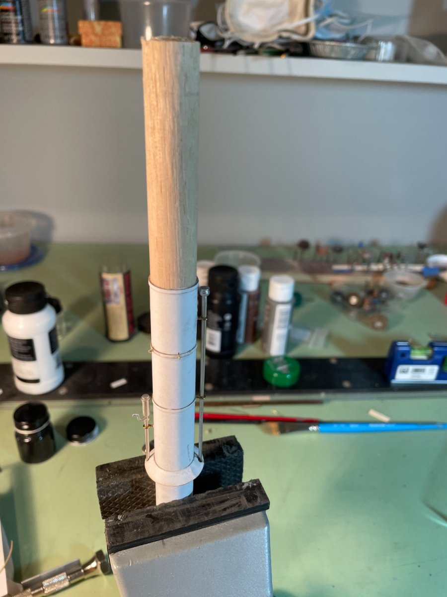
The funnel was assembled per the instructions using the card stock wrapped around a wooden dowel. I used a scrap piece of dowel inserted in the upper part of the funnel to keep me from crushing the card stock while handling it.
Painted funnel
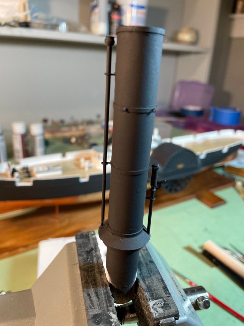
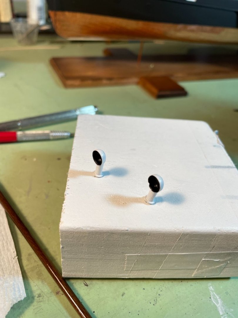
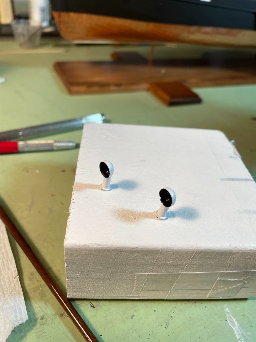
The two ventilators were cleaned up and painted
Completed funnel assembly
- rcmdrvr, Canute, GrandpaPhil and 3 others
-
6
-
-
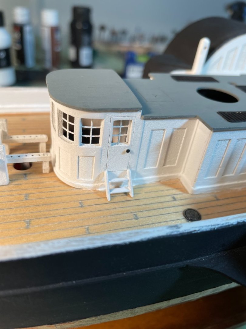
Mounting the cabin & pilothouse:
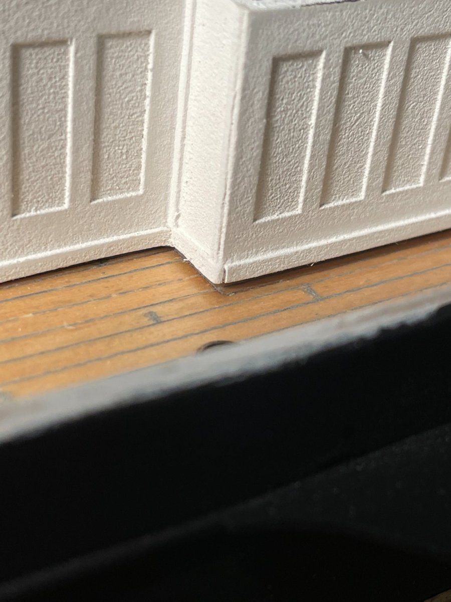
I ran into a little problem when setting the cabin on the deck. I think I must have a slight dip in the deck because there's a gap between it and the cabin floor. I had already installed the base molding so I couldn't adjust that.

In the end I used a bit of wood filler to fill the gap.

Looks a little rough in the closeup but at viewing distance it's not too bad.

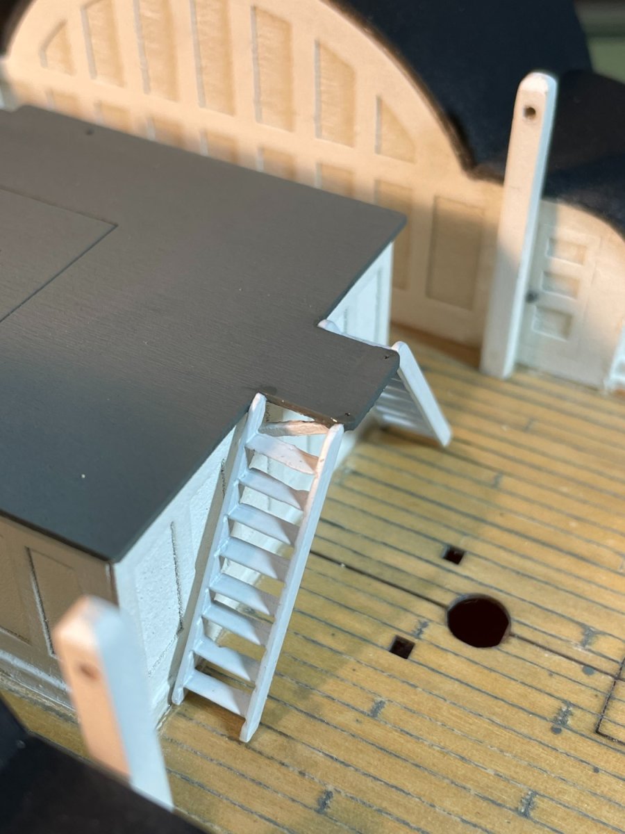
My next issue was the ladders located at the rear of the cabin. The platform extension was not long enough. Bobandlucy's build mentioned this problem but I read about it after the fact.
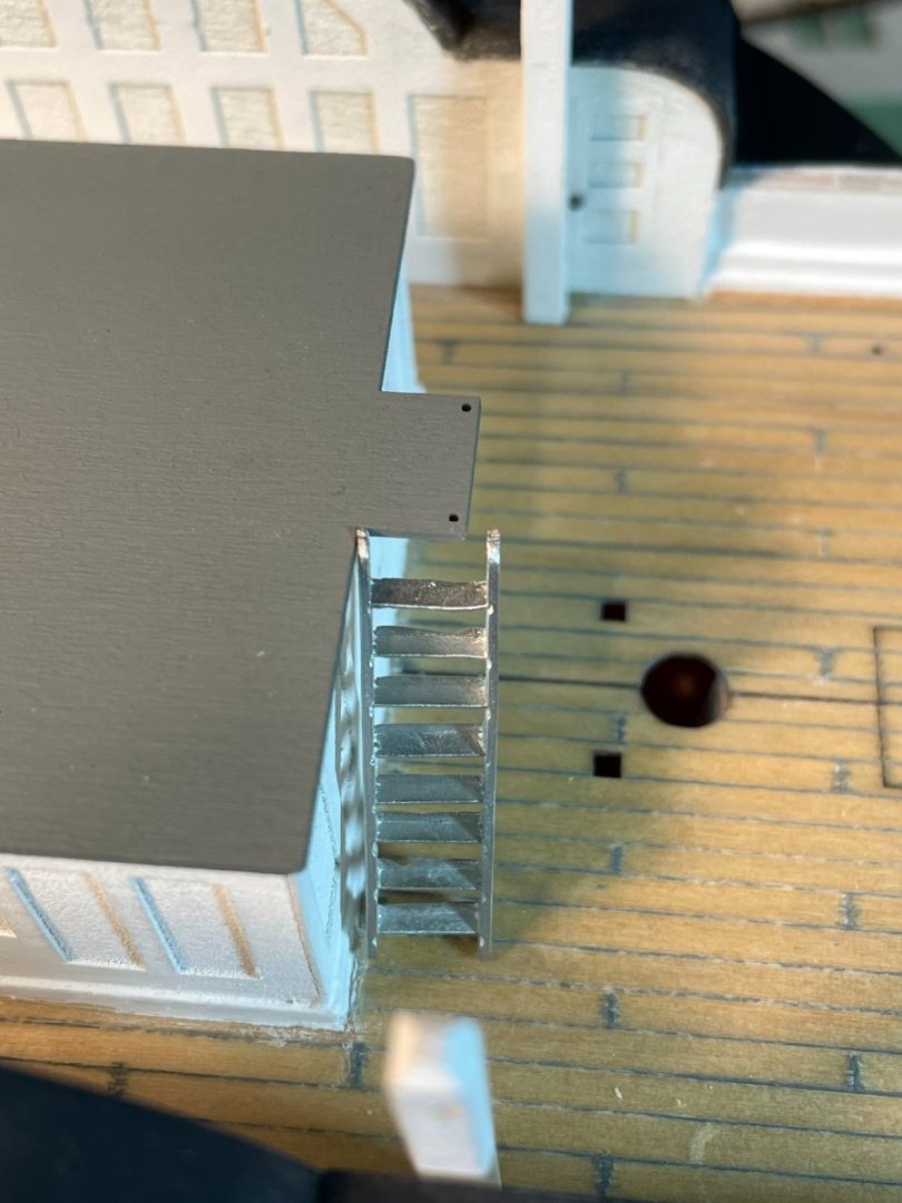
I decided to extend the platform in order to fit the ladders.
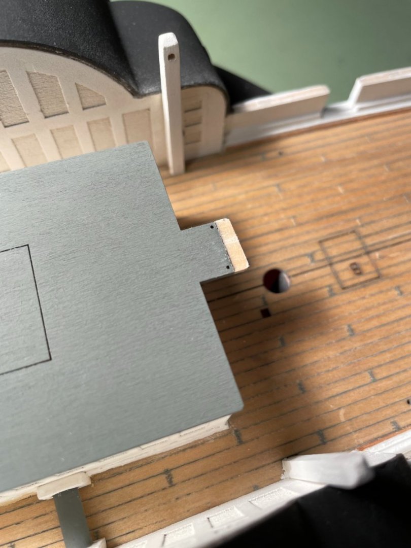
The handrail holes were redrilled and the platform was repainted. Being a retired structural engineer I had to add a couple knee braces for looks.
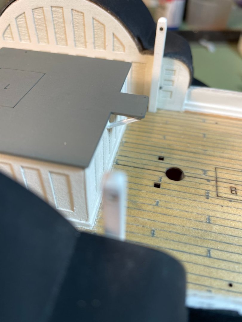
Ladders painted and installed

Forward ladders installed.
- GrandpaPhil, ccoyle, bobandlucy and 4 others
-
7
-
20 hours ago, druxey said:
Well adjusted, Sal!
Thanks druxey. I'm assuming you're talking about the boat because I'm far from well adjusted. 😁😉
15 hours ago, rcmdrvr said:Great job on your cabin and pilothouse.....I don't understand why your photo etch fit so well.
Thanks rcmdrvr. The fit may have had something to do with me building the walls first. I had to modify the base quite a bit to make it fit. The outer card layer didn't fit to well though.
Thanks to everyone also for all the likes.
-
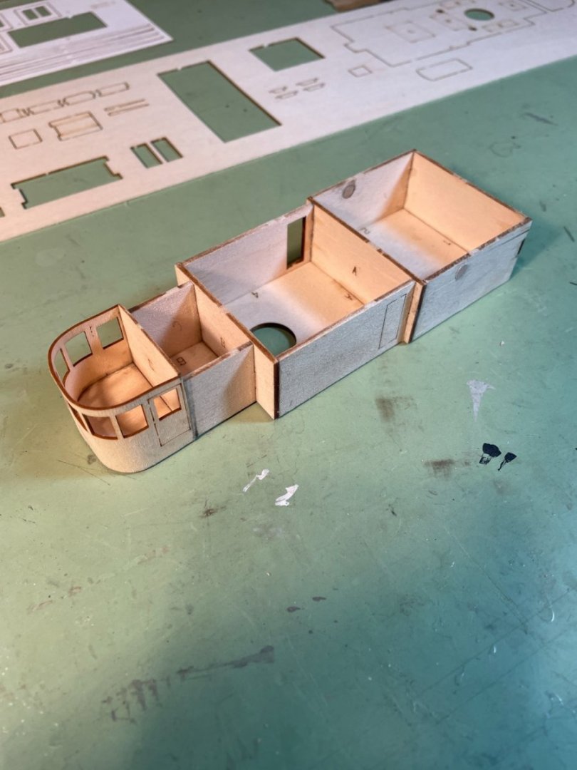
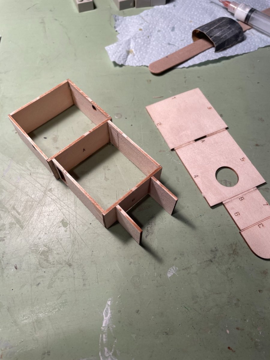
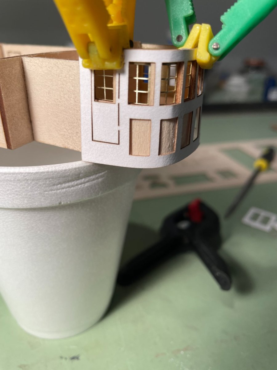
Cabin & pilothouse:
I started the cabin and pilothouse assembly following the instruction booklet but after gluing a few of the wall sections to the base I found that they just didn't fit the base correctly. The wall sections were too short. Good, bad, right or wrong, I chose to I disassembled what I had done and to then glue all the wall sections together first and then adjust the base to fit.

Completed cabin and pilothouse
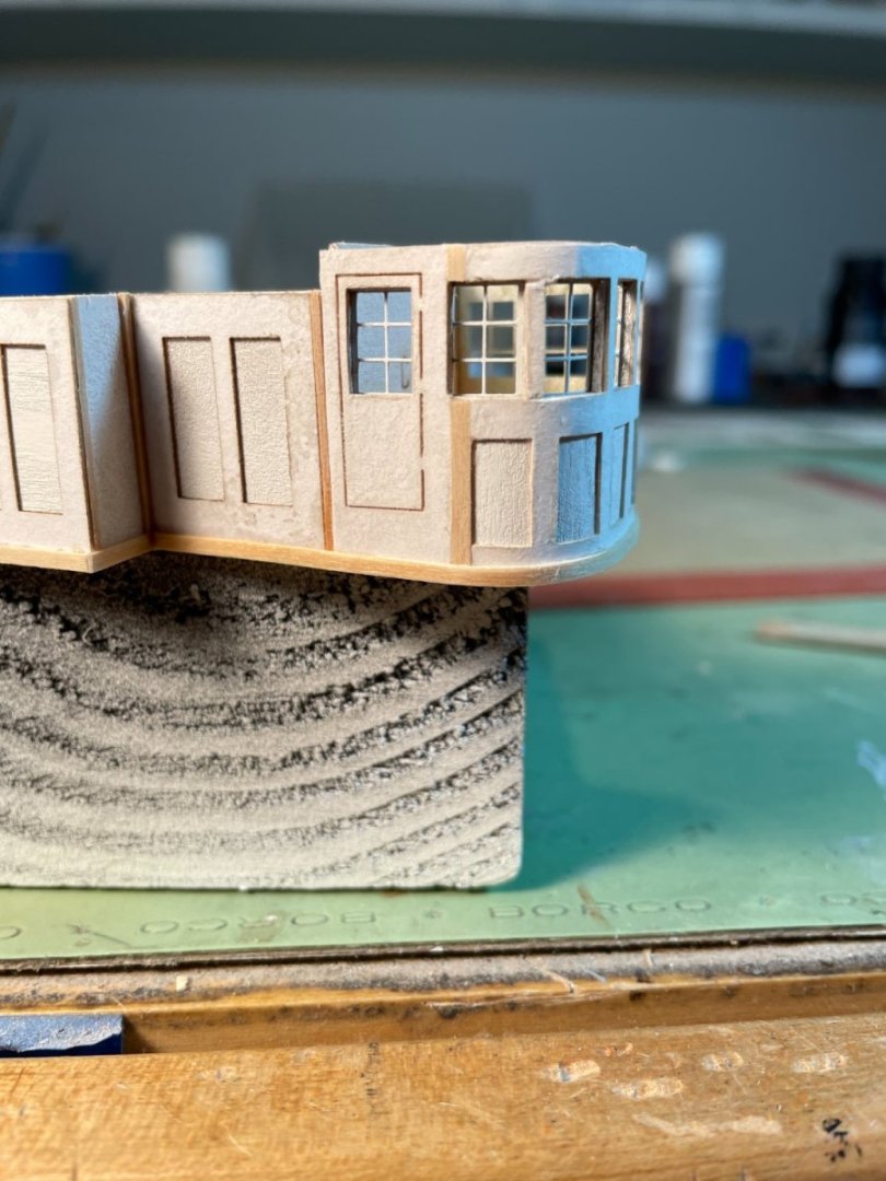
Although I did not have a problem with the Photo-Etched pilothouse window frames fitting I did have an issue with the cardstock panel that wraps around the exterior of pilothouse. In the second photo down you can see that the door and the first window cutout do not match up with the wood cutout underneath. My fix was to cut the door off right at the window frame opening and move it back. I also removed the first window mullion and moved that back also. I then fill the gaps with small pieces of wood. I did this on both sides of the pilothouse.
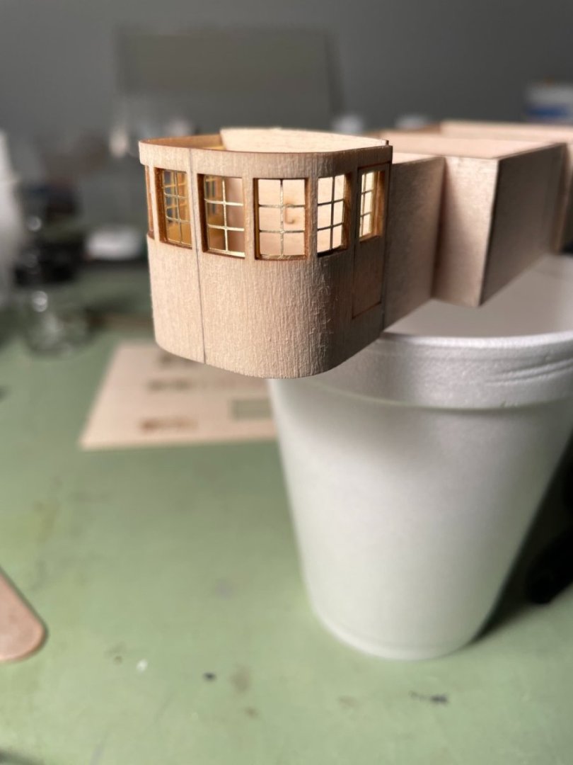

Cardstock door and window relocated.
-
-
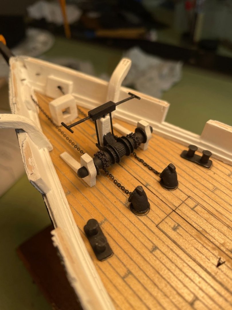
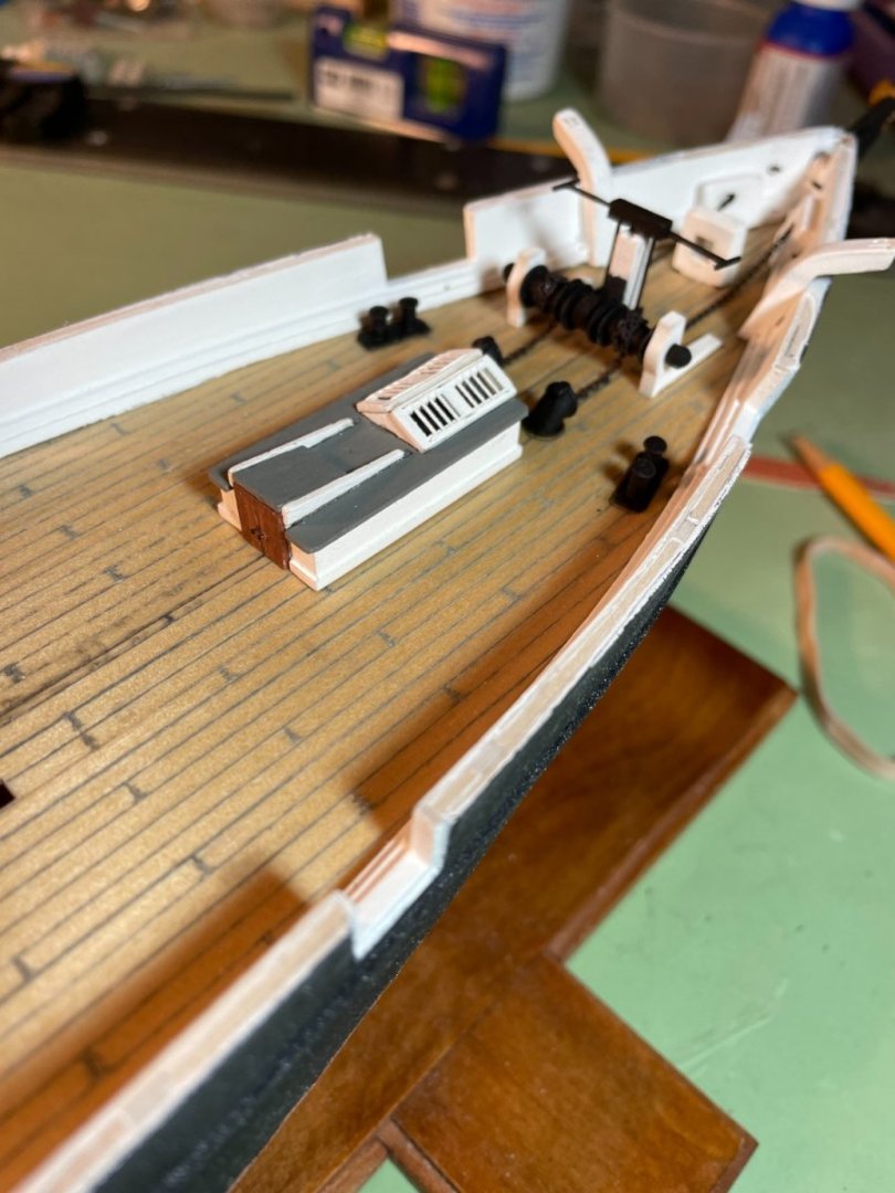
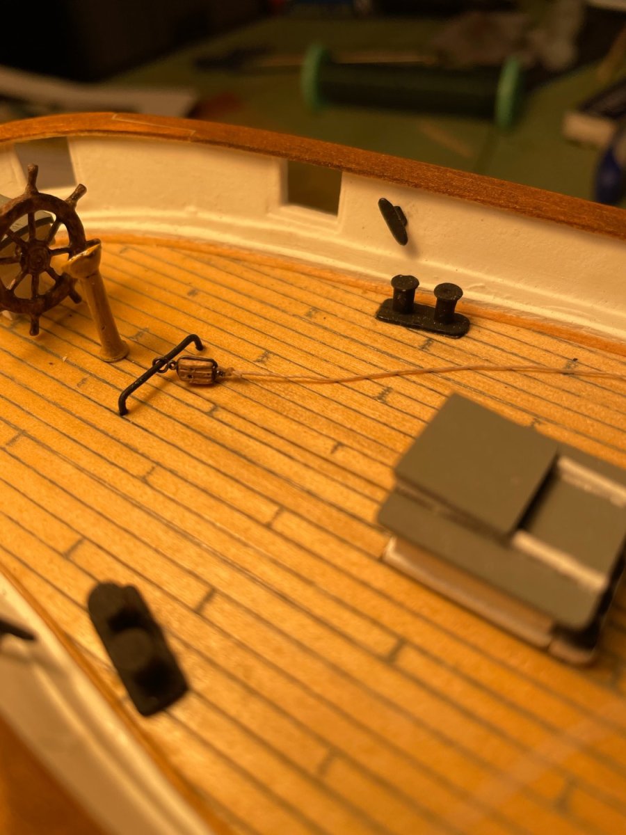
Populating the deck:
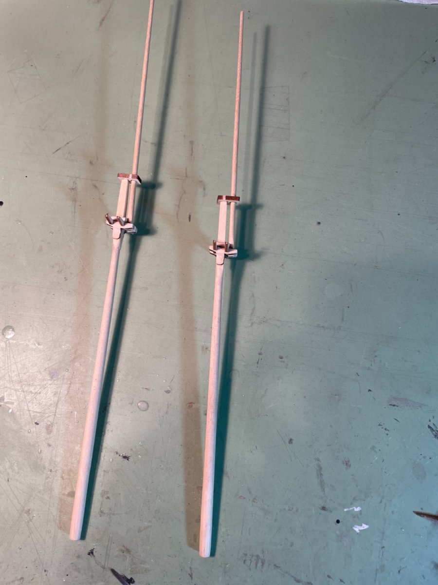
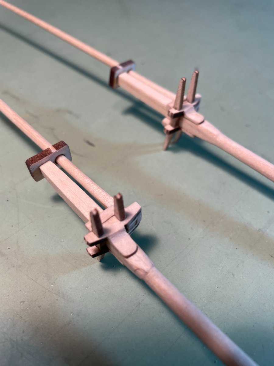
The inner hawse pieces, the bowsprit step, the catheads and windlass assembly were all installed as per the instructions. I added a few extra details to the windlass assembly not included with the kit including a crossover bar with handles, the purchase rods and a pawl. I know the handles are usually stored but I just decided to show them on this ship (or until they get broken off).
Companion way A was assembled and added to the deck.
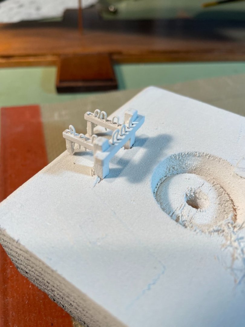
Fore mast bitts:
After assembling the pieces of the fore mast bitts an before painting I filled the holes with pieces of wire to keep them from getting filled with paint.
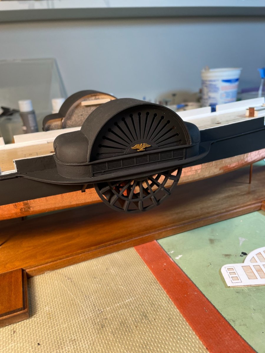
Finally the upper paddle unit was glued in place.

- Canute, ccoyle, GrandpaPhil and 1 other
-
4
-
-
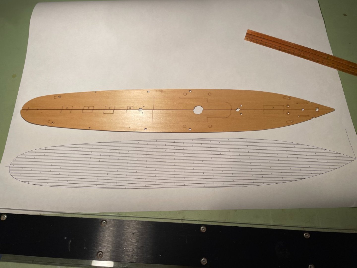
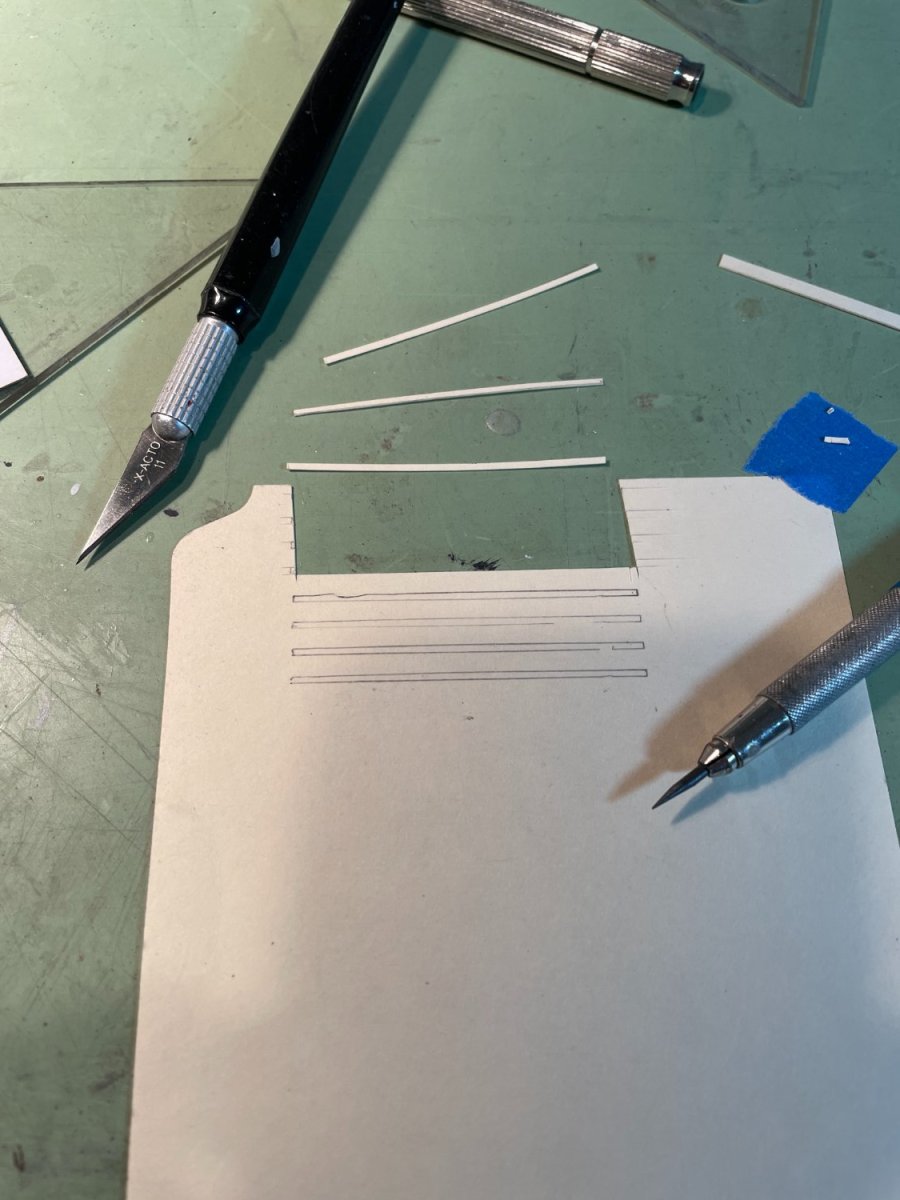
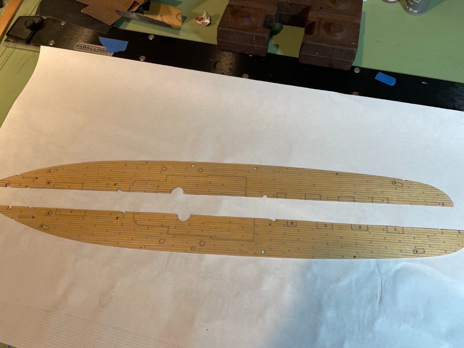
The Deck
Since the deck comes in two pieces instead of individual planks I decided to embellish it a bit by scribing the pieces to simulate planking. I used the same procedure that I used on my pilot boat build where the deck pieces were given four coats of polyurethane and then scored with a steel point. The deck was then painted with an acrylic paint and wiped off also most immediately. Prior to the scribing the deck pieces they were dry fitted in place to insure they fit. After having a little difficulty fitting the deck in beneath the spirketting board the one thing I would do differently is not install it until after the deck is in place. The only reason I can see why you would install it before the deck goes in is so it can be painted. For the planking layout I decided to use a 10" wide plank with a three butt shift. I then drew up a scaled representation of what the deck would look like.
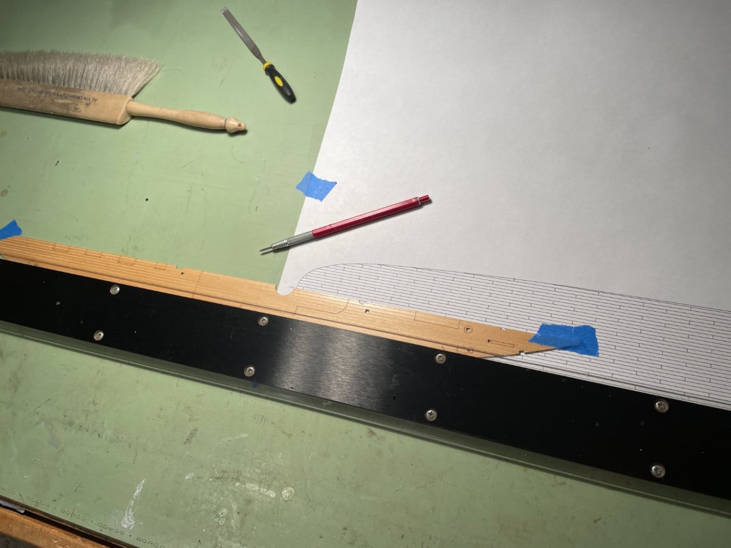
Each deck half was taped down adjacent to the deck layout and scribed.
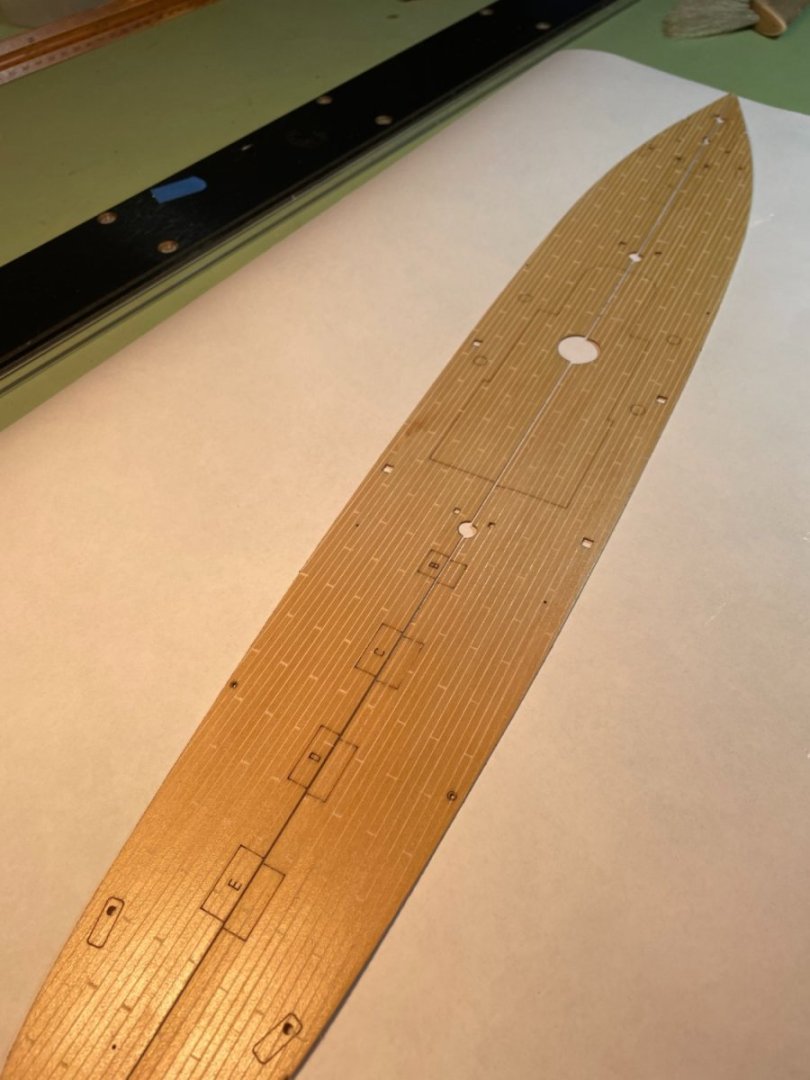
Both halves scribed.
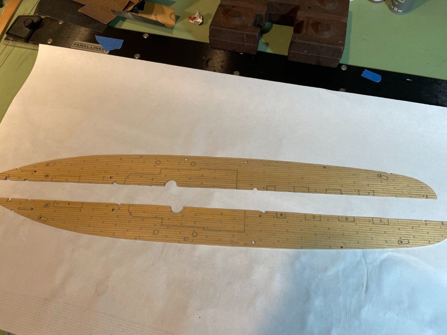
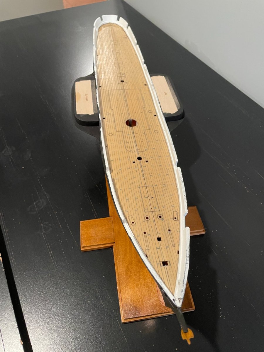
Paint applied and wiped off.
The decking was then glued in place.

I also finished the base and mounted ship.


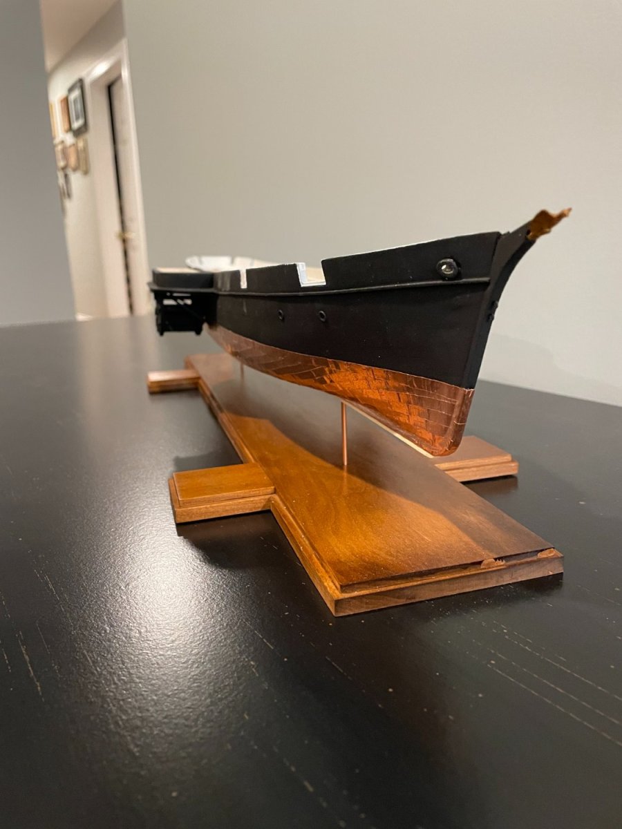
USCG Harriet Lane by _SalD_ - Model Shipways - 1:96
in - Kit build logs for subjects built from 1851 - 1900
Posted
Thanks druxey, I did finally use a small drop of ca glue at the pin location after tying the lines to keep them from coming off.