


_SalD_
-
Posts
757 -
Joined
-
Last visited
Content Type
Profiles
Forums
Gallery
Events
Posts posted by _SalD_
-
-
I'm not exactly sure how a kit can be more of a poor choice if it has bad, difficult wood and crappy instructions, short of pointy wood dowels leaping out of the box and repeatedly stabbing you in the face every time you sat down to work on it. So yeah, I'd say reconsideration is a good plan.
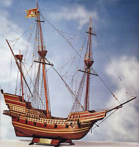
Are you just looking for something galleony or were you interested in that specific kit for some reason? If you're in mood for galleon and race-built is ok, I recently purchased the Victory Revenge and it's excellent.
vossiewulf,
That's quite the visualization... pointy wood dowels leaping out of the box and repeatedly stabbing you in the face


I had thought I was ready to try a scratch built model but I think I need to fine tune my skills a bit more before jumping onto that band wagon. Also while building a case for my U.S.S. Syren and really taking some time to look at all the work I had done on her I sort of got bit by the rigging bug again and decided to build another sailing ship. I'm basically looking for a masted sailing ship that's somewhat different than the one I just finished. I'll take a look at the Revenge.
- mtaylor, Canute and Harmstronginga
-
 3
3
-
-
-
-
Hello all,
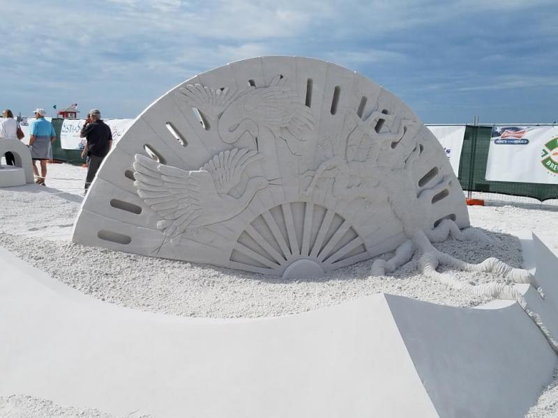
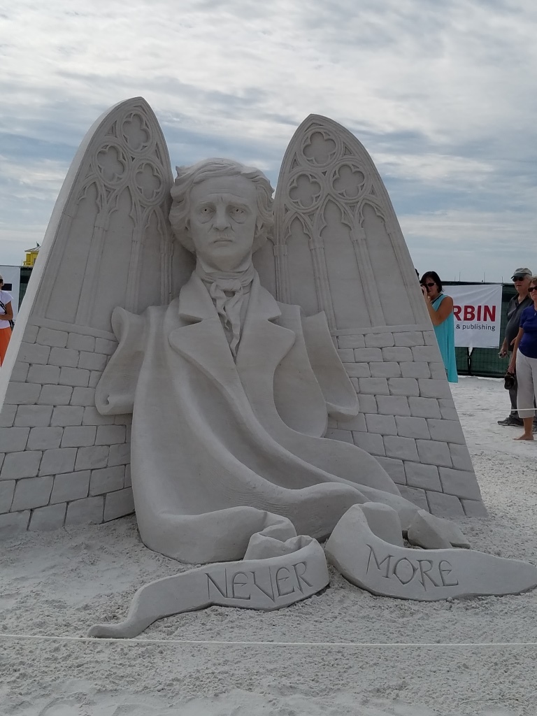
Back from vacation and finding it hard to get back into drafting up the Armenia, perhaps after the holidays. There is something from our stay in Florida that I would like to share. There was a sand sculpting competition at the beach across from our place and it's the first time we were down there when they had the event. I have to say I was truly impressed by with the amount of detail put into these sculptures. All the sculptures are 7 to 8 feet high. If you would like more information here's the web site: https://www.siestakeycrystalclassic.com/
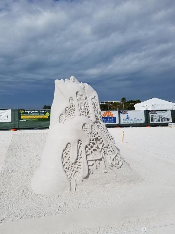
Just a few of the dozen or so sculptures

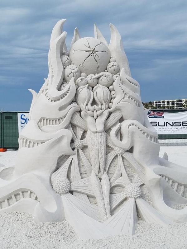

First prize winner


-
-
-
It’s been a while since my last post. It just seems I’m busier now after retiring than I was when I was working full time.
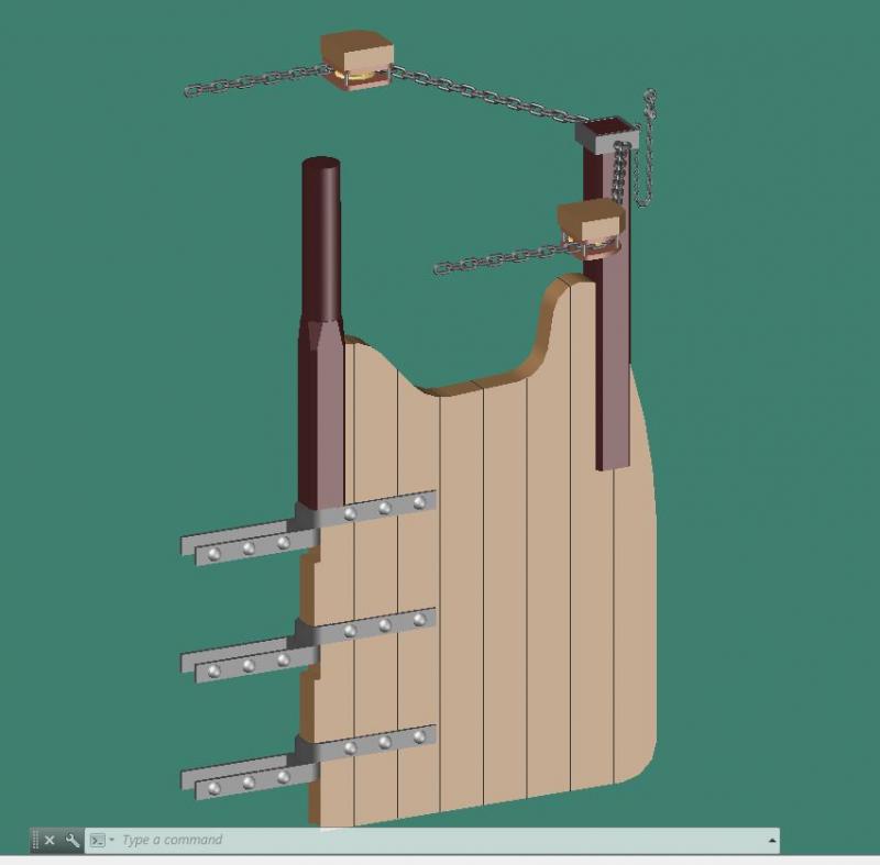
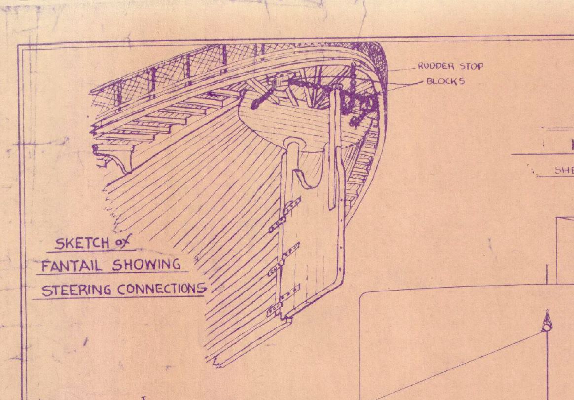
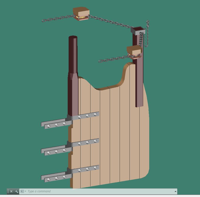
Working on the rudder to try and finish up the hull.
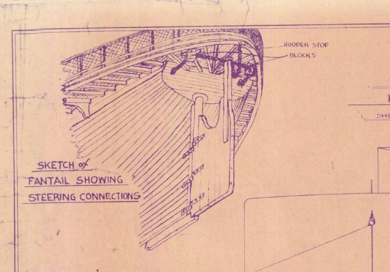
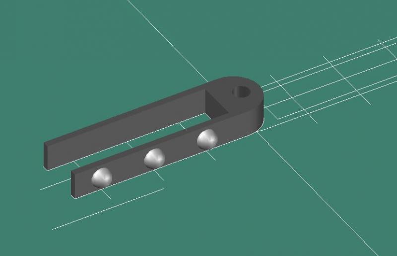
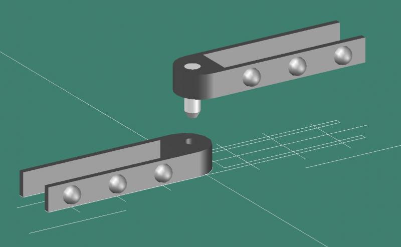
Started with the gudgeons and pintles
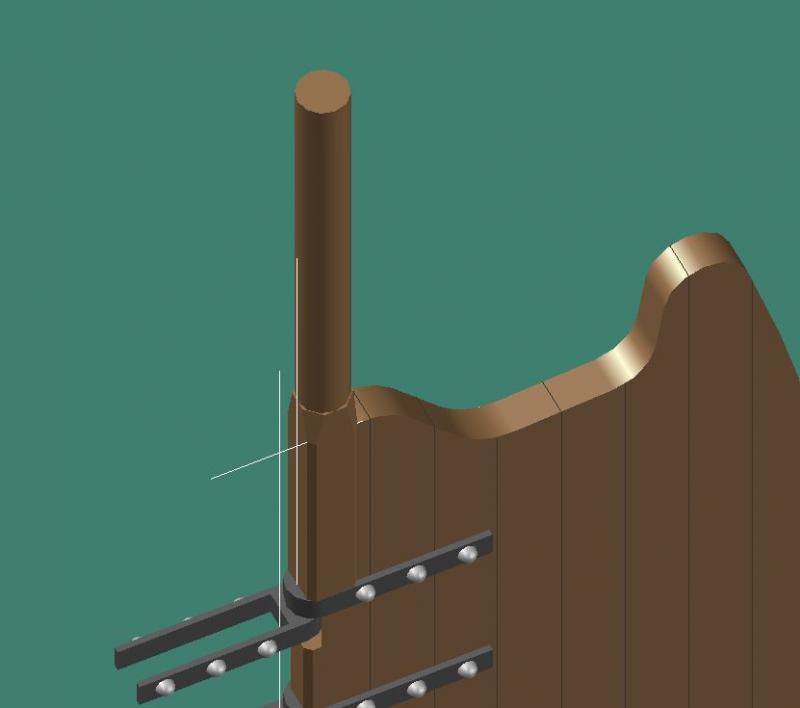
Next was the rudder itself. It appeared to be constructed of individual timbers.


Rudder post and steering post added

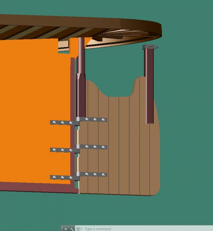
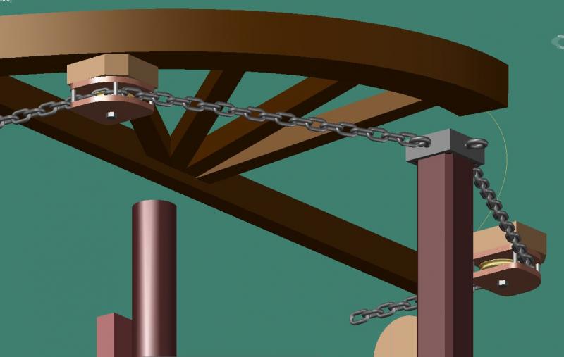
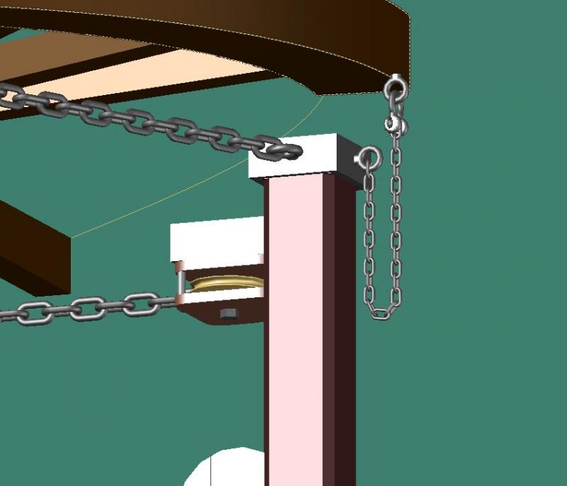
Finally the steering chains and rudder stop chains were added. Fortunately I found a ‘lisp’ program, which runs inside AutoCAD that actually draws the chain links along an established line.
-
-
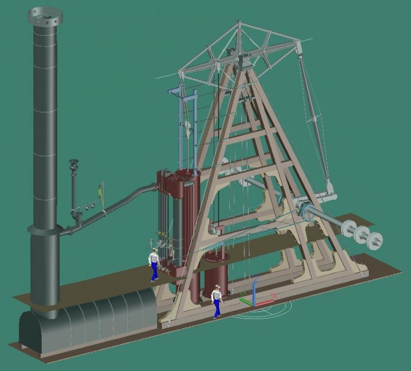
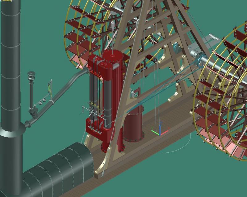
To put things into perspective I added a couple workmen to give an idea of how big these engines were. The upper figure is on the ship's main deck and the lower figure is below deck. I cannot take credit for drawing the 3D man, I borrowed them from my former place of employment. The person is roughly 6 foot tall.

-
Elijah, it's easier than it looks with cad software. First you make one, rivet or nut, then just copy it as many times as you like. If their in a circular pattern there is a command called 'Array' which will evenly distribute copies of an object in a circular pattern around a center point.
-
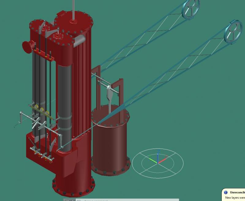
The engine is made up of a few major parts.
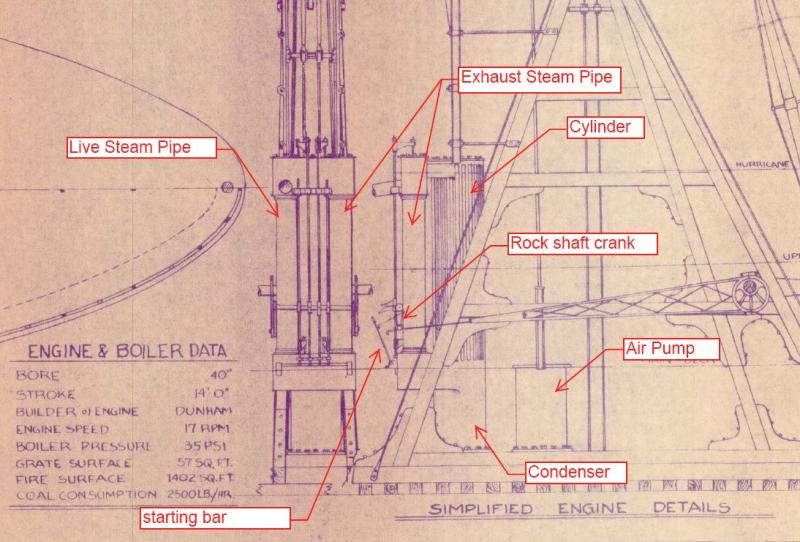
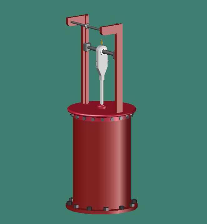
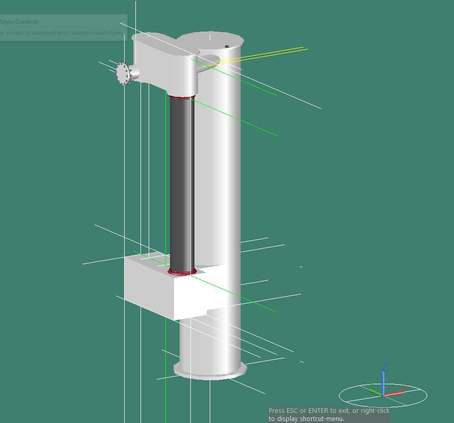
The first part that I modeled was the air pump. The air pump was connected to the condenser and was used to draw off the condensed water and steam vapor. This was fairly simple to model as a cylinder with a piston rod. The air pump was operated by the two slimmer connecting rods coming down from the walking beam at the beams quarter point.
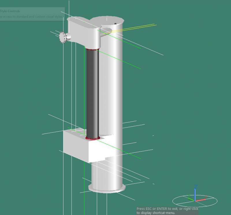
Next I started on the main engine which is comprised of the condenser, cylinder for the main piston rod and the live steam and exhaust steam pipes.

Next I modeled the valve lifters for the live steam and exhaust steam.
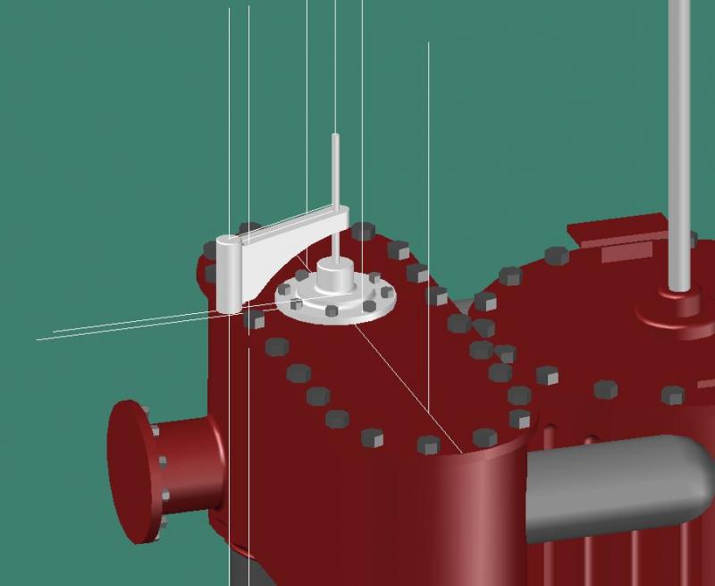
The valve actuating mechanism consisted of a set of large, curved cams called “wipers” which worked against followers called “toes” which were affixed to vertical rods going to the steam and exhaust valves at the upper and lower ends of the two cylindrical vertical steam pipes. The drawing of the engine did not clearly show how these cams were laid out but I did find a good reference. It was on goggle books called “Marine Boilers; Marine Engines; Western River Steamboats”
Even with this diagram I still ran into a little interference with the cams. It’s not clearly shown in the diagrams but I believe the outer cams must have had and offset to operate correctly.
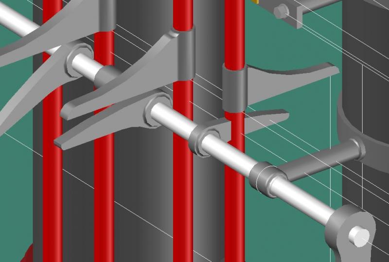
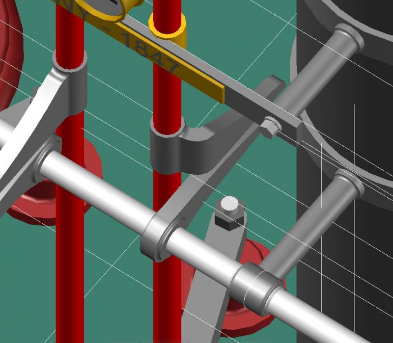
Completed valve actuating mechanism. The lower smaller cams with the starting bar was used by the engineer when first starting the engine either forward or in reverse. The rock shafts were two separate shafts supported in the center by a common bushing.
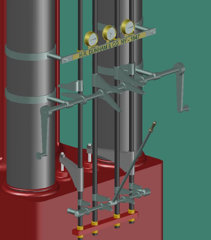
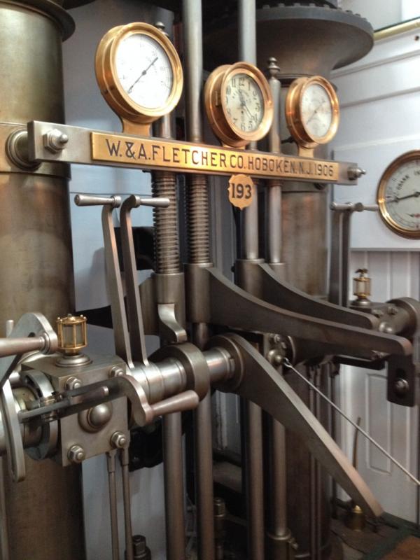
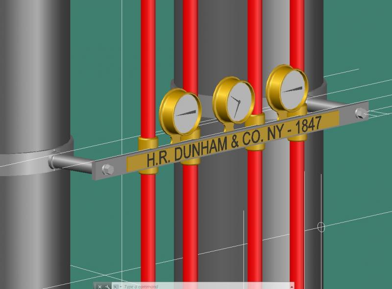
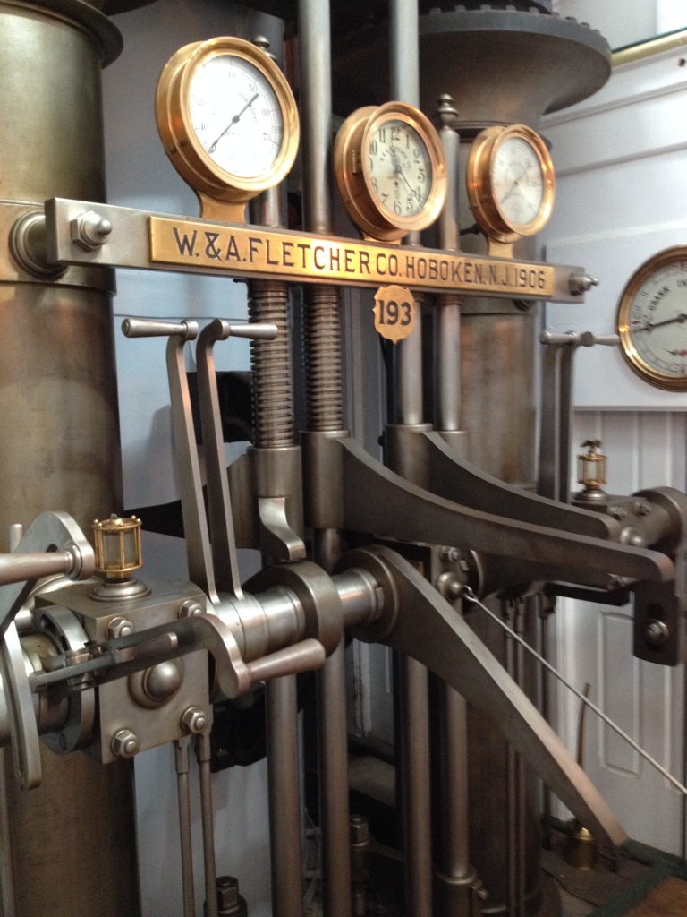
The pressure gauges and clock layout was plagiarized from the Ticonderoga.
Engine, air pump with eccentrics
Engine in place
-
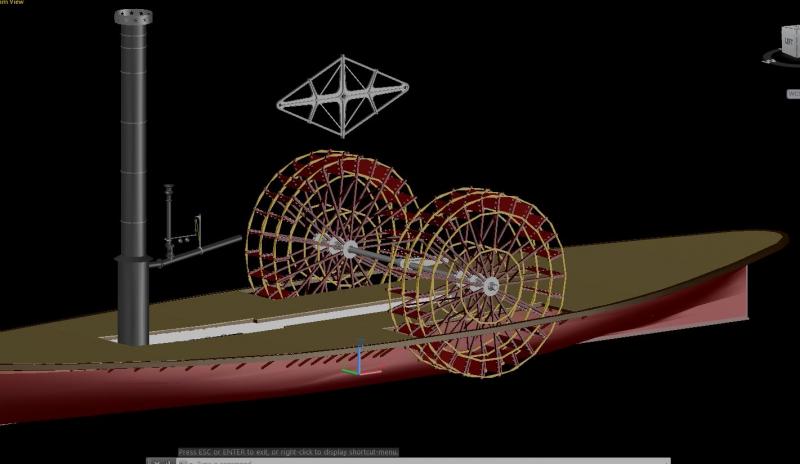
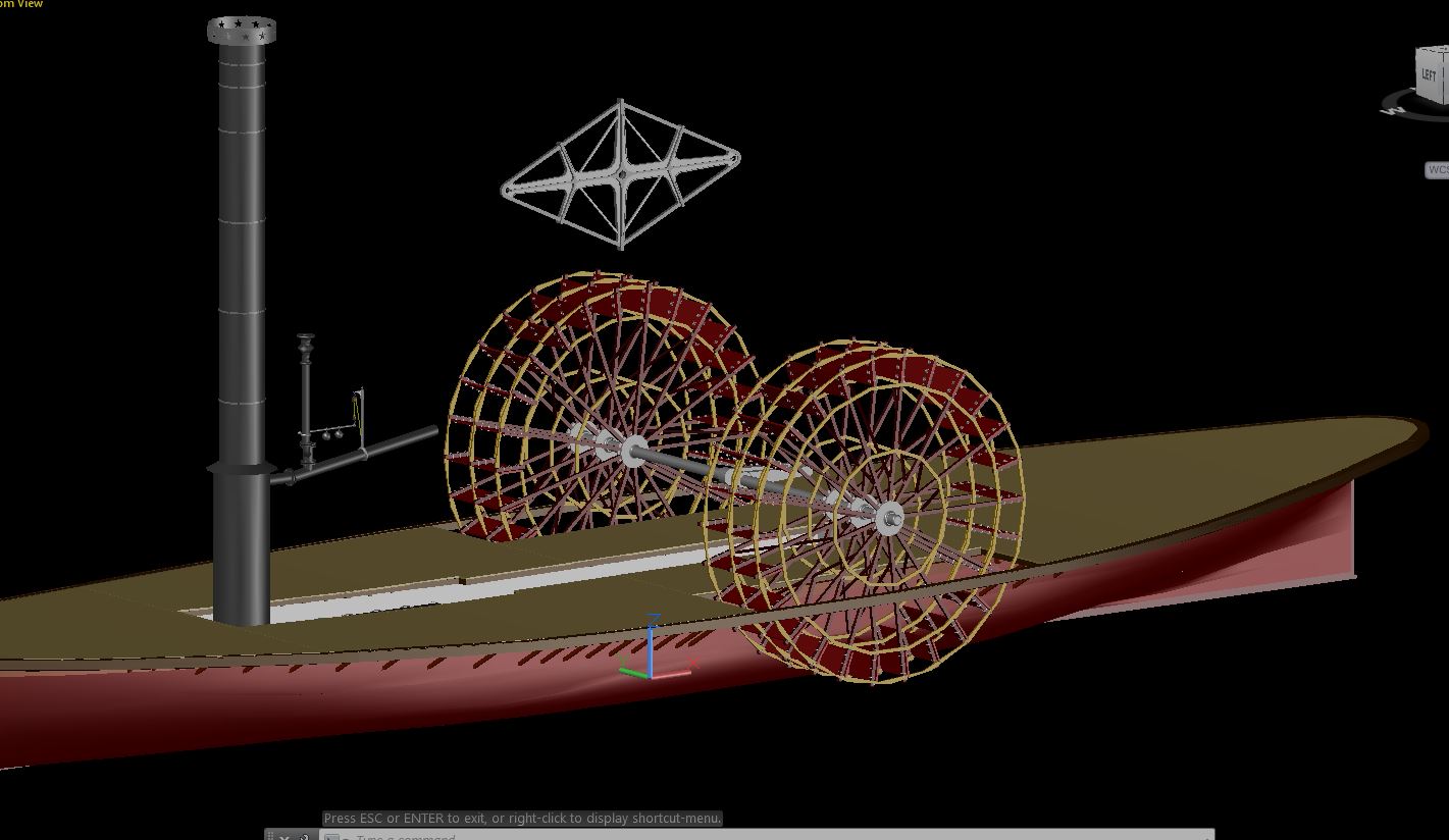
There were eccentric rods on either side of the engine that once the ship was under way would be engaged onto a rock shaft which operated the steam intake and exhaust valves (more on those to come). The eccentrics are connected to the paddle-wheel shaft and have off-centered hubs which produce a back and forth movement in the eccentric rod.
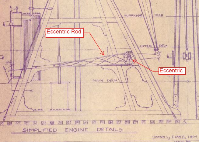
Eccentric
This is how I believe the eccentric rod mounted to the eccentric.

Eccentric pair
Mounted to the paddle-wheel shaft.
-
-
Thanks Wayne. I started this 3D model to help me build a scratch model of her but I think I've gotten a little carried away. Some of the parts I'm detailing I could probably never replicate because of their size but it's fun to do and I am learning a few new things.
-
After the frame I started work on the engine’s connecting rods and please forgive me if I don’t use the correct terminology for some of these parts as I’m not a machinist or ME, so please, feel free to correct me.
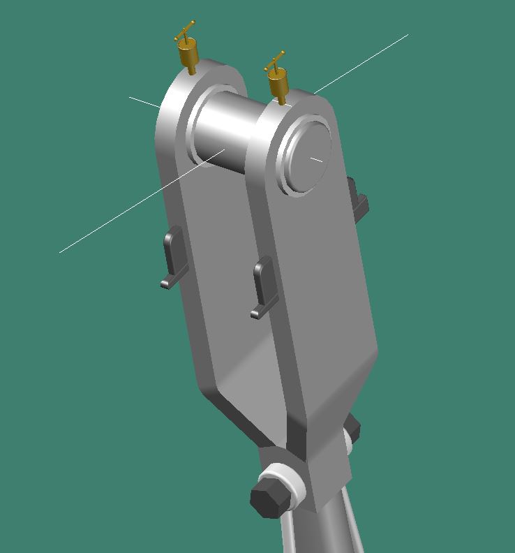
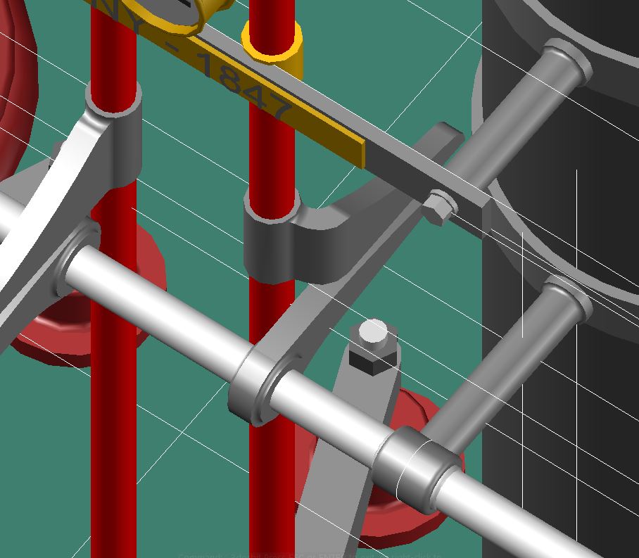
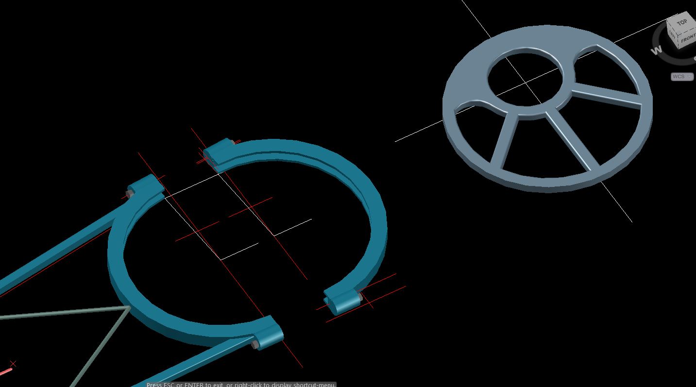
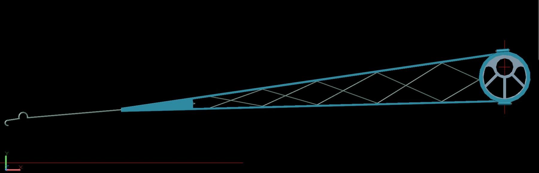
The first one is the braced connecting rod that links the walking beam to the paddlewheel crank. This wrought iron rod is approximately 30’ long by 10” in diameter and is stiffened at its midsection by supplementary rods which bear against braces affixed to its midsection.
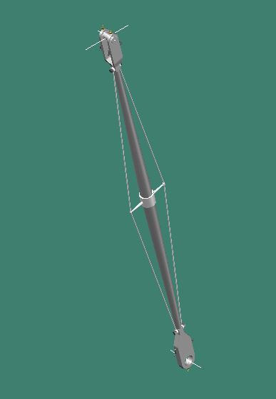
The bearings were of the plain type and made of brass or bronze. The bearing would be adjusted by means of tapered gibs. What I’m not too sure of is the function of the two brass fitting shown on top of the bearings that you can see in the pictures I took of the Tiaconderoga’s connecting rods (previous post). I’m thinking they’re some kind of grease fitting to lubricate the bearings. Not sure of their name.
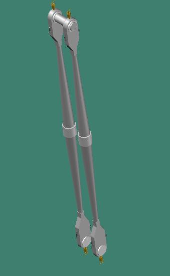
The next set of connecting rods are located at the other end of the walking beam and connect the beam to the crosshead which connects to the piston rod of the engine. These rods are roughly 10’-6” long and 6” in diameter.
Crosshead guide which sits on top of the engine's cylinder and is braced back to the frame.
Crosshead guide with connecting rods.
The next set of connecting rods are for the air pump. These two slimmer rods are connected to the beam close to its quarter point.

All rods in place.
- hexnut, mtaylor, Ryland Craze and 5 others
-
8
-
Wayne, thanks for the reference. I always enjoy studying the old engineering reference books, they're so much more simplified than today's text books since it was all hand calculations and not the pages and pages of computer generated calculations.
I thought the beam must have been made in different pieces but just wasn't sure how it was pieced together. Your reference and explanation helps a lot.
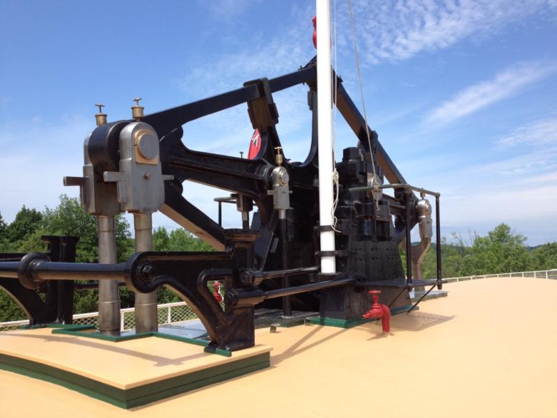
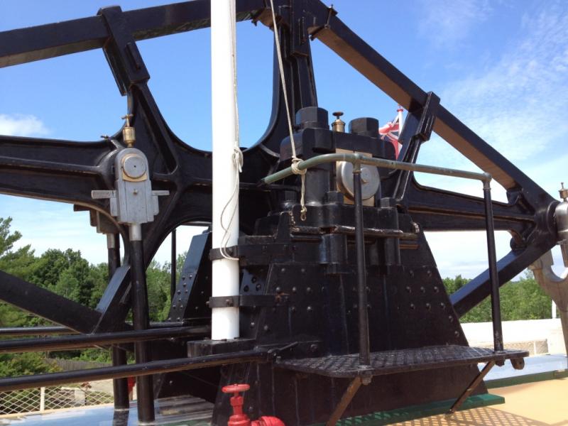
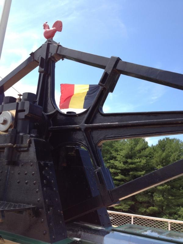
I took a few pictures of the walking beam on the Ticonderoga at the Shelbrune Museum in Vermont this past summer, now it makes more sense.
-
-
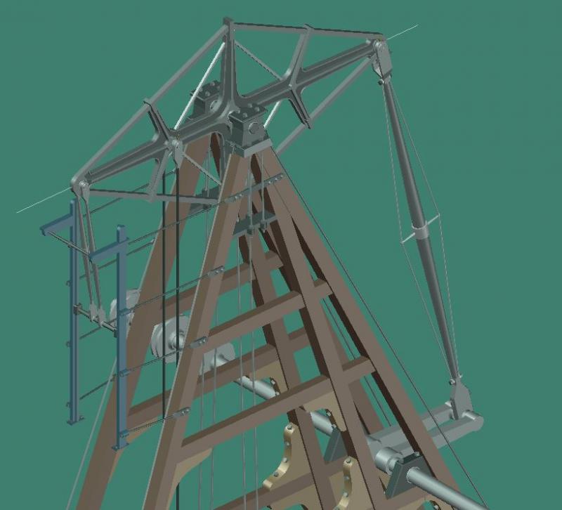
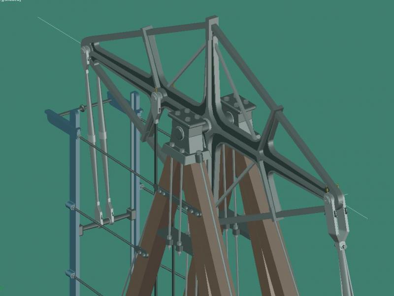
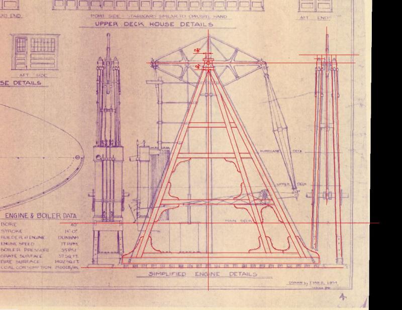
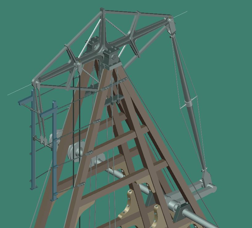
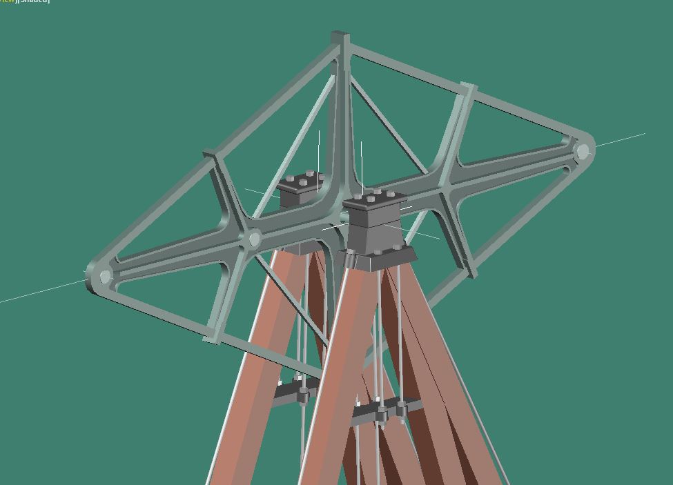
I started working on the walking beam engine by first modeling the walking beam. The dimensions were taken by scaling the drawing.
Building the model laying flat
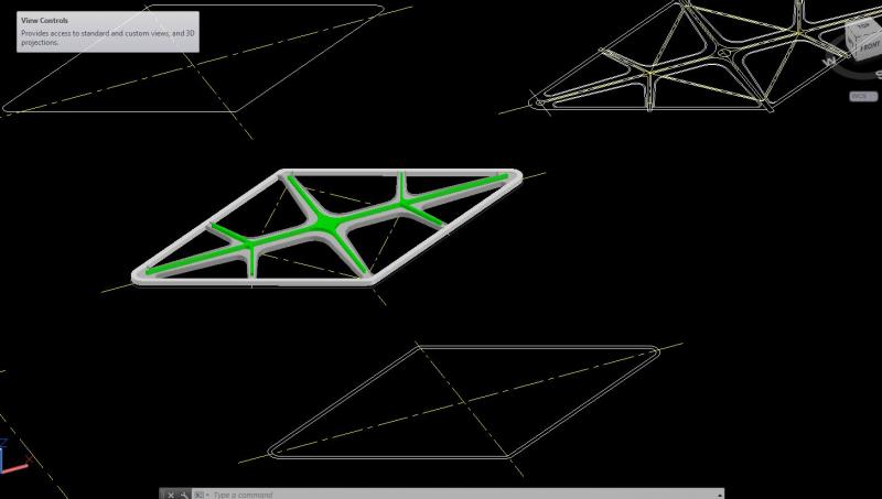
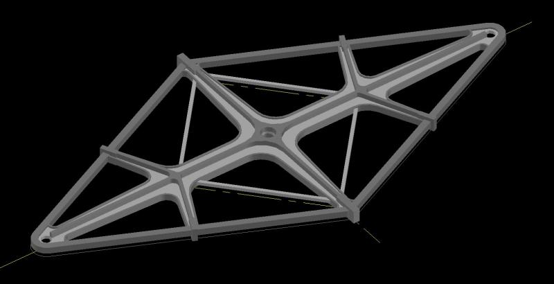
Nice thing about 3D models is that you can build parts in any order and put them in place.
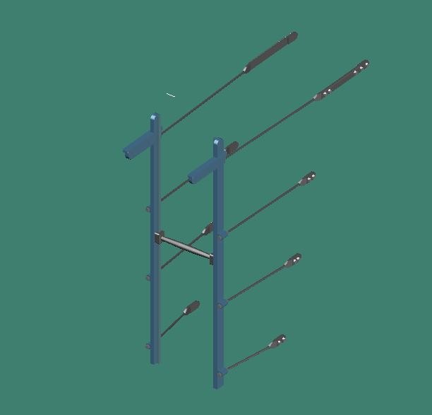
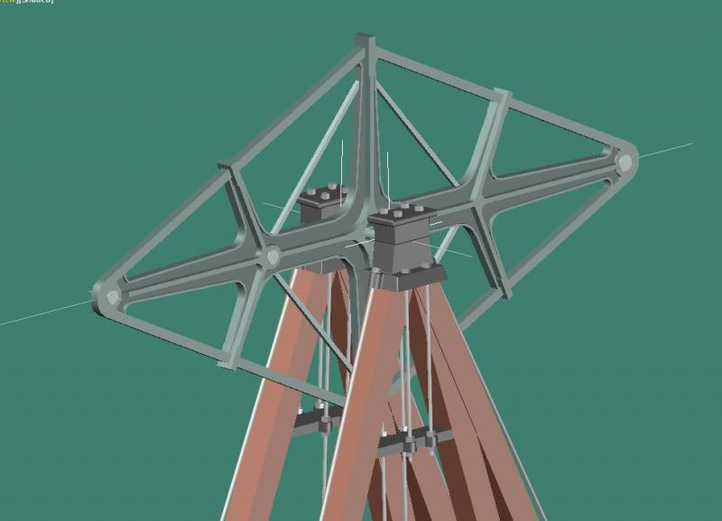
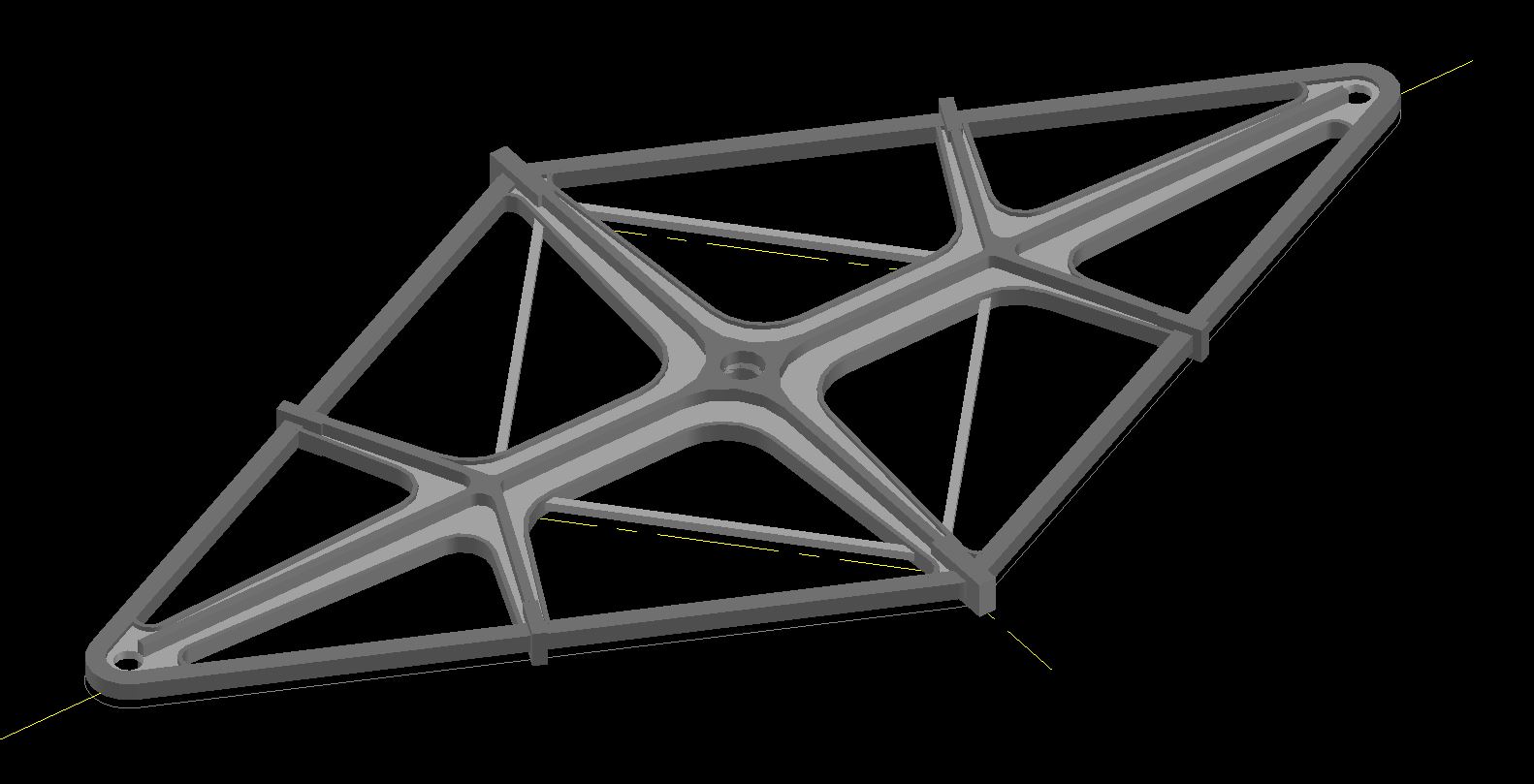
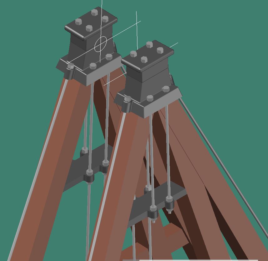
Next I modeled the support frame for the beam based on the drawing dimensions.
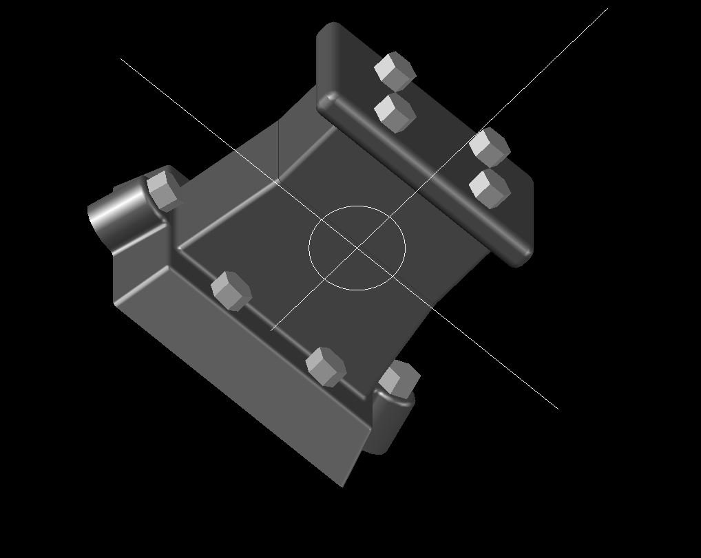
Bearings at the top of the frame that supports the beam.

The main vertical members are 12”x12” timber. For the bracing tie rods I used 1 ½” diameter rods.
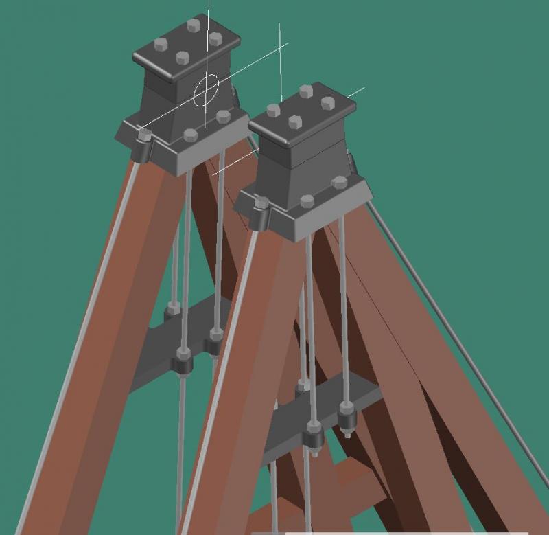
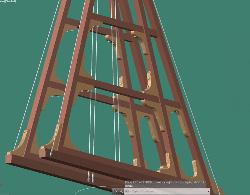
beam in frame, still need to add the main support shaft.
As a side note I made a little virtual walkthrough around the relief valve that I posted but you couldn't play it, so I deleted it. I guess you can’t post videos here.
- GrandpaPhil, mtaylor, WackoWolf and 7 others
-
10
-
-
-
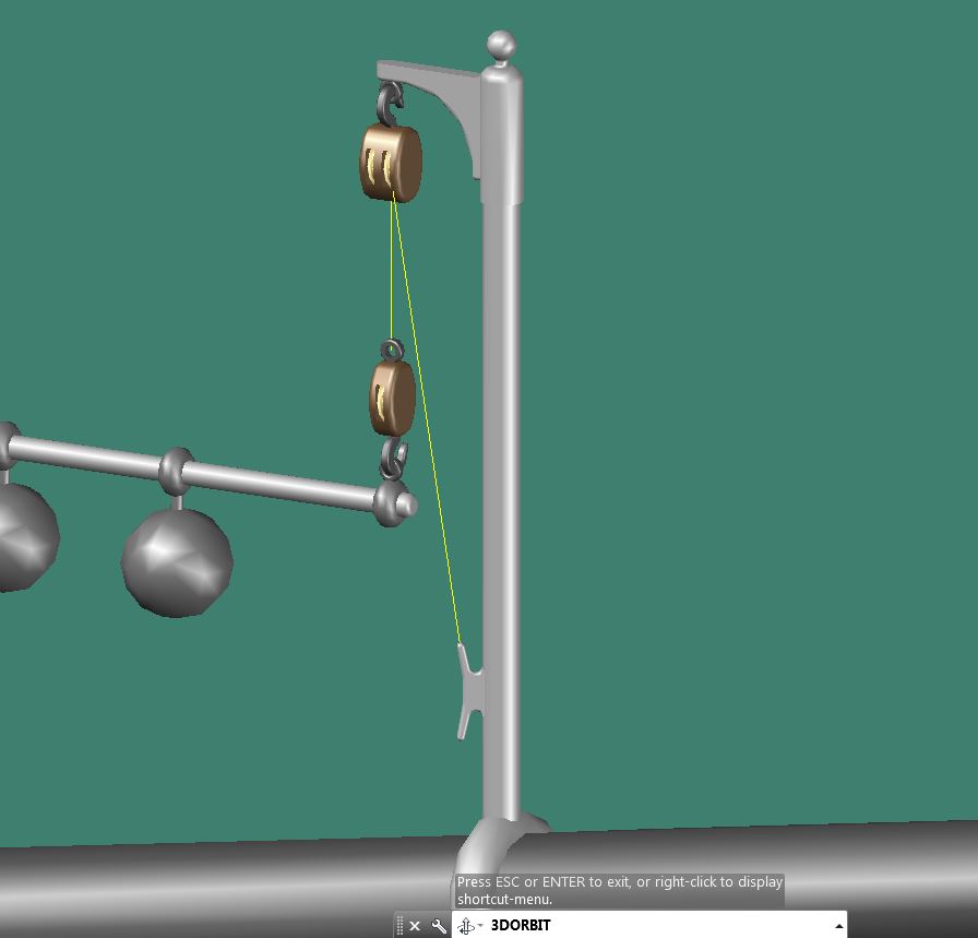
Wayne, thanks for looking and all good questions. They probably did use the valve to blow off steam, bypassing the engine, for both reasons you mentioned. I didn't notice until you asked but the outside ball does scale a bit smaller than the inside one. I'm not sure if that was intended or if they were suppose to be equal. It probably did work like an arm scale where the weights are movable to get the correct relief pressure they wanted.
As for the rope, straight I can do, going around the sheave... a different story.
-
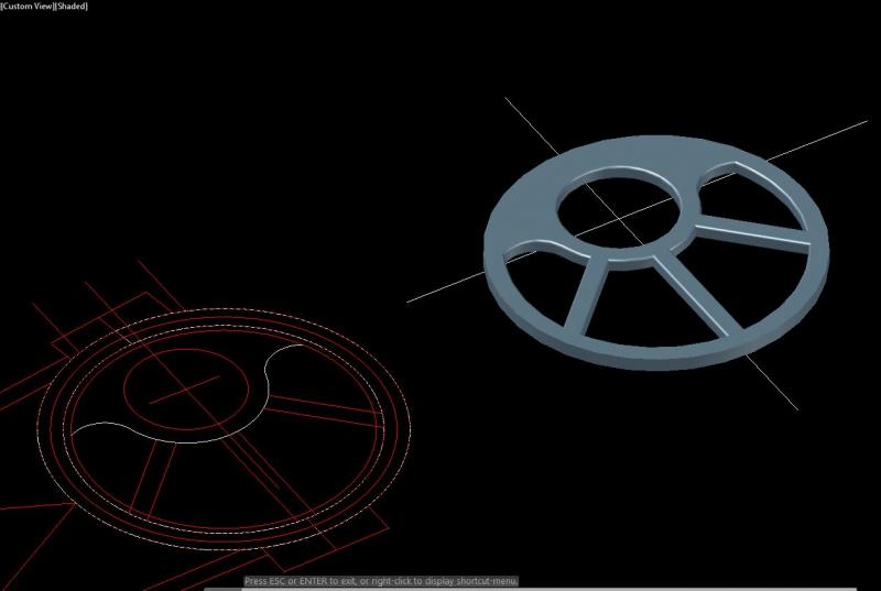
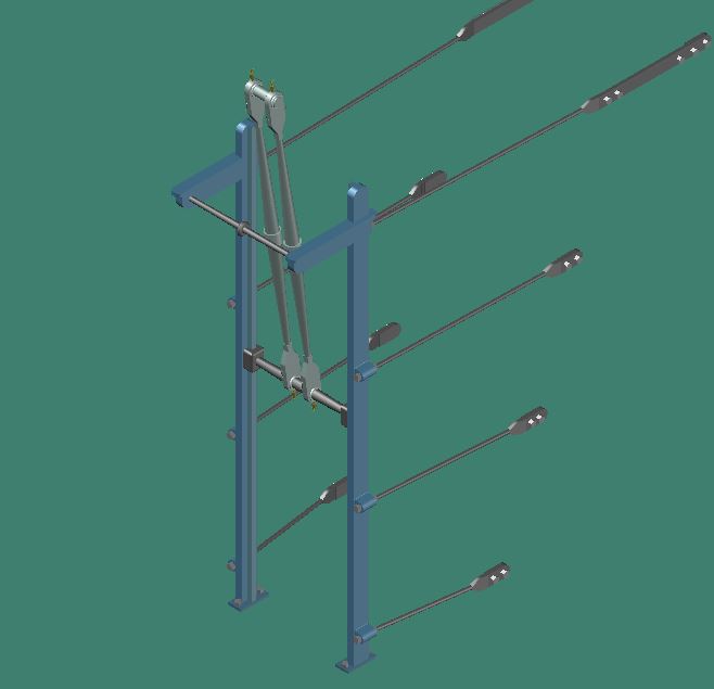
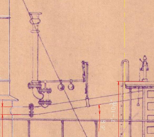
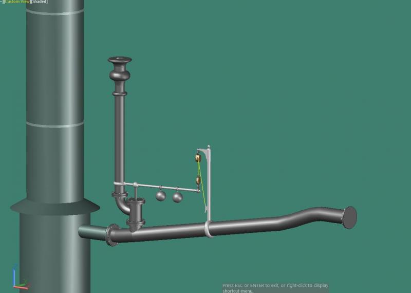
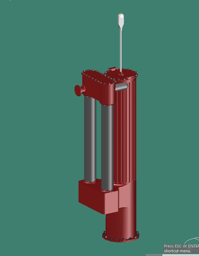
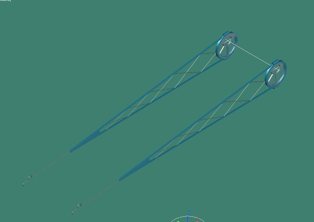
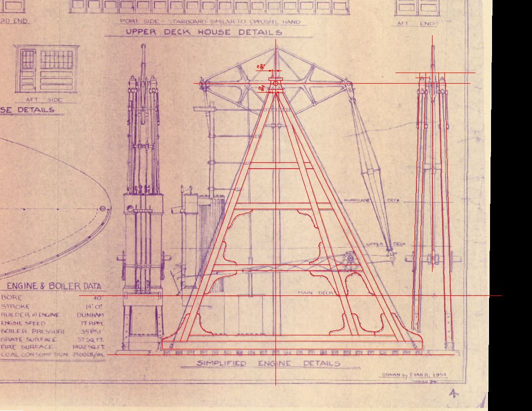
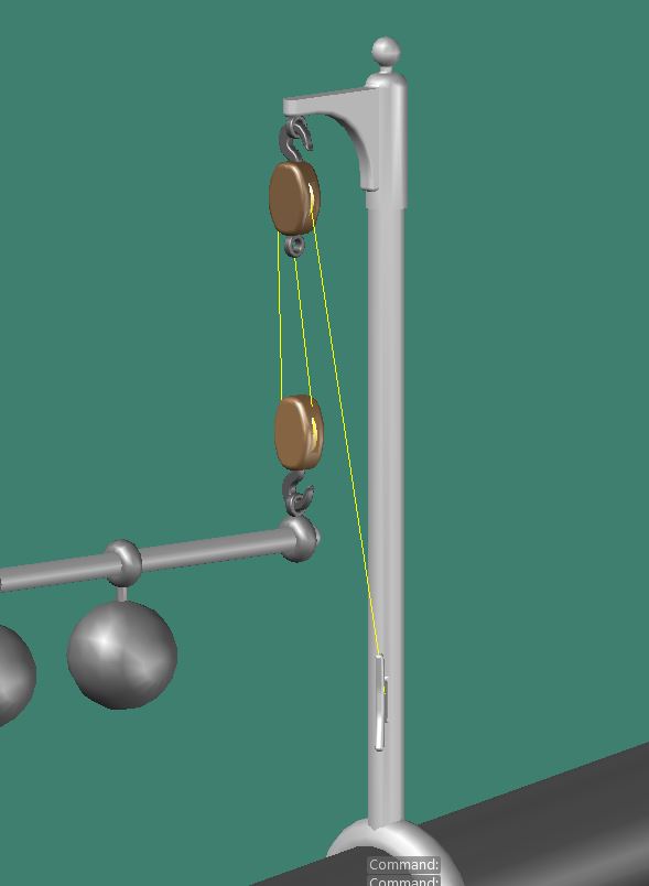
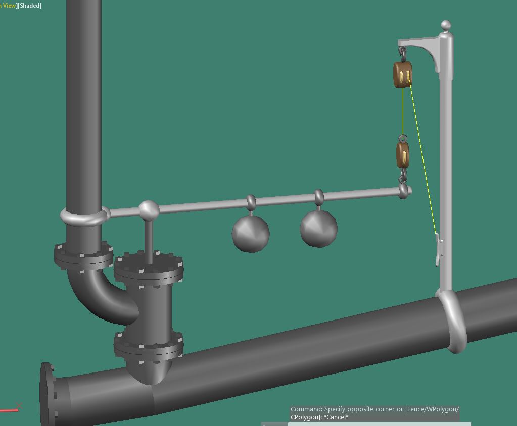
The next part I worked on was what I think is some sort of pressure relief valve in the main steam line from the boiler to the engine. From the drawings it appears to be a weighted lever with a plunger type valve that if too much pressure builds up would be forced up allowing the steam to be bypassed to a blow off stack. I’m not too sure what the purpose the block and tackle at the end would serve other than setting how far the plunger would need to rise before the steam was bypassed.
Original drawing layout
Modeled relief valve
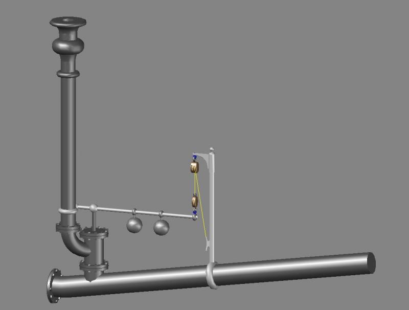
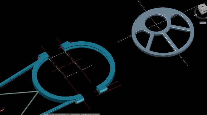
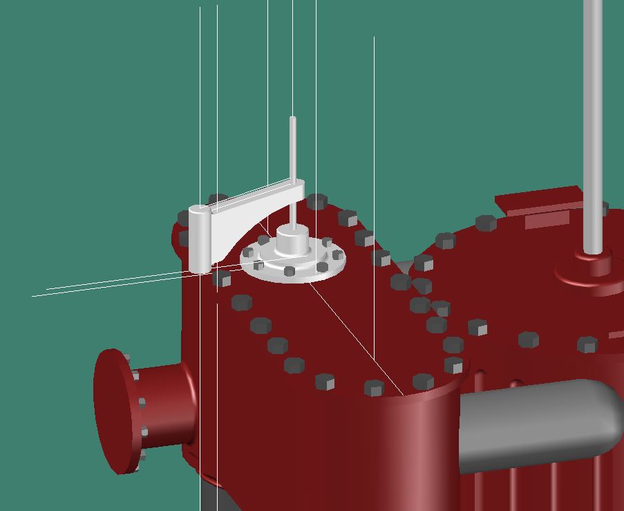
Weighted lever.
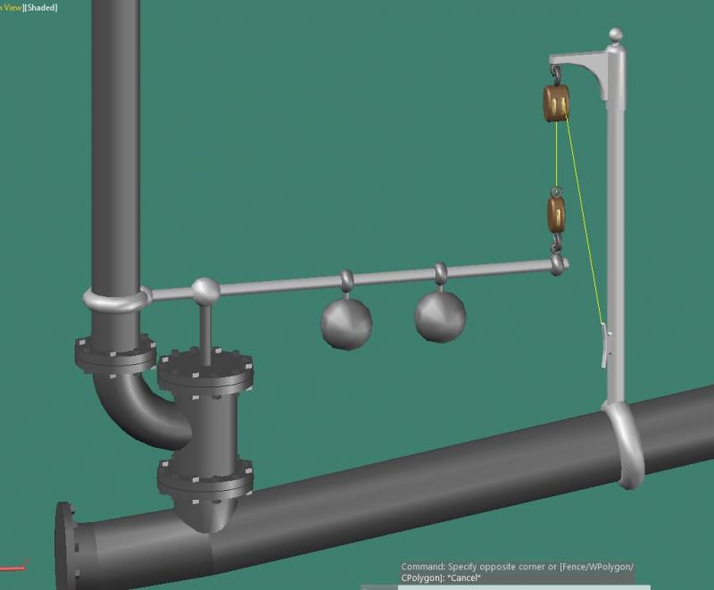
Block & Tackle The rope in the blocks are just two separate lines, I haven't tried making realist looking rope reeved through the blocks yet (well, actually I tried but the results weren't pretty).

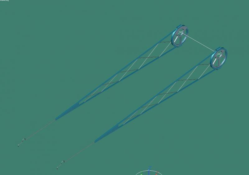
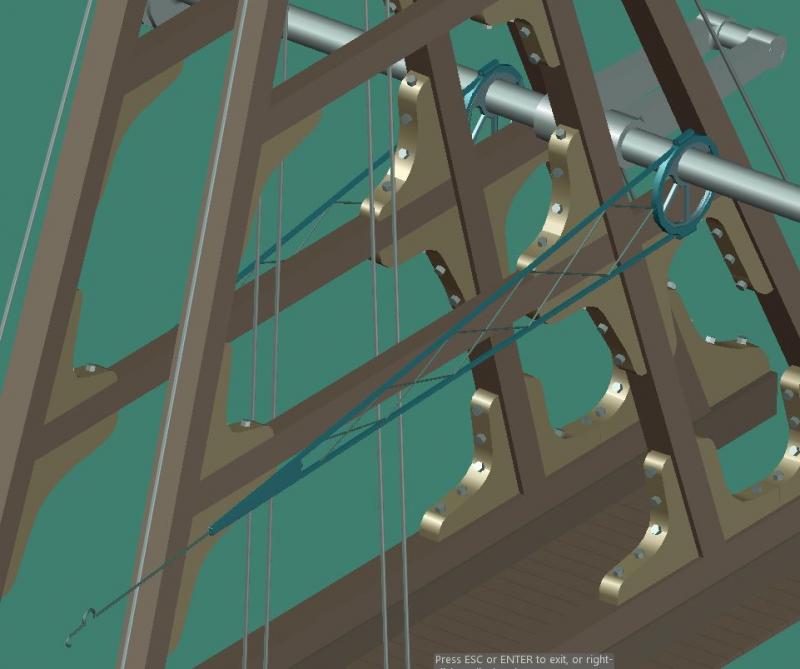
Valve in place off of stack
-
Hi Sal,
I meant to ask when at the meeting, once you complete the CAD, are you going to build it with "sticks and bricks"?
Best,
John
Yes, that's the plan, I figure it's easier to work out the kinks on the 3D model than the actual model.
- Elijah, Landlocked123, mtaylor and 2 others
-
5


Recommendation for Good Textbooks on Basic drafting.
in CAD and 3D Modelling/Drafting Plans with Software
Posted
Nathan, For the style of text it will depend on what font's are available with the cad software you are using. I use Autocad and use their 'simplex' font for the majority for the dimensions and text. As far as text height I prefer text that is 3/32" high for dimensions and text, for titles I scale the 3/32" text up by 1.5 or 2 times.
For drafting the ship I've found using a scanned drawing as an overlay works well. It's also easier to pull dimensions off the scanned drawing than the hard copy. these are just my opinions and seem to work well for most cases.