
MORE HANDBOOKS ARE ON THEIR WAY! We will let you know when they get here.
×

MEDDO
-
Posts
1,871 -
Joined
-
Last visited
Reputation Activity
-

 MEDDO reacted to xken in USS Constitution by xken - Model Shipways - Scale 1:76.8
Finished up the topmast ratlines and and then started on the ladders. I am assuming that there are ladders on each mast up from the crosstrees. What I am not sure of is how they are attached at the lower cross tree. Are they just attached at the lower eyebolts or if there is a block and tackle to tighten the ladder as it stretches over time? I cannot seem to find a detail that shows the lower end of the ladder. Hopefully someone can share the answer.
Now to make a couple of more ladders.
-
 MEDDO got a reaction from mtaylor in Halifax 1768 by MEDDO - FINISHED - Lauck Street Shipyard - 1/4" scale
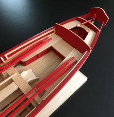
Had to leave off the rudder as I don't want to attach it until the end as I am still moving the ship about too much.
As Bob (Rafine) also had to do on his stem I need to cut out a slot and thin it so the figurehead can fit.
Here is the resin piece provided. Needs a little cleanup.
Almost forgot had to get it sitting down far enough to clear the bowsprit.
Next step to start building up the headrails.
Cheers
-
 MEDDO got a reaction from Ryland Craze in Halifax 1768 by MEDDO - FINISHED - Lauck Street Shipyard - 1/4" scale
Had to leave off the rudder as I don't want to attach it until the end as I am still moving the ship about too much.
As Bob (Rafine) also had to do on his stem I need to cut out a slot and thin it so the figurehead can fit.
Here is the resin piece provided. Needs a little cleanup.
Almost forgot had to get it sitting down far enough to clear the bowsprit.
Next step to start building up the headrails.
Cheers
-
 MEDDO got a reaction from hexnut in Halifax 1768 by MEDDO - FINISHED - Lauck Street Shipyard - 1/4" scale
After a bunch of shaping and cutting away, I am able to temporarily get the rudder in. Next up is making the gudgeon and pintles. Which include soldering and blackening.... Yikes, will be my first time doing both.
-
MEDDO got a reaction from hexnut in Halifax 1768 by MEDDO - FINISHED - Lauck Street Shipyard - 1/4" scale
Rudder time... As usual in this kit it is built up in layers.
With a bit of sanding and glue... (tiller is probably upside down in picture...)
Now we come to a problem. The itty bitty little tiny space on the ship where this big fat rudder is supposed to fit into. Obviously gotta work a bit of shaping on the top half of the rudder and the "rudder hole" (I am sure there is a nautical term for this area).
-
 MEDDO got a reaction from piter56 in Halifax 1768 by MEDDO - FINISHED - Lauck Street Shipyard - 1/4" scale
Small update. Finished the bits so next up is the rudder.
-
MEDDO reacted to giampieroricci in L'Amarante 1749 by giampieroricci - FINISHED - 1:30 - French Corvette
Handle of the helm and chain:
-
MEDDO reacted to Tigersteve in English Pinnace by Tigersteve - FINISHED - Model Shipways
Robert,
I appreciate the compliment on the 26' longboat. Below is the order I placed. I went through the practicum and parts list to determine what I would order to supplement the kit. I did my best to calculate extra material for mistakes. Also, Wood Project Source included extra strips in every dimension. I suppose it was the remaining wood from the sheets they used to mill the strips.
Steve
1/32" x 3/16"x 24" 40 strips for planking and risers
1/32" x 1/4"x 24" 10 strips for floorboards and aft platform
1/32" x 1/8"x 24" 5 strips for inboard planking
1/32" x 1/16"x 24" 6 strips for outboard mouldings and inboard panels
1/16" x 5/16"x 24" 3 strips for thwarts and front platform
1/16" x 1/16"x 24" 2 strips for stanchions
3/32" x 3/32"x 24" 3 strips for oars
1/16" x 3" x 24" 2 sheets for cap rail
-
MEDDO reacted to tkay11 in Triton cross-section by tkay11 (aka Tony) - FINISHED
That's very funny, Niklas, because your build of Le Rochefort made me go back to have a look at it again as a possibility for my next build. I've been scanning the different ship's plans I have before making CAD tracings as part of the process of deciding which to build first (the others being the Brixham trawler Valerian, the Frigate Naiad, and La Jacinthe).
You've seen the interesting discussion about framing the Brixham trawler and I was pleased to work out how to do the framing for that. As I'll be visiting Brixham in June to see the three main trawlers re-built there, I'll have lots of photos to help and that may well help me to finalise the decision. But the step-by-step guide provided by Ed Tosti with the Naiad is very tempting, and Le Rochefort is tempting because the framing is simpler and very clearly presented (as well as being a merchant ship, which I prefer). La Jacinthe is still on my list simply because it's a beautiful ship and I think my wife would prefer it far more than the others!
One of the irritating things about scanning from paper (especially if it's been folded) is the fact that the flatbed scanners have complex distortions which don't allow for simple re-sizing and overlapping if you want a really accurate result, so I have to end up making small sections and re-adjusting. In fact it's the same process as re-drafting on to paper as I have to make a grid and use the measurements of each part of the plans to which I can re-size. The errors are approximate 1mm per 100mm, but variable with both barrel and pincushion distortion, so it's much easier when the plans are provided as pdfs (as for the Naiad) when there's no distortion and only errors of drafting.
Thanks for appreciating the Triton, though! I much enjoyed doing it.
Tony
-
MEDDO reacted to rafine in Halifax by rafine - FINISHED - The Lumberyard - 1:48 - semi-scratch schooner
I've now completed the stern cant frames. These presented two problems. The first was the expected difficulty of cutting and sanding the required angles to get a proper fit. That went reasonably well. The second, however, was more troublesome. The aft most frame did not match the plan and had to be tweaked to get it to fit. it remains to be seen after final fairing and assembly of the stern framing whether this will turn out correctly, or whether I will need to remove it and make a new pair of frames. As I have been doing, I did some rough fairing to get a feel for the fit of the frames.
I'm now working on the bow cant frames.
Bob
-
 MEDDO got a reaction from Blue Ensign in Halifax 1768 by MEDDO - FINISHED - Lauck Street Shipyard - 1/4" scale
So first attempt at silver soldering went ok. Was difficult trying to get the little tubes in the correct orientation to the strip. They kept coming out crooked. It was easy to just reheat it and move em a bit though. Here are the rough gudgeon prior to cleaning them up.
Every day acquiring new skills
-
 MEDDO got a reaction from DocBlake in Halifax 1768 by MEDDO - FINISHED - Lauck Street Shipyard - 1/4" scale
So first attempt at silver soldering went ok. Was difficult trying to get the little tubes in the correct orientation to the strip. They kept coming out crooked. It was easy to just reheat it and move em a bit though. Here are the rough gudgeon prior to cleaning them up.
Every day acquiring new skills
-
MEDDO got a reaction from hexnut in Halifax 1768 by MEDDO - FINISHED - Lauck Street Shipyard - 1/4" scale
Very first attempt at silver soldering. seemed to do ok. Its a little tilted but it seems strong.
-
 MEDDO got a reaction from Tigersteve in Halifax 1768 by MEDDO - FINISHED - Lauck Street Shipyard - 1/4" scale
Thanks B.E. And thanks everyone for the likes.
-
MEDDO reacted to DocBlake in 3D-printing for modellers?
3-D parts are already being produced. My AVS "Patrick Henry" had parts included. I didn't use them for a variety of reasons, but they were actually quite nice. Here's a photo. Parts are available at shapeways.com. Search for "model ship parts".
-
 MEDDO got a reaction from CaptainSteve in US Brig Syren by Gahm - Model Shipways
Looks great. It's wonderful to see what a skilled modeler can do with a great kit.
-
MEDDO reacted to Tigersteve in English Pinnace by Tigersteve - FINISHED - Model Shipways
Welcome aboard. This kit design, although similar to the longboat, provides its own challenges. I suspect planking will be equally difficult. The longboat is a more complex project and very tiny (6 1/2 inch hull). Parts just kept getting smaller as I progressed in the build.
My order from Wood Project Source has shipped. Also, the display case from Kreative Acrylics for the longboat has shipped. Stay tuned...
Steve
-
MEDDO reacted to Mahuna in Kathryn by Mahuna - FINISHED - 1:32 - Skipjack Based on HAER Drawings
Part 12 – Knightheads
It has been almost 2 weeks since my last post. The delay comes from two things: a lot of non-modeling activities and responsibilities; and a lot of time spent trying to work through the correct process for the next elements of the Kathryn build.
Part 11 dealt with the complexity of the stern timbering and my questions on how to proceed. In addition to these questions, I was also a little perplexed about installing the knightheads – but these are simpler than the stern timbers, so I decided to tackle them first.
Before working on the knightheads or the stern timbers, I thought it would be a good idea to mark off the location of the deck clamps on each side of the model. The clamps are 5-1/2” x 2-3/4”. The drawings show the height of the bottom of the deck, so I measured down from this value for each frame and used the tools in the following photo to mark the lower edge of the deck clamp on each frame.
The height gauge could be set to the nearest 1/1000, so I calculated the measurement to this value and used a straightedge to mark the bottom of the clamp on each frame, as in the following photo.
I set the height gauge to the appropriate value, laid the small straightedge against the lower edge of the gauge, and marked the line using a .003 pencil.
In marking the clamp positions, it became apparent that the wires holding the temporary ribbands in place would interfere with the installation of the clamps. Since ribbands needed to stay in place until after the clamps were installed, it was necessary to move the ribbands to a better position. The solution was to install a full ribband lower down the hull from the original ribband and then, after removing the original ribband, to install a partial ribband on the forward frames – lower than the clamps, but high enough to achieve the correct fairing of the hull.
The knightheads are 22” x 4”, and are tapered to fit against the inner stem (apron) at an angle that supports the side planks. In reviewing the drawings of Kathryn, I didn’t see any other point of attachment for the knightheads, and I felt that this tapered edge wouldn’t provide much strength to the knightheads. This question and the associated confusion on my part caused a delay of several days, so I finally asked a couple of friends who are very knowledgeable about skipjacks and Chesapeake workboats in general. The answer was very instructive, and I thought I’d share the entire answer:
“by the time they were edge nailed to the apron, sandwiched between the sheer clamp and side planking, and notched into the front end of the covering board (sheer-plank) and king plank, and supported outboard by the log-rail and by the breast-hook(s) between them (often one under the sprit and/or one on top of the sprit.) they became a pretty formidable structure.
i learned that their function was to support the bowsprit against sideways forces in the same way as the partners support the mast. also the extra thickness, and the nails therein, helped reinforce the bow planking against getting stove in and sprung out in the days of thick ice on the bay, and the hawse hole reinforcement was helpful too.
back in the old days (1995) when i helped rebuild thomas clyde they removed the knight heads. they then made a new apron and all new planking but no new knight heads - i was appalled and dismayed but them good-old-boys told me they din't really do nothin' and they rotted out fast. as i was new on the job and my only expertise came from reading howard chapelle the night before, i backed off and the boat is still floating. [doesn't look as nice though. and we really did have any bad ice since then - and if we had they would have stayed in port anyway.]”
So with my questions answered I made the knightheads. After the appropriate plank was milled it needed to be tapered to match the lay of the planks (based on the position of the ribbands). The disk sander was set at the maximum angle and the taper was sanded into the knighthead plank.
This initial shaping didn’t provide enough angle, so the final tapering was done using a fine stump cutter on a rotary tool.
The following photo shows the starboard knighthead ready for installation.
I tired several approaches to clamping the knightheads for gluing to the inner stem (apron), but the angle made this difficult. I settled for using a couple of spots of medium viscosity CA glue in addition to the PVA glue. After holding the knighthead in place for about a minute, the CA then acted as a ‘clamp’ until the PVA finished curing.
The following photos show the knightheads installed.
In order to provide some additional strength on the model, 1/32” brass rod was used as structural bolts through the knightheads and into the inner stem, and was epoxied in place.
Some progress has also been made on the stern timbers, and will be covered in the next post.
Thanks everyone!
-
MEDDO reacted to DocBlake in Halifax 1768 by MEDDO - FINISHED - Lauck Street Shipyard - 1/4" scale
I feel your pain. I don't like anything about fitting a rudder in place!
-
MEDDO reacted to DocBlake in Halifax by rafine - FINISHED - The Lumberyard - 1:48 - semi-scratch schooner
I just heard back from Daniel Dusek. He's acquired the rights to Mamoli properties (not Constructo), and the rigging and belaying plans are from the Mamoli model. He was gracious enough to send me a .pdf copy for free, as long as it's for my personal, non-commercial use. The plans are TINY, but you can enlarge them in a .pdf reader or have enlarged hard copies made at FedEx. There are 6 sheets of plans in total, and the cost to enlarge all six of them on 17" X 24" paper was $14.19, tax included!
Bob: Daniel asks that I not distribute the file directly, but that you email him personally to request a copy if you'd like one. His email is the same as his website's: contact@dusekshipkits.com
-
 MEDDO got a reaction from Elijah in Halifax by rafine - FINISHED - The Lumberyard - 1:48 - semi-scratch schooner
Very nice. Looking at the figurehead on mine I wish I had the forethought to do this prior to proceeding.
-
MEDDO got a reaction from Elijah in Halifax by rafine - FINISHED - The Lumberyard - 1:48 - semi-scratch schooner
Looks wonderful. One difference compared to my LSS version is that kit started with a fixed keel in the jig and then added the frames. Your early frames look great and I am not sure I would of been able to get them so perfect without the keel being there. Having the 3 points of attachment was helpful to my beginner skill set. (Seen on my log post #11)
-
MEDDO got a reaction from DocBlake in Halifax 1768 by MEDDO - FINISHED - Lauck Street Shipyard - 1/4" scale
After a bunch of shaping and cutting away, I am able to temporarily get the rudder in. Next up is making the gudgeon and pintles. Which include soldering and blackening.... Yikes, will be my first time doing both.
-
MEDDO got a reaction from Tigersteve in Halifax 1768 by MEDDO - FINISHED - Lauck Street Shipyard - 1/4" scale
Very first attempt at silver soldering. seemed to do ok. Its a little tilted but it seems strong.
-
 MEDDO got a reaction from Gahm in US Brig Syren by Gahm - Model Shipways
Looks great. It's wonderful to see what a skilled modeler can do with a great kit.