Clark
-
Posts
238 -
Joined
-
Last visited
Content Type
Profiles
Forums
Gallery
Events
Posts posted by Clark
-
-
6 hours ago, G. Delacroix said:
Hello,
These "fleurs-de-lis" were painted directly on the hull, itself painted.
GD
Gimo, thanks for the comments, but I am not talented enough to do that.
Clark
-
9 hours ago, fmodajr said:
Hi Clark,
Thinking ahead a little, since you are ahead of me.
Do you think the real ship had all these ornaments on the hull? I am undecided as to whether adding them is overkill or not.
Let me know your thoughts.
Also, what glue did you use to attach them to the hull?
Thanks for the help,
Frank
Hi Frank,
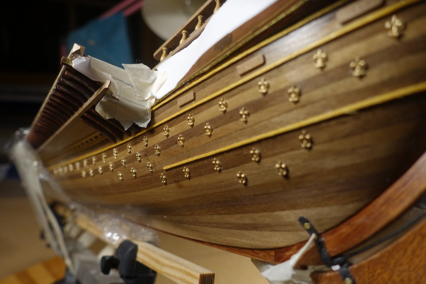
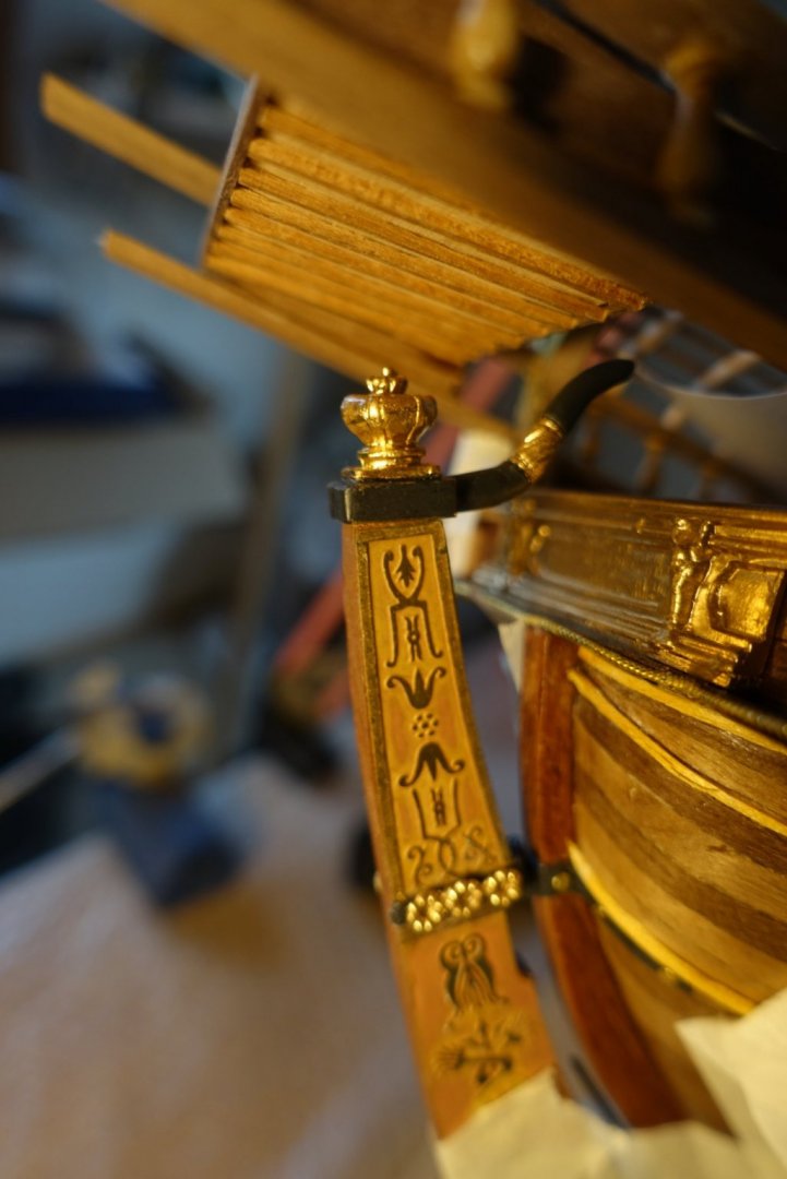
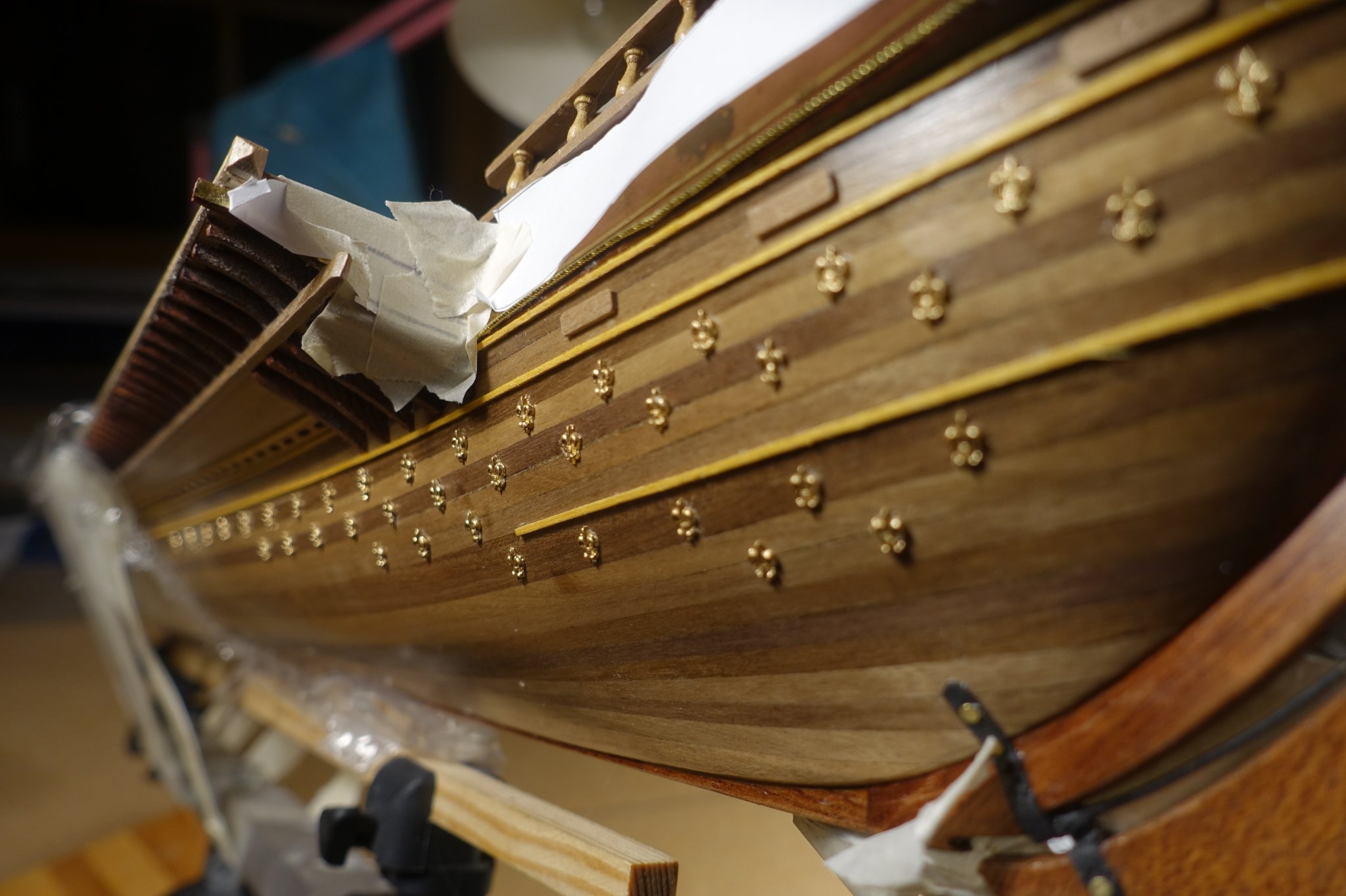
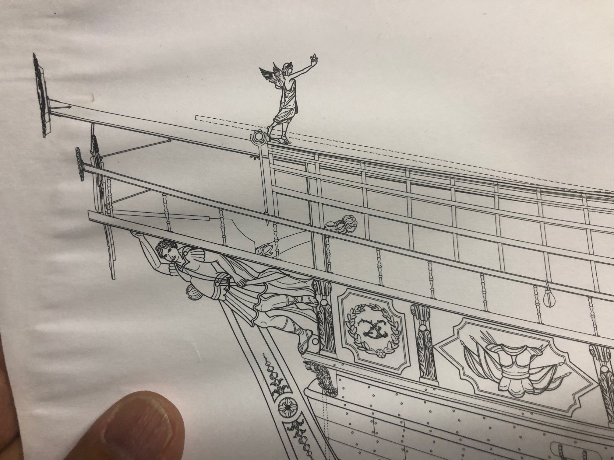
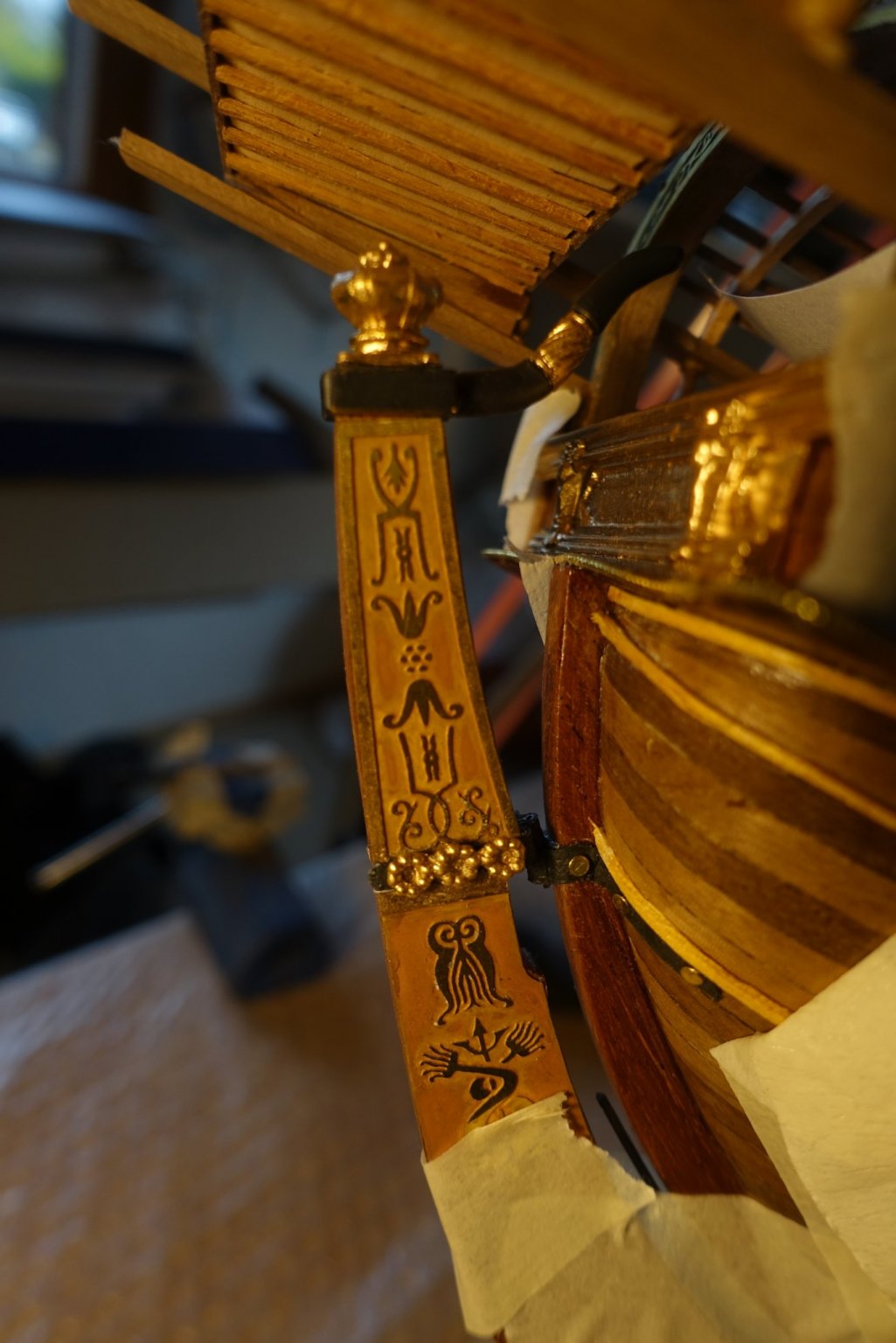
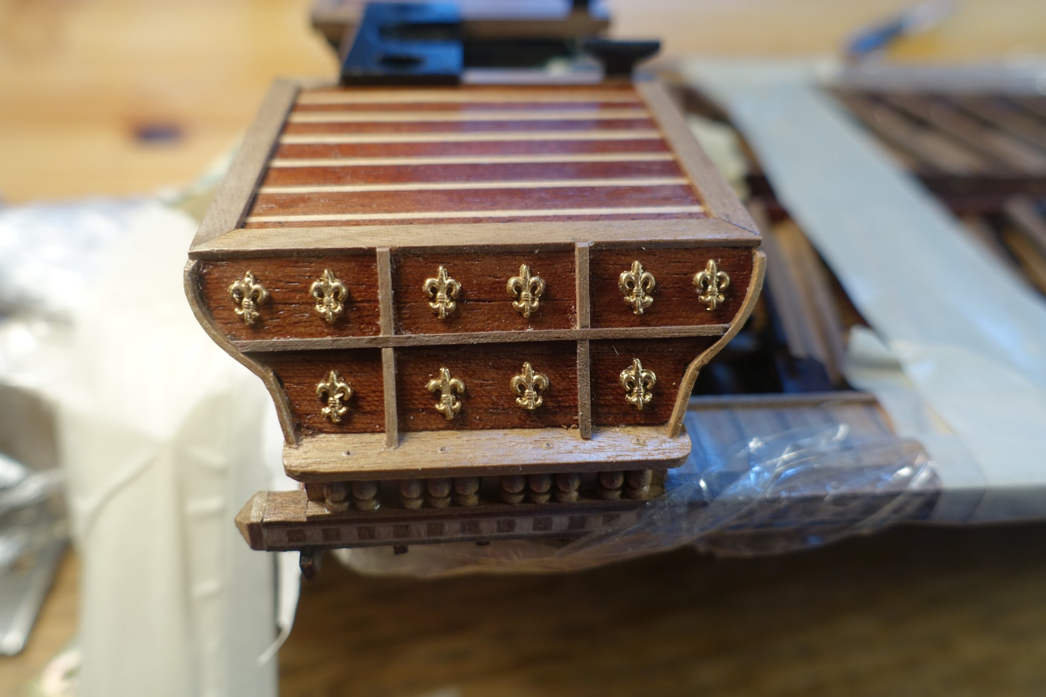
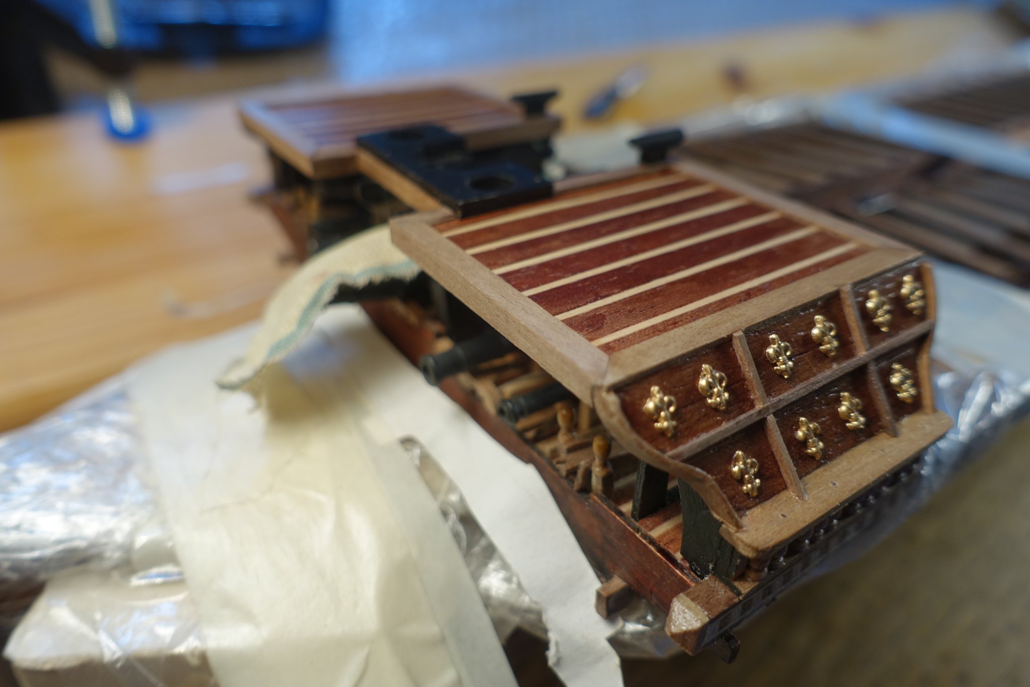
it might be overkill but follows the picture below. Morever, I thought it would be a very nice contrast to the dark wood structure of the hull. I have shortly thought of blackening the ornaments but I finally painted them gold just to get the contrast. Gimo is surely right that they were painted directly on the hull but this is far beyond my skills.
I fixed them with a gel-type CA glue. Some of the ornaments were carfully sanded on the backside to get an even surfeace to attach the glue. There is not a lot of time to correct the position. I have used several wood strips, horizontal and vertical, to mark the position. Woodstrips were cut using the ship waterline shown in the corelplan.


-
Lily ornaments were glued on the hull. When finished, there were only 3 lilies left. Thus, the further ornaments must be made in another way. I am quite sure that I did not drop any of the ornaments. But I had to sort out about 10 of them since they were not fully casted.
- fmodajr, Archi and GrandpaPhil
-
 3
3
-
17 hours ago, Gimo said:
Hi Clark,
Corel plan is correct. This is how the oars were fitted
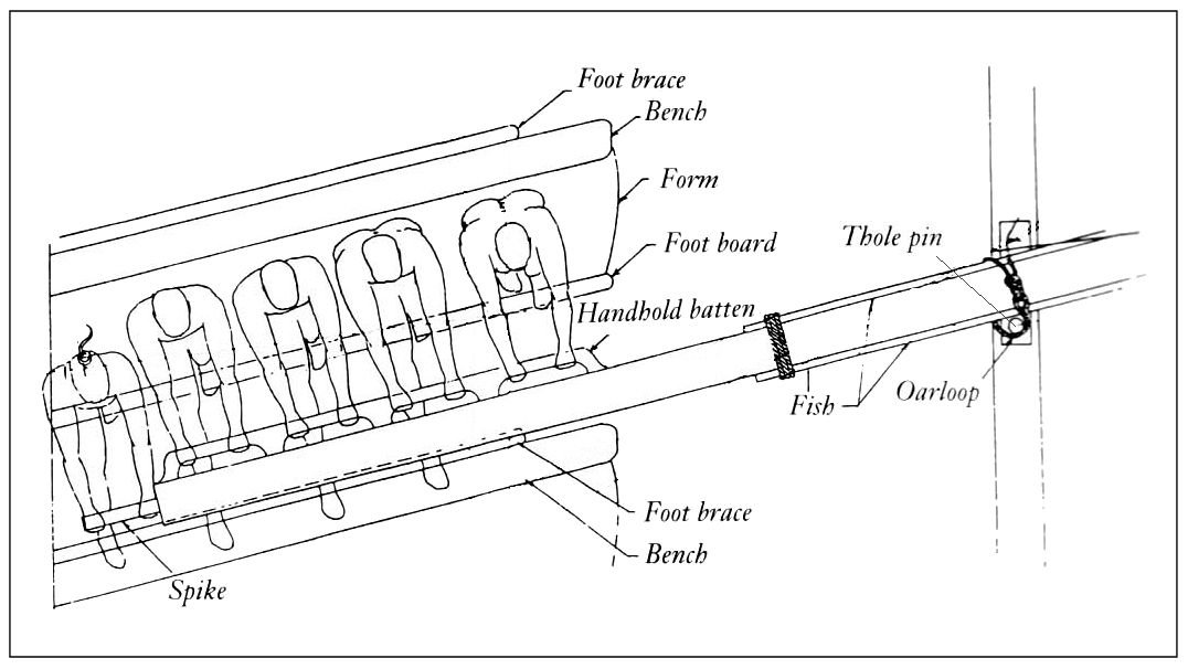
In this kind of rowing (scaloccio) the oar is a second order lever
whose fulcrum is at one end in the water and the oralock only does the point of resistence.
The force applied by the oar against the water causes the oarlock/boat to move.Gimo
Thanks a lot Gimo, it really helps me. Thus, most of the force is transferred via the oarloops. If will probably simulate an additional leather protection between pin and loop. However, this will surely be some times later. At present I was wondering where to place the oar supports.
Again thanks a lot
Clark
-
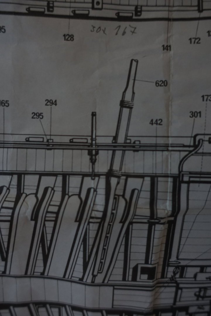
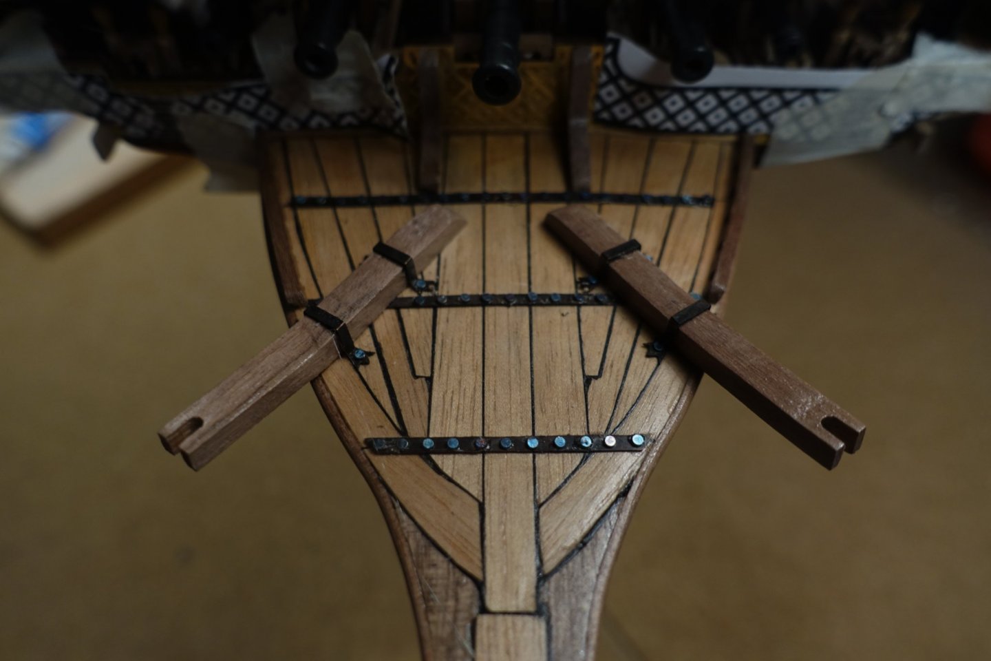
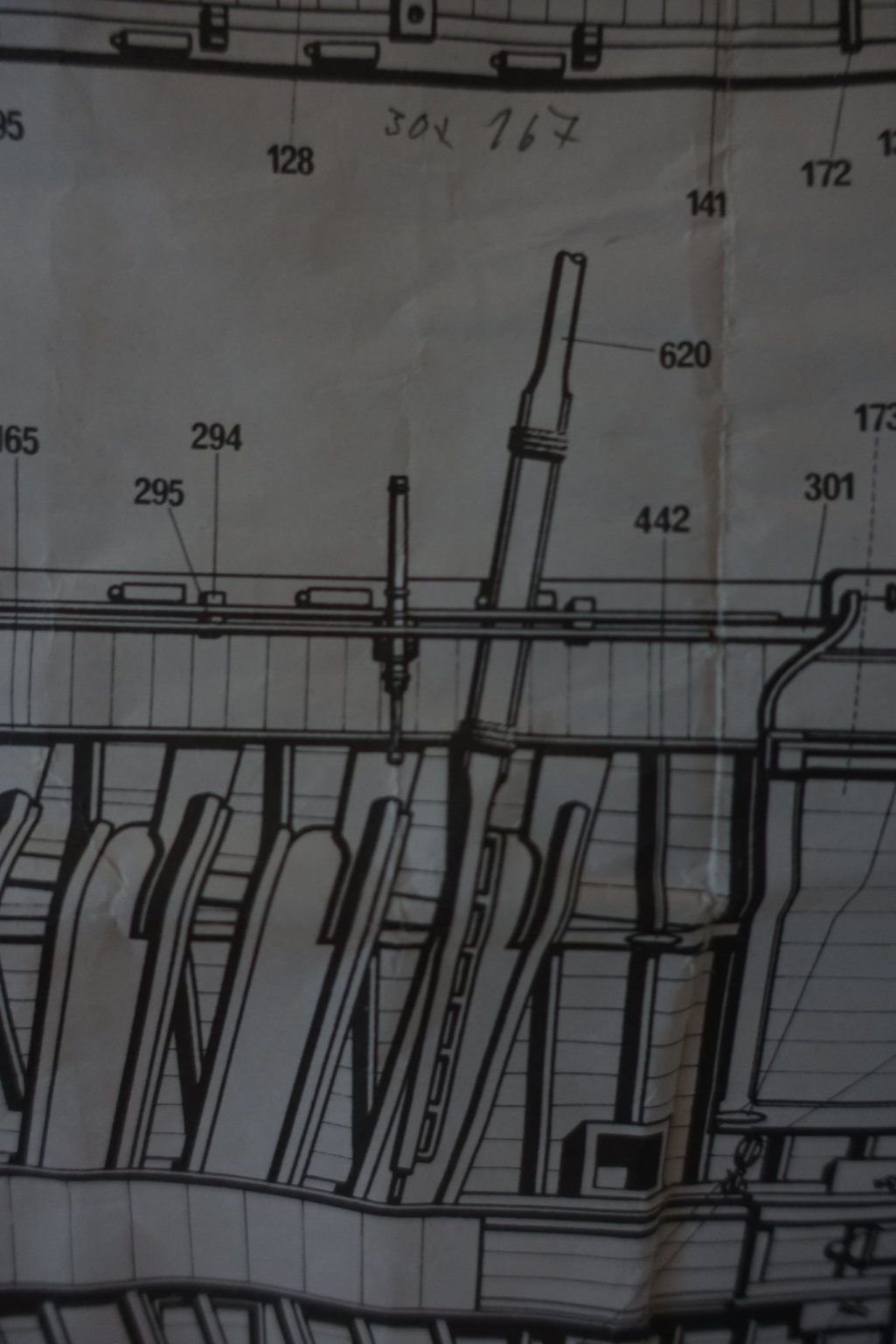
Hi Frank, just a short question. Hope you can help me. I am proceeding and started to place the oarlocks. But I was wondering about the Corel plan. It is shown that the oarlocks are on the stern side of the respective oar. I am quite convinced that they should be positioned on the bow side. Otherwise it would be impossible to transfer the force of the oarstroke onto the boat. I took a foto of the corel plan and simulated the correct (?) position of the oar in relation to the oarlock with a wood strip. I hope I could explain the problem. If yes, do you agree with me?
Clark
-
-
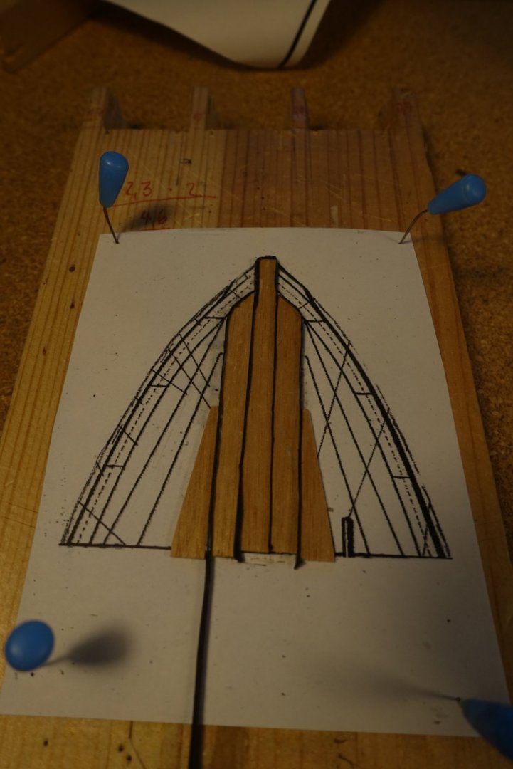
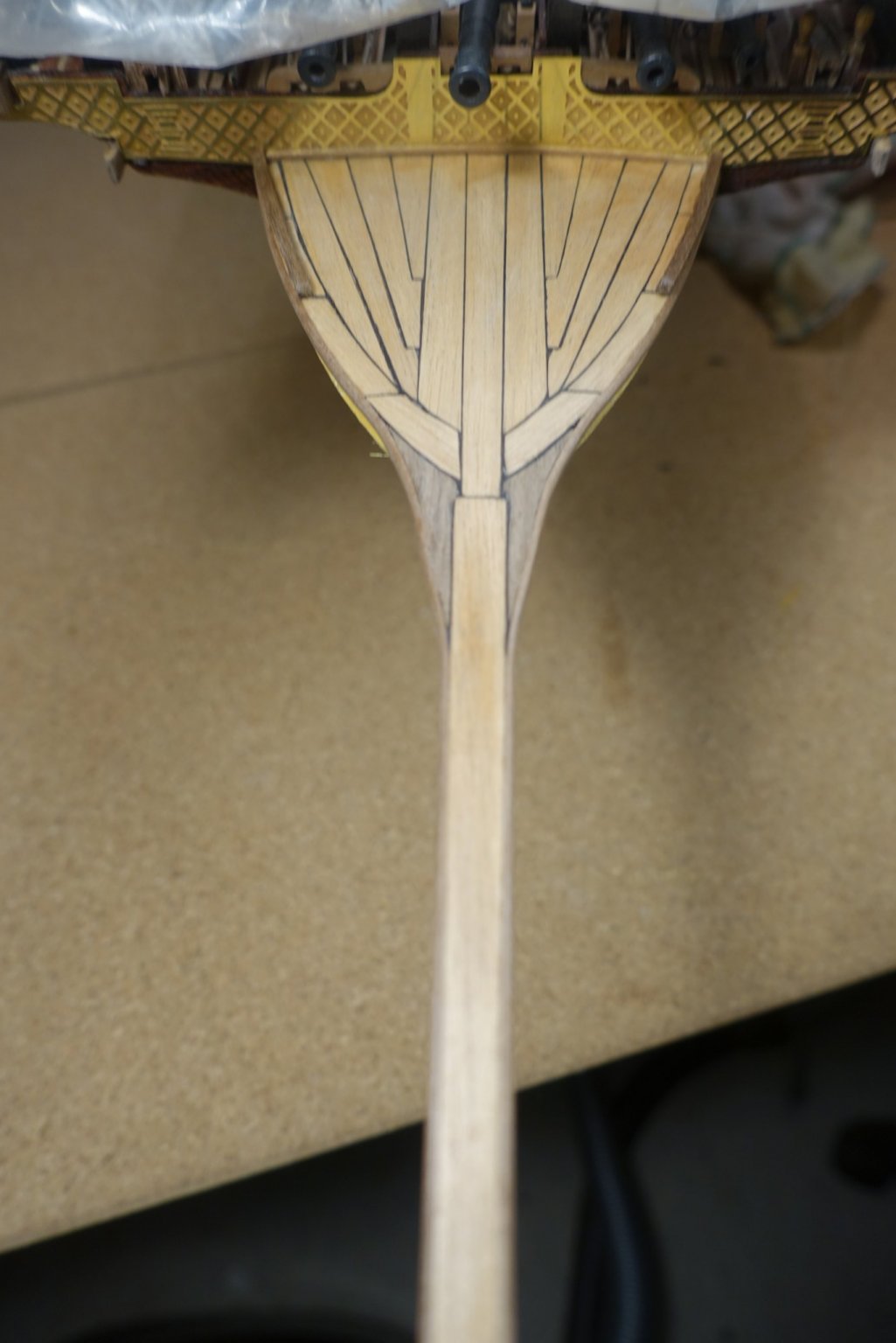
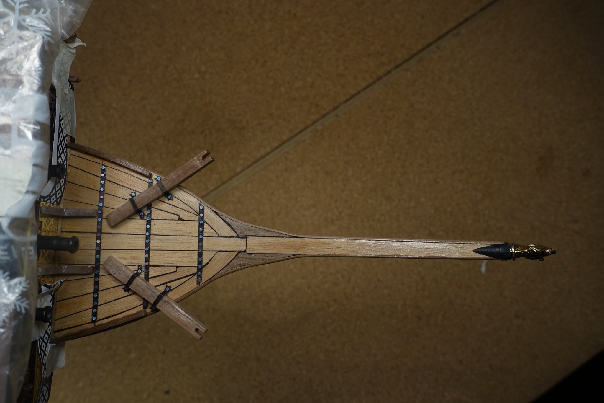
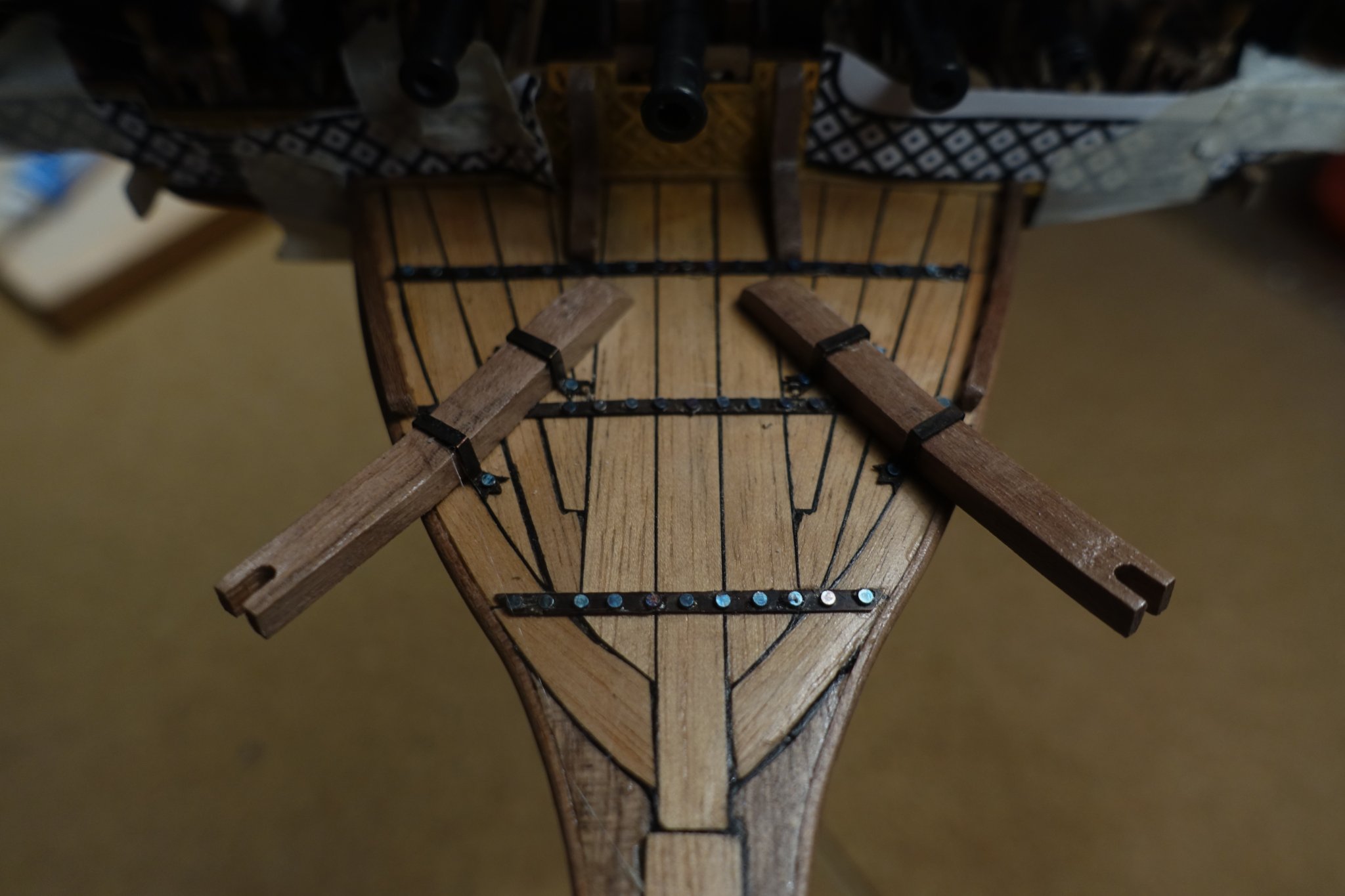
Planking of the bow area follows a certain pattern. After tracing the plank outline onto wood strips, planks were cut and glued onto paper. To simulate caulking, I used small strips of paper glued between the planks. Paper strips were cut when planks were glued.
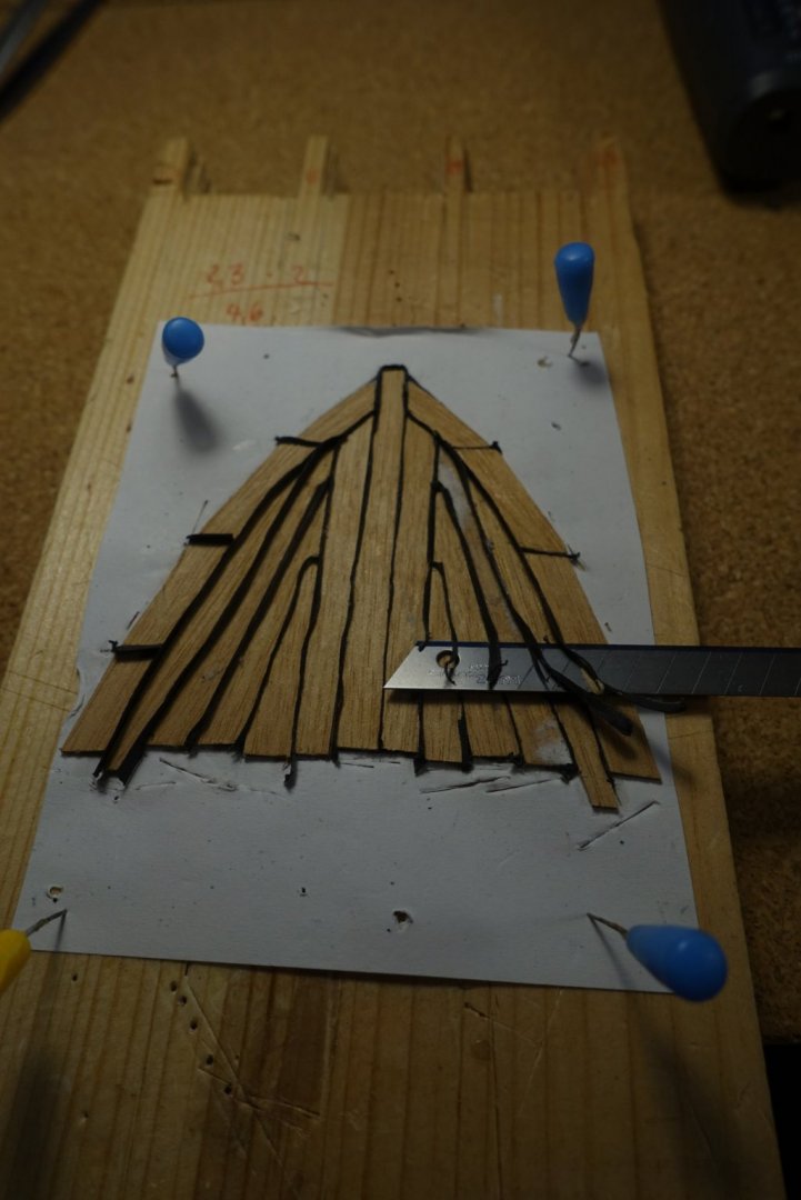
Planks were then sanded and glued on deck as a whole block. Knees, edges and rails were glued after sanding and smoothing the contour.

Cathead material provided by Corel was slovenly prepared. Size differs (I noticed that after cutting the slots for the achor rope). At this point I was wondering if Corel really put enough effort to provide the wood material, since it is not the first time I noticed such an inaccuracy. Catheads were made new form walnut boards.
Cathead and metal enforcement were added. Unicorn ram at the head was “stabilized” by a conical support.

- Archi, Gimo and GrandpaPhil
-
3
-
On 11/22/2020 at 4:15 AM, fmodajr said:
Oops,
I'm having a bad week!
Just noticed the view on the port side, I put the wood figurine upside down!
Yikes!
I think I need a break from ship modeling this week!
Frank
P.S. I was able to get the wood carving off the port side without breaking it. I will reattach right side up tomorrow!
Figurine looks excellent. Glad you managed the reattachment. Are you really sure you are able not to look at the ship for one week?
Clark
-
-
On 11/16/2020 at 10:36 PM, fmodajr said:
Hi Michael,
I just received the pieces of Mica in the mail.
When I finish the area of the model I am working on and do some repairs spotted by Gimo, I will see if I can make some use of the Mica.
I am trying to think of a way to attach the window opening pattern copied from the plans onto the Mica and then grinding to shape. If I can find some glue that will come off the Mica when I'm done shaping, I think it might work!
Thanks
Frank
Hi Frank,
Most of the glue types will probably ve visible under the Mica. Do you have ever tried acrylic glue to be hardended by UV light which is very transparent at least to my experince. I do not know if it works with Mica and wood.
Clark
-
21 hours ago, fmodajr said:
Thanks for the photo Clark!
Looks nice.
Strange that the rudder tiller seems to go into the Royal seating area.
Did the king steer the boat? Lol! Joking!
I'll try to be more careful with the sheet metal. thanks for bringing the issue up .
Frank
I was also wondering about the handling of the rudder tiller. Not only because it stretches into the kings area but also because it is very short. I would assume that there is a huge horizontal energy with the waves wich would it make very difficult to handle such a short tiller. Maybe there were additional blocks and ropes used to enhance the leverage. Is there anything outlined in the plans of Fleur de Lis about the rudder?
Clark
-
6 hours ago, fmodajr said:
Hi Clark,
Yes, the sheet metal is real flimsy!
Do you have any photos of the upper part of the rudder assembly?
I will have to start working on that soon.
thanks,
Frank
Thanks, Frank, for accompanying me. Maybe I made the mistake that I left the brass pieces too long in the blackening solution. They broke immediately when I tried to adapt them finally to the rudder. They were preadapted before putting them in the blackening solution.
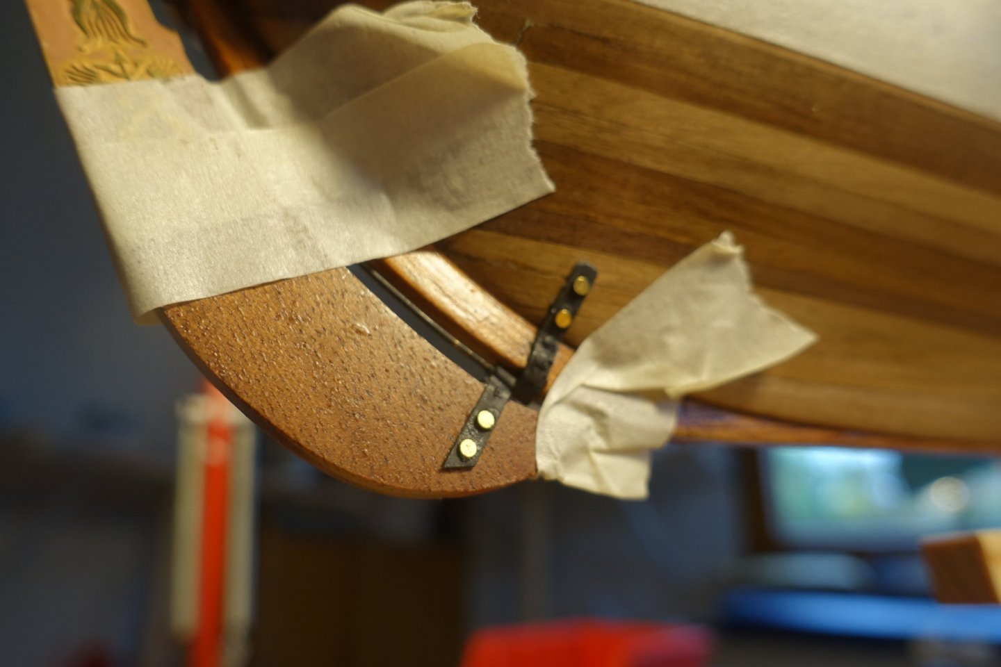
Although the upper hinge seemed to resist the blackening solution, I replaced it also by card strips to get a uniform appearance (photo below).
It may be better to paint the hinges with email paint and not to use blackening solution.

- Archi, fmodajr and GrandpaPhil
-
3
-
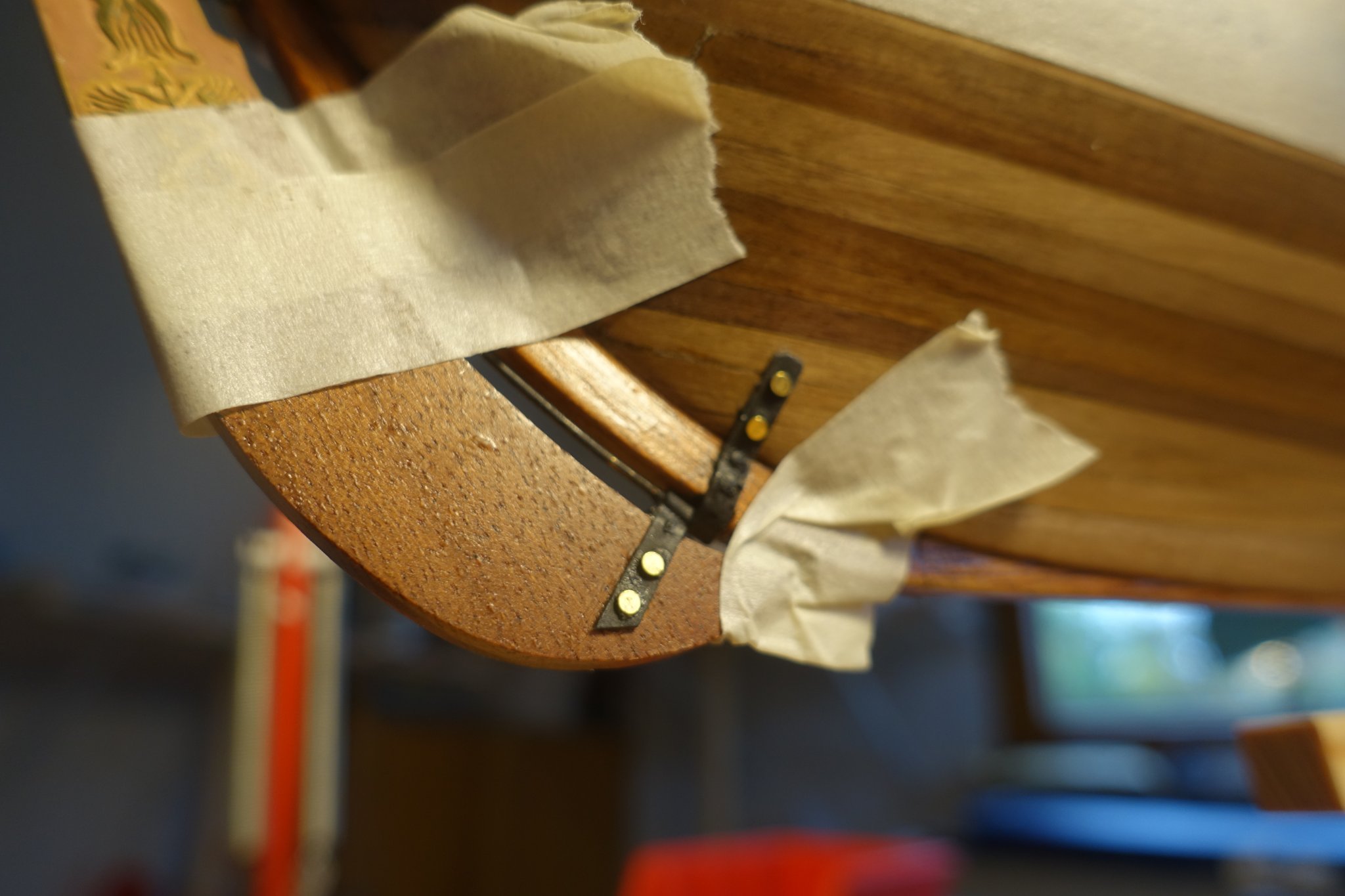
The brass pieces provided for the rudder hinges did not resist bending and blackening at least the way I did. Thus I replaced them by card strips.
Stern part is now ready and I will proceed with the bow area.
- ccoyle, fmodajr and GrandpaPhil
-
3
-
14 minutes ago, fmodajr said:
Looks good Clark!
Glad the flexible wood worked out for you! Wish me luck! Lol!
Frank
It really took some efforts to get the bending. Your way may be better. Luck and patience.
Clark
-
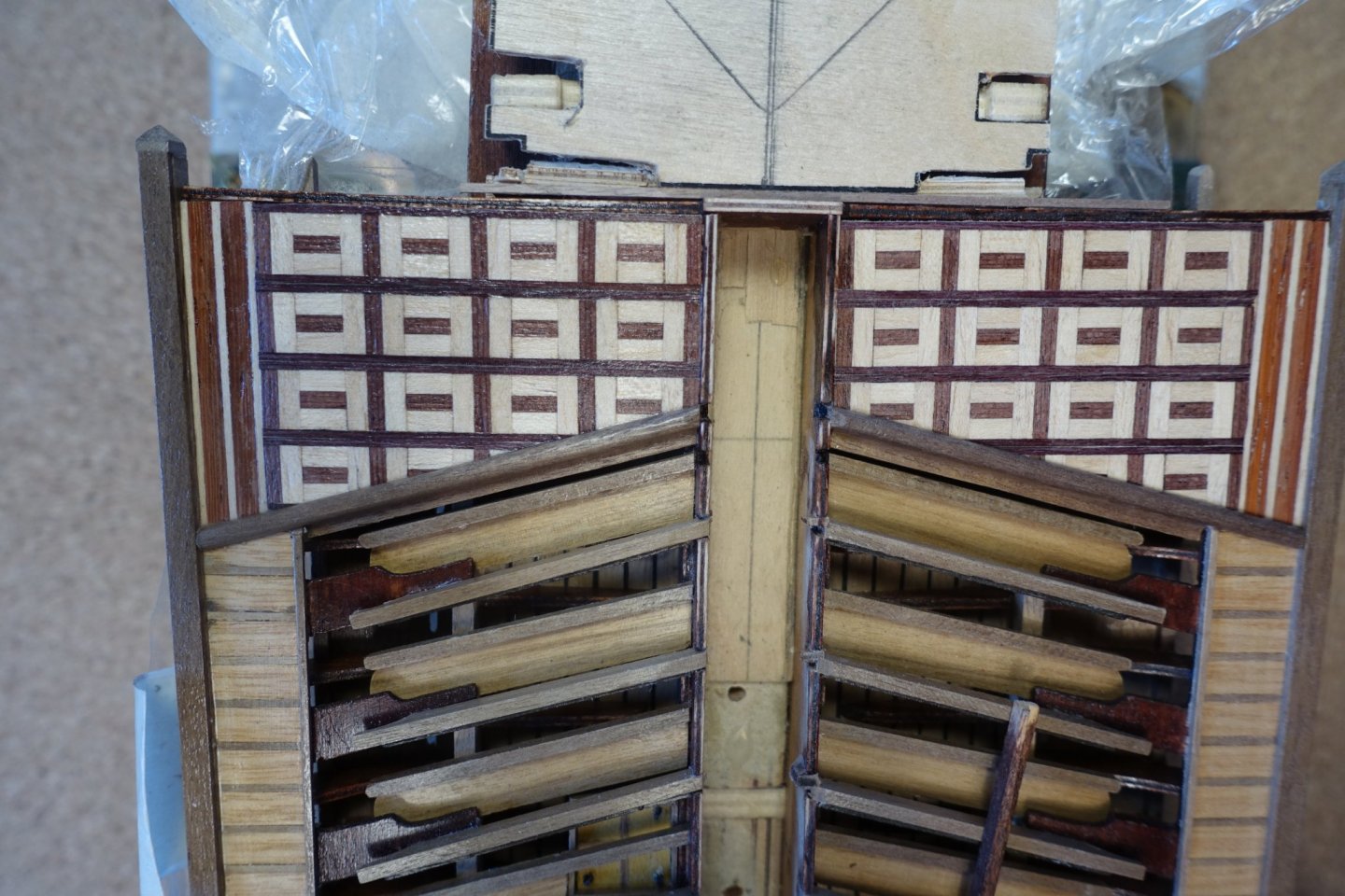
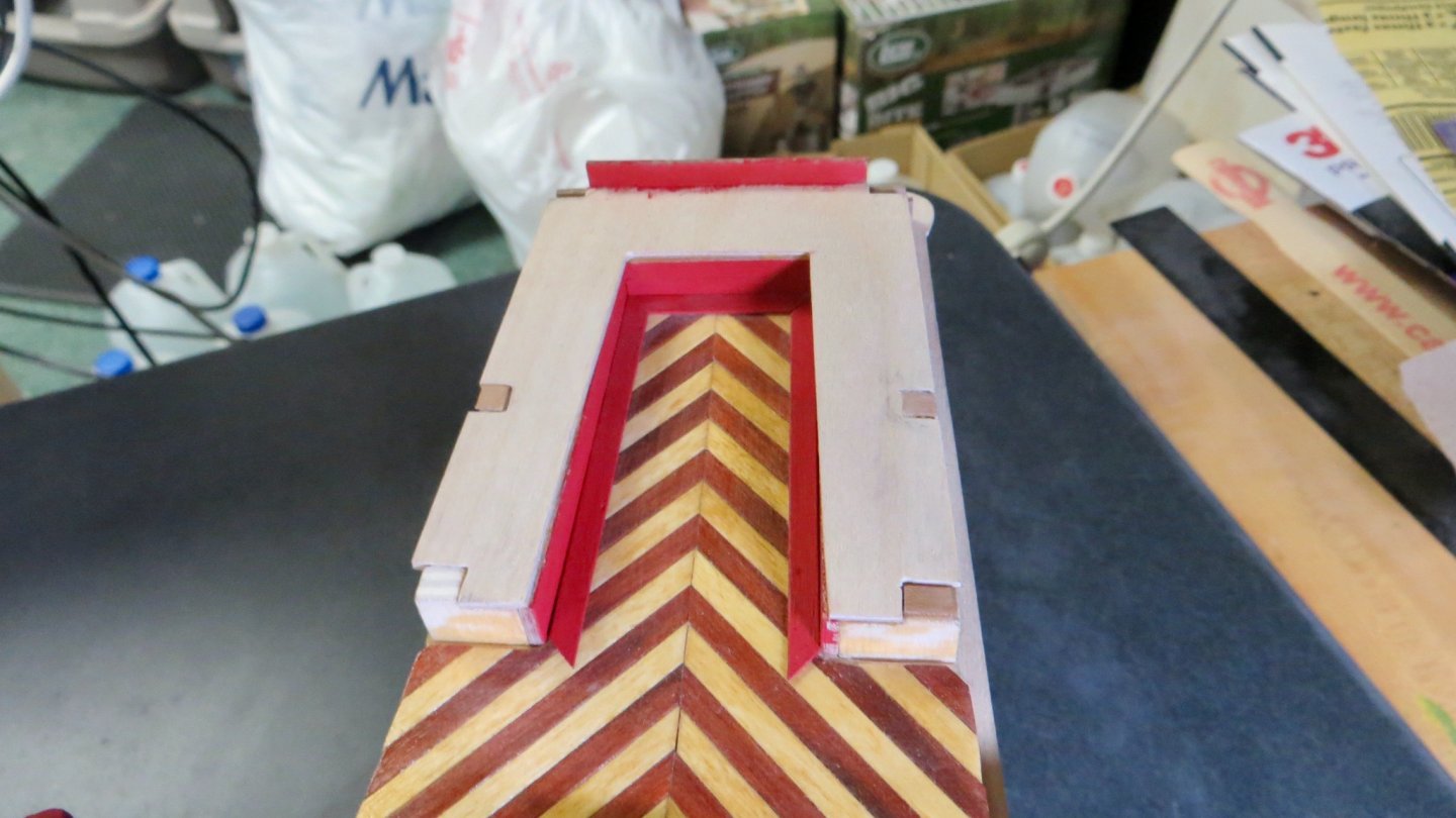
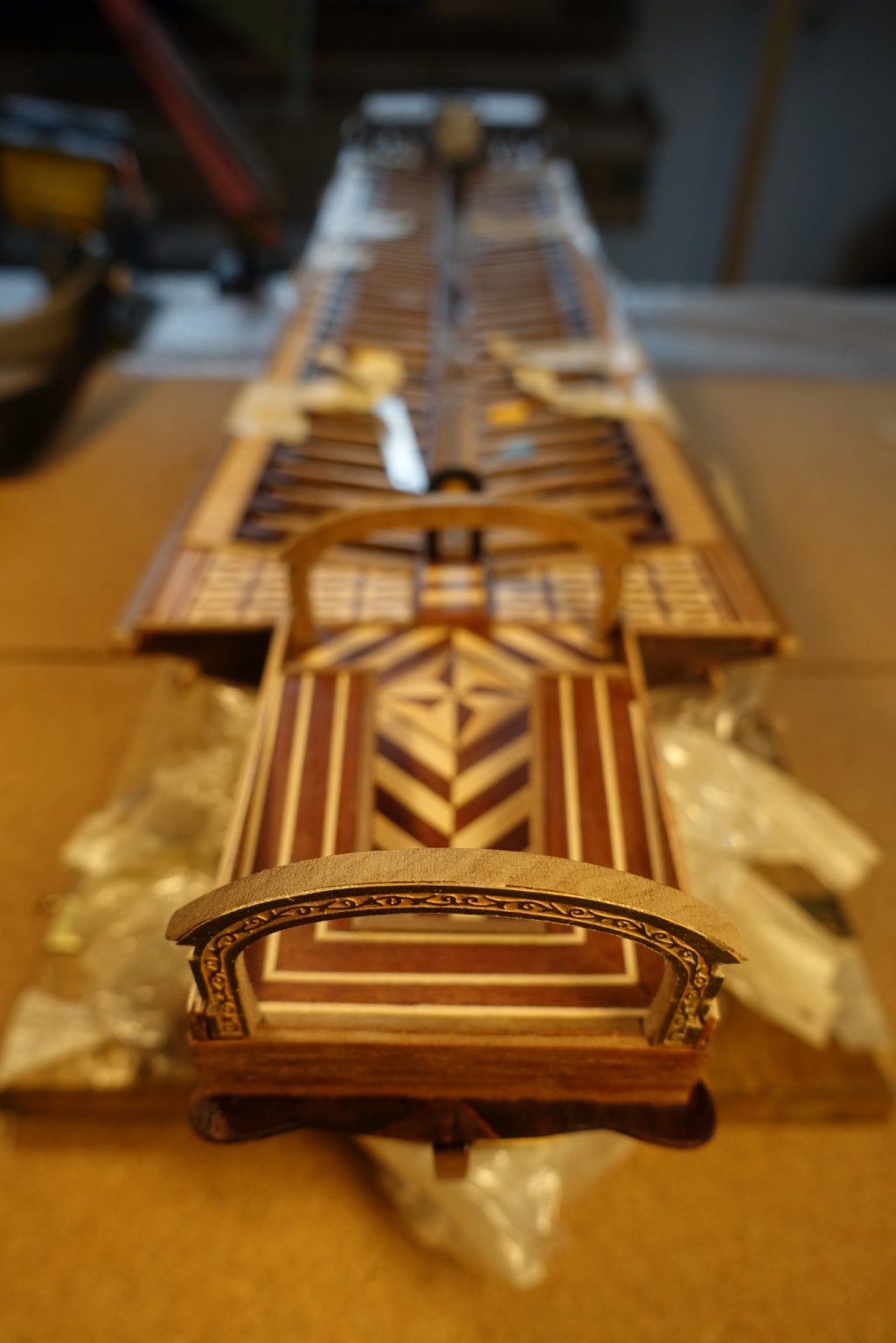
For adapting the arches covering the kings platform, I used and sanded the template provided by Corel before proceeding the way Corel manual suggests. This because the arches had to be put in line with the arches already glued at the stern platform. It took some time but it was the best way to fit the strips.

Railings were fixed before putting the arch construction on. According to Corel there should be a window line between the railings: So far none of the Reale builders (fmodajr, bender, gimo) liked it. Me neither. I replaced it by some pillars.

- Gimo, GrandpaPhil and fmodajr
-
3
-
9 hours ago, fmodajr said:
Hello,
Thanks Clark and everyone else for stopping by!
Began work on another platform situated behind the Royal seating area.
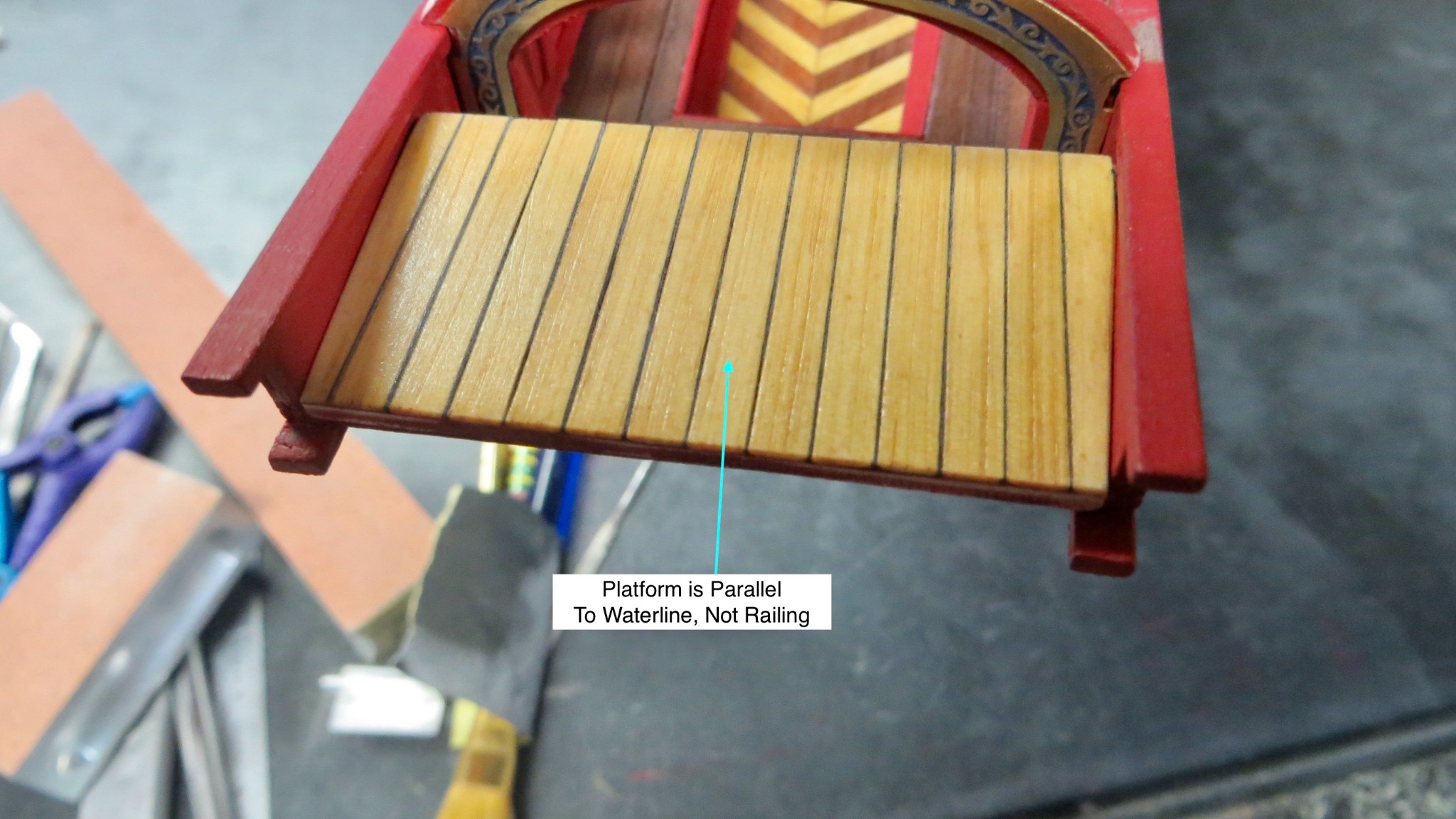
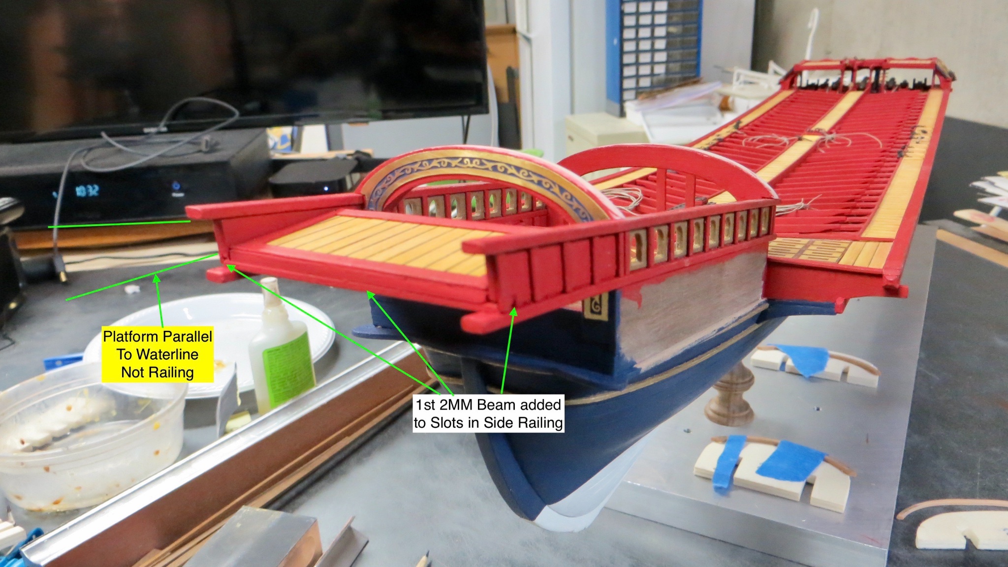
This platform does not follow the slope of the railings. It sits parallel to the water line.
The Corel kit seems to indicate that the modeler just glue the edges to the inside of the window panels on both sides. I wanted to make the platform sit more securely (It will hold a large Flag pole and flag).
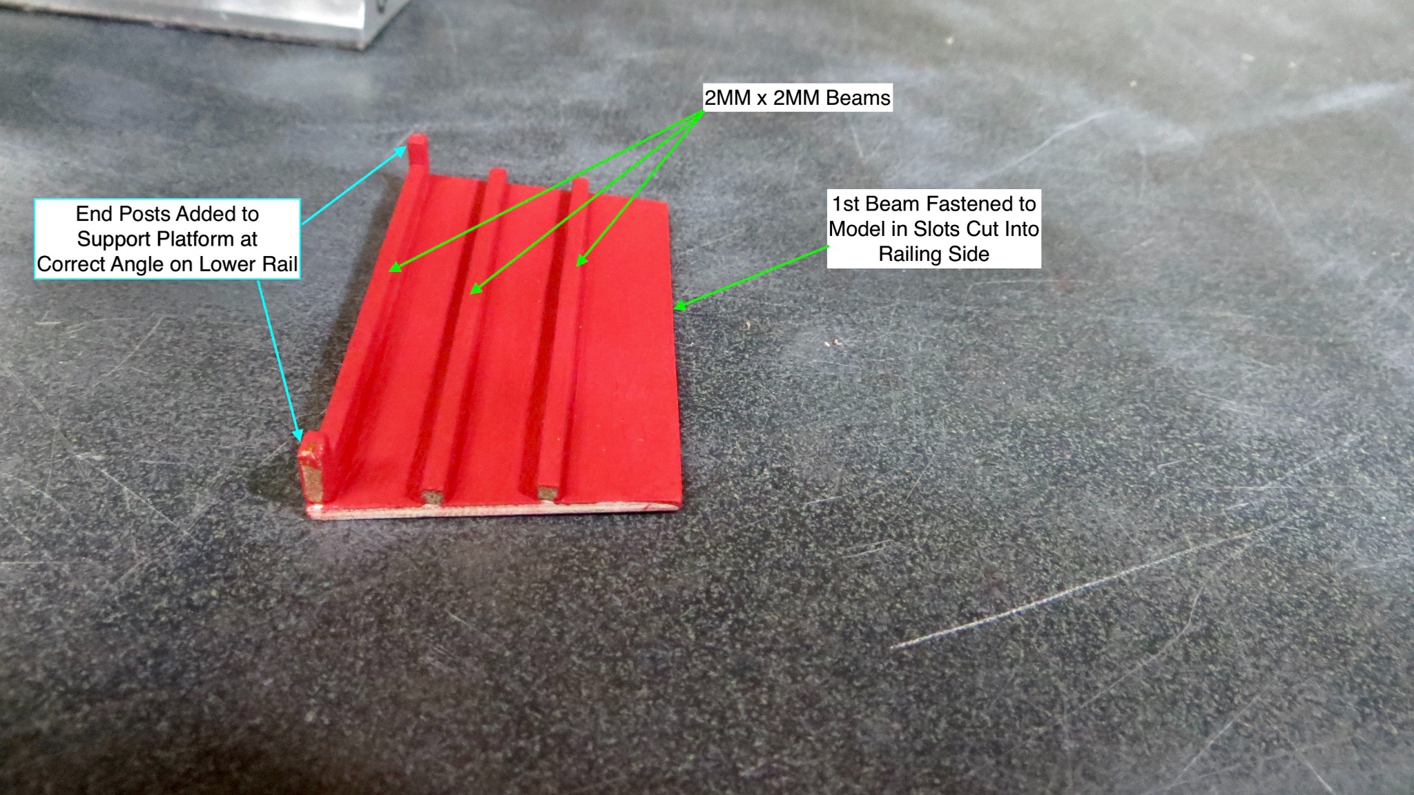
The plans call for 4 beams (2mm x 2mm) on the underside of the platform. I left the first one off and glued it to the side panels (as you will see in a bit) and 2 legs were added at each end of the front of the platform. These 2 legs will sit on the inside of the lower railings, allowing the platform to be at the correct angle with more support to the structure.
Underside:

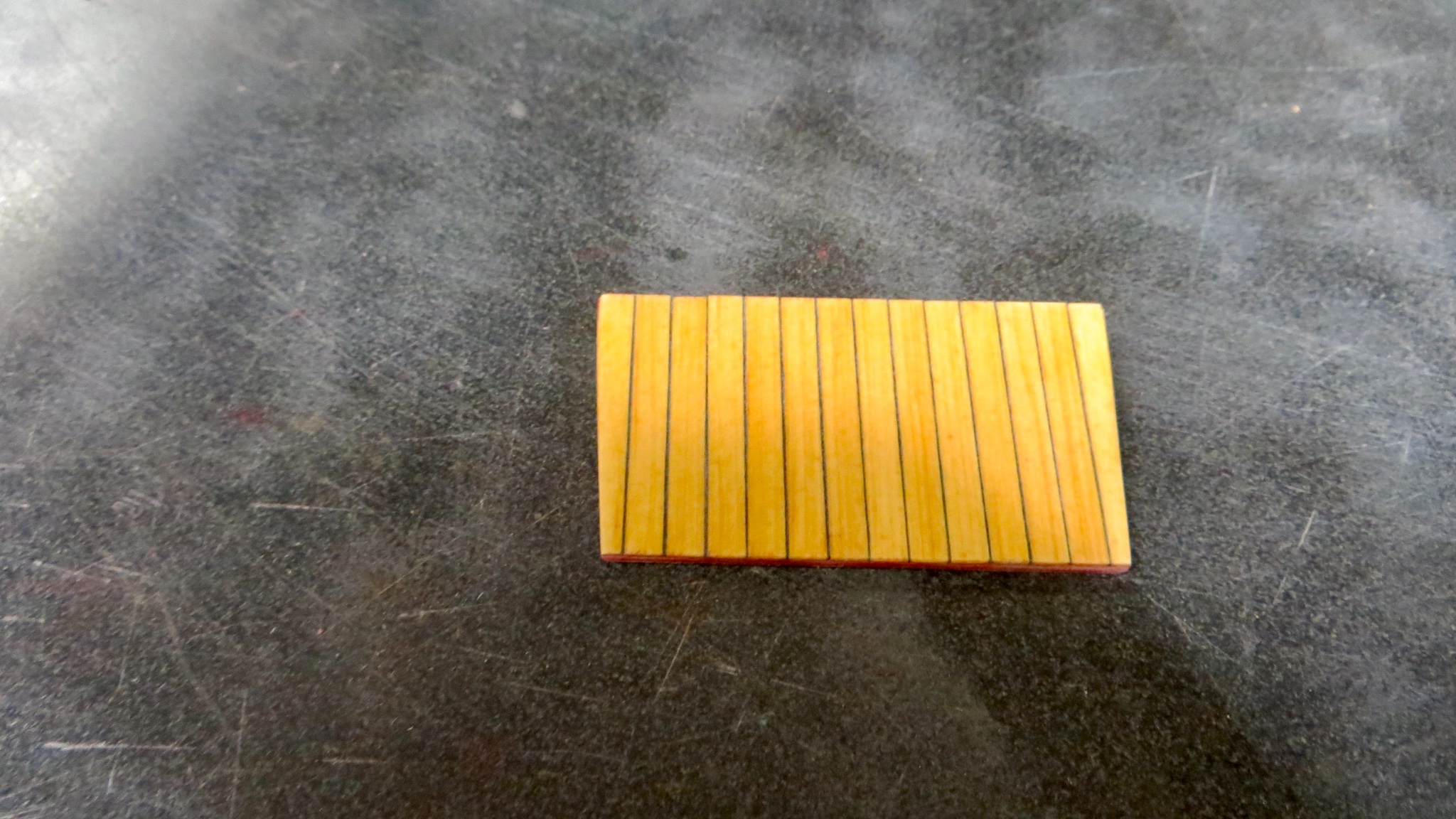
I had to decide on what type of deck planking to put on this platform. Since I am guessing any member of royalty or person of importance would not be on this platform, It was decided to plank using the same Eastern White Pine, stained with a light oak finish. (Same as the other areas of the model).
Finished Planks:

Installed platform between the two side panels with legs sitting on the inside of the lower rails.

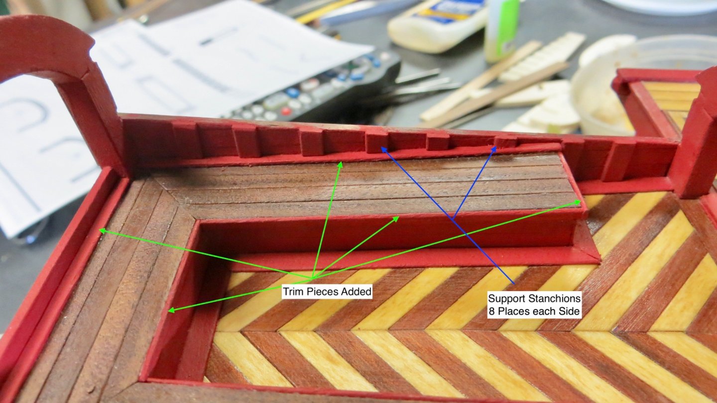
The next photo shows the platform viewed from above. Trim has been added. The plans also call for a 2mm round bar to be attached to the inside of the side panels. Not quite sure yet what this bar is for, so I decided to play it safe (In case it supports some rigging etc) and drilled thru both sides of the side panels, finally sliding the bar thru in order to give it more support.
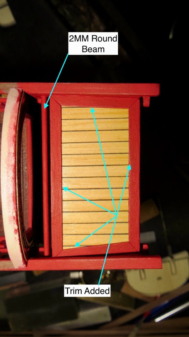
View of finished platform.
The angle of the platform can be seen along with the first underneath beam attached to the slots in the side panels.

Now I have to start working on what I view as the most difficult part of the model: the canopy arches.
Yikes!
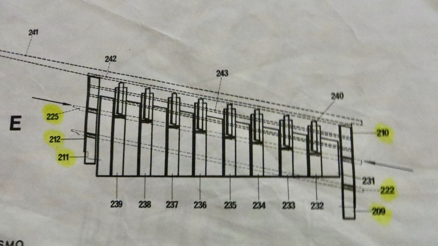
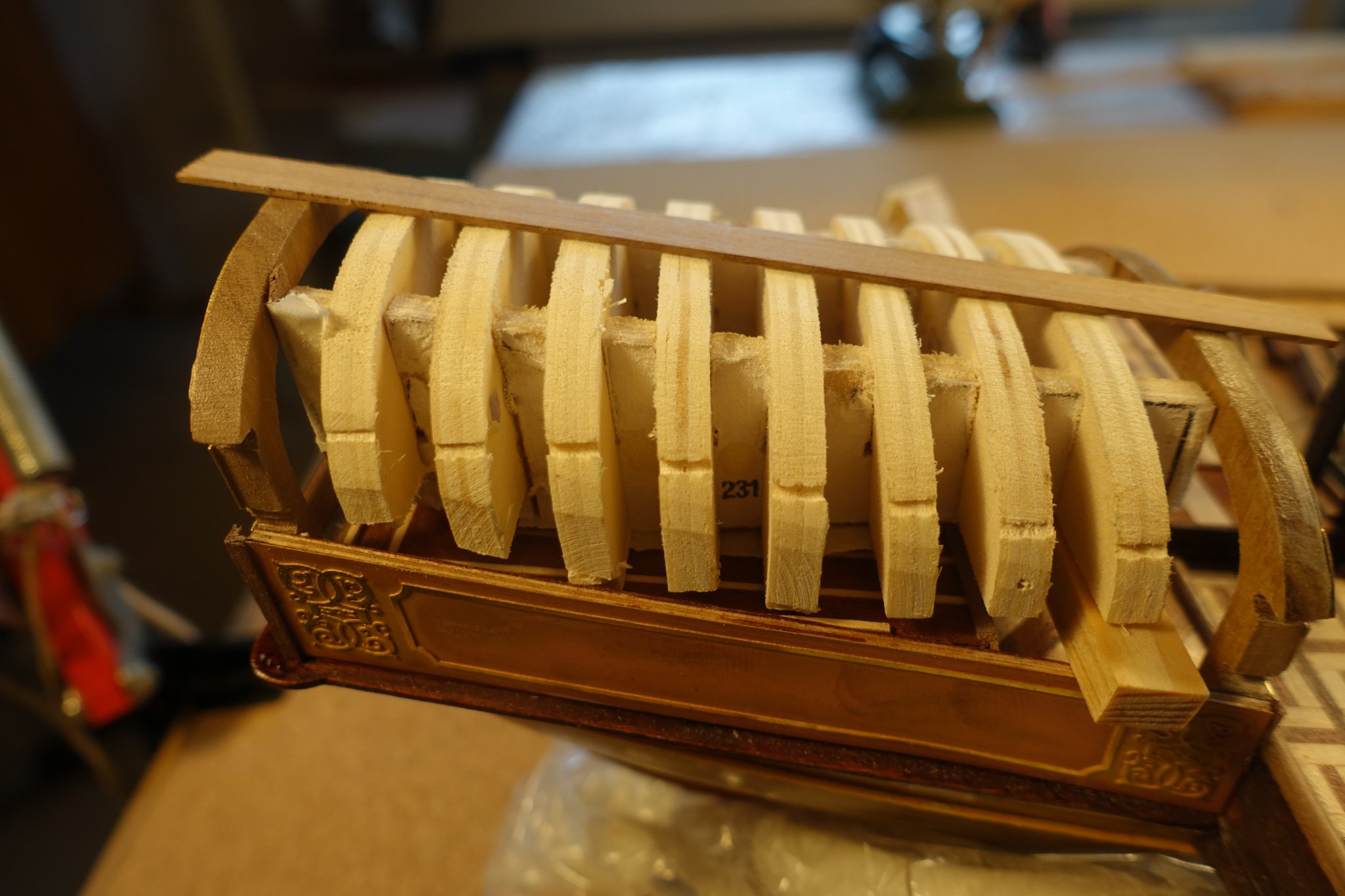
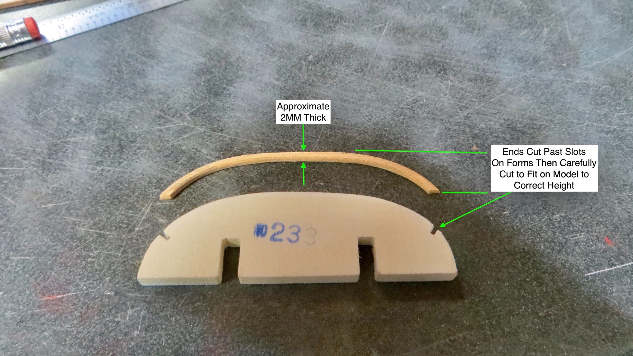
The plans call for (see next photo) 8 wooden forms (nos. 232 - 239) to be fitted onto 2 pieces (nos. 231) and sit inside the seating area. Then I am supposed to use 2mm x 2mm flexible wood and bend the arches around the frames and attach them to the ship. Once they are in place, I am supposed to dismantle the forms underneath and remove.
I am not a fan of this method, because I am not crazy about leaving wood in a stressed state.
So, I will spend some time and try a different way. Not sure yet if I'll be successful!
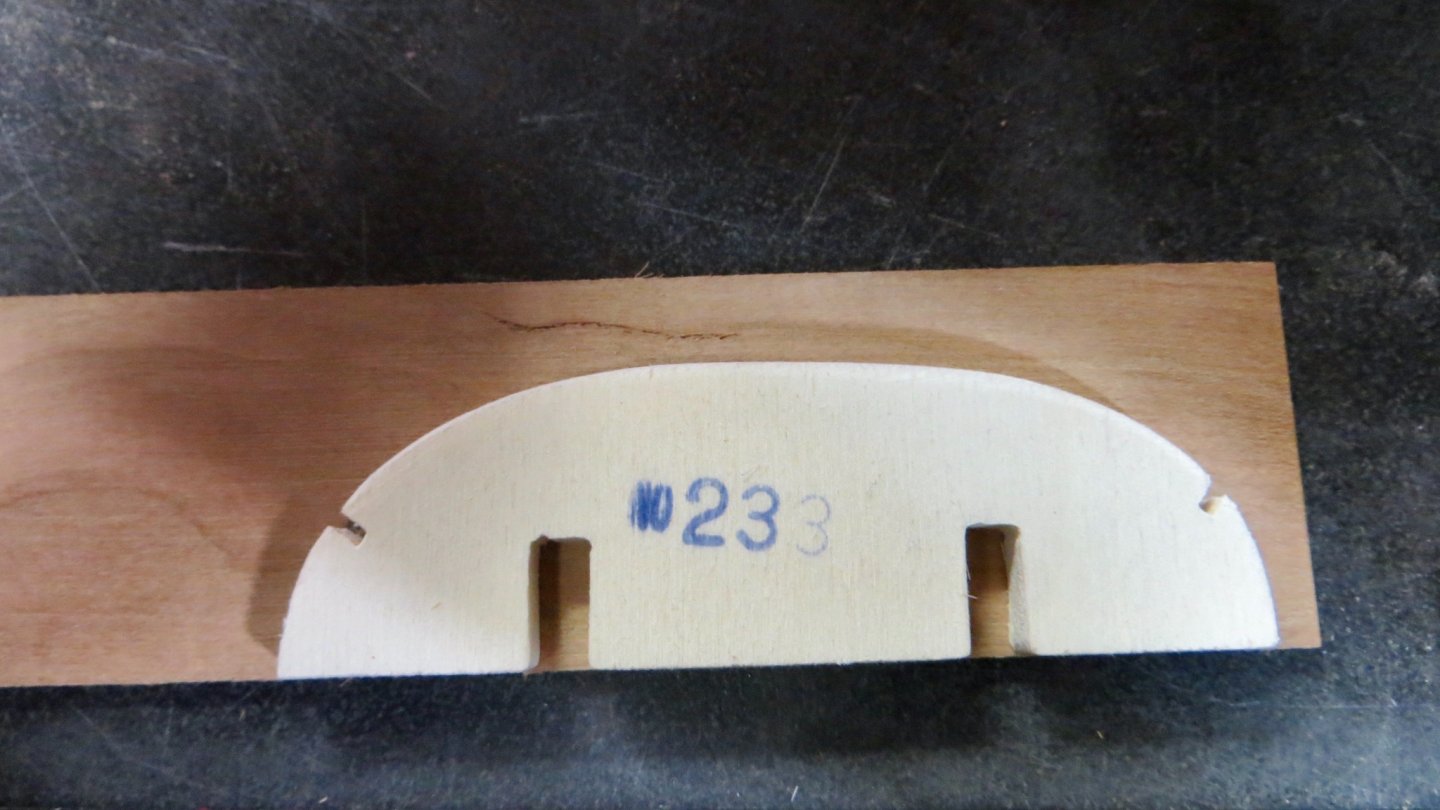
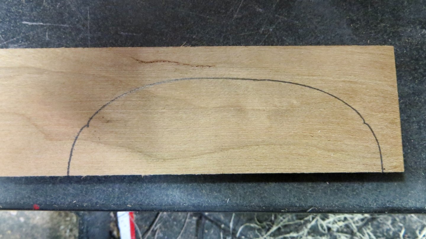
First step is to trace the form on a ground 2mm piece of wood. Using a hard wood (cherry) for this.
Using the scroll saw and oscillating grinder, the inside of the contour was finished.
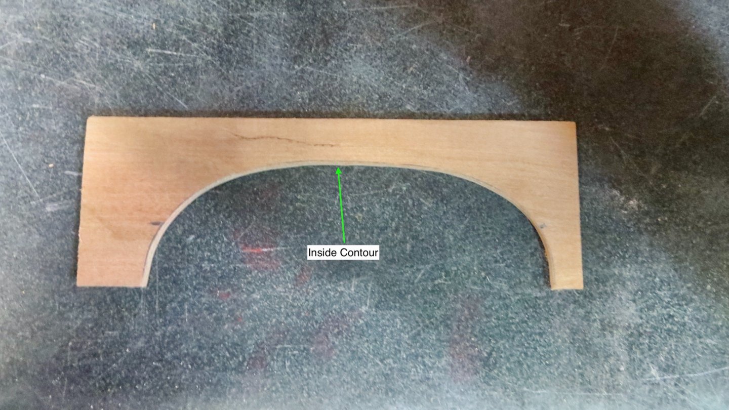
Then the outside was ground so the contour was 2mm thick. I cut each end past the marks indicated on the wood form and then kept dry fitting on the model and kept cutting back until I obtained the correct height and angle.

Completed 4 of the 8 arches so far.
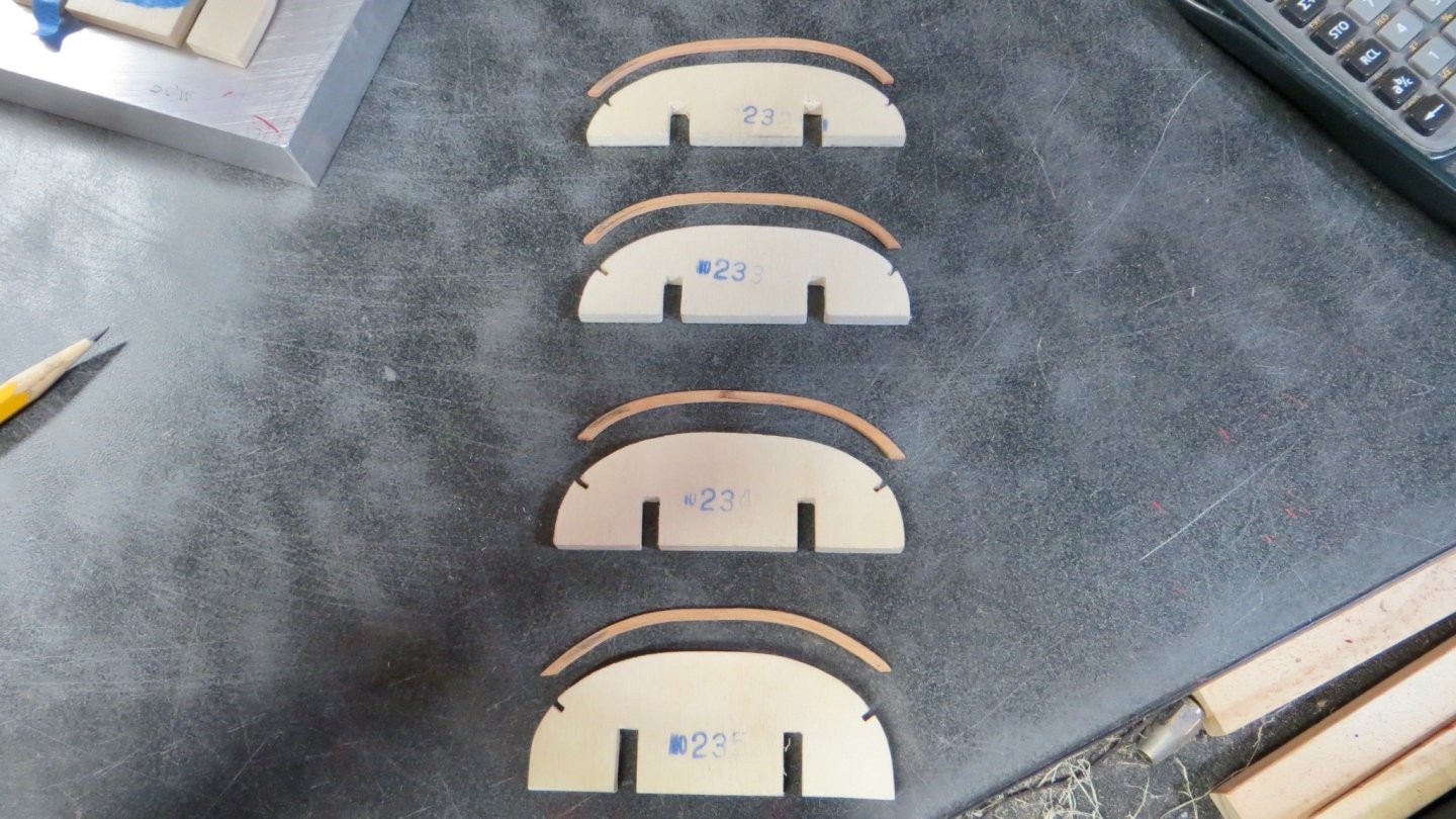
Still have a ways to go in order for me to see if this will work. At least the arches have no natural stress in them and they should stay in position once fastened to the upper railings.
Sorry for the long posting!
Frank
Hi Frank,
I am almost at the same point you are now. When building the Xebec, I had the same problem but used the flexible wood and it worked, althought it took a lot of efforts to bend the ends. Nevertheless, stressing of wood was no problem. Thus I will probably rely on the the flexible ones. For that purpose, I checked the templates of Reale Corel provides (#233 and others). They are not completely in line when placed in order and have to be sanded. Did you have the same problem? I am a bit disappointed of the Corel material.
Your solution seems much better than the flexible wood.
Clark
-
On 10/31/2020 at 4:15 PM, marktiedens said:
Nice solution to the windows!
Mark
Frank, I was also wondering how to manage the problem of windows since they are visible from the outside only. Moreover, the false windows provided by Corel do not look very realistic. I do not like them. I will probable leave the space between the rails completely free.
At present we all are watching the battle in your Country which will surely have a strong impact on Europe.
Clark
-
16 hours ago, Strata said:
Stunning. I hope the floor will be easily visible on completed model.
The floor will be covered by arches but I know that is there.
Thanks for stopping by.
Clark
-
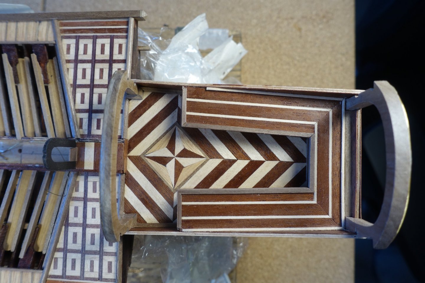
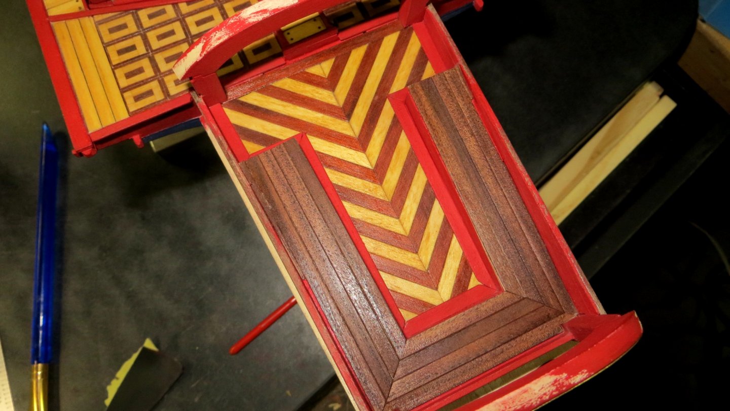
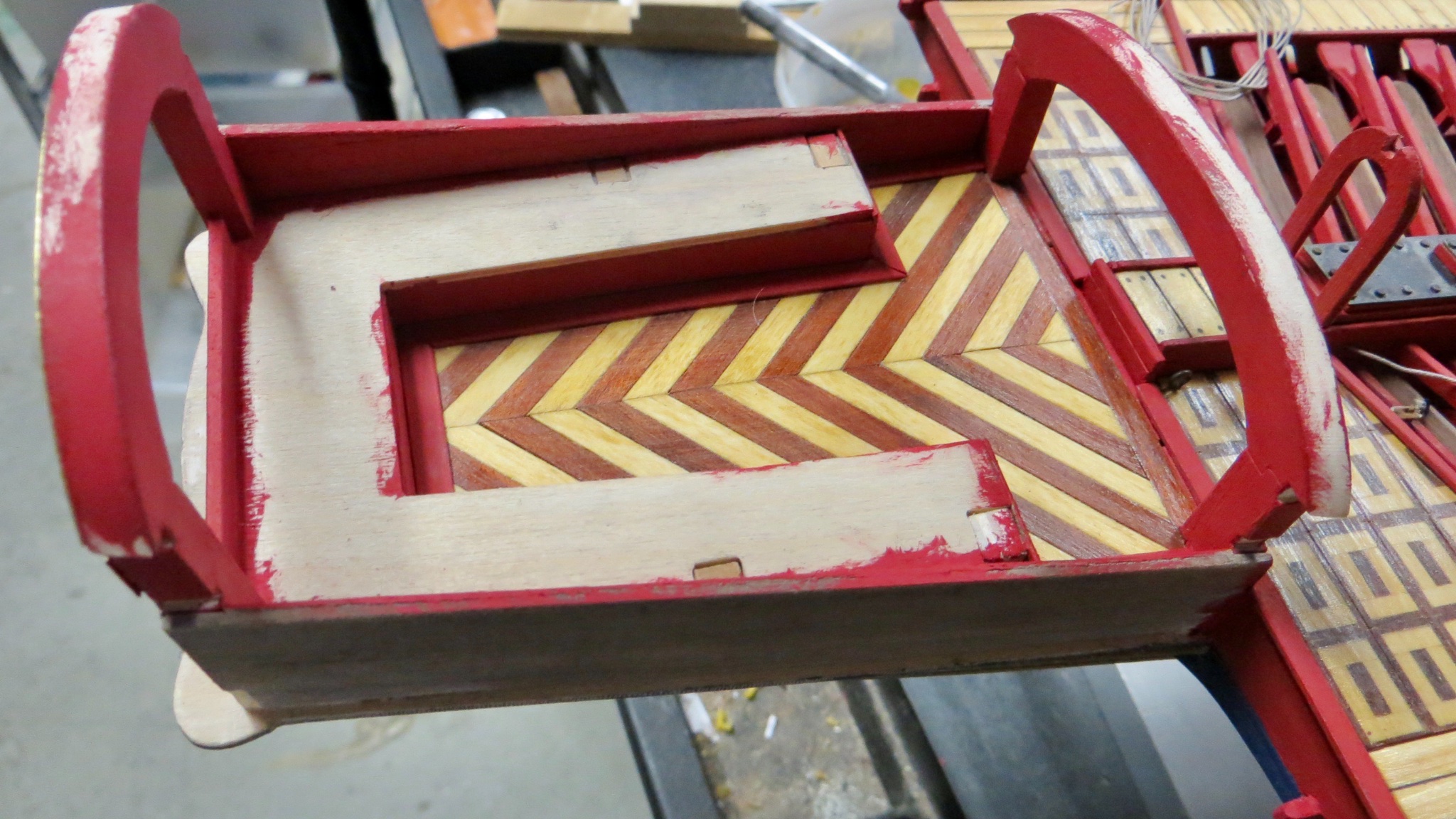
The king’s platform at the stern is ready. Compass symbol is surrounded by diagonal planking using mahogany and lime strips.

- GrandpaPhil, Danstream, Gimo and 1 other
-
4
-
For planking the decorative platforms at the stern, I used the material provided by corel. Since these platforms were the beginning of the officer’s part of the ship, I marked the “border” to the oarsmen part by a half round strip on the top and a concave one at the bow side.
Clark
- Danstream, fmodajr and GrandpaPhil
-
3
-
5 hours ago, fmodajr said:
Michael, Clark, Mark and Gimo, thanks all for the Likes on my last post!!
I was able to continue working on the stern construction.
I have been concentrating on the interior of the canopy area.
The false deck for the seating (chest) area is now installed and ready for planking.
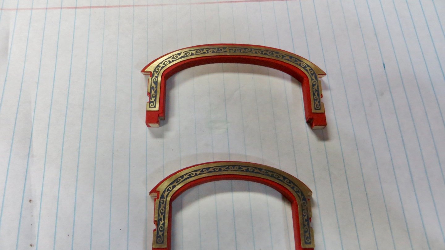
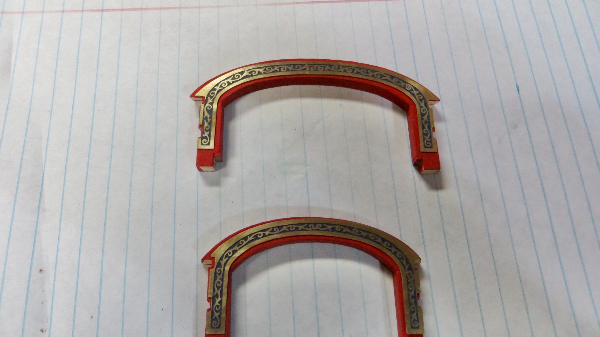
I finished the arches, then painted and attached the decorative brass.
The tops of the arches are left unpainted so I can sand the correct angle after installation.
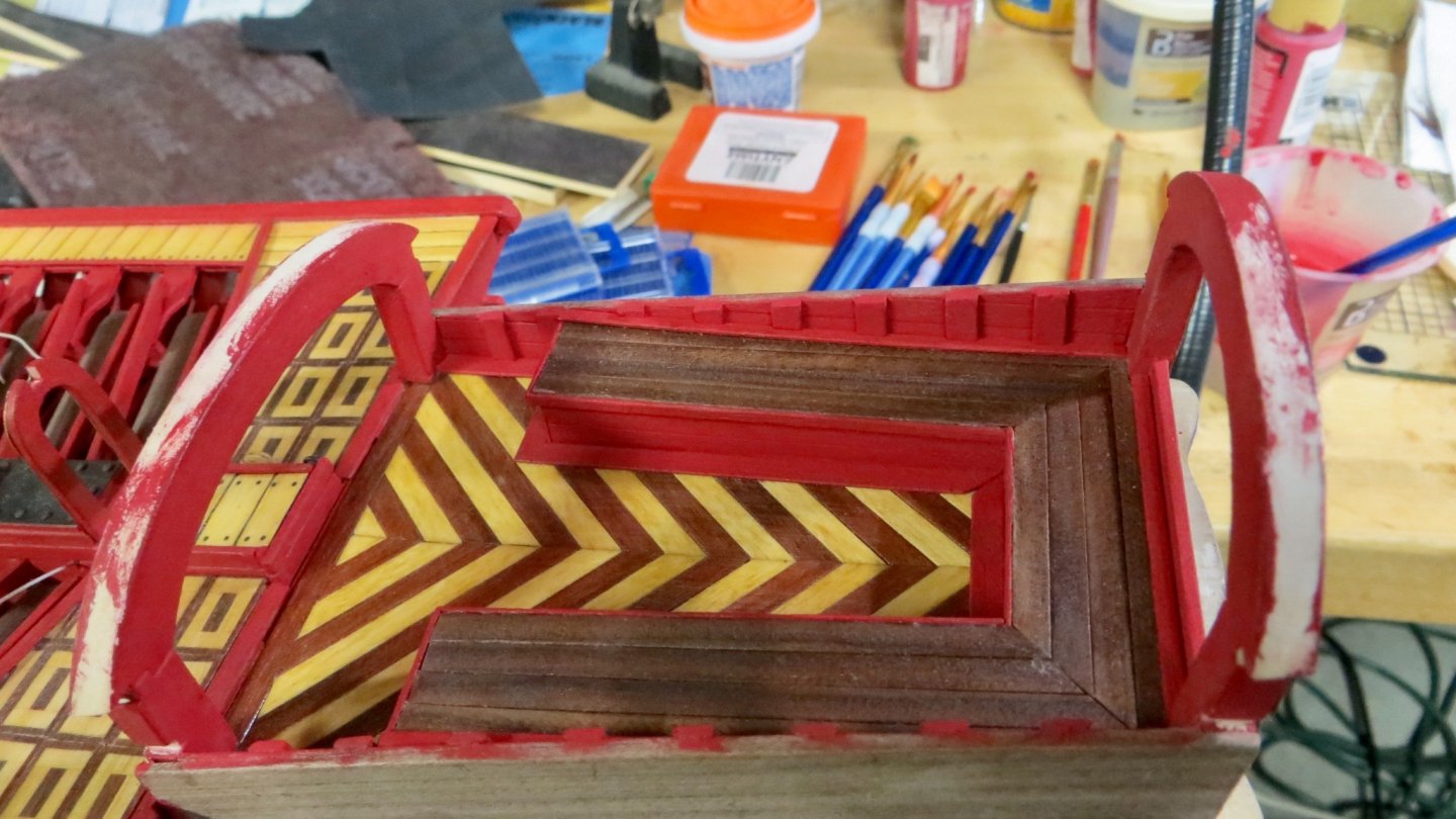
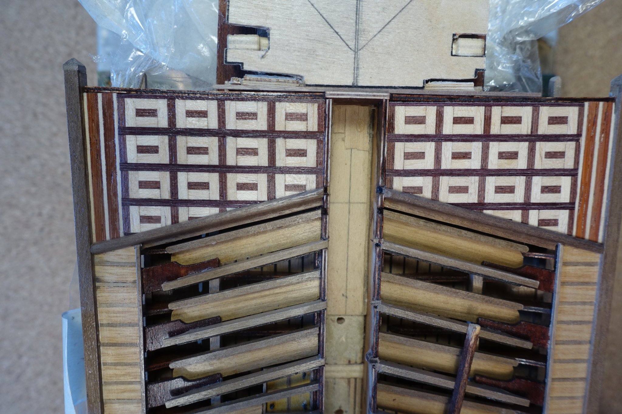
The arches are fastened and glued then the side panels are added. The top of the panels sit flush with the bottom of the lower arch slots. The attached panels make the assembly very stable and strong.
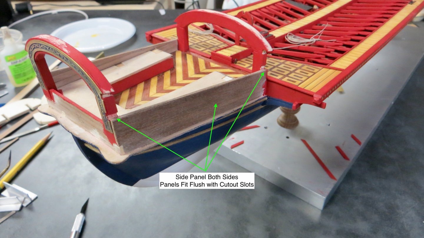
Planks are added to the inside of the side panels and painted the ship's red.
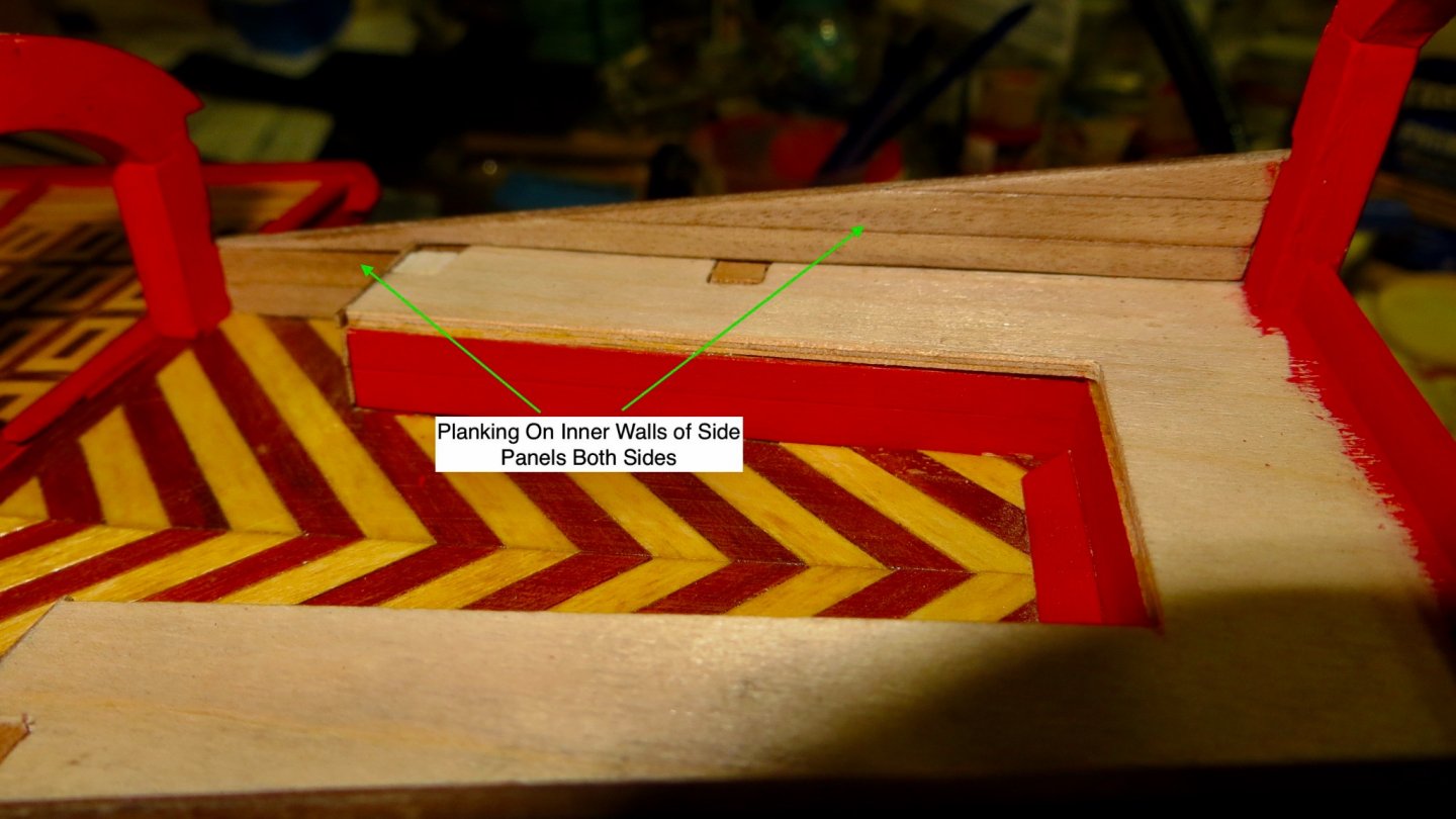
Painted panel walls

The sitting area (Top of the chest) is done with walnut strips that I cut to size and sealed with a satin based sealant.
Trim strips (all painted red and shown with green arrows) are added around the walnut seating area.
Stanchions (shown with the blue arrows) are fixed to the inside of the side panels and sanded flush to the top of the panel. The location (placement and spacing) of the stanchions are at the points where the 8 canopy arches will be located later in the build.
At this point, the lower stern railing is added. The railing slides into both lower arch slots.
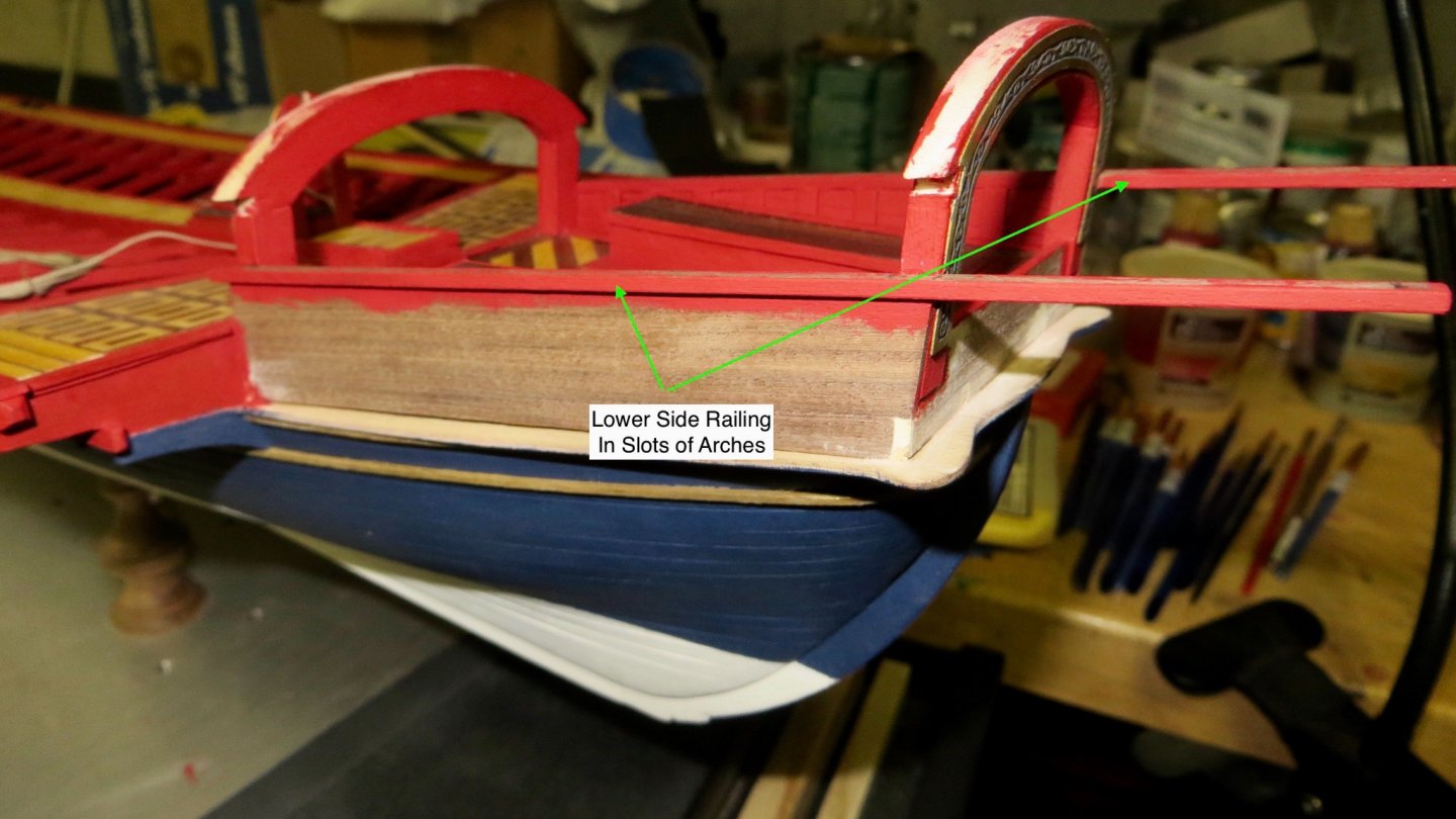
This ship model is starting to get really long from bow to stern!! lol!
Thanks,
Frank
Thanks for the excellent description and the ideas you are putting in your model. I will probably copy some of them if you dont mind. Regarding the length of the ship, I had already a discussion with my my wife were to place it. Discussion is not ready.
Again thanks for the detailed description.
Clark
-
18 hours ago, fmodajr said:
Nice work with the mahogany!
Great for the contrast you are looking for.
Frank
Thanks, I will probably proceed with the mahogany planking.
Clark
-
-
2 hours ago, Gimo said:
hi Clark
great stuff! looking really good
GimoThanks also for the inspiration.
Is the Coureur you are building, the one of CAF/Tom? I am thinking about the next project.
Clark


Reale de France by Clark – FINISHED - Corel - Scale 1:64
in - Kit build logs for subjects built from 1501 - 1750
Posted
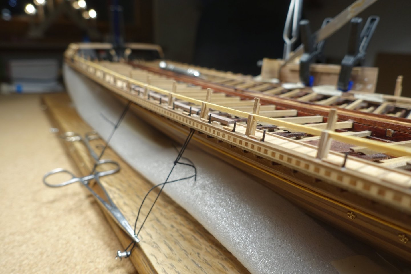
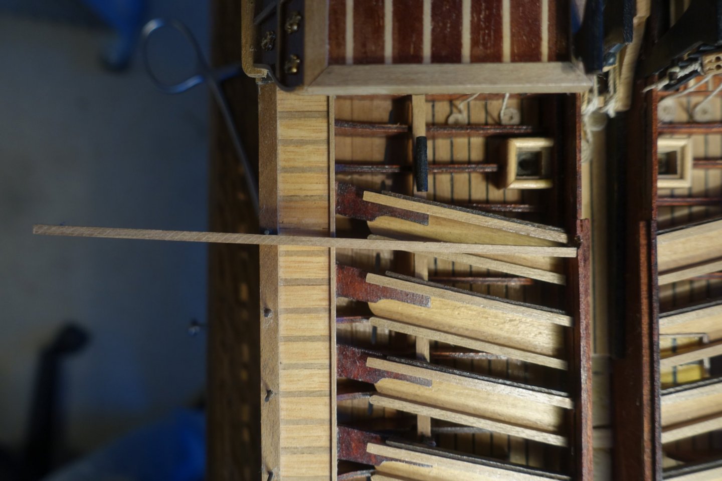
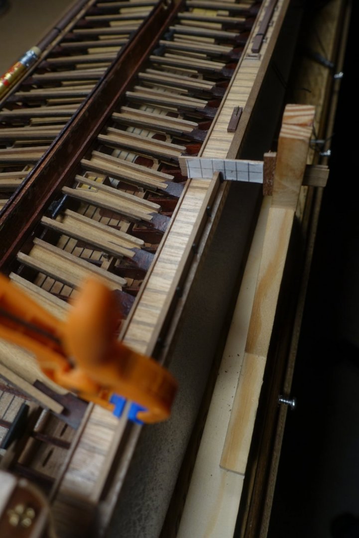
Next step was to arrange the thole pin of the oars. I hesitated if the pins had to be arranged on the bow or on the stern side of the oars, i.e. if the boat was pulled or pushed via the pins. They had to be arranged on the stern side of the oars meaning that the boat was pulled via the pins and oarloops. Gimo, thanks for providing the picture. To arrange the pins vertically, used the holder I had prepared for fixing the supports.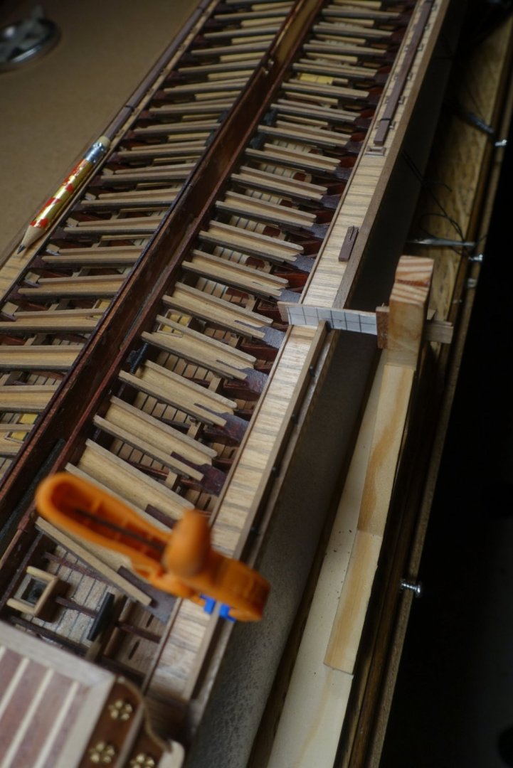
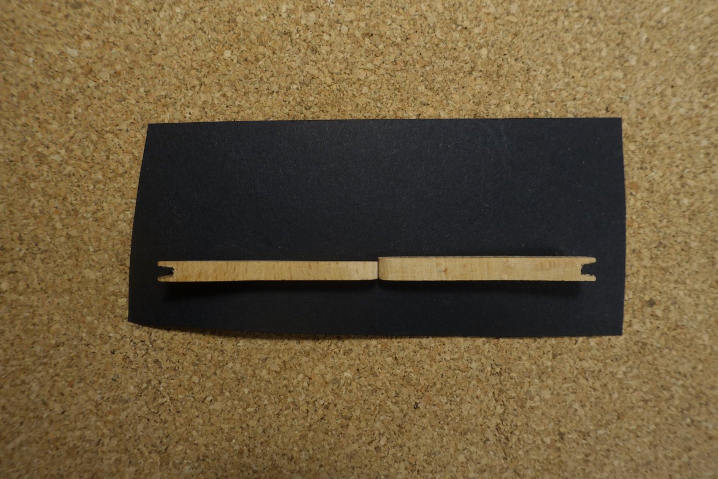
Railing stanchions were prepared out of two 2x2 mm wood strips according to Corel suggestions. To get the correct and uniform placement of the small piece on the longer one, I used a simple walnut strip with an opening cut.
To fix the stanchions on the deck, small pins were inserted. For arranging the stanchions vertically and horizontally I used the holder again.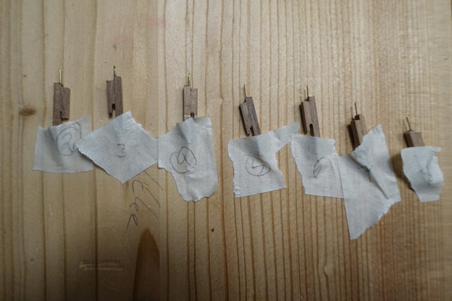
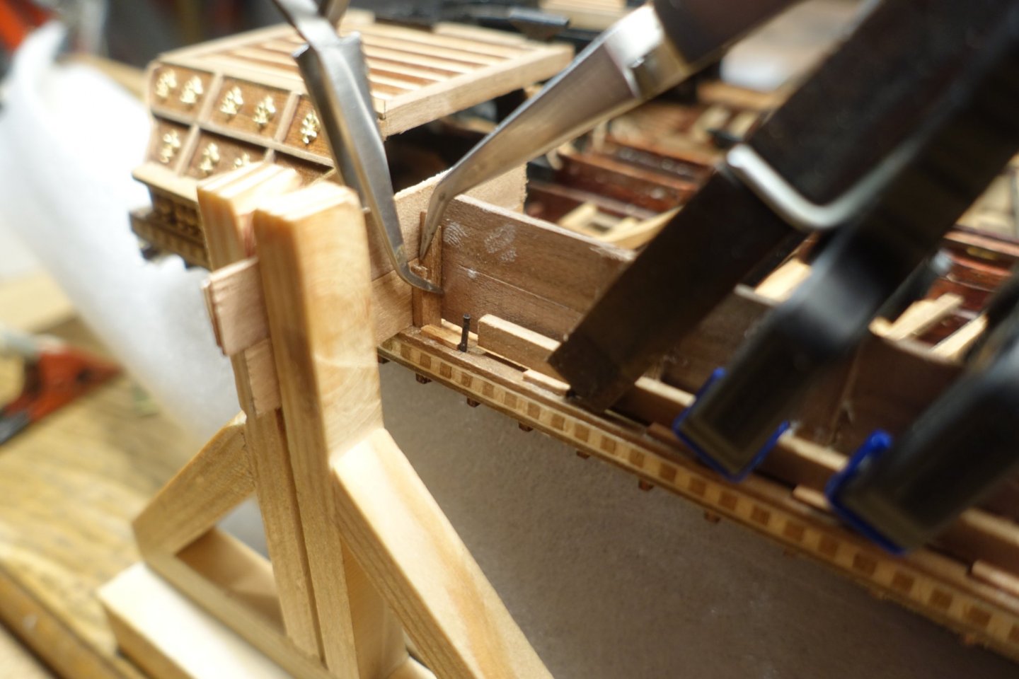
Stanchions and pins of the port side are now placed and glued.