


Clark
-
Posts
238 -
Joined
-
Last visited
Content Type
Profiles
Forums
Gallery
Events
Posts posted by Clark
-
-
4 hours ago, fmodajr said:
Very nice Clark!
congratulations !
Sorry to hear about the quality of the oars. I took a quick peek at mine and they look really nice.
Frank
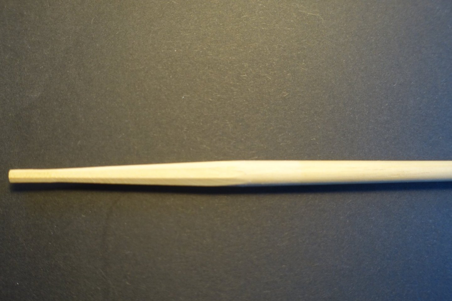
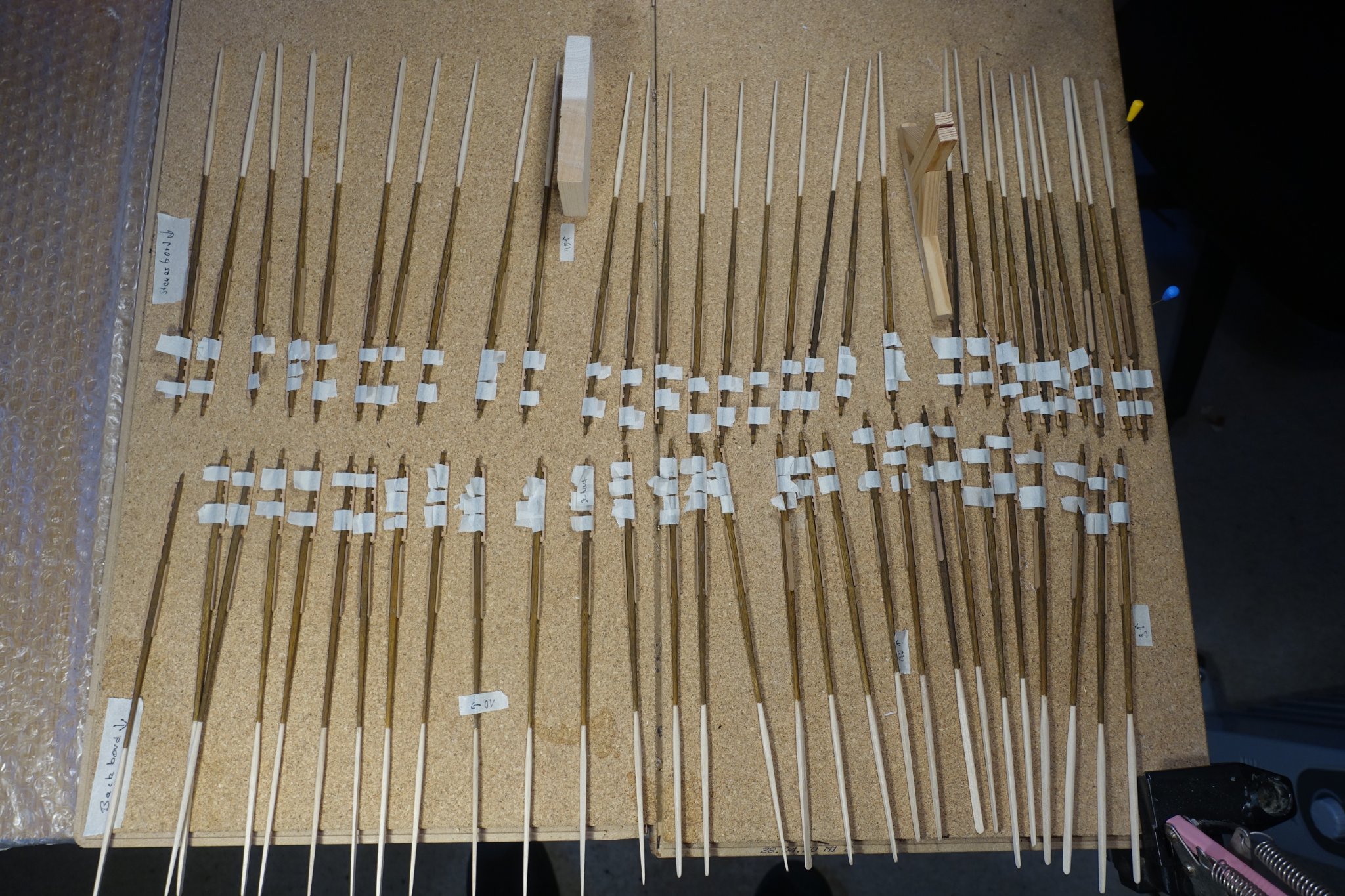
Thanks! Diameter of the thicker part of the oar blade (dont know if this is the correct name) varied between 4 and 2.4 mm. Sanded them the best I could.
-
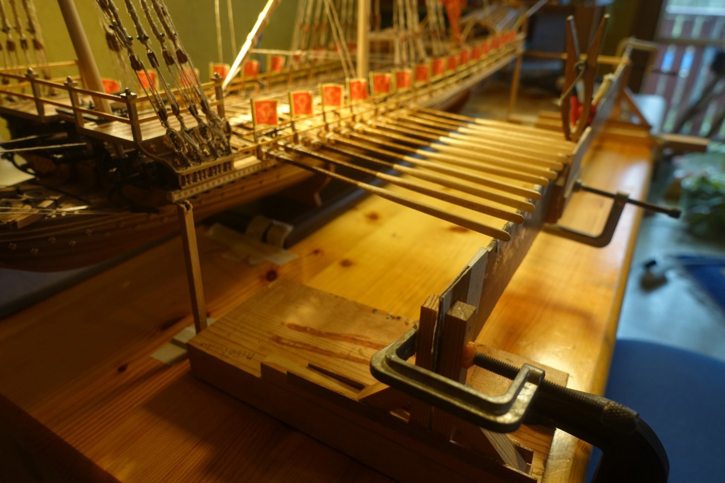
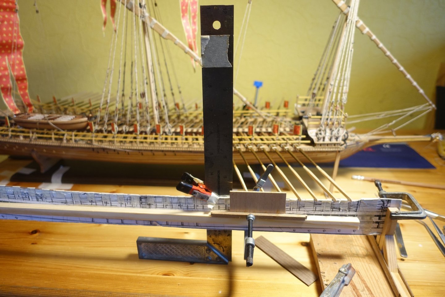
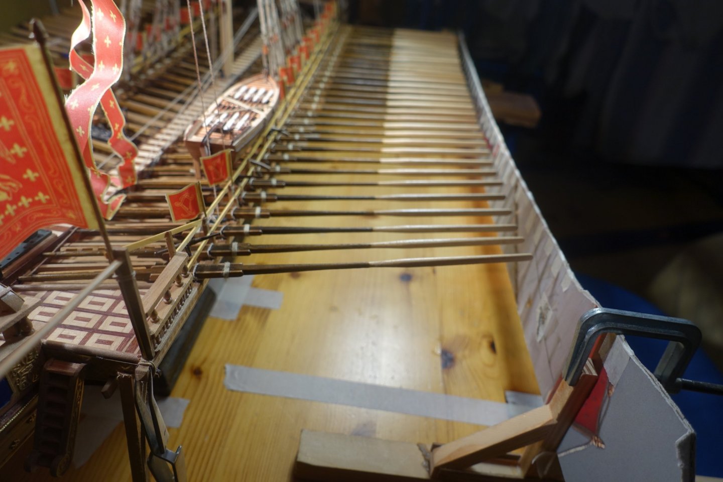
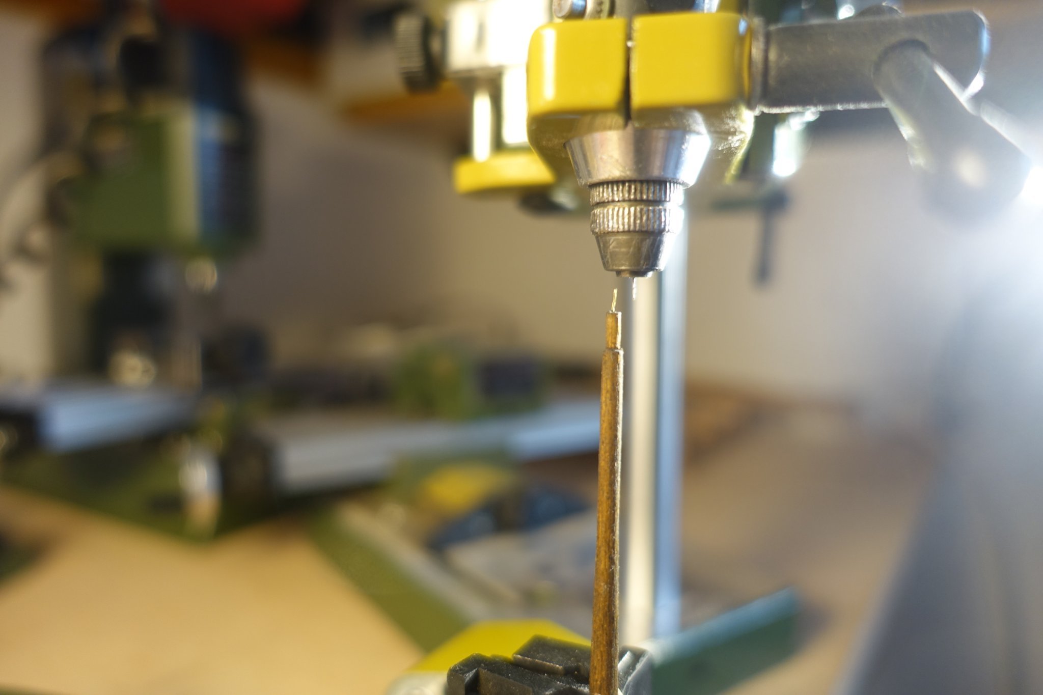
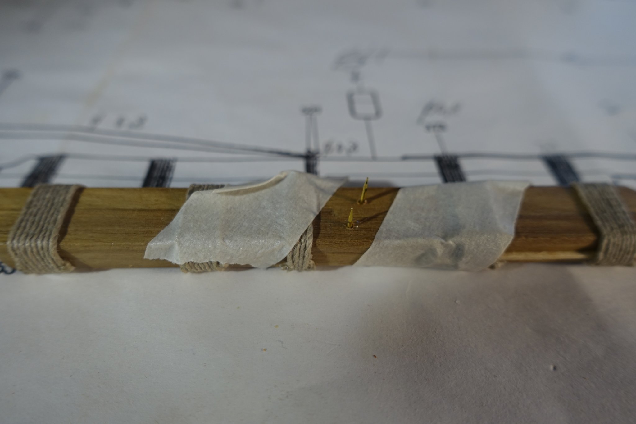
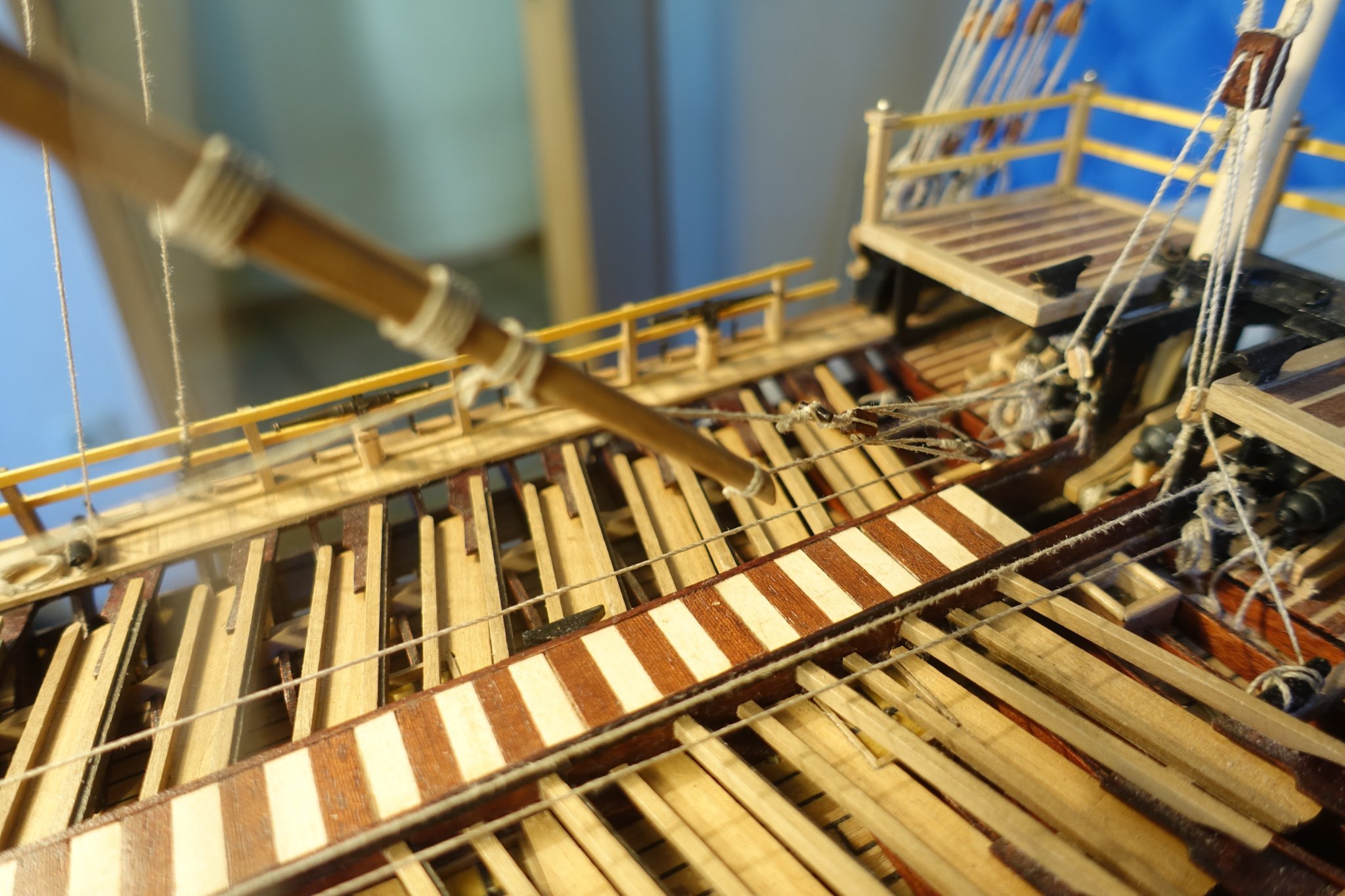
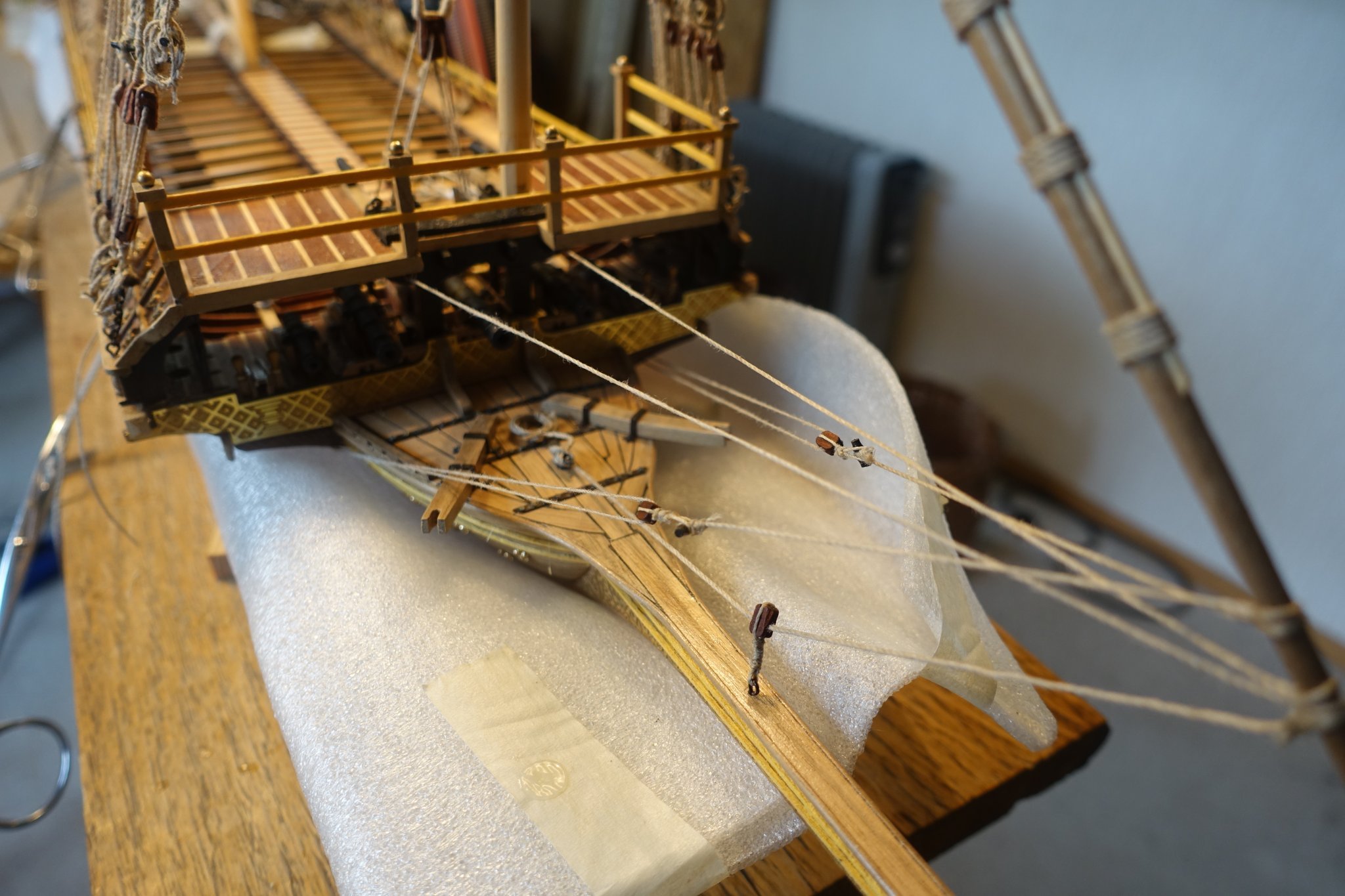
Next, the oars were prepared. The blanks from Corel had to be sanded and adjusted quite intensively. It might have been easier to make the oars from a strip with a square cross-section. Since later the ship will be visible mainly from the starboard side, I assigned the slightly worse oars to the port side. Also between port and starboard was later differentiated in the simulated attachment of the protective boards (knots/gluing on the keel side of the oars). To fix the rudders better, small pieces of wire (diameter 0.2 mm) were first sunk into the shaft. However, it turned out that these wire pins made adjusting the oars rather difficult. They were therefore subsequently ground off.
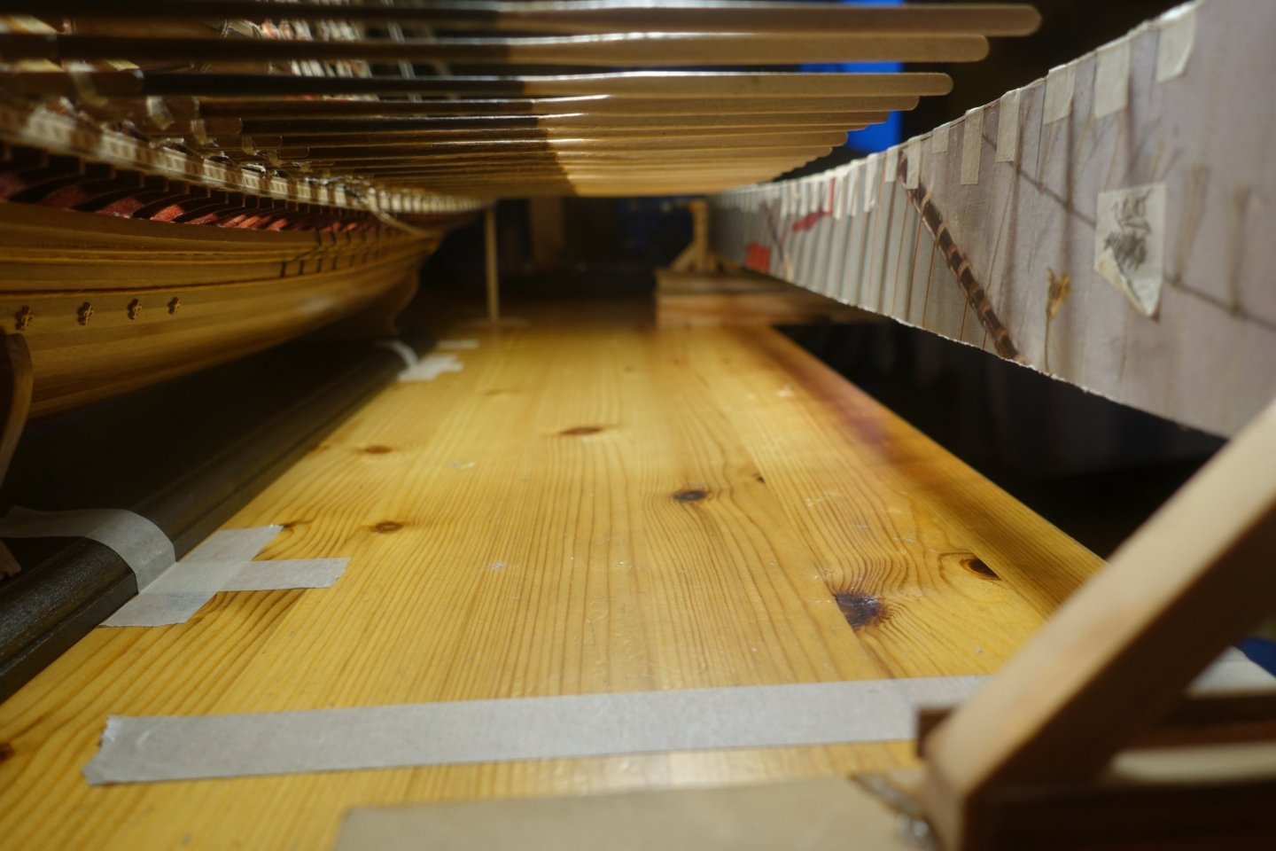
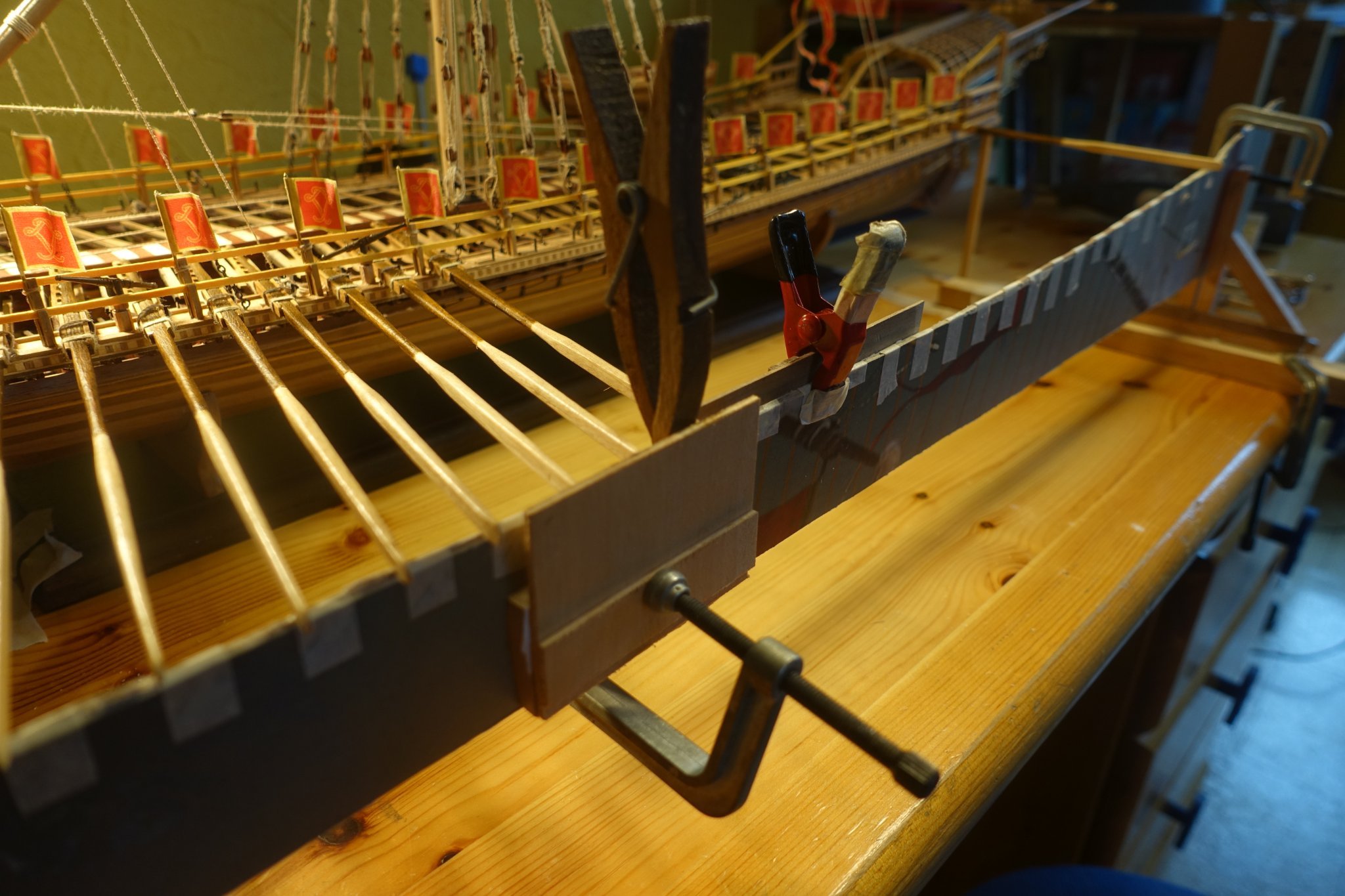
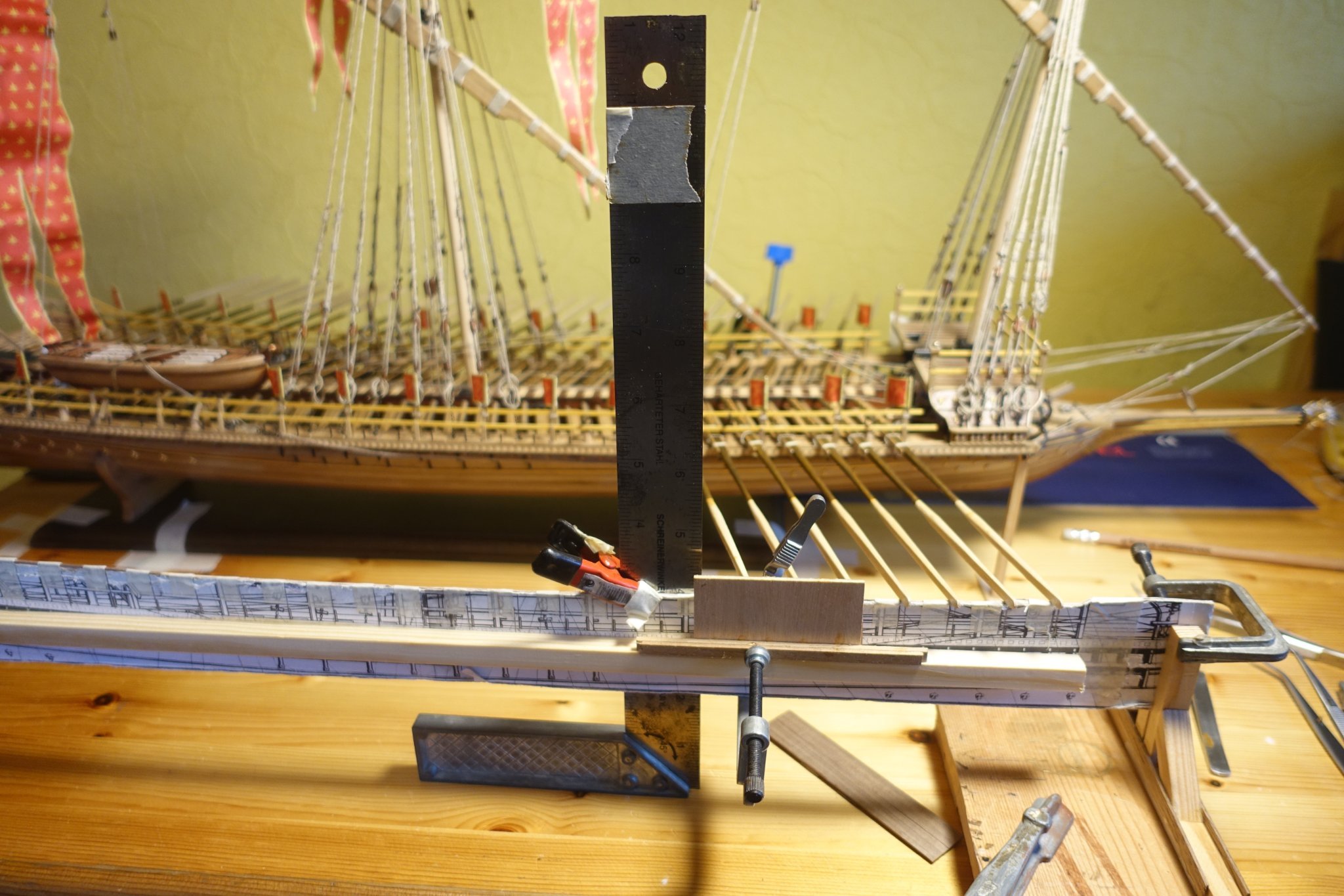
To adjust the oars on the ship, I made a template that imitated the bend of the ship's side. The distance between the oars was marked. On the outside, the oars were brought to the same distance by a spacer bar.


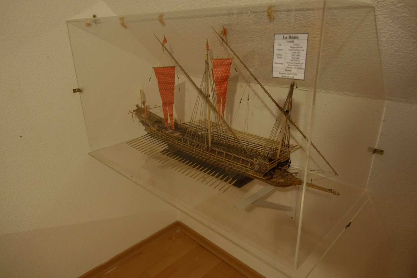
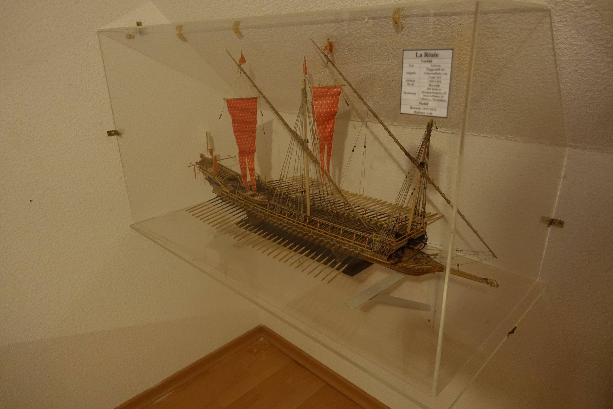
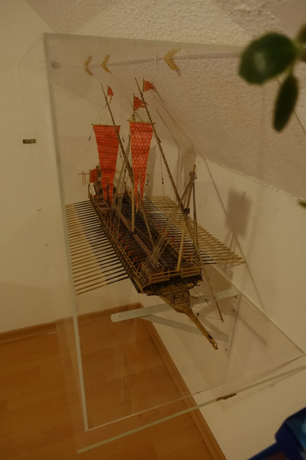
For the showcase I used acrylic glass. The showcase was mounted under a sloping roof. The easier sawing of acrylic glass proved to be advantageous here. Now in the showcase it becomes especially clear what dimensions the ship has. In retrospect, building the ship was a lot of fun even if the material from Corel sometimes left something to be desired.

- petervisser, ccoyle, GrandpaPhil and 3 others
-
 5
5
-
 1
1
-
17 hours ago, fmodajr said:
Tim, Hubac and Michael,
Thanks you all for your welcome comments.
Go figure, I finally get back into my model and immediately proceed to catch a severe flu, which has kept me in bed all week!
Starting to recover slowly though. Lol!!
Thanks again,
Frank
Hope you get well soon
Clark
-
On 11/27/2021 at 11:42 AM, G. Delacroix said:
Hello,
Except for the anchor ropes and the shrouds (I'll spare you the Mediterranean terms), the rigging of the galleys is exclusively made of high quality natural hemp and not tarred. The process of obtaining hemp fibers is more elaborate and results in more refined ropes, with longer fibers and less dust, wood remains or little oakum. This rope is called "white rope" in opposition to the tarred rope which is dark. This white rope is obviously not white but straw colored as it has been said.
The white rope is imperatively used for galleys because it has an advantage: its resistance is one third higher than the tarred rope or, if you prefer, a tarred rope loses one third of its resistance by the tar applied to it. This implies that for equivalent strength, a white rope is less thick than a tarred rope and therefore lighter and, as in a galley, the weight and strength is very important given the size of the sails, white rope is preferred.The galleys do not sail in winter (only from May to November) which avoids the problems of bad weather on the not tarred ropes.
For the chebecs whose rigging has approximately the same characteristics although of lower size, I think that the same type of white rope was used.GD
Hello Gerard,
thank you very much for the detailed answer, which really helped me and removed many uncertainties. I had so far relied on von Mondfeld with his special editions on the galleys and the ships of the Mediterranean. However, he is less informative here than with his other books. Also congratulations on the galleys video (La Fleur de Lis) which helps explain a lot.
Clark- mtaylor and G. Delacroix
-
2
-
-
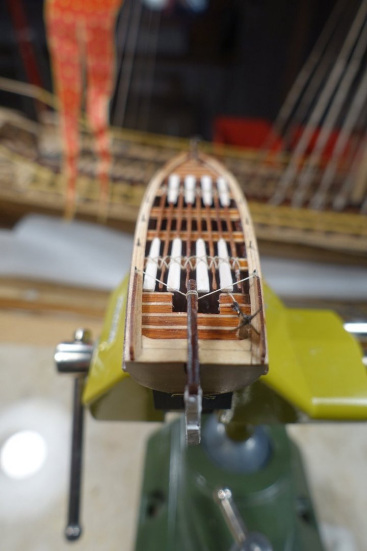
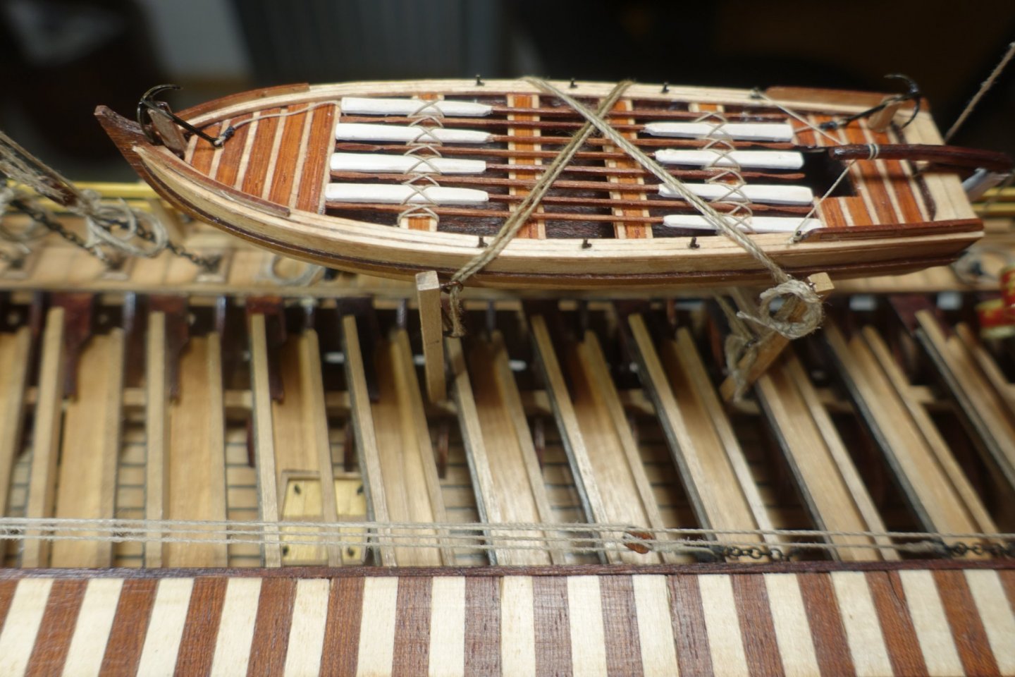
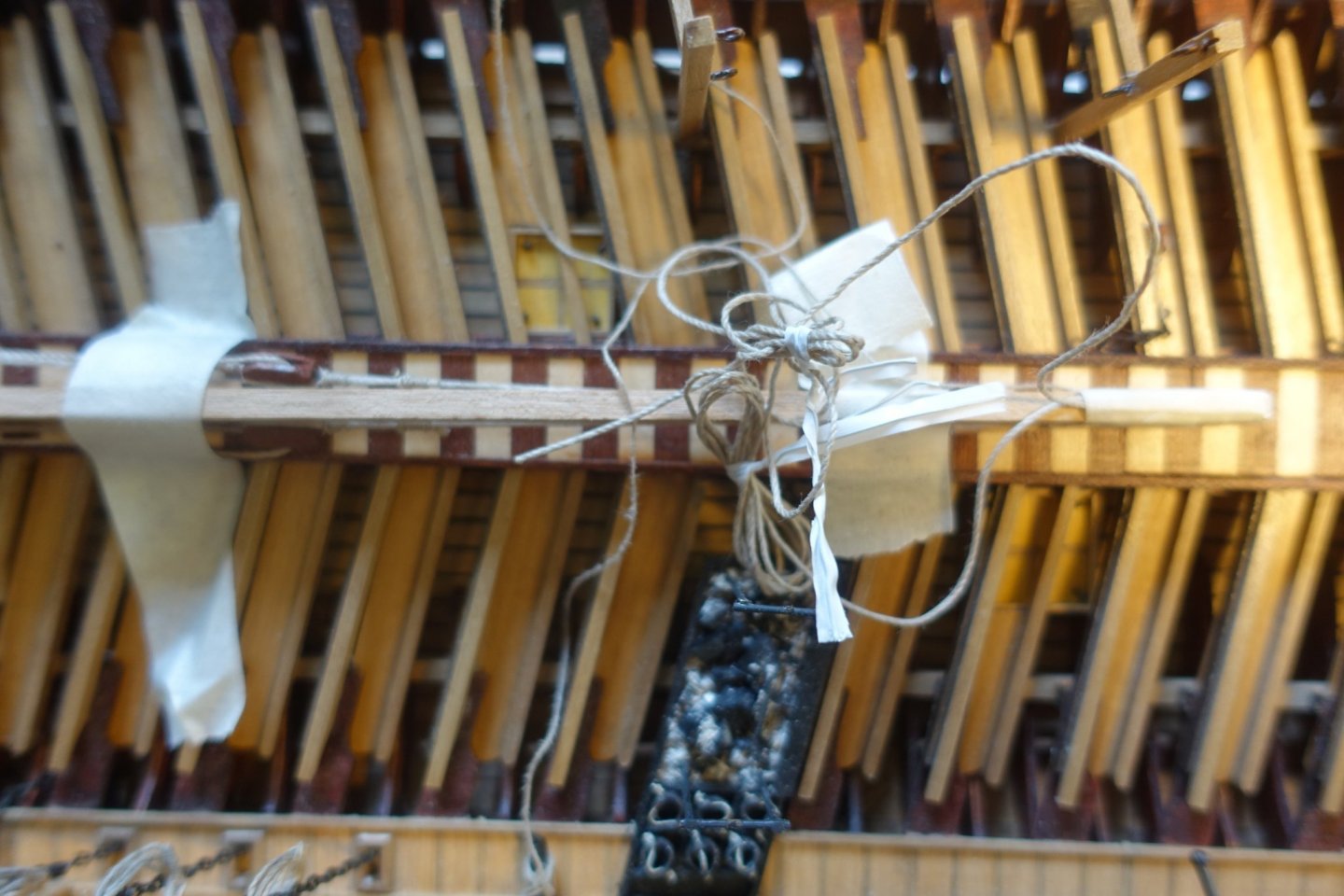
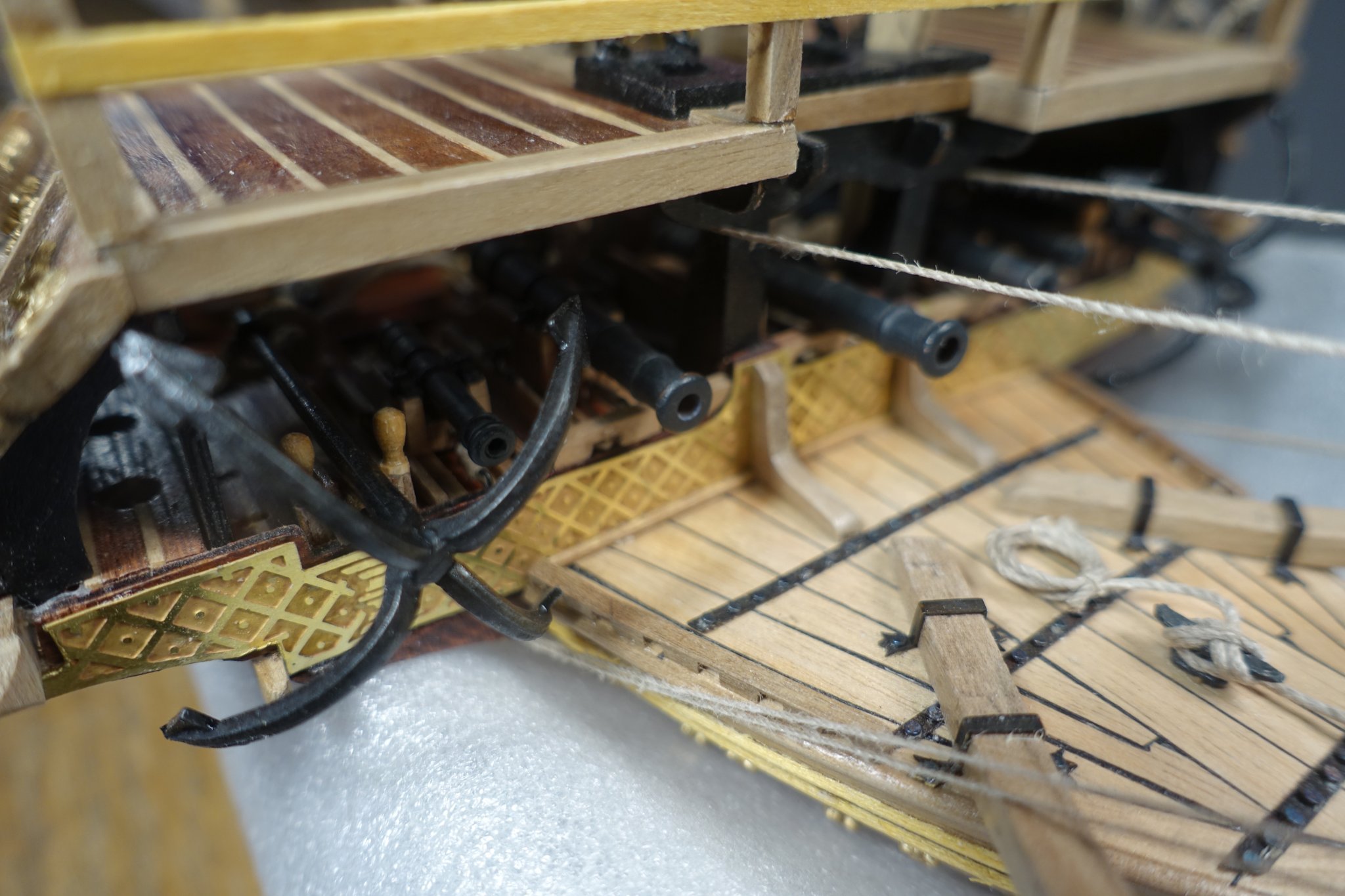
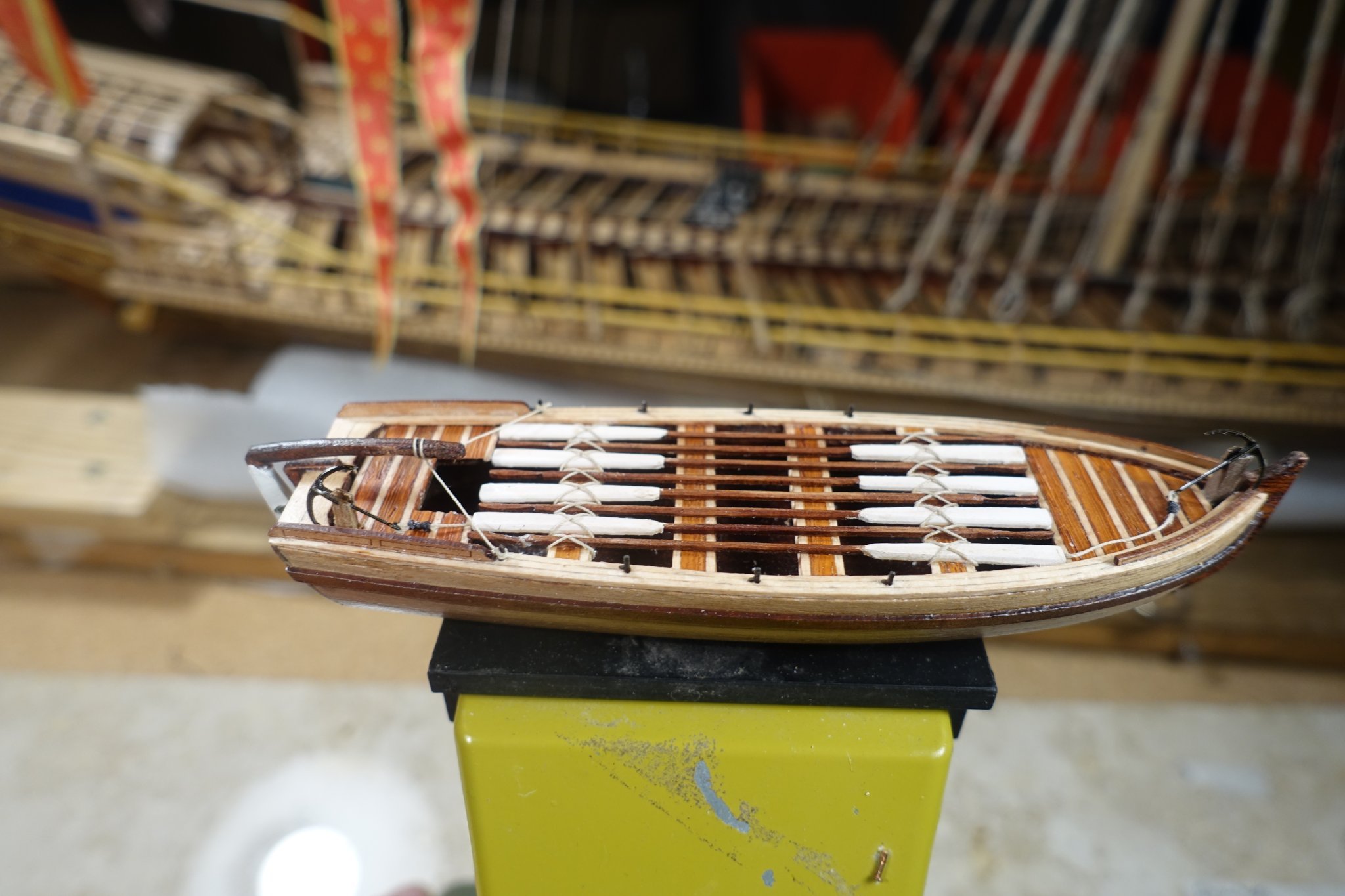
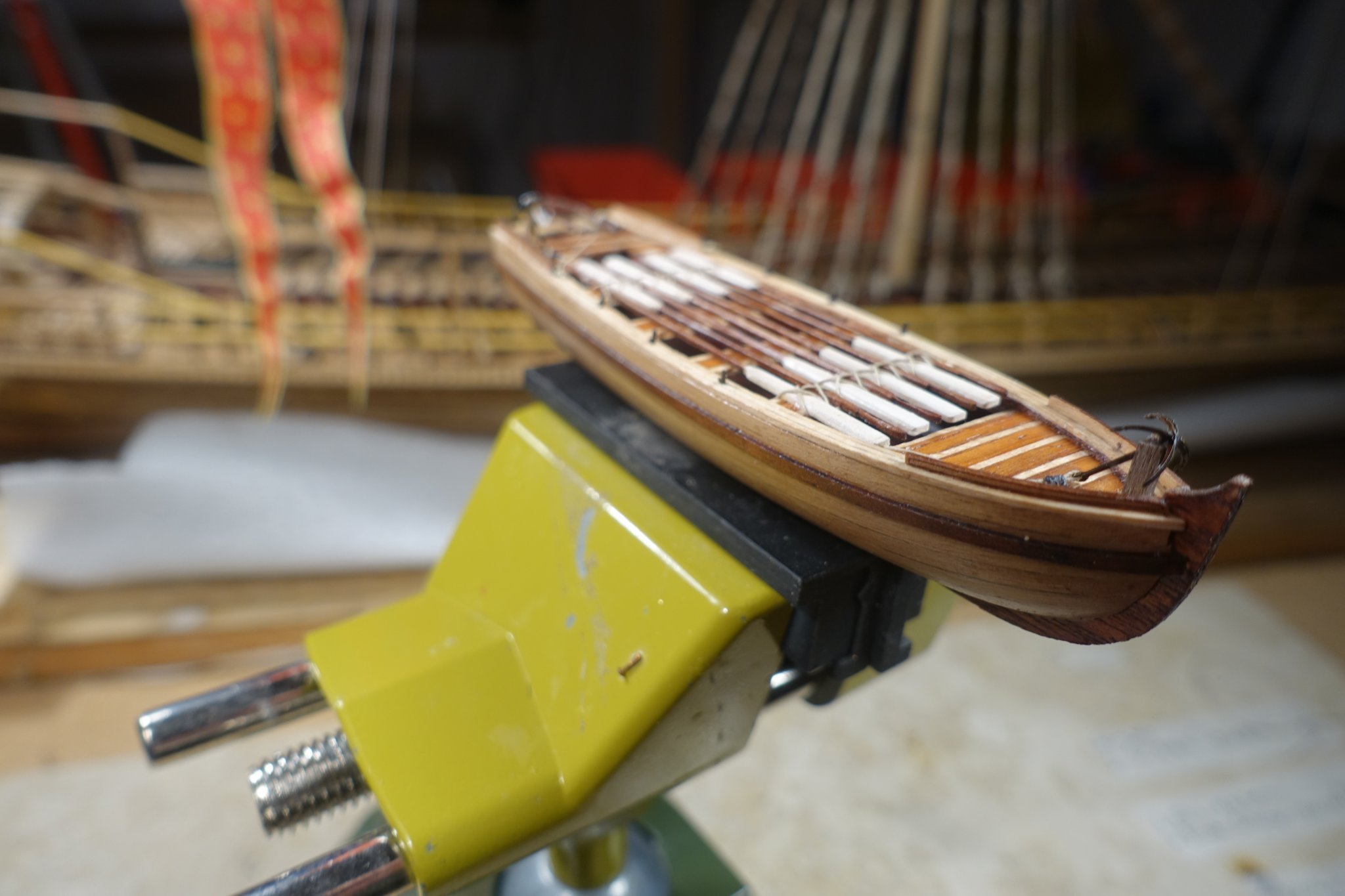
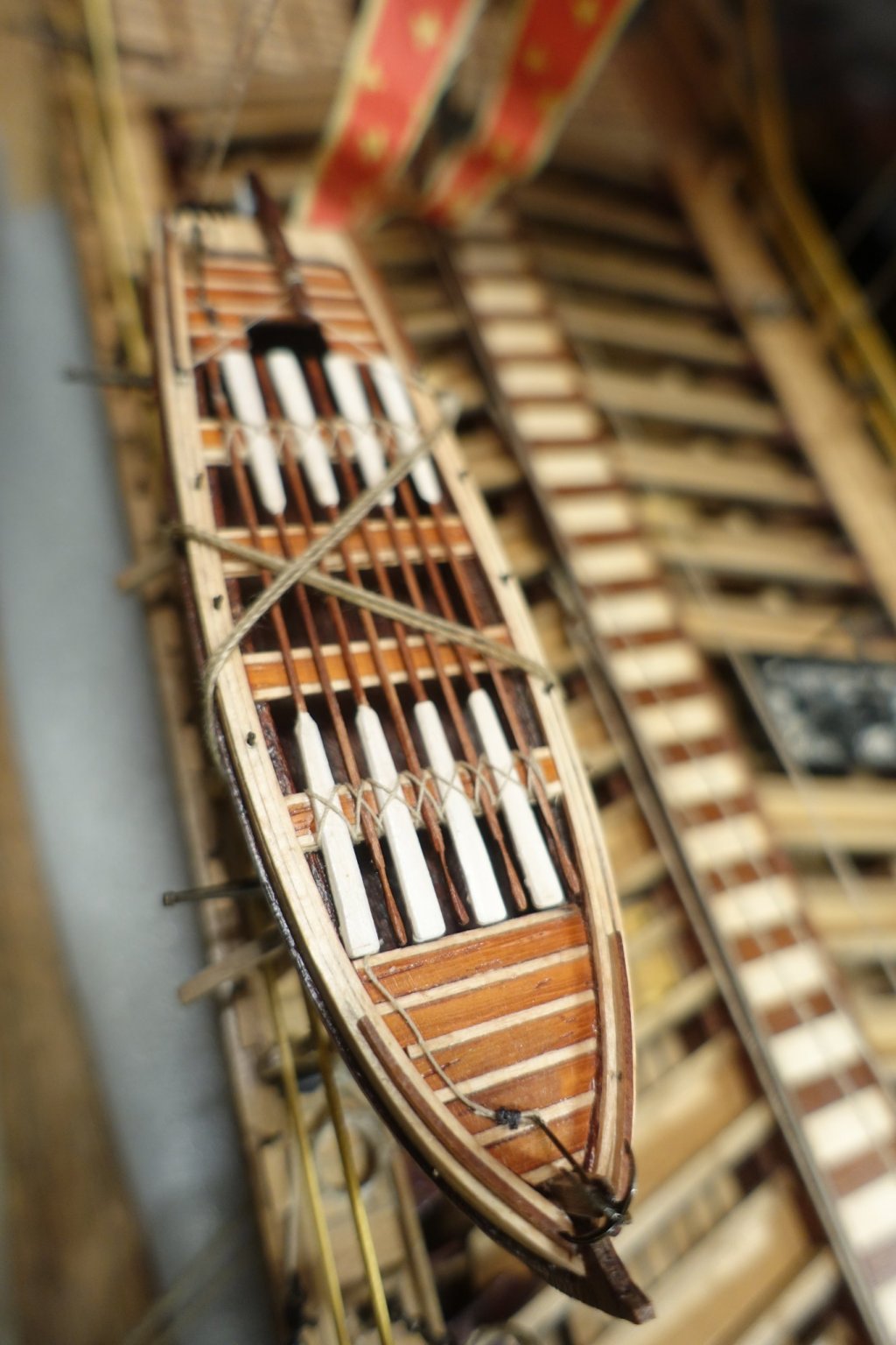
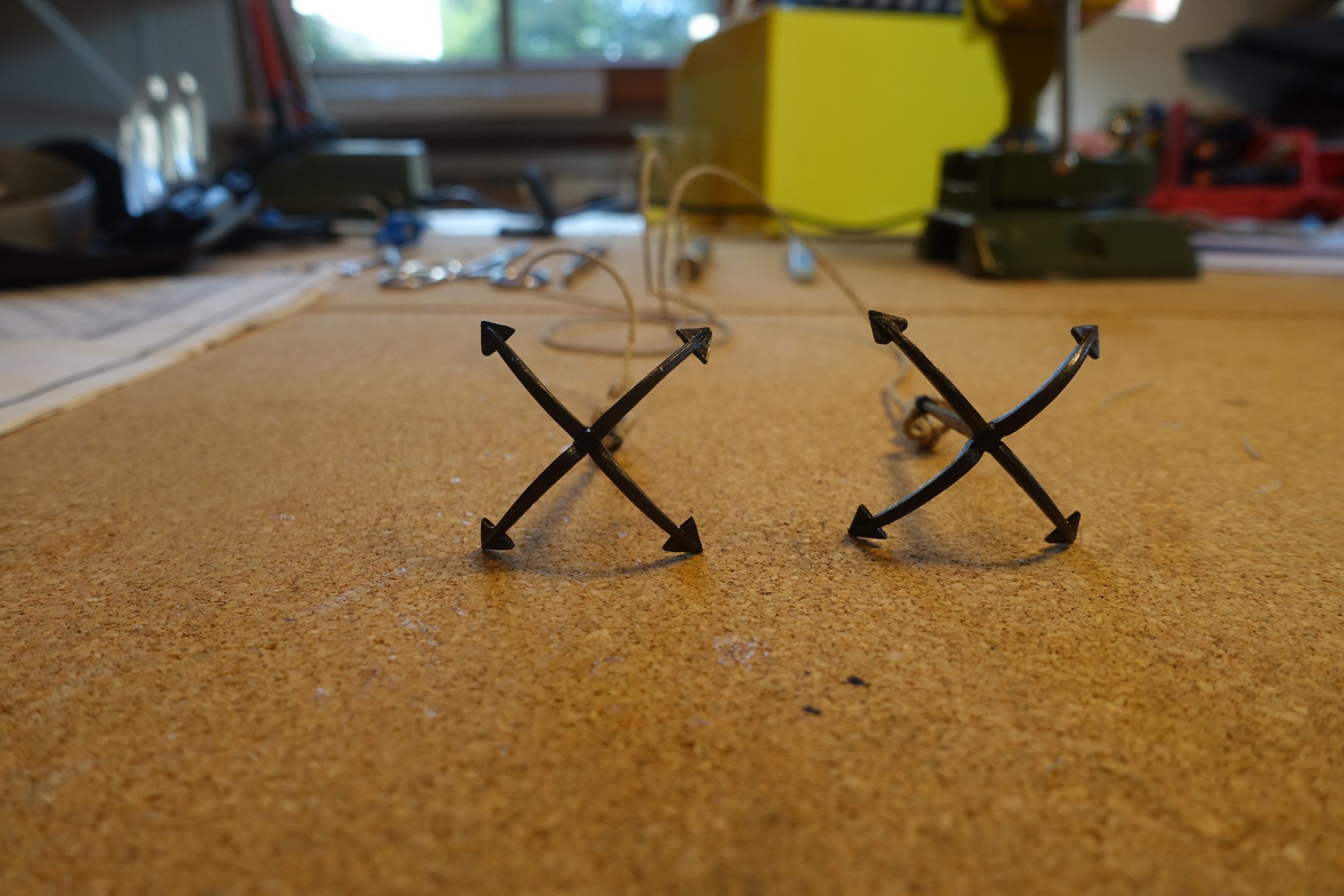
In the last few weeks I have finished the anchors, the flags and the dinghy and attached them to the ship.
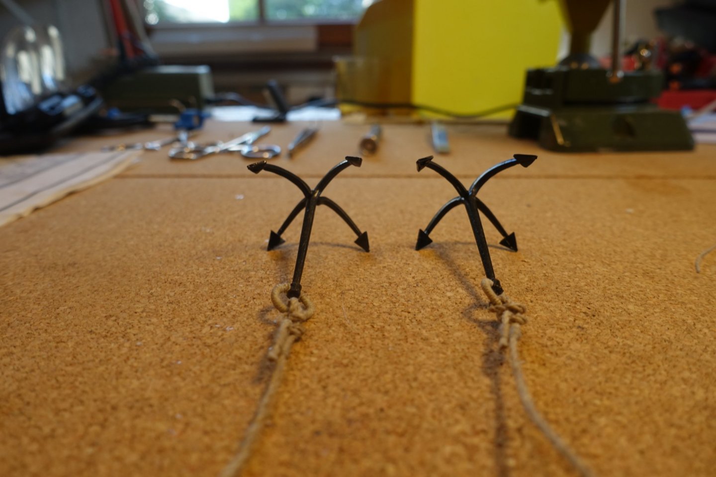
The problem with the Corel anchors is shown in the previous post. Regarding the exact bearing of the anchors, there was a discussion on safemaster's blog:
https://modelshipworld.com/topic/20561-reale-de-france-by-safemaster-heller/page/7/
In the end, Gérard Delacroix convinced me, his video is quite compelling and contradicts Corel's presentation:
https://www.youtube.com/watch?v=YYxrbtuyNG0.

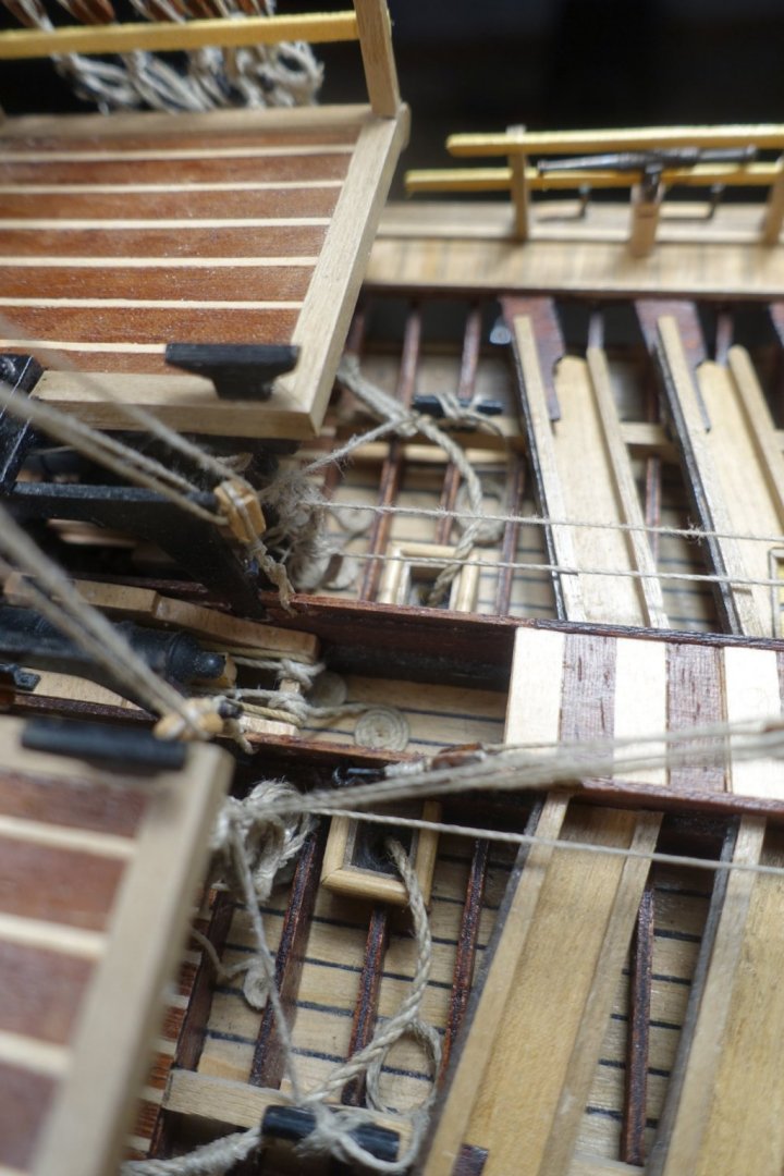
In my opinion the anchor ropes have to be guided tightly. Therefore, they are guided directly into the box.
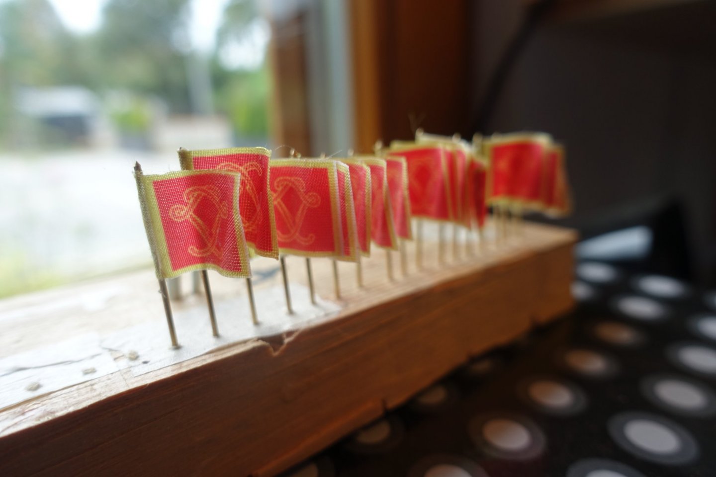
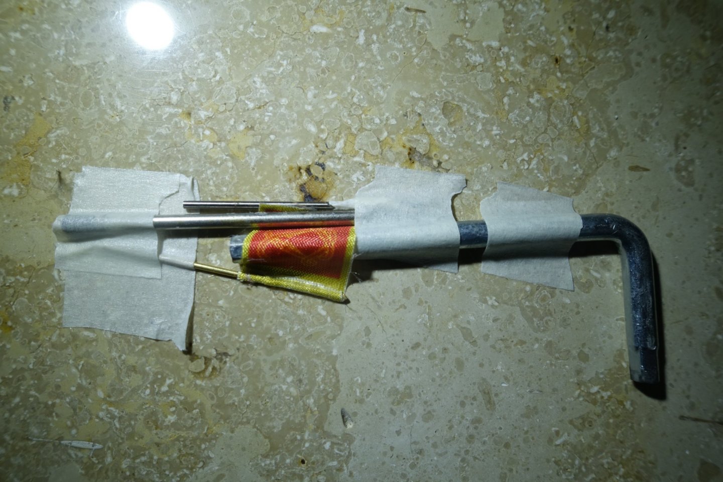
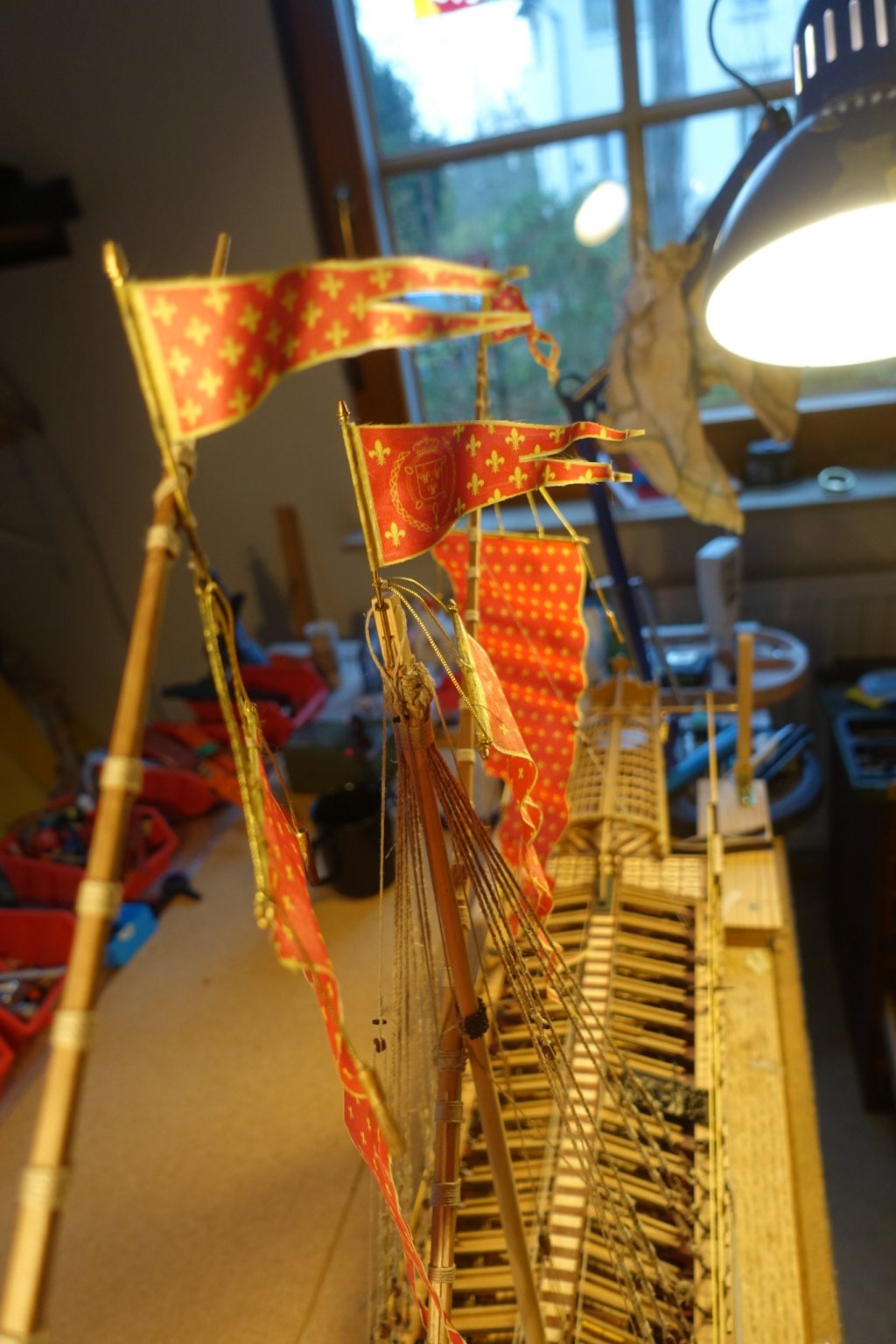
For the flags, movement due to the wind was simulated with highly diluted PVA.

For the dinghy, material was also used that came from Chris https://vanguardmodels.co.uk/product/ships-boats-various-types/.
It's not quite contemporary this way, but I liked it better this way.


Next I will work on the oars and think about the construction of the display case.
- fmodajr, 72Nova and GrandpaPhil
-
3
-
-
The "Krick" dregg anchors only had to be slightly deburred. Following von Mondfeld's description, galley anchors were fastened with a special stay. I put the ship aside for the time being, so the anchors are also in stock and will only be attached later. The next thing I want to do is the dinghy.

- GrandpaPhil, fmodajr and Archi
-
3
-
17 hours ago, fmodajr said:
Hi Clark,
Wow, those anchors are in bad shape. Can you heat them and bend them back?
Or will you make new ones?
I'll have to check my set to see how they look!
Looks like you're nearing the finish line!
thanks,
Frank
Hi Frank,
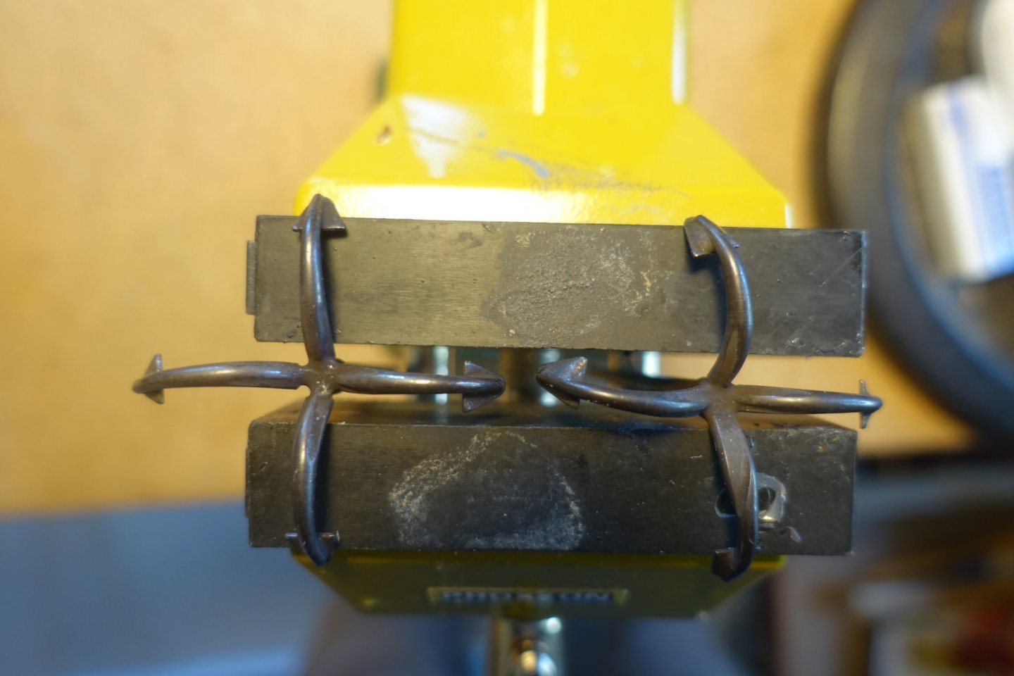
Not only are the anchors bent, but the right one has a depression on the lower blade arm. I ordered new ones from "Krick" (German specialist dealer), they arrived yesterday and look excellent. I had tried to make anchors myself on a previous ship, but it was not successful.
How are you doing with the move? Ships secured?
All the best
Clark -
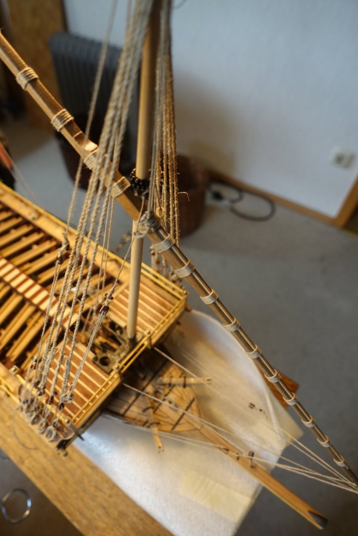
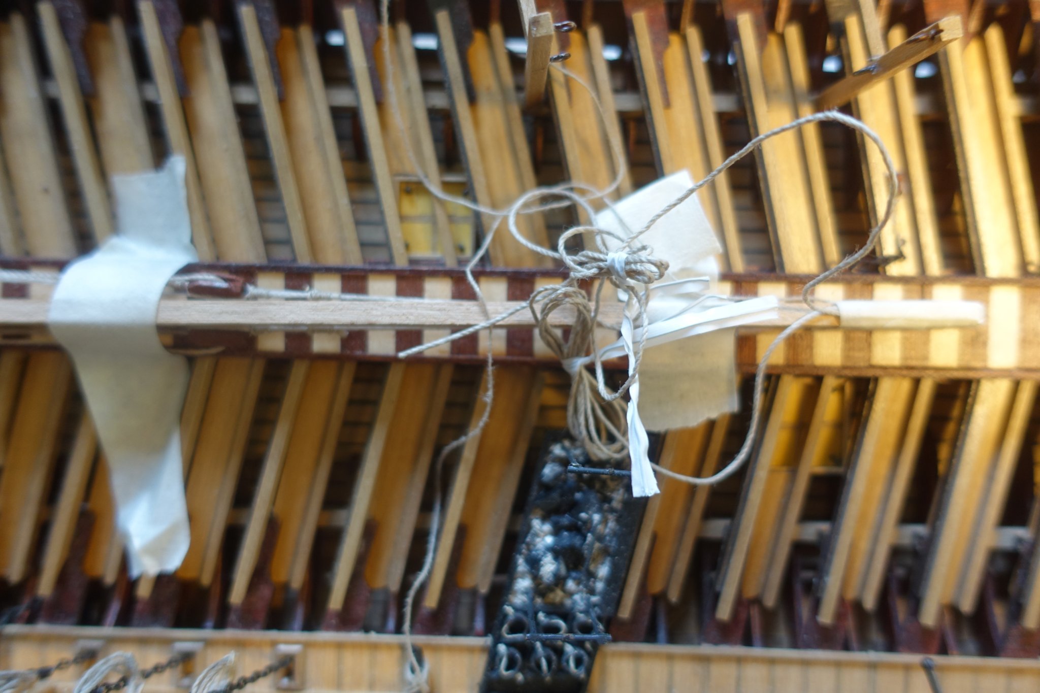
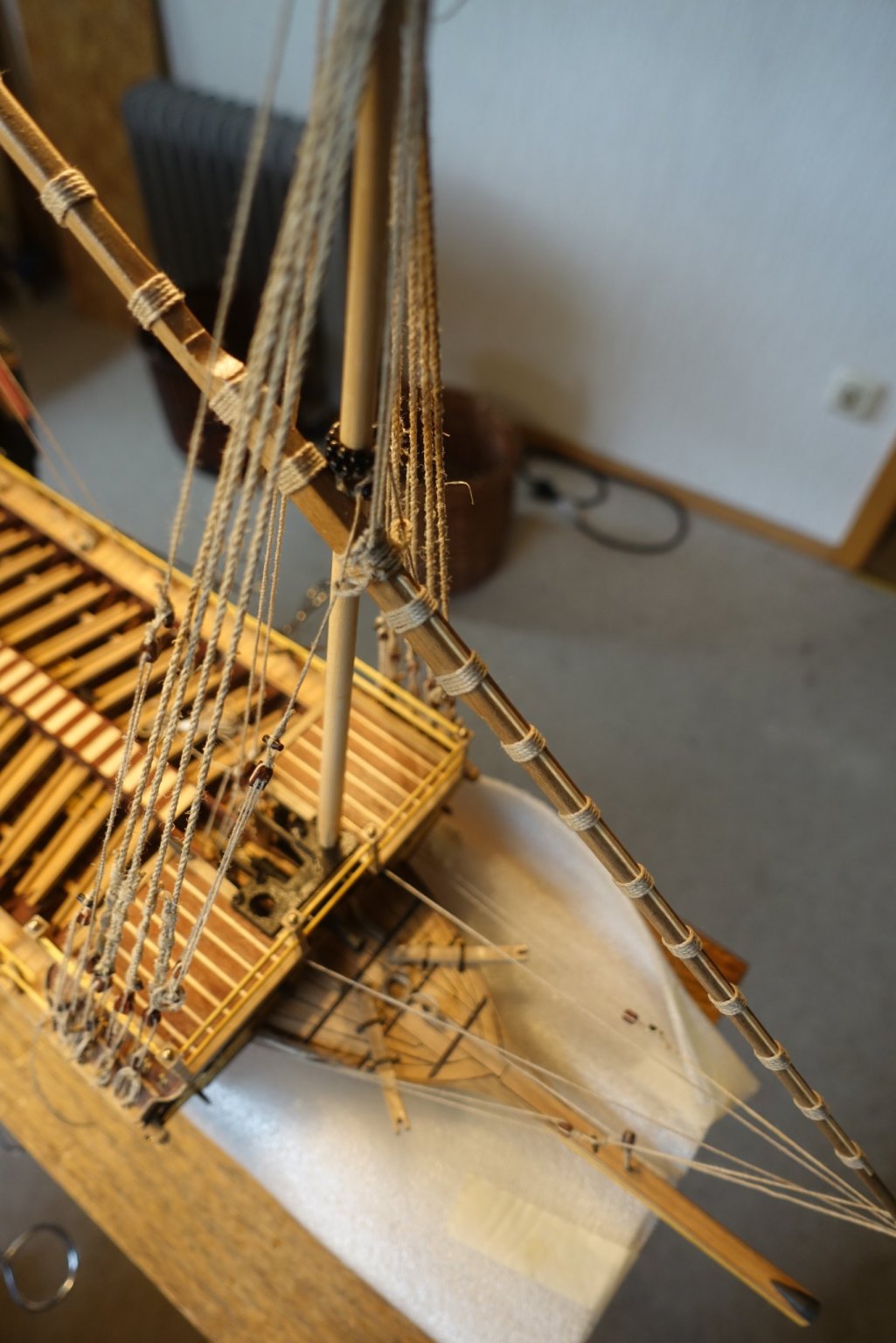
The main lateen yard is now fixed. The first fixation was again done with two small nails, countersunk in the yard.

The ropes for the halyard were fixed before. As they pass through the centre aisle and are attached to the pins of the forecastle, they were mounted before the covering the centre aisle.

As there are no sails attached, I fixed the yard slightly eased.

Actually, I then wanted to continue with the anchors, but found that they were considerably bent and also inaccurately made. Another point that turns me away from Corel.
- 72Nova, fmodajr and GrandpaPhil
-
3
-
Preordered two weeks ago, Sphinx arrived today. Chris, do you ever sleep?
Thank you very, very much!Perfect.
Clark
- Canute, chris watton, mtaylor and 1 other
-
4
-
Back at the shipyard after a long time. Our house (wood) was in need of an intensive refreshing and touching up, so the warm months were needed for that.
The fore lateen yard is now fixed. I pondered for some time whether to show the sails and decided against it. The lateen sails are quite large and catch the eye. Reefed sails usually look rather fake, my attempts with paper etc. on the previous ships were not quite satisfactory.
The attachment to the foremast was done with two small nails (unfortunately no photo taken), so that the rigging was then easier to attach. I partly deviated from the Corel plan with regard to the rigging and the belaying, as some things seemed illogical to me (conflict with the oars).

- GrandpaPhil, Danstream, fmodajr and 1 other
-
4
-
3 hours ago, chris watton said:
Only once I have cut all parts and have everything except plans and manual (as these are done locally). If there were any problems with the PE or anything else after taking people's money, I would be devastated if I had to delay the release. Hence waiting until alI is with me and have checked everything over.
Thank you very much for the quick reply. It is more than understandable that you want to be on the safe side. I will exercise patience then. Good luck and success to you and James with the wonderful model.
Clark -
14 hours ago, glennard2523 said:
I will be buying one of these kits when the order goes live.
Is it already possible to send an advance order?
Clark
- chris watton, mtaylor and KentM
-
3
-
-
-
7 hours ago, safemaster said:
Hi Clark,
I love the work you're doing on this, the lack of color gives this a whole different look that's quite pleasing to the eye👍
Michael D.
Hi Michael, I am also following your blog. It is a different approach. I especially like that you show the sails secured. When I get to that point, I'll ask a few more questions on your blog. I assume, however, that you are then finished with your Reale.
Continue to have fun
Clark -
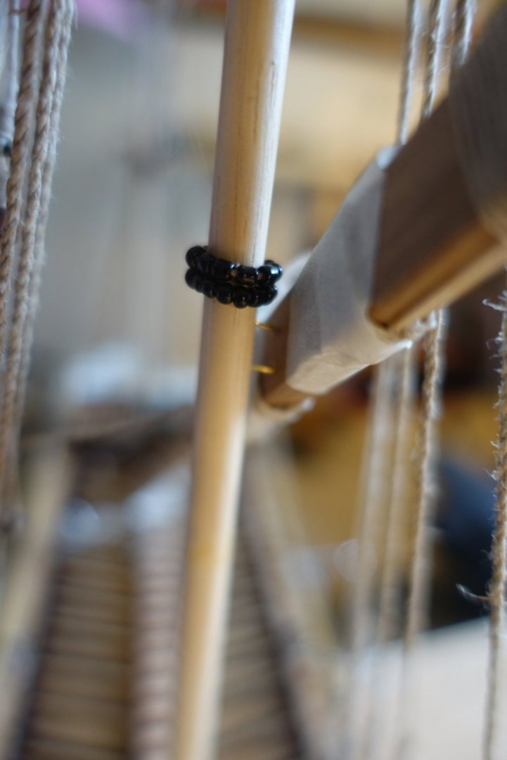
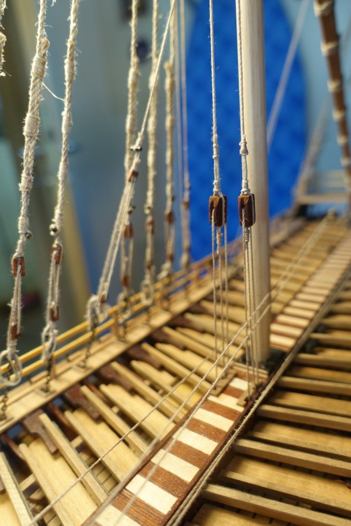
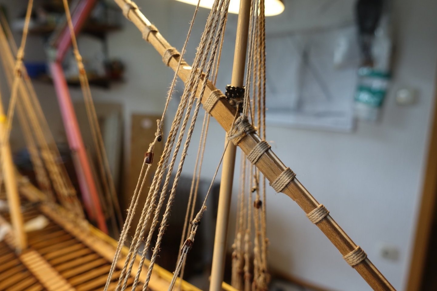
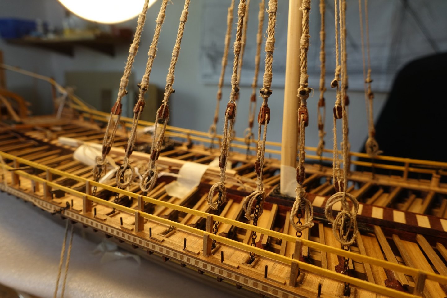
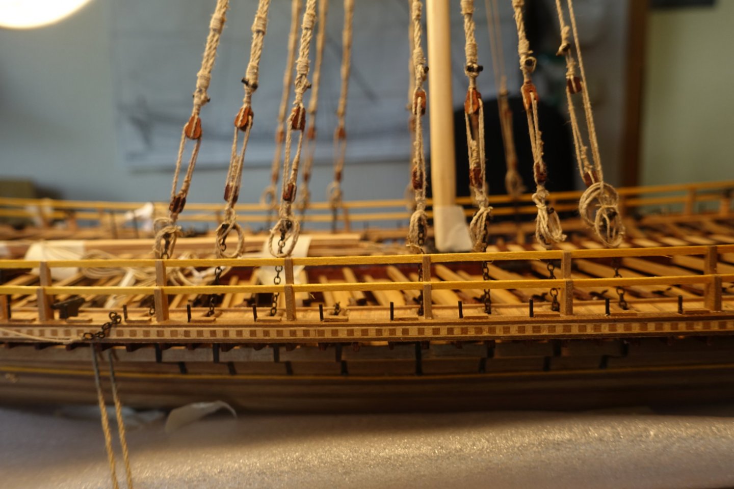
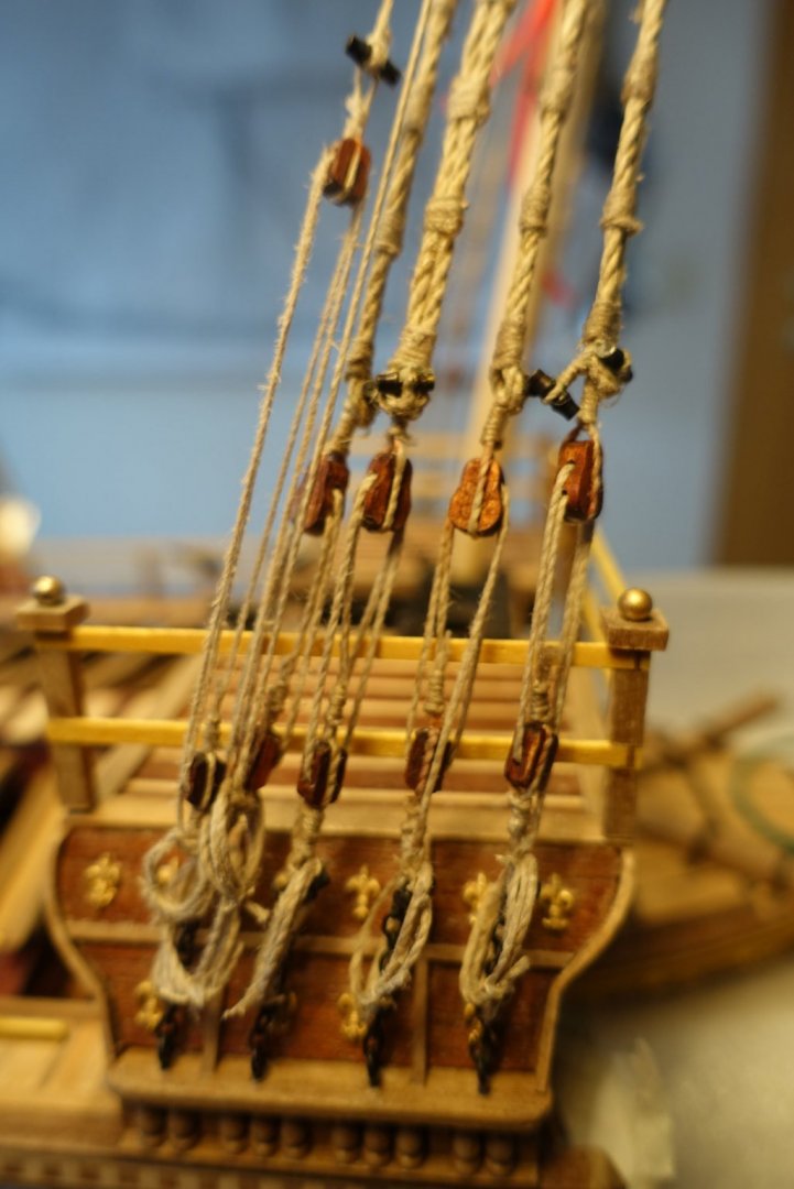
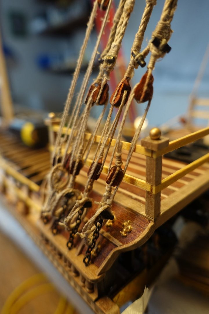
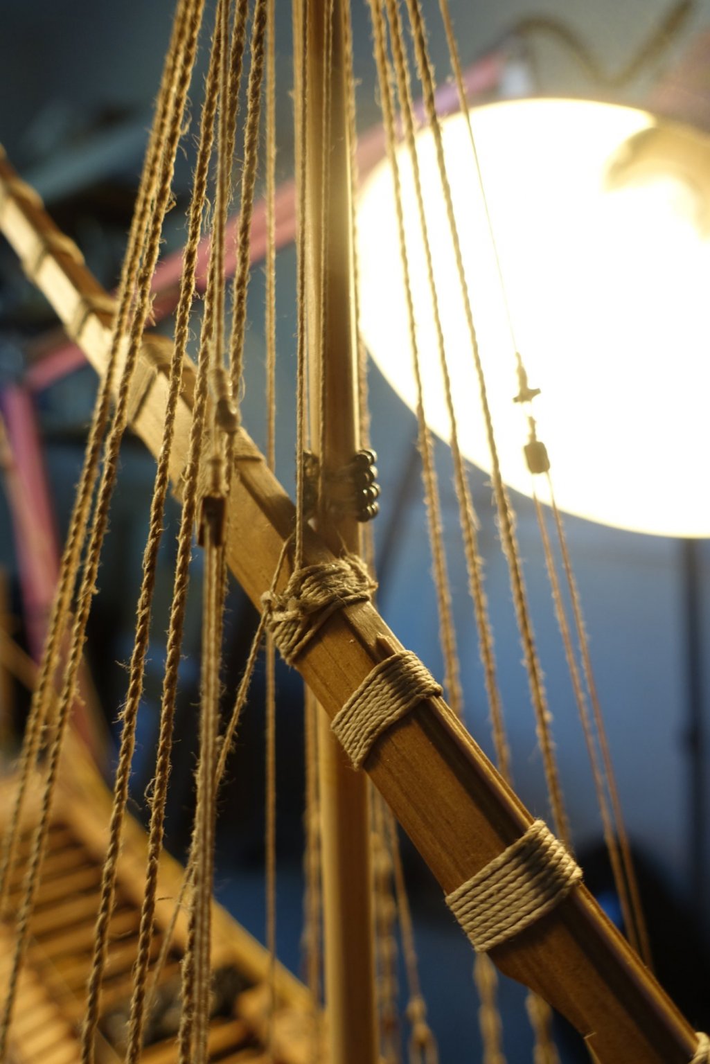
Main mast was prepared and fixed similarly to the foremast. A little bit surprising for me, backstays have to be fixed at the first chains/toggles (seen from the bow) when following the description of corel. I followed it. The fifth chains/toggles are still left free for the later attachment of the rack lines.
Clark
- GrandpaPhil and 72Nova
-
2
-
3 hours ago, Bob Cleek said:
True, but I've never had one break on me like surgical scalpel blades are won't to do. There is an advantage to the heavier gauge metal of hobby knife blades. By the way, surgeons will generally only make a couple of cuts with a scalpel before exchanging it for a new sharp one. Scalpels aren't designed to hold their really sharp edges for any more than about that.
It's odd, but nobody's mentioned sharpening hobby knife blades. A fine sharpening stone, or a leather or MDF stropping wheel charged with green polishing abrasive, or even some fine sandpaper, will put a new razor-sharp edge on a hobby knife blade in seconds. I have a very old Arkansas sharpening stone which was designed for sharpening old fashioned straight razors. I use it to keep a sharp edge on my hobby knives. It works fine.
Sharpening works quite well when using the sandpaper tools delivered by proxxon. I got both needles and blades sharp enough . There is also a rotating sharpening stone available by proxxon I usually start with the blades.
Clark
- Canute, mtaylor, thibaultron and 1 other
-
4
-
19 hours ago, chris watton said:
Yeah, you would need to make a new figurehead, as Sphinx is the only one of this class I will be developing. Am hoping this will be ready for around July.
So July will be Chrismas time.
Clark
- chris watton, Rustyj, mtaylor and 2 others
-
5
-
1 hour ago, wefalck said:
I have three of them in different sizes, but mainly use them on my milling machines.
Fixing them to the base of the PROXXON-drill could be somewhat inconvenient, but the original vice could not be screwed down either. Not sure about the current arrangements.
The 1" vices have four holes on the sides tapped M4 and two at the bottom. I cut two pieces of small angle iron or aluminium the length of the vice and drilled holes to match the four tapped holes. The angles were screwed to the sides and had a number of holes in the horizontal part with which it can be screwed to machine tables.
The larger vice have horizontol through holes (I think 6 mm) for a round rod that goes through the lug with which the moveable jaw is screwed down. I made a 6 mm rod and cross-drilled it with 3 mm to take some long M3 screws with which to tie down the vice onto machine tables. The vices also have to round notches at the end for simple hold-down clamps.
If you think of getting one of the 1" vices, make sure you get one with the shallow recess on top of the jaw - this comes very handy for small pieces. The others don't seem to come with this feature.
BTW the vices may also run under the name of EDM (Electrical Discharge Machining) vices, where they are used to hold the electrodes.
I didn't check, whether RDG Tools do have these vices, but thought that I bought one of mine from them. But I may be wrong, as this must have been some 15 years ago.
Hi Dave, hi wefalk
Using the vice of proxxon makes drilling and even sanding really easy but I would agree that fixing to the drilling table is a bit challenging in that you have to be sure to adjust it rectangular. I put a long strip (100cm) in the vice (MS4), adjusted the drilling table (KT70) rectangular to the edge of the work disk and measured and adjusted the deviation of the strip of the edge of the working disk. When no deviation was visible, screws were tightened.
Clark
-
6 hours ago, Gimo said:
Very precise masts preparation. Very well done Clark.
Gimo
Thanks!!
-
1 hour ago, fmodajr said:
Great job on a tough section of the ship model.
Looks like you put a lot of time and thought into the process!
Frank
Thanks, the Reale is a great challenge in general. Good luck with your build.
Clark
-
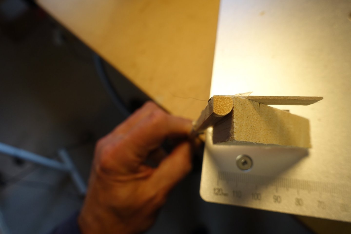
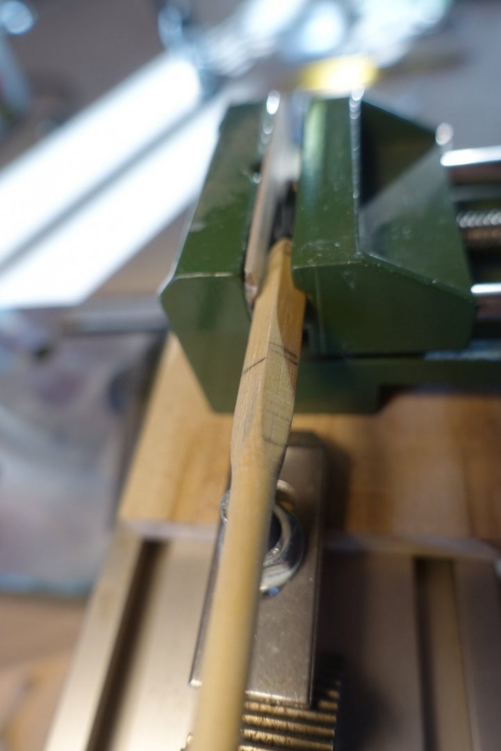
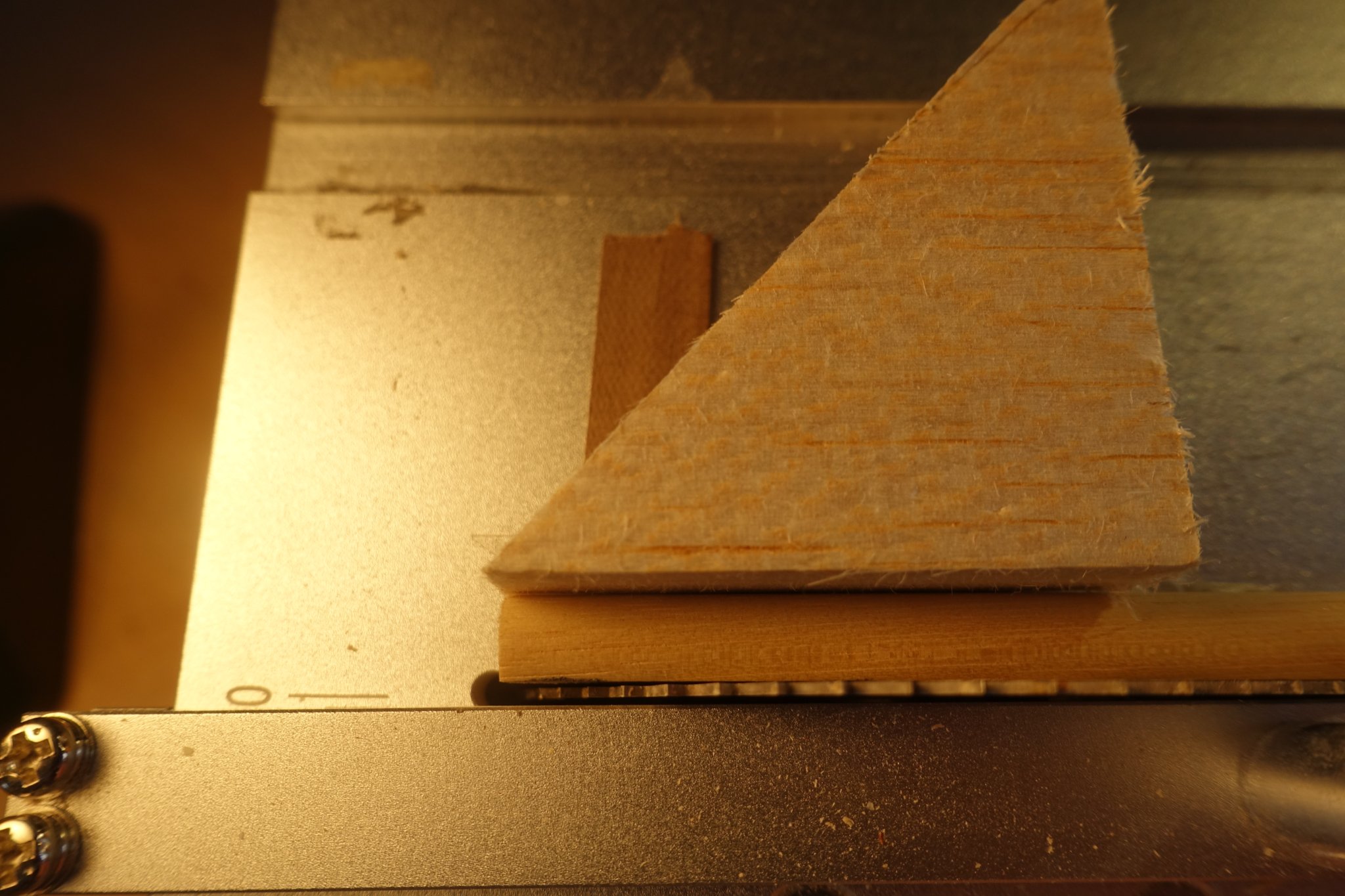
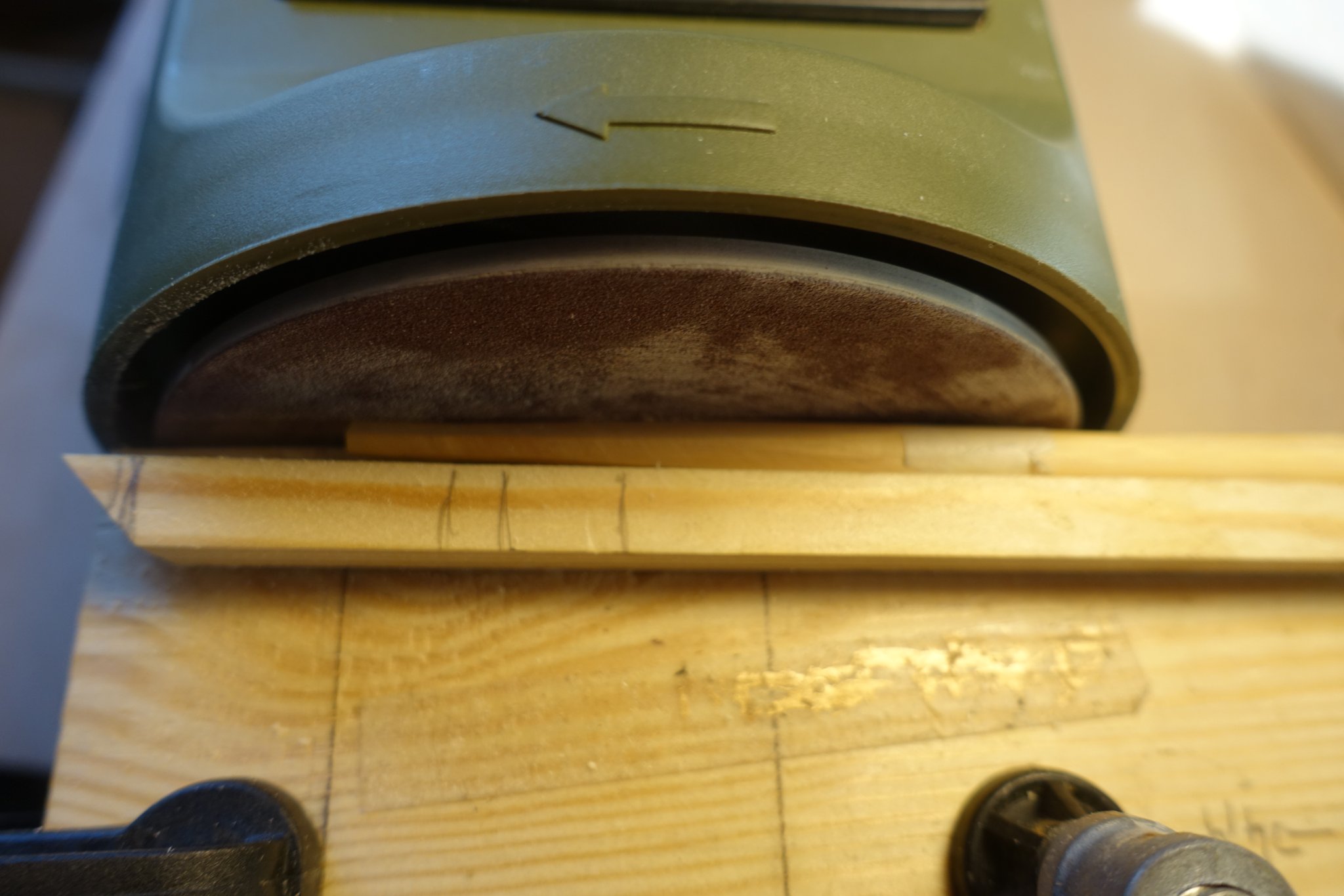
I have started preparing the foremast. As always this takes sone time. Progress is not immediately visible.
Upper end of the mast is quadratic. I used the table saw to get it in shape. After making it quadratic I bevelled the mast using the “lathe” described above. Lower end of the mast has to be shaped octogonal and bevelled. I glued a wooden trim on a base with 3° deviation to form a guide bar and adjusted it to a disc sander. To get the mast rotated by 45° and in agreement with the quadratic end, I fixed the quadratic end of the mast in a small vice.


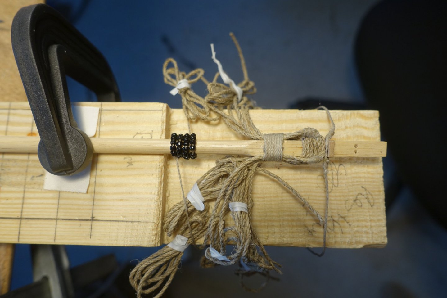
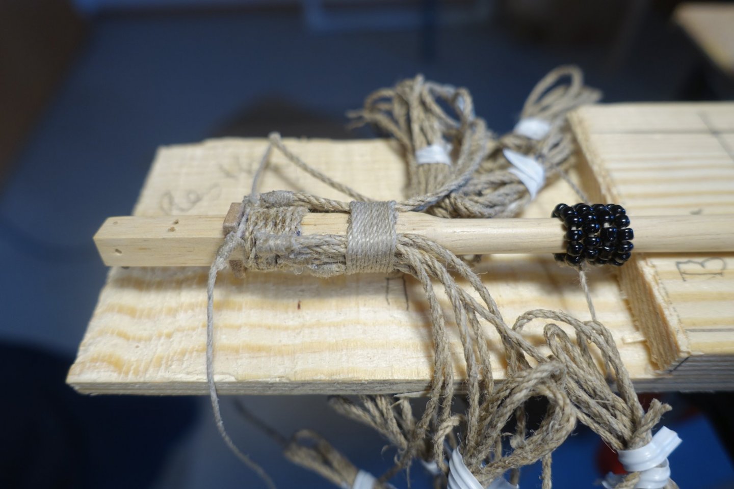
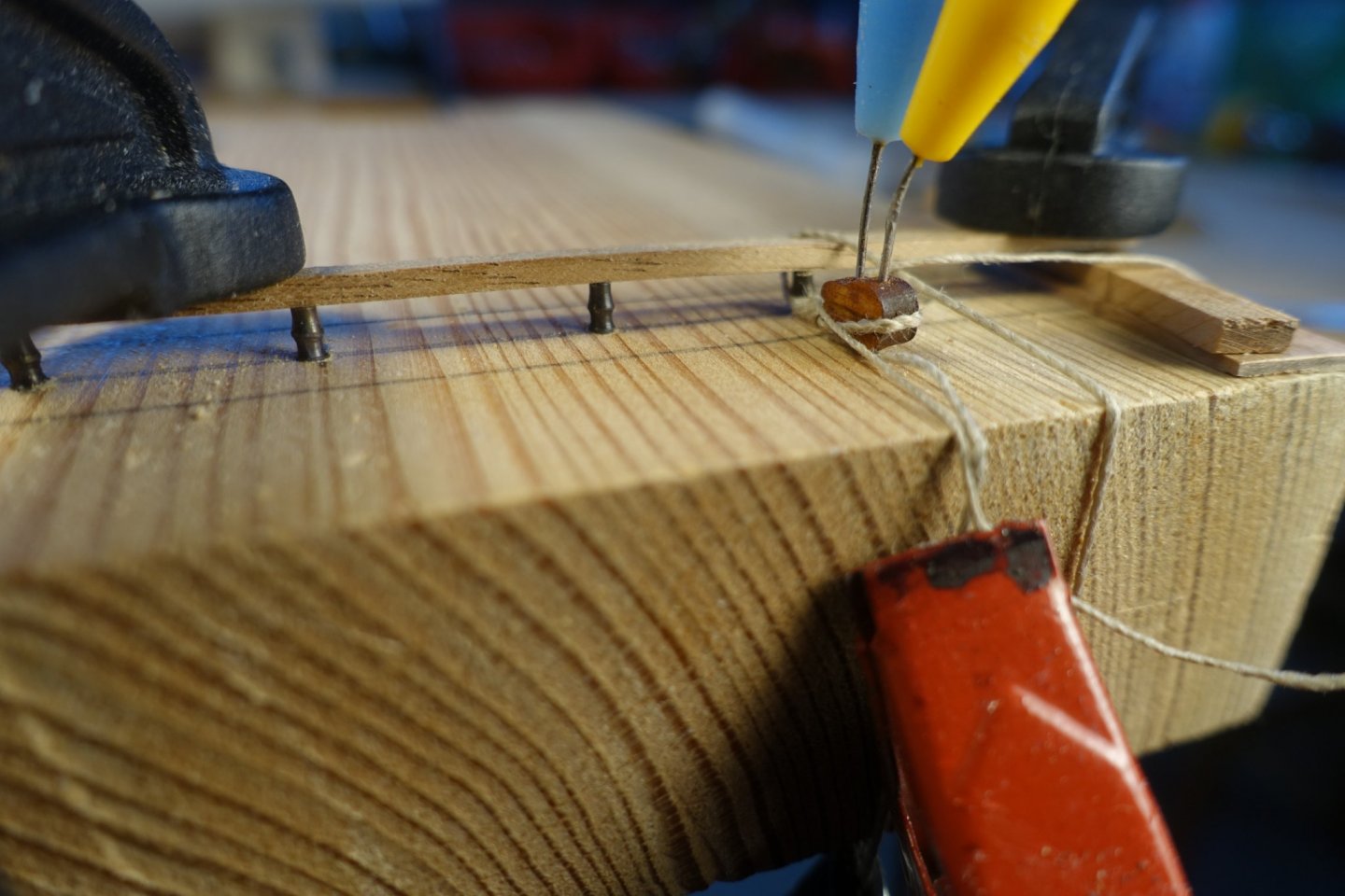
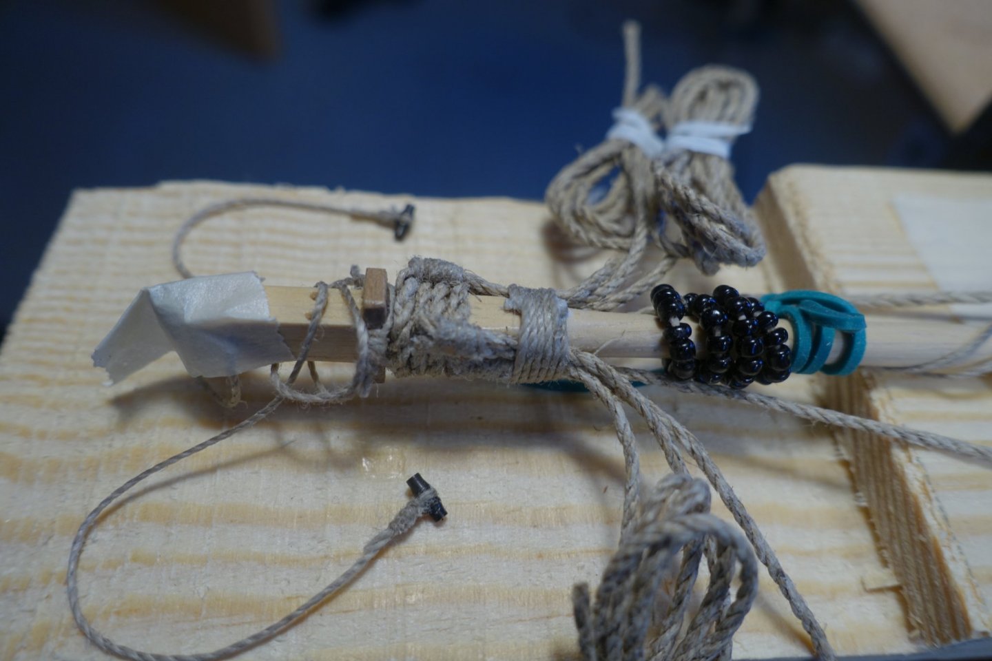
Before adjusting the masts, I prepared all the lines of shrouds and back stays. I found it difficult to fix the toggles. Thus, I drilled holes with smaller diameter than the middle of the toggles to put ~1/3 of the toggles in it. Upper end of the toggles end was fixed by a trim. It made handling of the toggles much easier. All lines were pulled through bee wax. Racks were also added before gluing the masts in place at this stage.


- Gimo, GrandpaPhil, 72Nova and 1 other
-
4


Reale de France by Clark – FINISHED - Corel - Scale 1:64
in - Kit build logs for subjects built from 1501 - 1750
Posted
Thanks for stopping by.