


Clark
-
Posts
238 -
Joined
-
Last visited
Content Type
Profiles
Forums
Gallery
Events
Posts posted by Clark
-
-
-
8 hours ago, fmodajr said:
Hi Clark,
I like the "slipway" stand you made!
Happy Holidays to you!
Frank
Thanks Frank,
I got the feeling that adjusting the keel in the vertical axis might be a bit difficult since it is not very high and thus may not have sufficient length to attach right angels. I noticed that you have constructed a very sophisticated apparatus ("overkill") probably due to the same thoughts. Hope you can enjoy the following days despite the tough year you had.
Clark
-
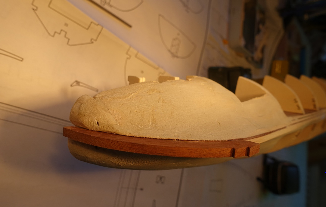
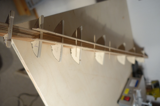
Keel is now roughly tapered. The first tapering seemed to be easier to me with no frames in the keel. Fine tuning will follow when frames are glued and sanded.
Keel was mounted into a slipway made of wood blocks and right angle metal winkles for later adjusting the frames in the correct position. Frame and keel slots were slightly sanded in that the deck lines of the frames touched the outer lines of the triple frame with no difference in height. It came out that the frames delivered by corel are quite correct. Only minor sanding was necessary.
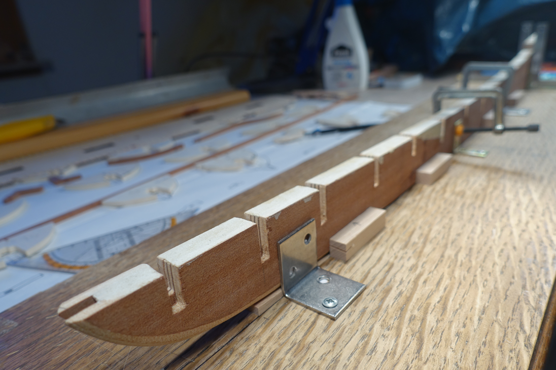
After gluing the frames, deck lines of the frames were again corrected/sanded. Deck line was controlled by attaching strips. Hull side of the frames were roughly sanded after attaching strips and looking to their slope. In two frames, strips 0,5x5mm had to be glued on one side since they did not get in contact with the strip attached. These frames were sanded again. All in all it was a permanent interplay between controlling, measuring and sanding, everybody knows.
Filler blocks and wood filler are now added to the first two bow gaps and the last two gaps at the stern. Sanding and controlling the hull line at the bow and the stern again and again. I got the feeling that this sanding and filling procedure is easier without the deck and deck planking attached.
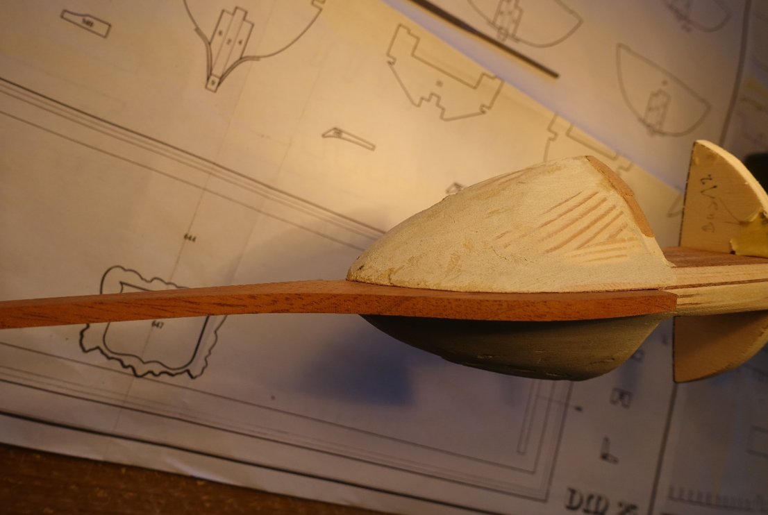
There is a good description of producing filler blocks in the forum (http://modelshipworldforum.com/ship-model-framing-and-planking-articles.php…). In contrast to the descriptions mentioned I dry measured size and shape of the filler blocks directly in the ship without making templates. I trust on eyeballing.
Ship is now put backwards due to Christmas. Some of children and grandchildren are coming and we are also visiting those living a bit far away.
- GrandpaPhil, stuglo, J11 and 4 others
-
 7
7
-
-
Hi Frank, I am not as experienced as Hubac s Historian. But just on logical grounds: I would draw the ropes for the middle carriage the other way around the wheels: outside in. At present the ropes get in close contact with the carriage wich would damage them (when the ship would really be in fight).
Clark
-
21 hours ago, Hubac's Historian said:
Hi Clark,
This image came from my Pinterest page, French Vaisseaux.
When I clicked the embedded link, it just took me to a blank page. All I have for you is the partial web address you see in the screen capture, above.
However, if you visit my Pinterest page, you will find nearly 900 images of French ships from the 17th and 18th century; portraits, models, etc. As far as I know, it is the most extensive database of related imagery on the web.
Check it out - there’s other Galley stuff in there, as well.
Found it, perfect! Clark
-
Al, Thanks for visiting.
-
Thanks Gimo, where is your Reale now?
Clark
-
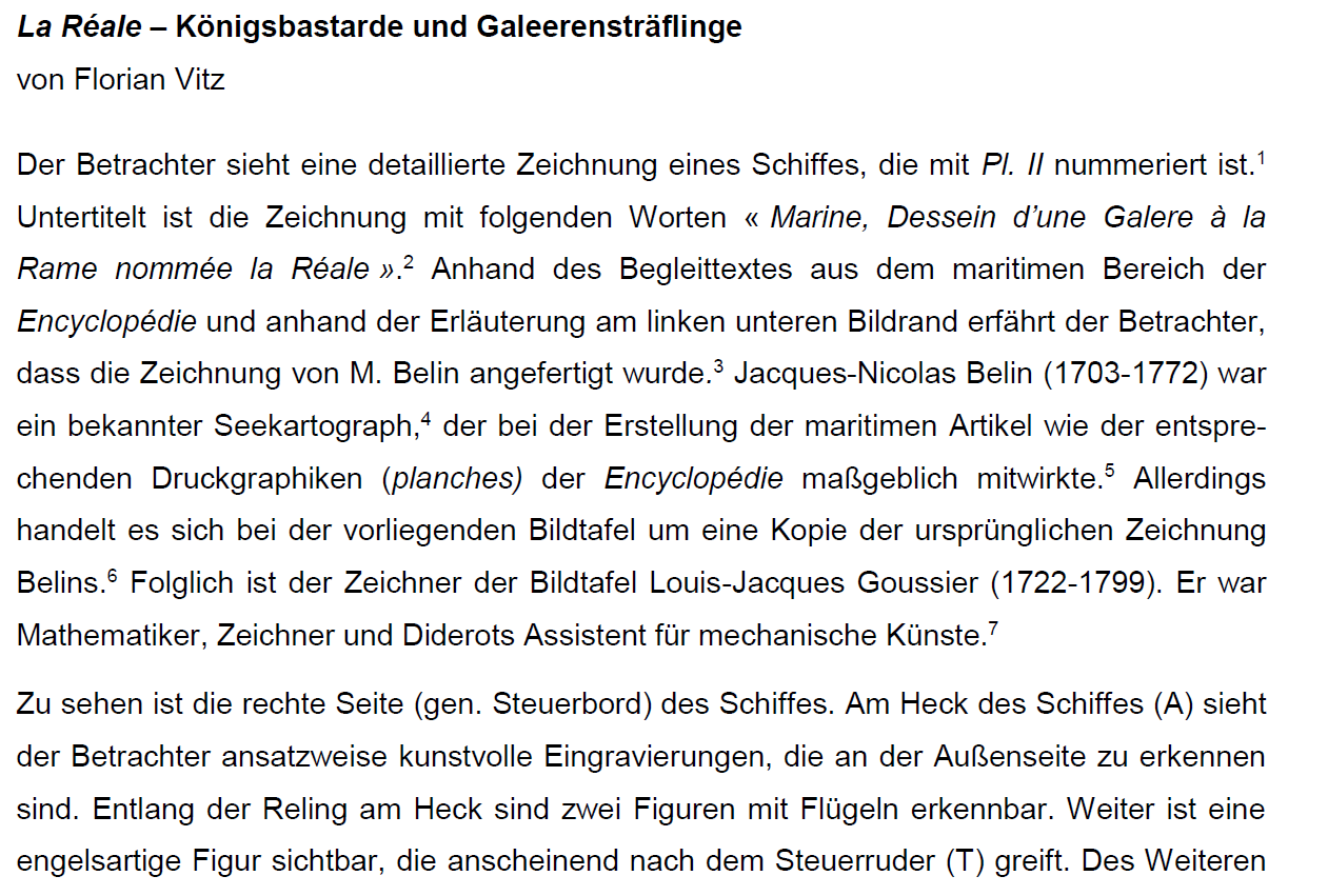
Hi Frank and Hubac's Historian,
thanks a lot for helping me. The painting is really helpful in building the ship but unfortunately it is probably not the one described by Vitz. It can be read that the starboard side is shown and not the portside. Moreover it is probably a drawing and not a painting. Meanwhile I figured out the the text copied is part of a thesis written at the Universtity of Duesseldorf (near the river Rhine, near France??). I will try to get in contact with the University to figure out the sources.
Can you send me the link, where the painting of the Paris Museum can be looked at? There is no accdess via the website of the museum at least the way I tried.
Thanks a lot
Clark
-
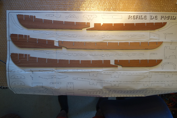
I am going to join the club of modelers constructing or having constructed the ship. Frankly speaking, their construction and kit reports (gimo, Bender, fmodair, schiffebastler) urged me to order the kit. Mainly the very sophisticated report of Frank (fmodair) increased my wish to build the ship.
I do not have the skills of the others mentioned. Thus this blog is mainly to those who rely on the material provided by Corel. Content of the kit is well described in construction reports of the club members.
Most of the material seems to be of good quality but I am already wondering how to amend the plywood pieces. As mentioned I will probably manly rely on the material provided by Corel. However I like to see the wood structure of the models implying that I will use color paint very rarely. We will see.
It seems to me that although Corel put some efforts in the written instruction manual, there is still enough space for improving.
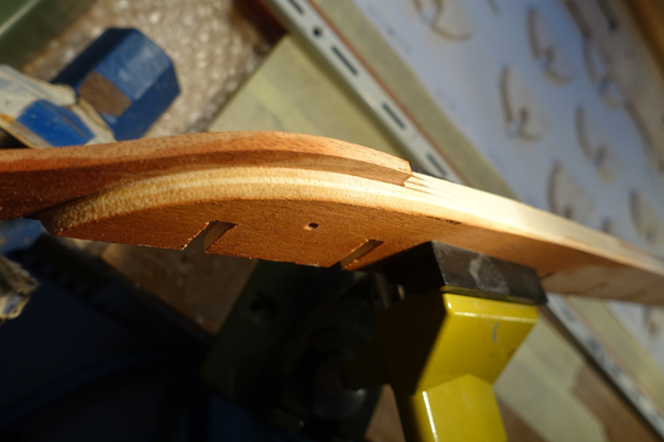
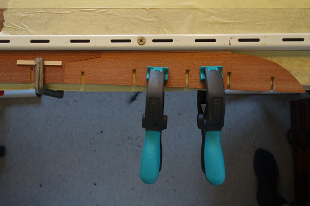
False keel is a triple one and made of six pieces which have to be glued overlapping to produce a keel three layers thick.
To keep the keel straight I fixed and clipped the parts of the keel flatly on a shell with a metal rail below the keel pieces. Since the lower line of the keel is deflecting, small wood wedges were put under the bow and stern side of the keel to get the distance from the metal rail (arrow).
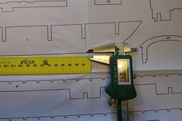
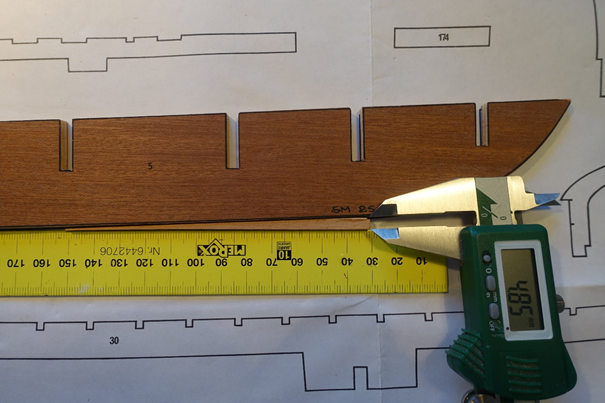
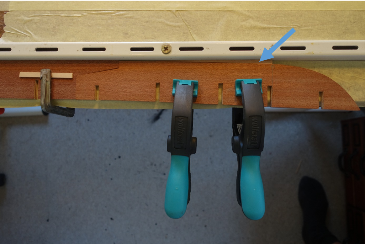
The get the three overlaying pieces in the correct position, small wood stripes 4x4 mm were put into the spaces for the frames/bulkheads. After gluing the keel, frames were dry (!) fitted by filing the slots of the keel and filing the slots of the frames. Bottom side and deck side of the keel was treated with wood filler and sanded.
Frames, false deck, the pieces of the true keel and other supports were dry fitted. Some minor sanding had to be done for this.
Next step will be tapering the keel and adusting the frames.

- JayCub, J11, KARAVOKIRIS and 4 others
-
7
-
-
-
5 hours ago, fmodajr said:
Clark,
Thank you for your comments. It is appreciated. I agree. I just have to decide how I want the ship (model) to be presented!
Michael,
As always, thank you for your input and research. Everything you stated makes sense to me
")
I will continue to use the monograph of "La Fleur de Lis" as a guide and the beautiful model by R. Courgeon, as I have been trying to do where applicable.
Thanks to all for visiting.
Frank
Frank, via Google I found an article of "Florian Vitz" describing a picture/painting of La Reale (in German) with a lot of details but not the cannons. Do you know what/where the picture/painting can be found? It might help with the cannon question.
Clark
-
Frank, it looks perfect. But I am still wondering if the carriages have to be secured differently (as in other ships) depending on the status of the ship: in fight or on trip. (Do not know if thats the correct english expression, hope you know what I mean.) Thus you may have to decide how you want to present your ship later on.
Clark
-
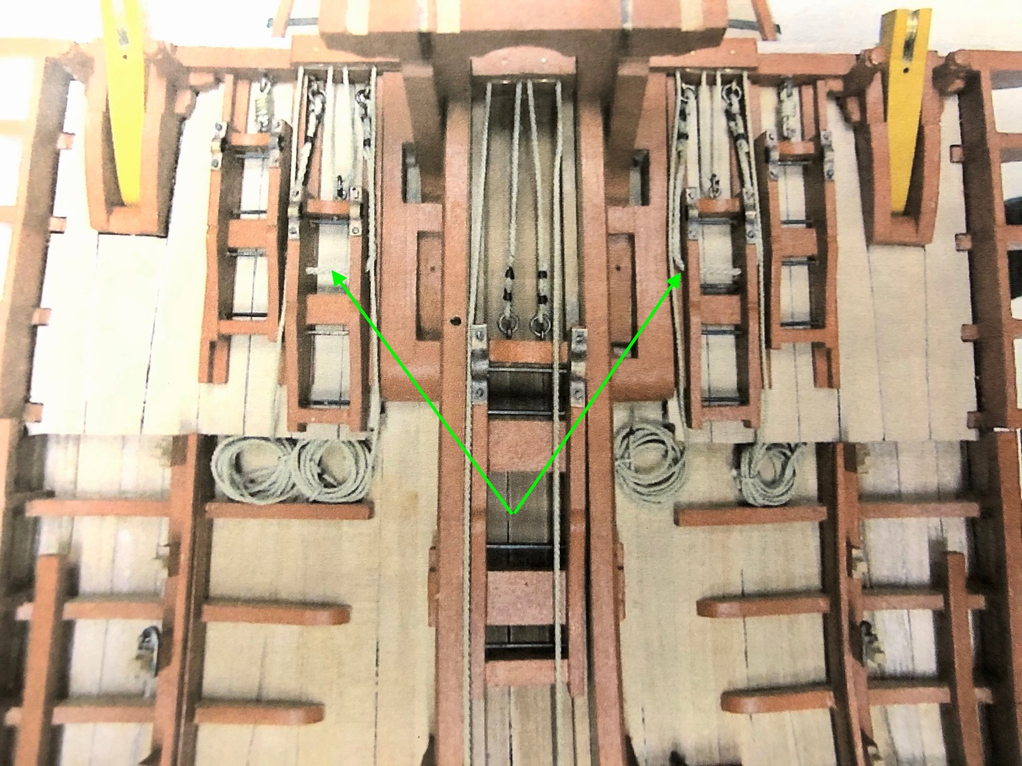
42 minutes ago, fmodajr said:
Hello Phil,
Thank you for all the assistance.
I don't believe the carriages were mounted in place, (but not sure)
I found this photo of a "Fleur de Lis" beautiful model by R. Courgeon which shows the abutting carriages with breach ropes. (See green arrows)
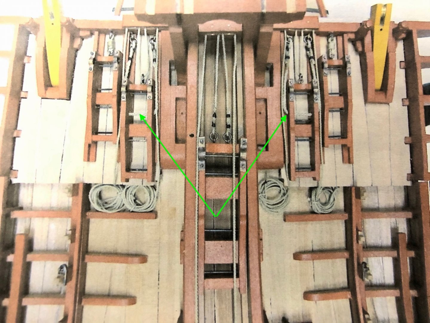
It also shows that the 2 smallest carriages at each end were just fastened to the front horizontal wood beam.
Anyway, with the carriages so tight next to each other, i'm wondering if the cannon balls were loaded from the front deck!!
Thanks again,
Frank
There is still the question where the cannon balls and the gun powder were stored when loaded from the front deck. I am also wondering how the carriages and canons were handled when they were such tight to each other.
Clark
-
I am not sure but just for logic: Is there also a rig needed to pull the canon back?
Enjoying your report.
Clark
-
-
-
-
On 6/21/2019 at 7:34 AM, Thunder said:
Hi, I have noticed that you live in Germany but the plank bender you have shown is 230V. Just check before you buy as I assume you are 110V in Germany.
Thanks for all the replies. Regarding the voltage problem, we have 230 V in Germany. The one shown is 33 Euro. I ordered it. However, I am already facing the problem that the planks I am working with have to be bended in two directions. I will problably start with a longer test perid when the bender has been arrived.
Thanks again
-
10 hours ago, marktiedens said:
I also have that plank bender - most useful tool I have ever bought.
Mark
Thanks all for the hints and the tips. You convinced me to buy a plank bender. The one of Aeropicola is not available at least in Germany. Does anybody has ever tested the one shown in the picture? Clark

-
-
53 minutes ago, kriss1 said:
Another beginner chiming in! I've been using the cheap Amati plank bender (like Sea Hoss), it works very well.
Make sure the iron is hot, then just dip the strips in water for a second (I've found no need to soak the strips for any period of time). I edge bend the strips with the iron and some clamps before using the wooden-form to curve them, found that to give better results.
I tried using the manual bending tool before buying the electric one, but found that to be too annoying, frustrating and slow to be of any use.
Dear all,
does anybody have experience with soaking the strips for some minutes in hot water (~80°C) and bending them directly therafter by fixing on right plyce of the hull? I read it somewhere in the forum. One simple problem for me: One end (stern) maybe easily soaked, but whats about soaking and heating the other end (bow) when the strip is fixed on the hull. It may be a silly question but I did not got a solution so far.
Clark
-
1 hour ago, vaddoc said:
Just to add my experience, I bought the little proxxon table saw KS230. The only thing I ask is straight cuts in thin wood material and I think this is the only service it can provide. I have our old decommissioned vacuum permanently attached to it. For any other task a much better, bigger and ultimately very different saw would be needed.
This saw should provide the same service and really it is pretty cheap. Hopefully it will prove reliable, accurate and user friendly. Please Clark keep us posted
One more thing to consider is safety. The little Proxxon is very underpowered which is good, as I found that table saws can be very dangerous. I have had a few kick backs and other incidents and the real safety feature I think is the lack of power. I now treat it with great respect, wear always eye protection etc. Maybe a better saw would be safer just by being better built.
Really everything must be very well aligned and rigid otherwise things fly off at supersonic speeds.
I also run into this, Proxxon rebranded very cheap saw. Maybe worth a look
Thanks for the many replies and comments.
Just to add my experience with the saw since I bought it several weeks ago:
I did a lot of cuts with various types of wood. I mainly used it for making wood filler between frames and for constructing supports in a slipway. Thus no work with the need to be very precise. There were no problems to do straight cuts with a precision of about 0.5 mm in wood pieces up to 20 mm thickness. The only problem I had was doing angular cuts with small wood pieces. I glued the pieces on longer sticks and fixed the miter gauge accordingly. It worked.
I would strongly agree that a saw is dangerous. The protection system of the NovelLife is not the best one. Moreover, it sometimes interferes with handling because you cannot hold the wood sufficiently when the protection system is mounted.
The speed of the saw can be varied by adjusting the power supply which is comfortable when handling different types of wood. But it probably makes no ´difference when cutting your finger with 12V or with 24V. I did not try it.
I would not use the saw for cutting strips for deck planking or hull planking.
Clark
- thibaultron, Canute and mtaylor
-
3
Reale De France by fmodajr - FINISHED - Corel - Scale 1:60
in - Kit build logs for subjects built from 1501 - 1750
Posted
Hi Frank, Hi Hubac;
meanwhile I received an answer from the University of Duisburg (not Düsseldorf). It describes a picture of Encyclopédie of Diderot and d'Alembert. Is this the same you took your pinterest photo from? Frank, do you have the book of Mondfeld (picture)? There are plans inside form which you can delineate the size of cannons. Clark