


Clark
-
Posts
238 -
Joined
-
Last visited
Content Type
Profiles
Forums
Gallery
Events
Posts posted by Clark
-
-
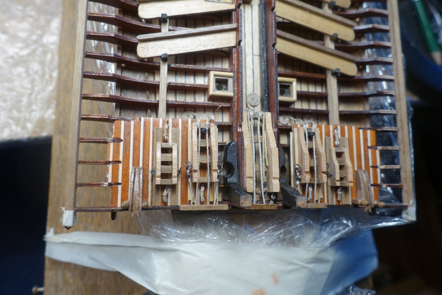
The outer platform is now glued. I had a discussion with Frank some time ago about the holes in the platform. He drew my attention to the fact that the shroud chains are led through the holes. Shroud chains contacting wood are probably not doing well on the long run. Thus, I simulated an enforcement of the holes.
The outmost fixation of the outer platform is covered by a small brown/white strip 1mm thick and a walnut strip on the top. I put small “pyramids” on the stern and bow ends to cover the different types of wood.
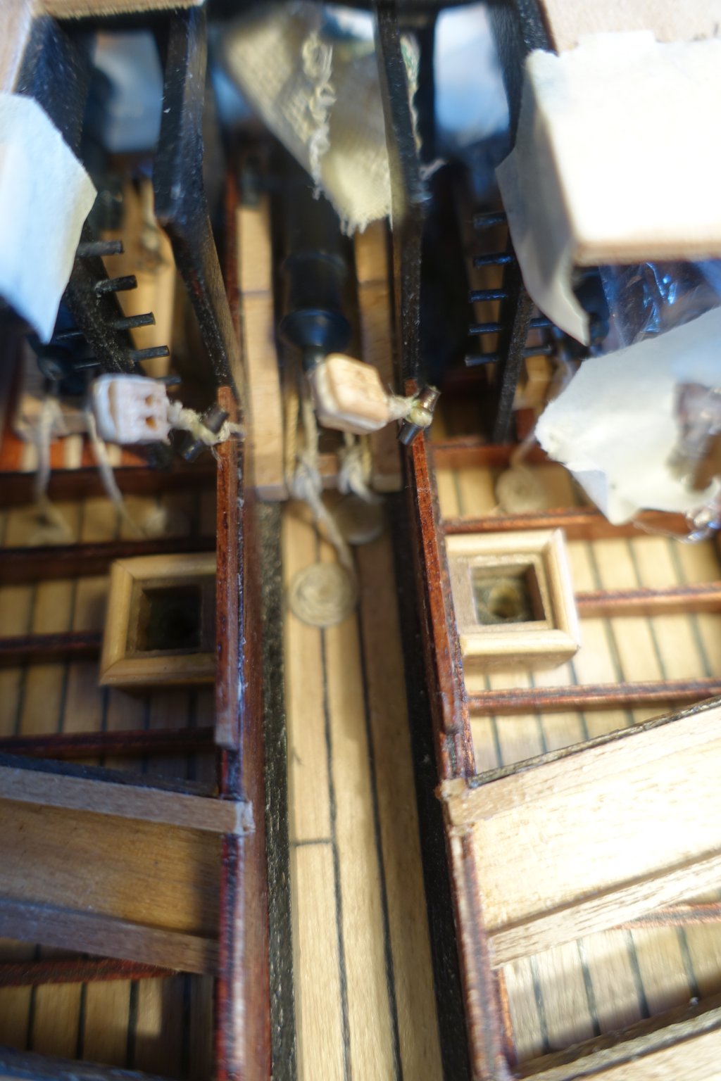
In the corel plans there is a suggestion to fix the blocks for slackening the fore lateen yard in the middle near the main cannon. This would not work since it would hinder managing the main cannon. Thus, I fixed it behind the main cannon.

-
-
Hi Udo,
glad to see that everthing was o.k. Via CAF Ad, I also got notice of the kit which seems to be very sophisticated. However, I was a bit puzzled by the CAF Webite which looked a bit semiprofessional. Nevertheless, the coureur is on my list. I am eager to read your report and critics.
Clark
-
You will enjoy it
- mtaylor, Canute and thibaultron
-
 3
3
-
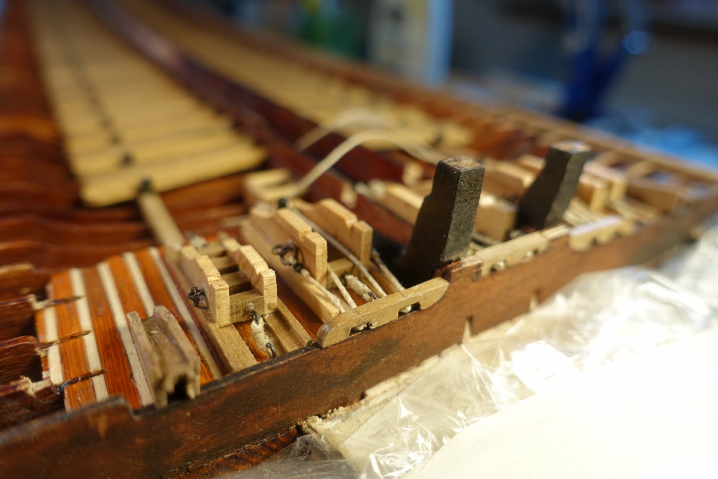
Regarding the gun deck, I had to regard some points. First, I want to show the ship on trip and not in battle. Thus, the carriages have to be tightly fixed and everything has to be cleaned up. Unfortunately, I could not find a plan how to fix the carriages. Frank (fmodair) shows one in his blog from the fleur de Lis but I am not sure if the fixation shown really worked when the ship was on trip. I created a solution of how I would fix them if I were the 1st officer or anybody else responsible.
- GrandpaPhil and fmodajr
-
2
-
Congrats. Did you even keep the music in mind (radio on the shelf?). Like Nils I am also wondering about heating, which might be a more severe problem in Germany despite climate change.
Clark
- thibaultron, Canute and mtaylor
-
3
-
Frank, looks great (as expected). Regarding the center decking planks: I have browsed through the plans and have noticed that some rigging runs through the midway. Thus I decided to make the center planks immediately before starting the rigging when all the other stuff is mounted. Do you have any idea how to handle the rigging, when the midway is coverd by planks?
Clark
-
The footboards had to be glued overlapping on the benches. To get a 1mm overlapping, I made a small rectangle with 1 mm strip on it. Hope the pictures explains
 it.
it. - GrandpaPhil and fmodajr
-
2
-
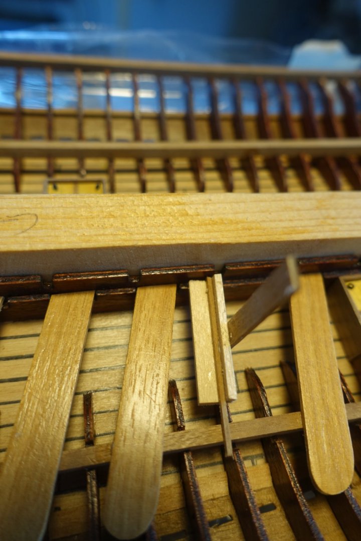
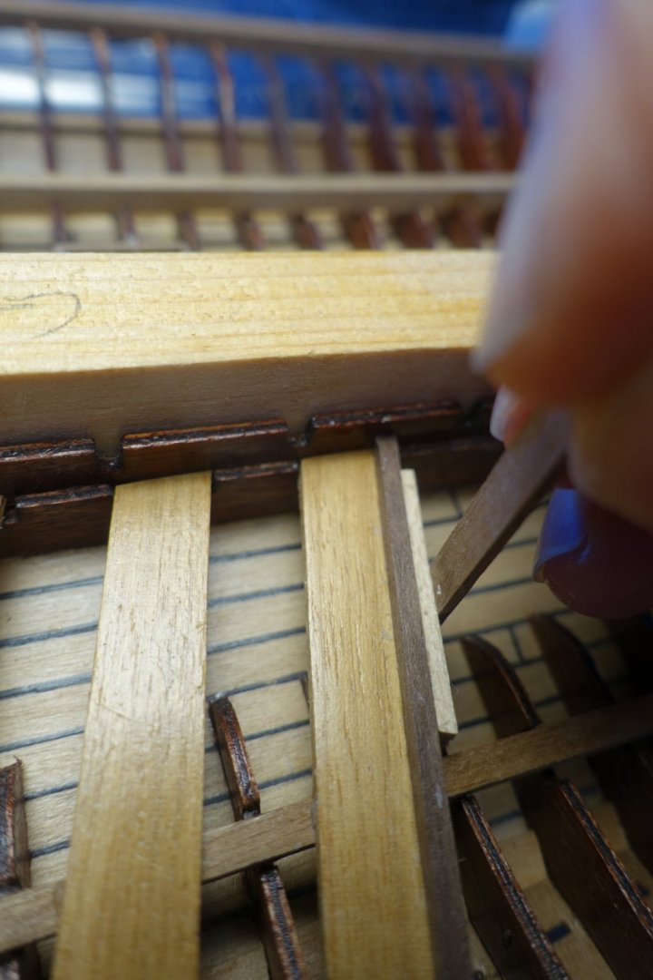
To arrange the benches, I wanted to use the template of the outer platform (named arbalester base by corel). However, the plywood pieces were very slovenly cut by corel. Thus I had to put some effort in sanding them or extending by gluing additional wood strips. May be it would have been much easier to make them new as Frank (fmodair) did. For arranging the benches in line with the outer platform I used a wood piece to keep the angle.
- GrandpaPhil and fmodajr
-
2
-
Frank, the advantage (at least to me) is that you are ahead. But I was also reflecting about the two holes for the foremast. I could also not realize why there are two. Following the Fluer de Lis may be an option. But it also may have been a sense of symmetry since it was a ship of pomp.
Clark
-
-
Thanks Frank,
the photo and my description my have led to errors but I have just drilled the water outlets, the slots for the shrouds are probably led through holes in the outer gangway. I will keep your hint in mind.
Clark
-
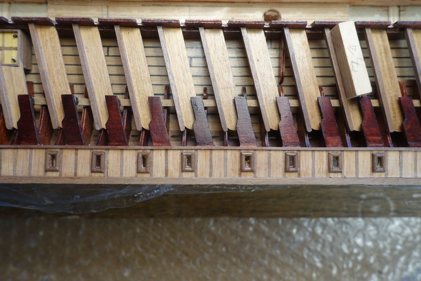
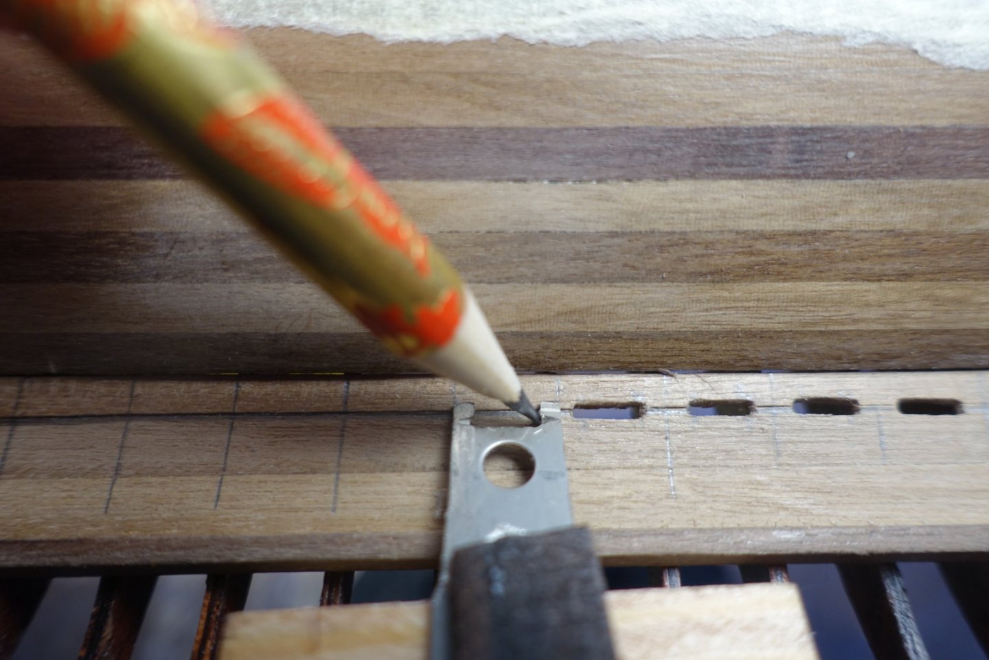
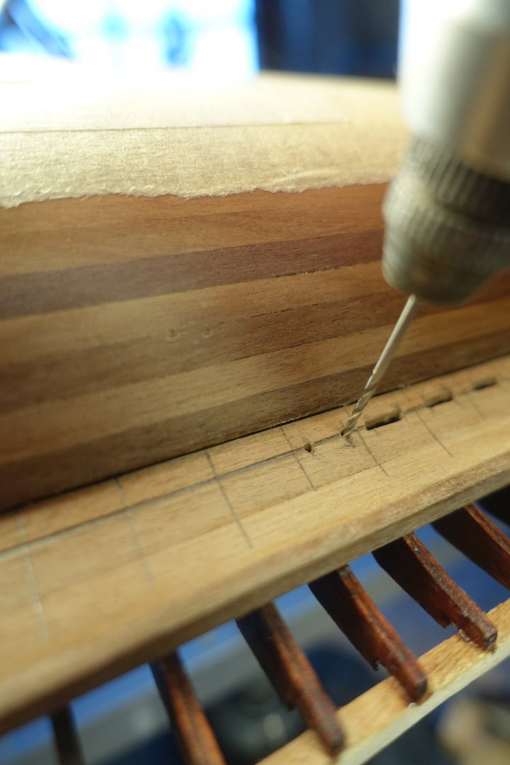
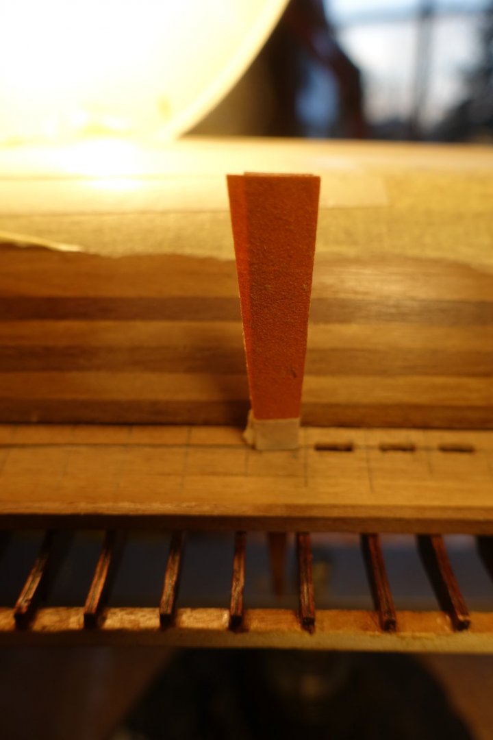
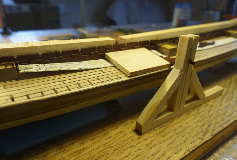
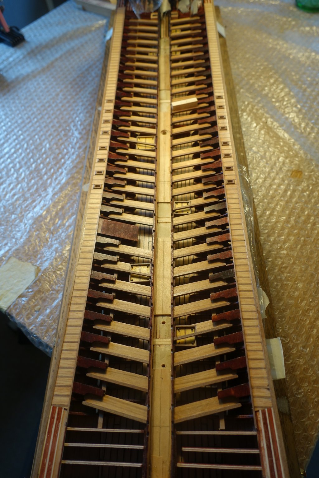
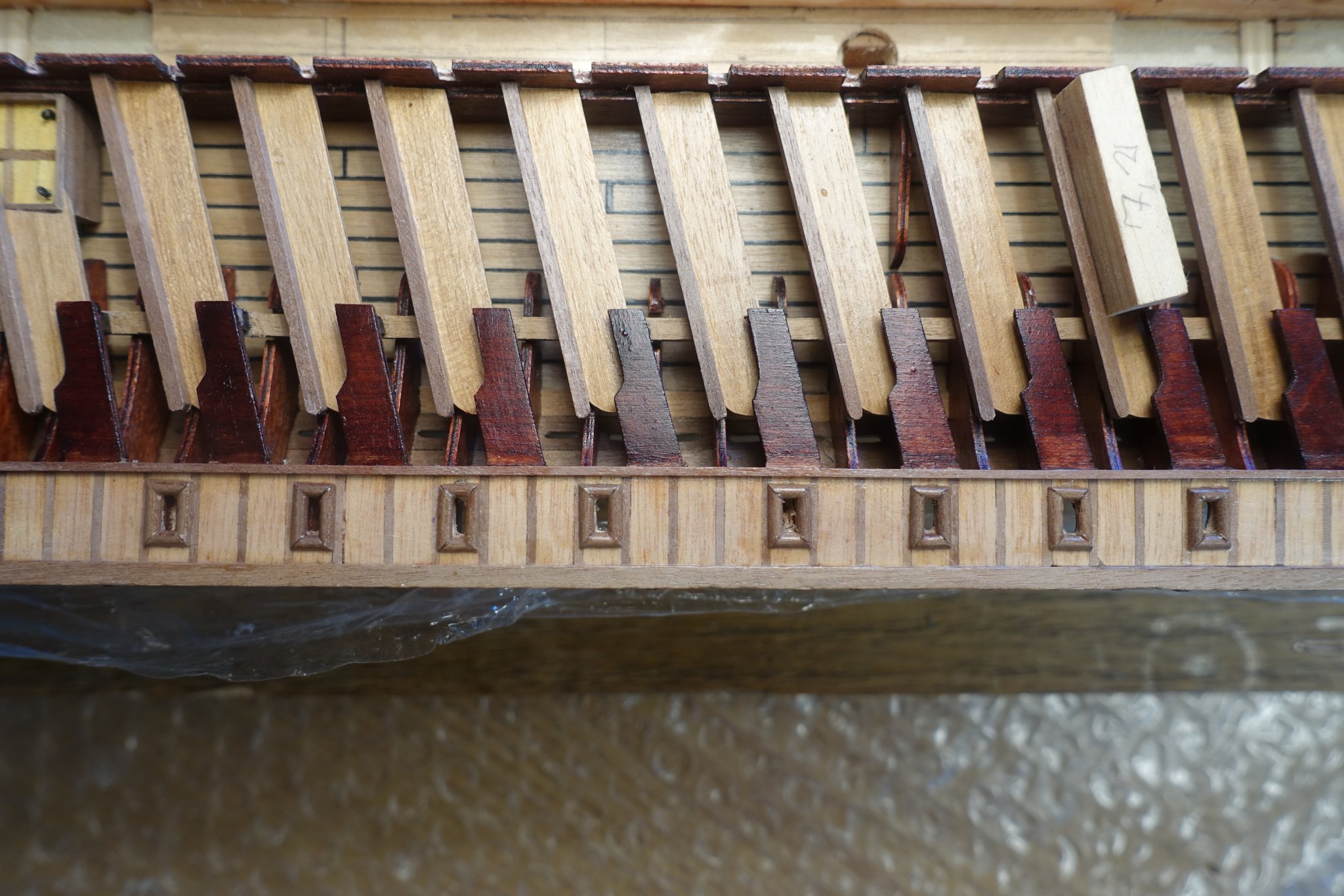
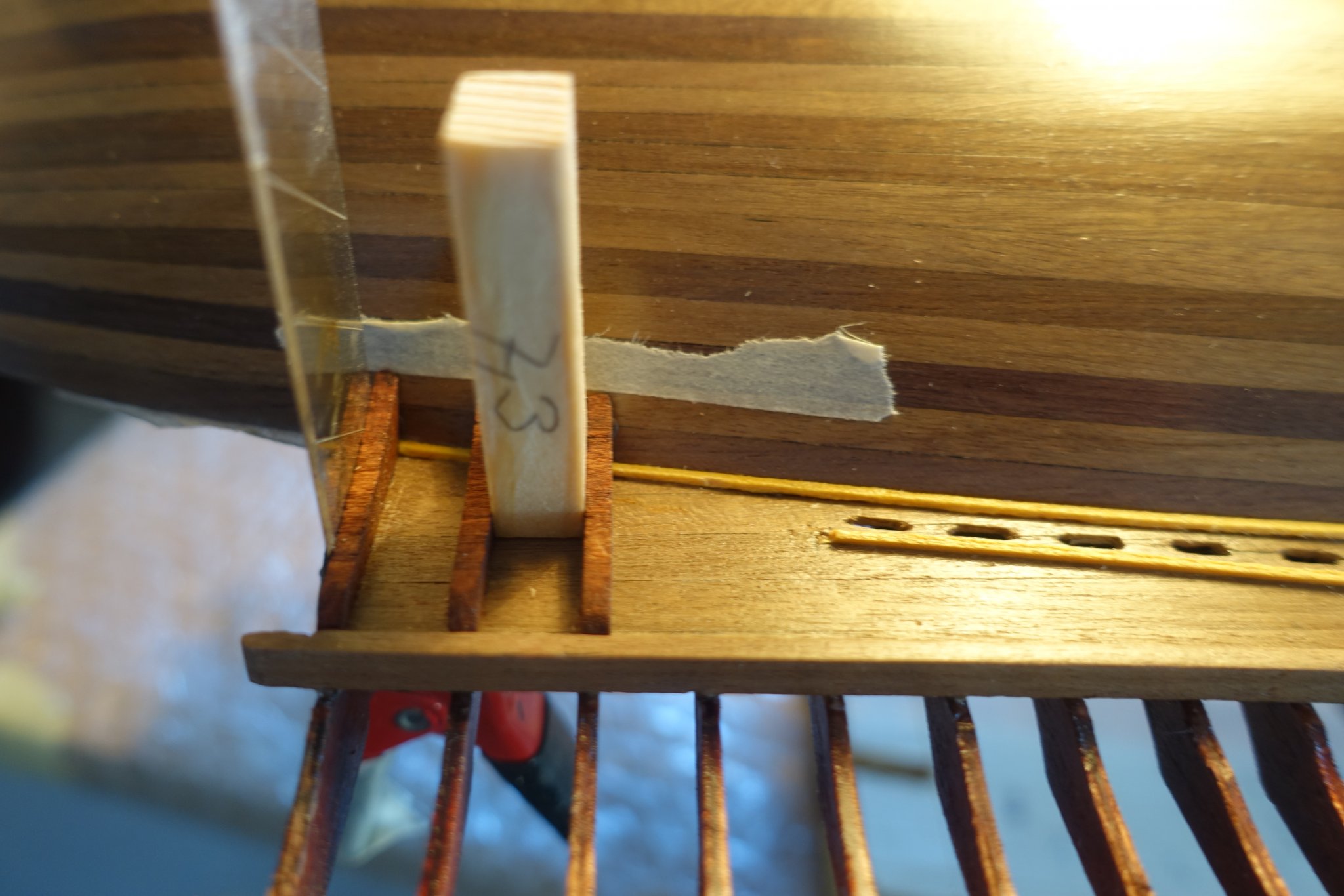
Lower planks are glued now and I have started to drill the holes for water outlet. I made some help lines. One line 3 mm distance to the hull to mark the middle of the holes. Rectangular ones to mark the location of the supports. Distance between the rectangular lines was 9.5 mm. Thus, I made a small metal template, outer width 9.5 mm with an inner opening of 6 mm to mark the limits of the holes. For drilling the holes, a driller 0.8 mm was used, wood between the holes was cut and sanded. 6 mm width was marked on the sander (sanding paper glued on wood piece).
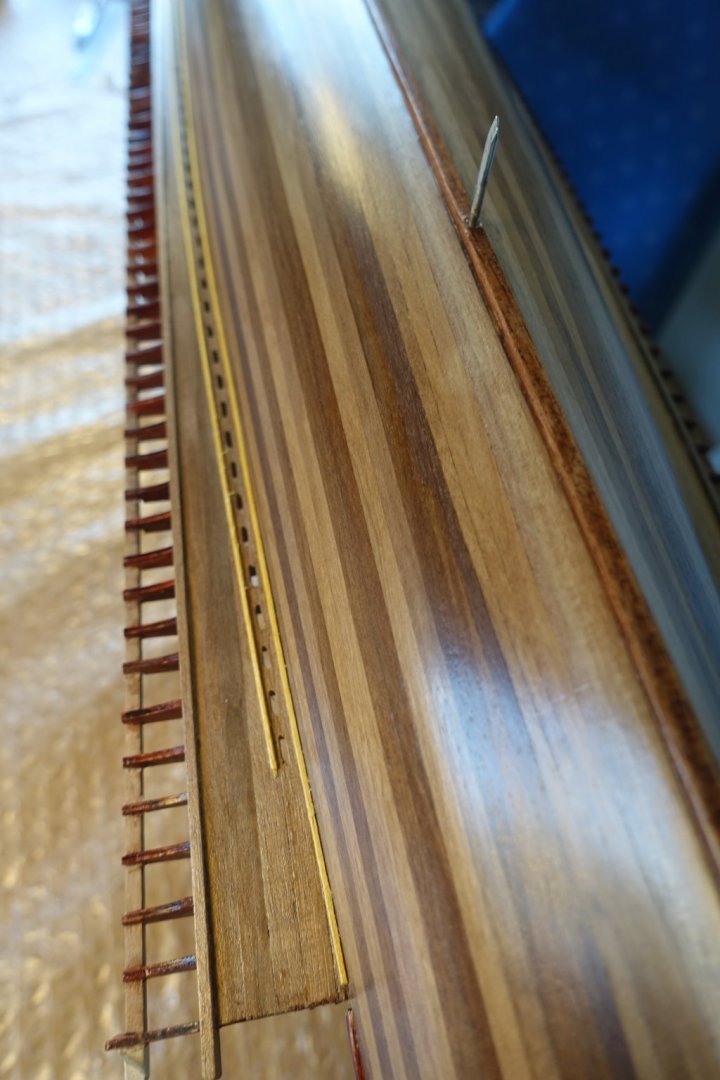
To arrange supports for the lower planks, I started with the first one arranged by a metal strip clamped to the yolks. Gap between the following supports was kept by using a wood block with 7.3 mm thickness

- Gimo, fmodajr and GrandpaPhil
-
3
-
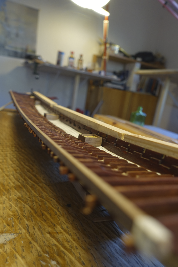
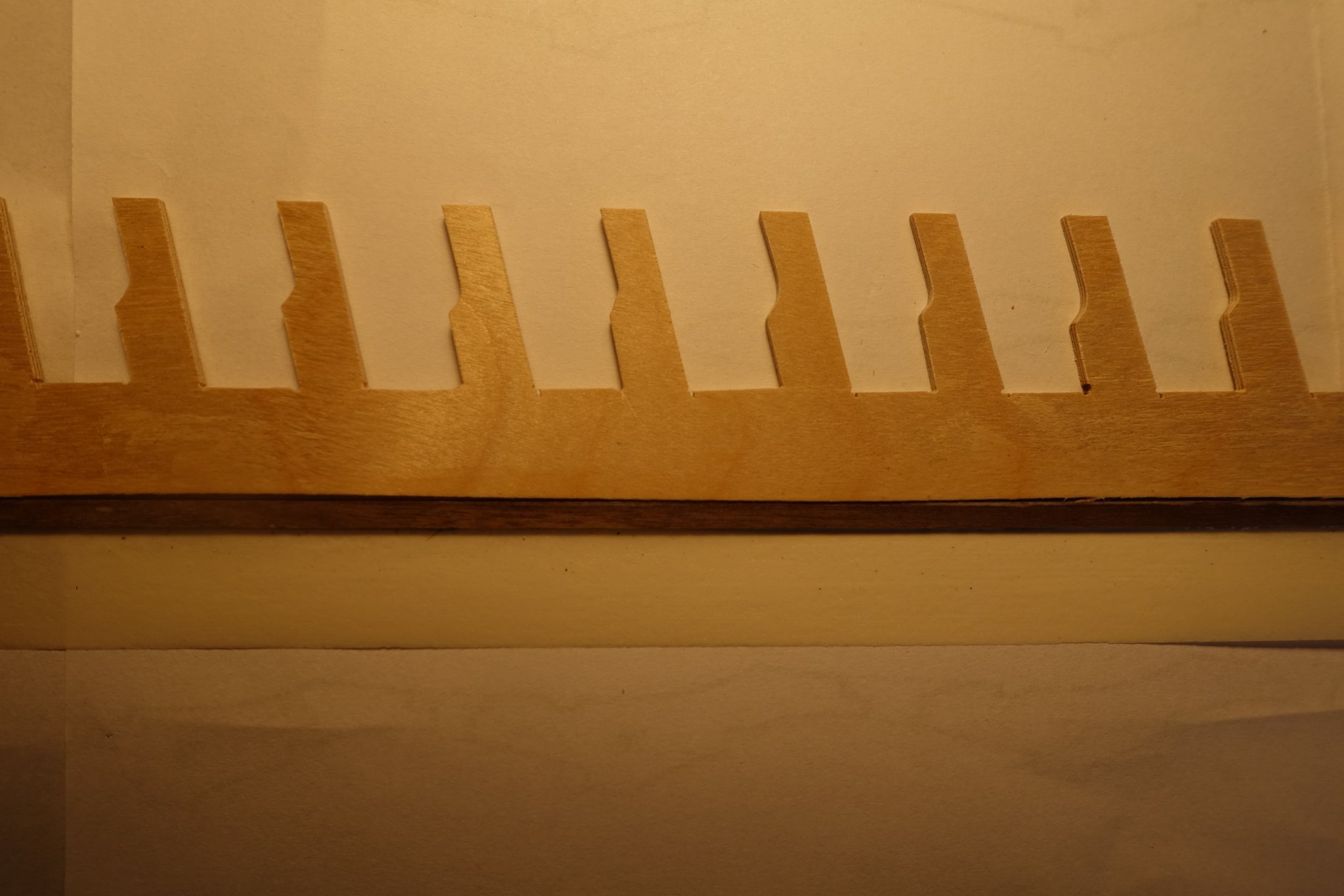
Supports of port side and starboard side are now all fixed. Outer ends of supports had to be corrected in height.

- GrandpaPhil and fmodajr
-
2
-
-
Frank,
it is a pleasure to see your progress and the effort you are putting into the details. I noticed that you did not install the cannons yet. This because you wanted to finish the front deck first?
Clark
-
20 hours ago, fmodajr said:
Only one side left to do! Lol!
From the first photo, it looks like you got the curve of the supports perfectly.
Nice job Clark!
Frank
Thanks Frank, when I first read your blog I was astonished that only a limited number of supports can be adapted per day. Now I know what you meant.
Hope to read further inspiring news in your blog.
Clark
-
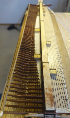
All supports of port side are now fixed. It really took some time.
- VTHokiEE, GrandpaPhil and fmodajr
-
3
-
With every new ship fun and effort in rigging increased. Doing the same knots again and again can be very relaxing after a hard day. When I began to build mediterrian ships, the task increased further since the plans and books showing the rigging are limited. Looking in the old paintings is sometimes not helpful. Comparing the rigging plans of Corel and Amatis Xebecs let me suppose that there is still a lot of variation possible.
Clark
-
On 5/16/2020 at 12:32 AM, Chuck Seiler said:
About the Wutender Hund. According to Chris Coyle, Wütender Hund was the vessel captained by Klaus Störtebeker, the leader of a group of North German privateers that were active at the end of the 14th century. Wütender Hund roughly translates to “Mad hound” or “Angry dog”. I will often refer to it as “Wonder Dog”.
If you look at various paintings and drawings of cogs, as well as more modern replicas, you will see some pretty plain cogs, some with stern castles and some with both fore-castles and stern castles. The very pronounce castle structures and “fighting top” show that WH was intended for fighting. Many had a raised stern castle for defense, while also providing a space to operate the ship, allowing more deck space for cargo.
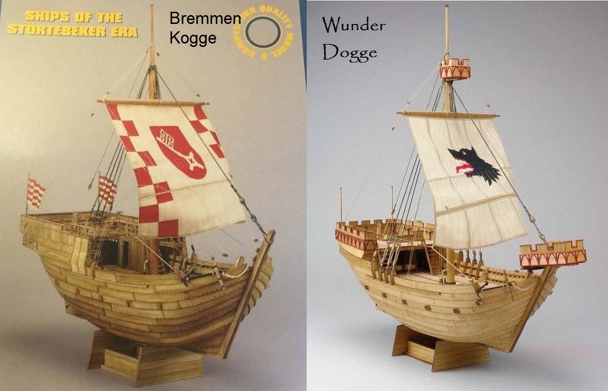
The two models (Bremen Kogge and Wutender Hund) show the difference between the trading cog and war cog. In these two SHIPYARD kits, the hull form is almost exactly alike, as are the parts. The hull form appears to be based on the same ship that inspired the Roland von Bremen, above.
The “trading cog” was often called into service as a “war cog”. I am not sure how easy it was to add or remove the stern castle, but the fore-castle appears to be easily added and removed.
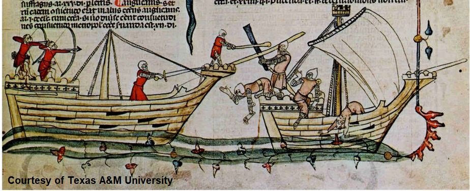
BATTLING COGS or THE FIELD TRIP DURING TH LAST NRG CONFERENCE...you make the call. This shows the value of the higher castles.
Hi Chuck
I was happy to find your blog. Klaus Störtebecker is still a hero in Germany at least at the coast line. As far as I know, the ship is originally named "Toller Hund" : "Toll" has two meanings: mad and great. Klaus Störtebecker was both.
Clark
- mtaylor, Chuck Seiler, Louie da fly and 1 other
-
4
-
-
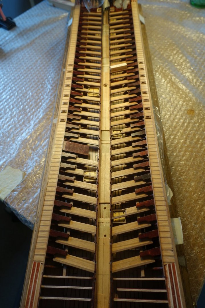
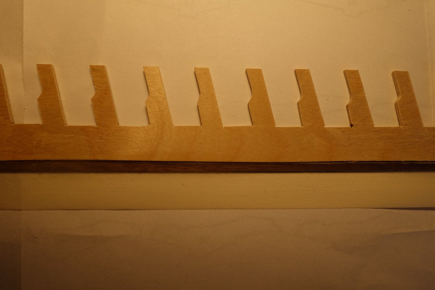
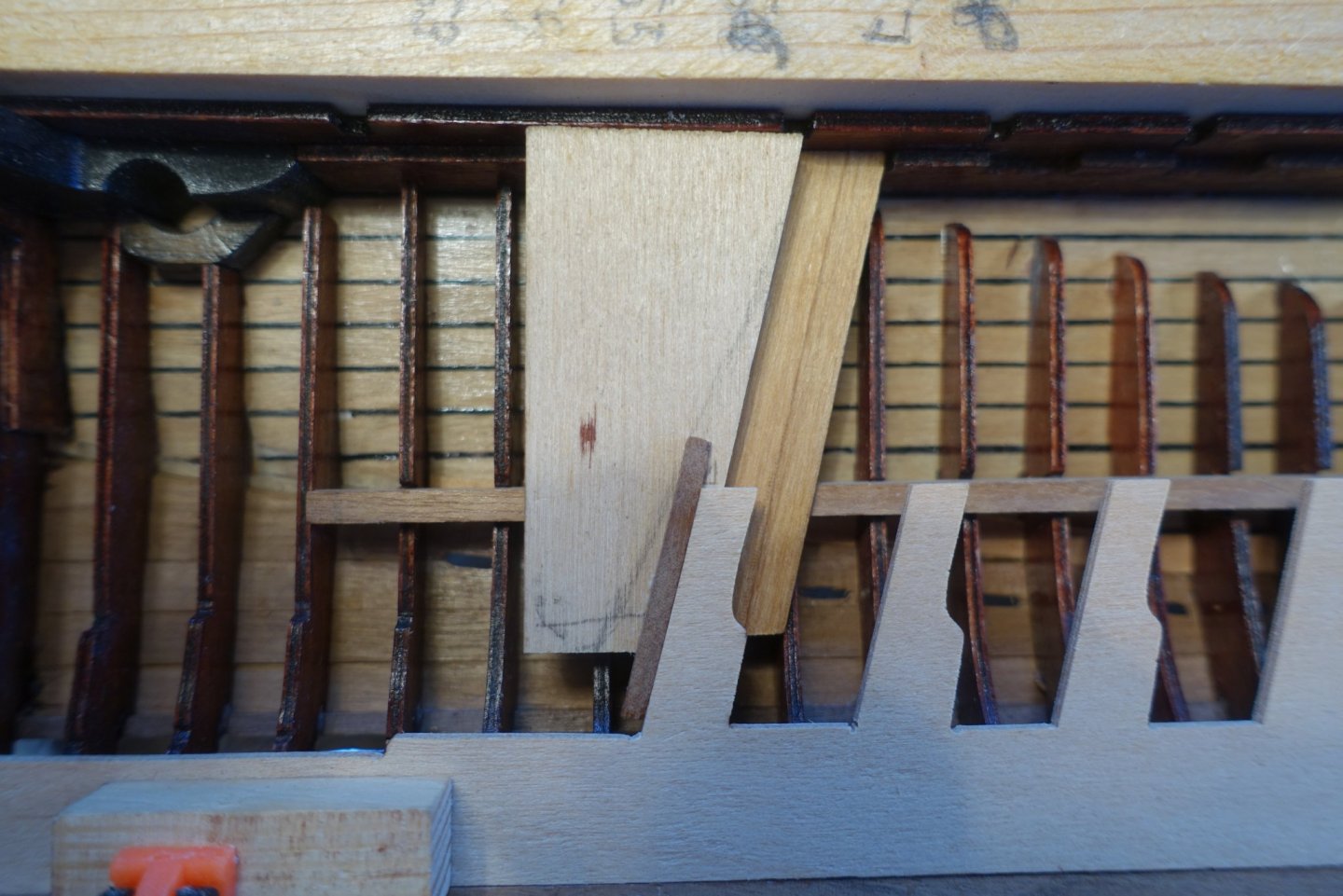
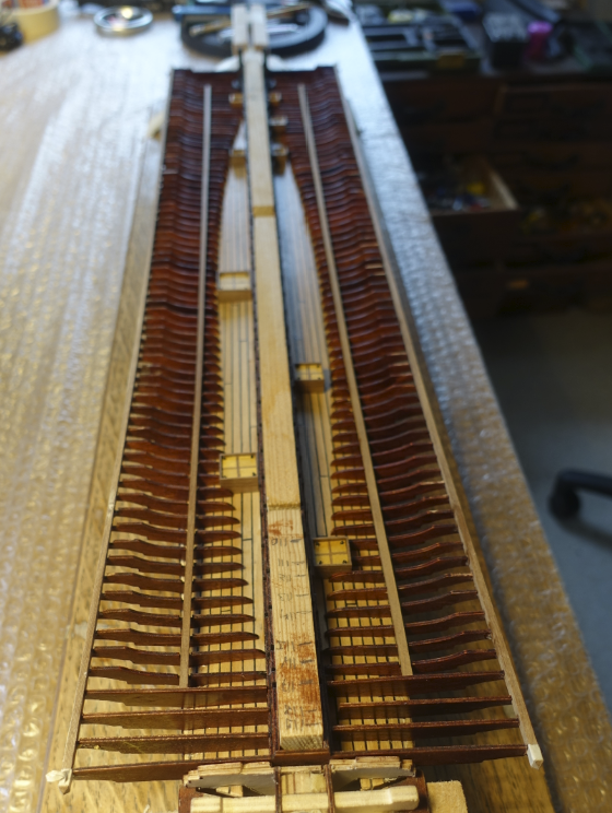
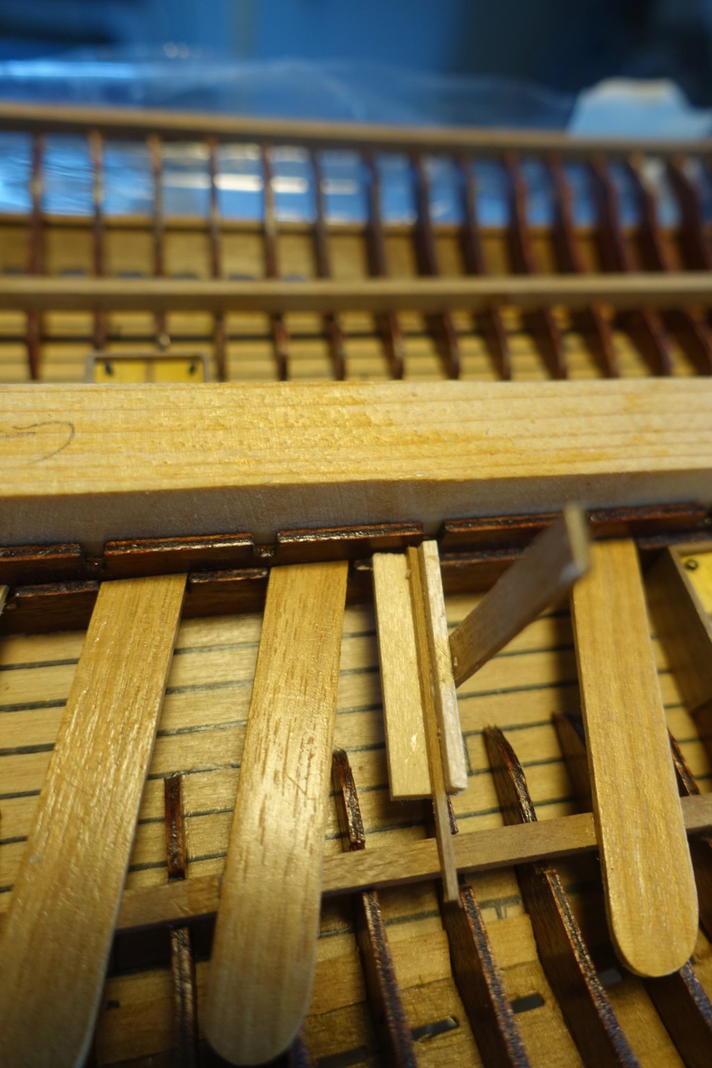
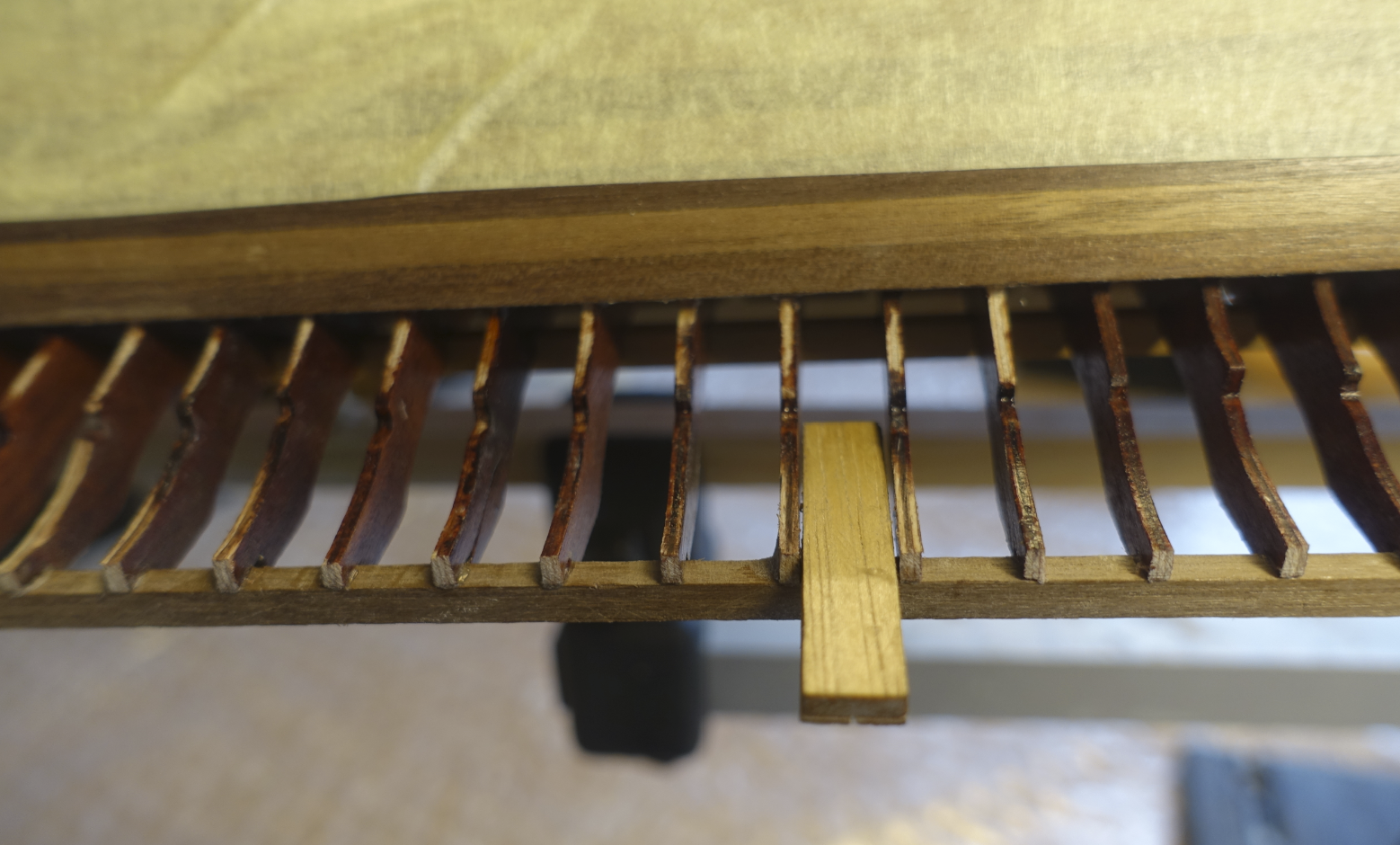
As suggested by the Corel manual, I started with the two middle supports #82 and #83 (Corel plans), which are at the lowest point of the deck line. To get them in a vertical position I made a holder with a 1.5 mm slot (= thickness of plywood) and 8 mm width of the vertical wood strips (= distance between the supports). I made also some wood pieces 8 mm wide to keep and control the distances between the supports. Additional supports were added between #82 and #83 and the yokes.
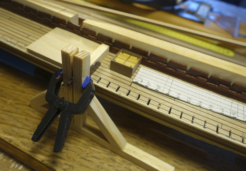
Further supports were inserted between the middle ones and the yokes.
- fmodajr, Gimo and GrandpaPhil
-
3
-
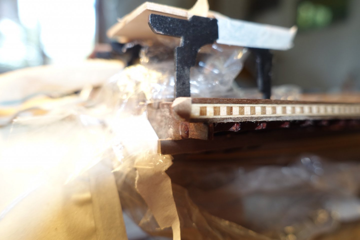
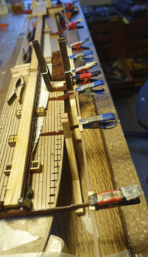
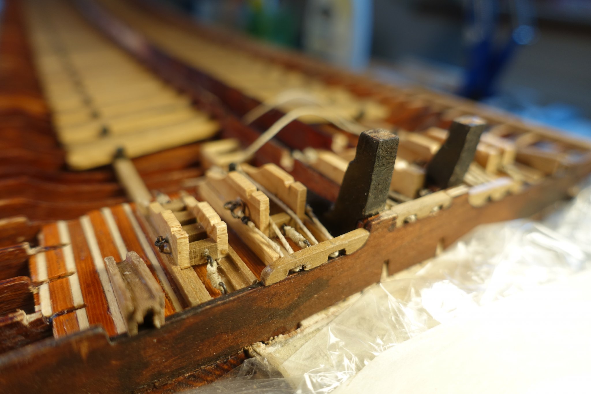
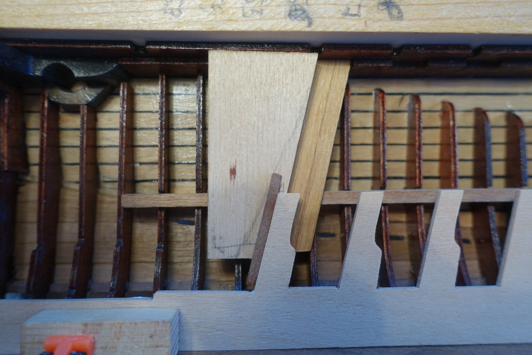
Regarding the bitts for fixation of the foremast; I had a discussion with Frank (fmodair) some time ago. Pictures of La Reale and some of other galleys show that there is a deviation of 5-7 degree of the foremast from the vertical axis due to the special handling of the lateen sails.
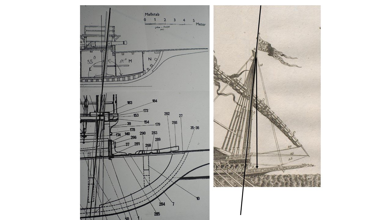
It declines toward the bow. In the Corel plans, the foremast is shown in a vertical position.
I decided to follow the paintings and drawings. To follow them, the deviation of the foremast of the vertical axis has also to be reflected in the tube to be drilled into the bitts. I have tested the decline with some wood pieces simulating the bitt and the foremast.
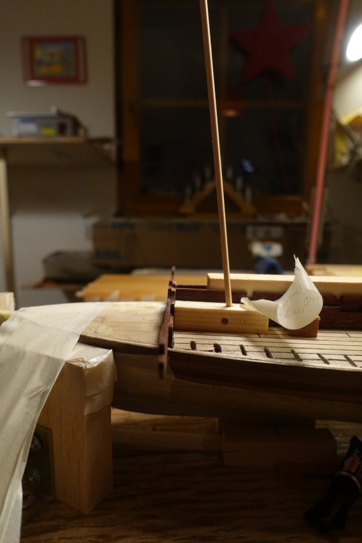
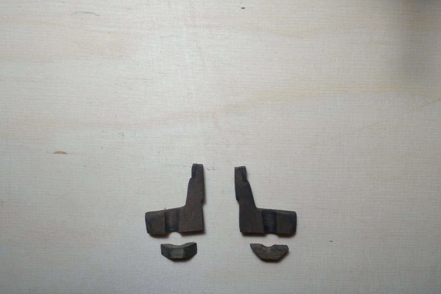
Moreover, I do not believe that the bitts were strong enough to withstand the enormous power of the big sail, i.e., the foremast had to fixed at the keel line. Such a fixation is also shown in the Mondfeld plan of the galley La Dracene. Thus, I made surroundings for the foremast fixation.
Next step is adapting the supports for the oars., which is probably the most difficult part
- fmodajr and GrandpaPhil
-
2
-
23 hours ago, fmodajr said:
Clark,
Thanks for your input. I am stuck using acrylics. I have to match the red and the blue that I am already using on my model. I will give it a try using the techniques shown to me from Michael, Mark and Grandpa Phil.
Thanks,
Frank
Some recommend to mix the paint with PVA to get an uneven result. I am eager to read the news on your post.


Reale de France by Clark – FINISHED - Corel - Scale 1:64
in - Kit build logs for subjects built from 1501 - 1750
Posted
I read the build log of Gimo who built the Reale back in 2013. He showed a nice suggestion to pep up the stern (kings?) platform. I also thought about planking the stern platform and decided to put a compass symbol on it, remaining planking has to be done in a diagonal shape. Template was drawn using Power Point.