


JSGerson
-
Posts
2,482 -
Joined
-
Last visited
Content Type
Profiles
Forums
Gallery
Events
Posts posted by JSGerson
-
-
As you know, there are a lot of pictures of the USS Constitution on the web (just not well organized), but it is nice to have your own personal pictures. Sorry you missed out touring the ship. I grew up and lived in the Boston area till the late 70s, so I visited it a number of times. My last visit was in November 2014 just before it started its last restoration. By that time, I had already purchased the MS kit and was a couple of years into collecting and organizing images of various detail of the ship to help with the construction of the kit. Presently, I have over 4,000 photos of the ship from 1857 to the present. Should you or anyone else need image(s) of particular detail(s), there is a good chance I have it. Just let me know.
Jon
-
Gregg, it's taken me 7 years to get this far, so hopeful I'll be working on the spar deck in months instead of years from now!😁
- PaddyO, Stevenleehills, Nirvana and 2 others
-
 5
5
-
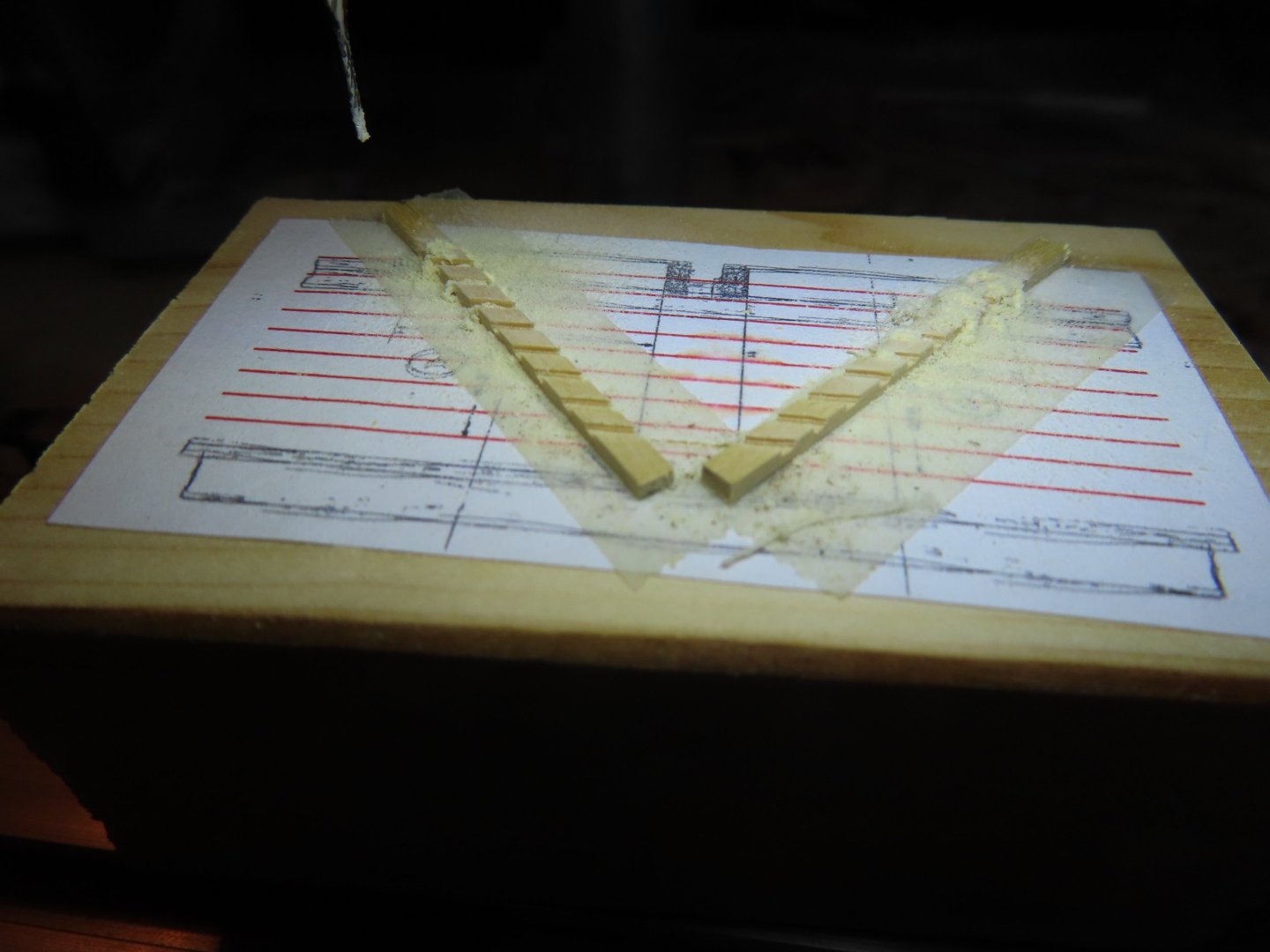
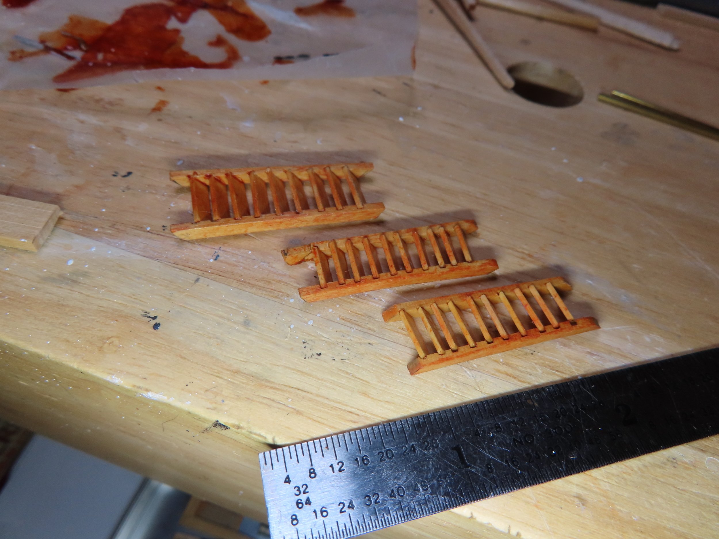
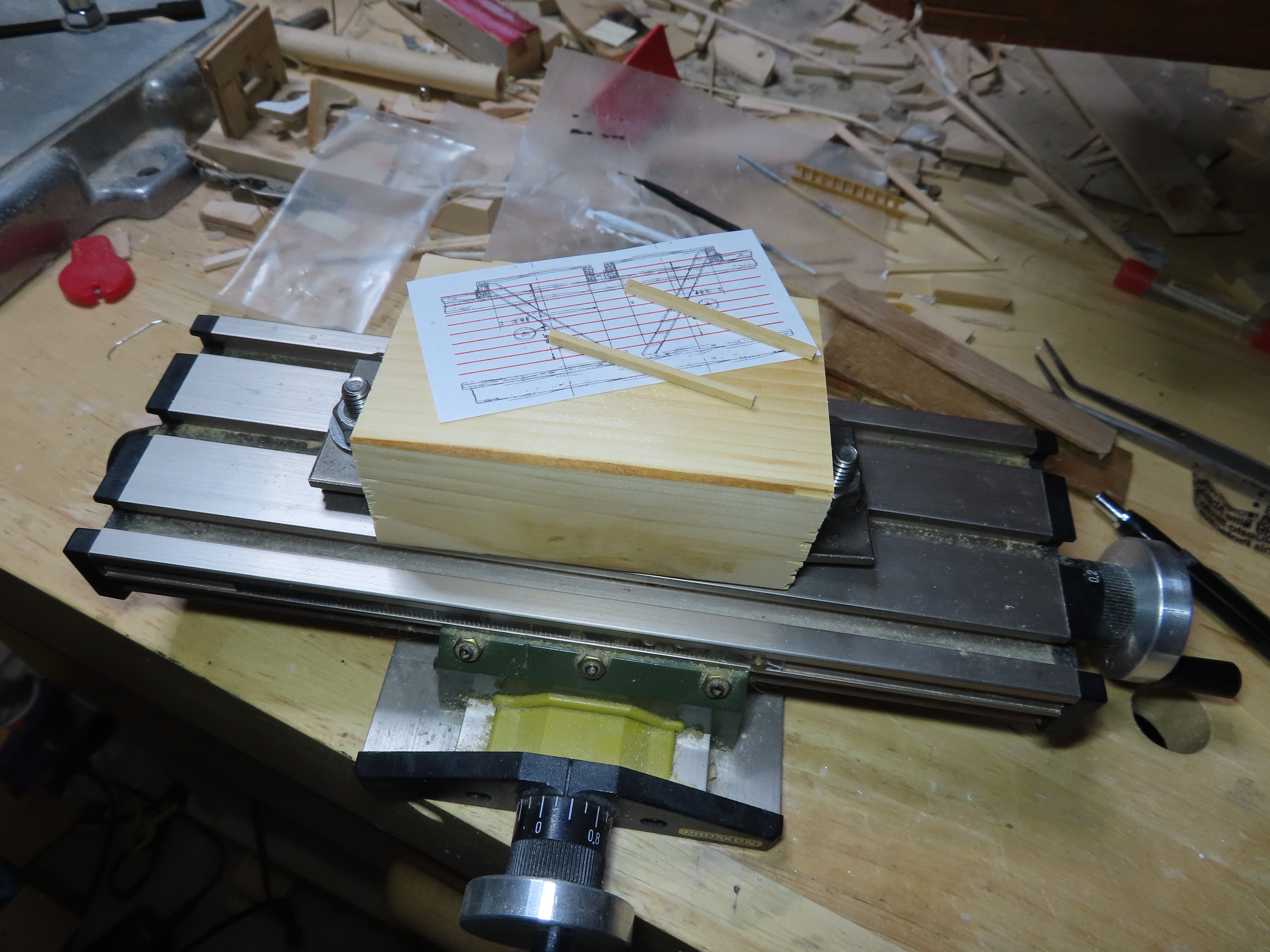
Then I had to do it all over again for the main hatchway ladders were fabricated. This time because the two ladders were identical, the grooves in the four sides were cut at the same time. These will be installed when the hatches are. Mustafa made it look easy.

-
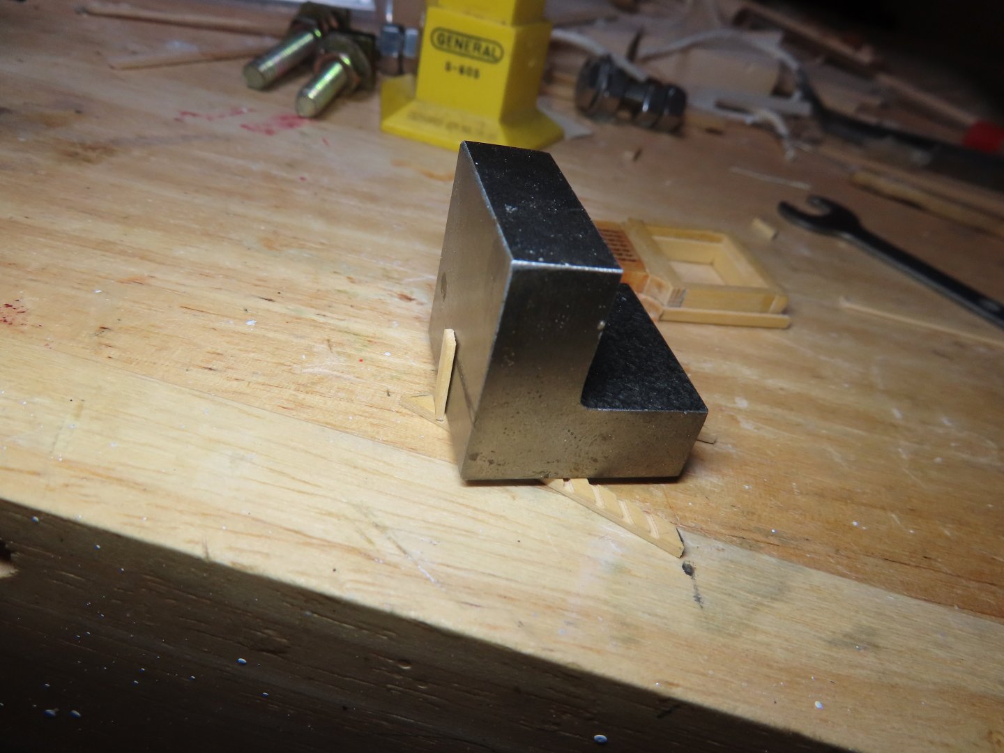
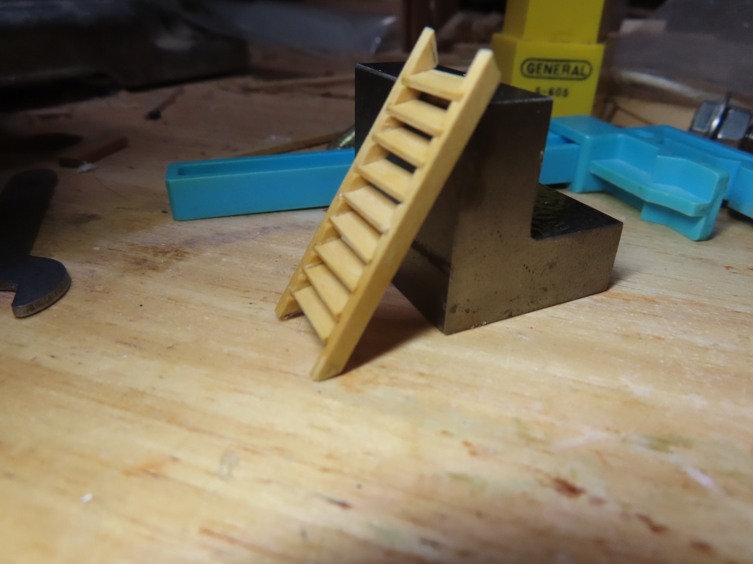
I initially used white glue to install the steps one at a time with a right-angle block. This allowed me to adjust the steps. Once all the steps were glued to one side, it was a little like herding cats. All the steps had to line up exactly to their counter part on the second side piece before it would all come together nicely. The results were not perfect, but better than my previous attempts. Here is a dry fit. Although the access is closed with the grating, you might be able to see part of the ladder from other openings in the spar deck. I will probably remove the grating when it’s permanently installed.


- PaddyO, Nirvana, Dave boatswain and 5 others
-
8
-
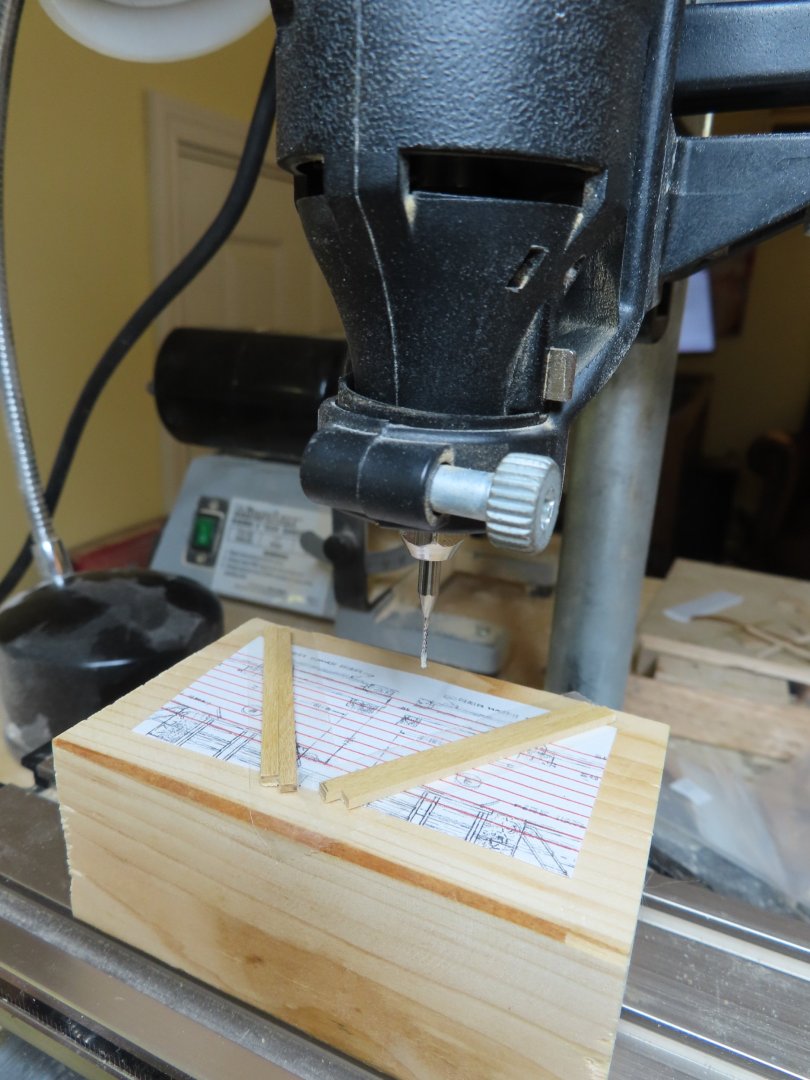
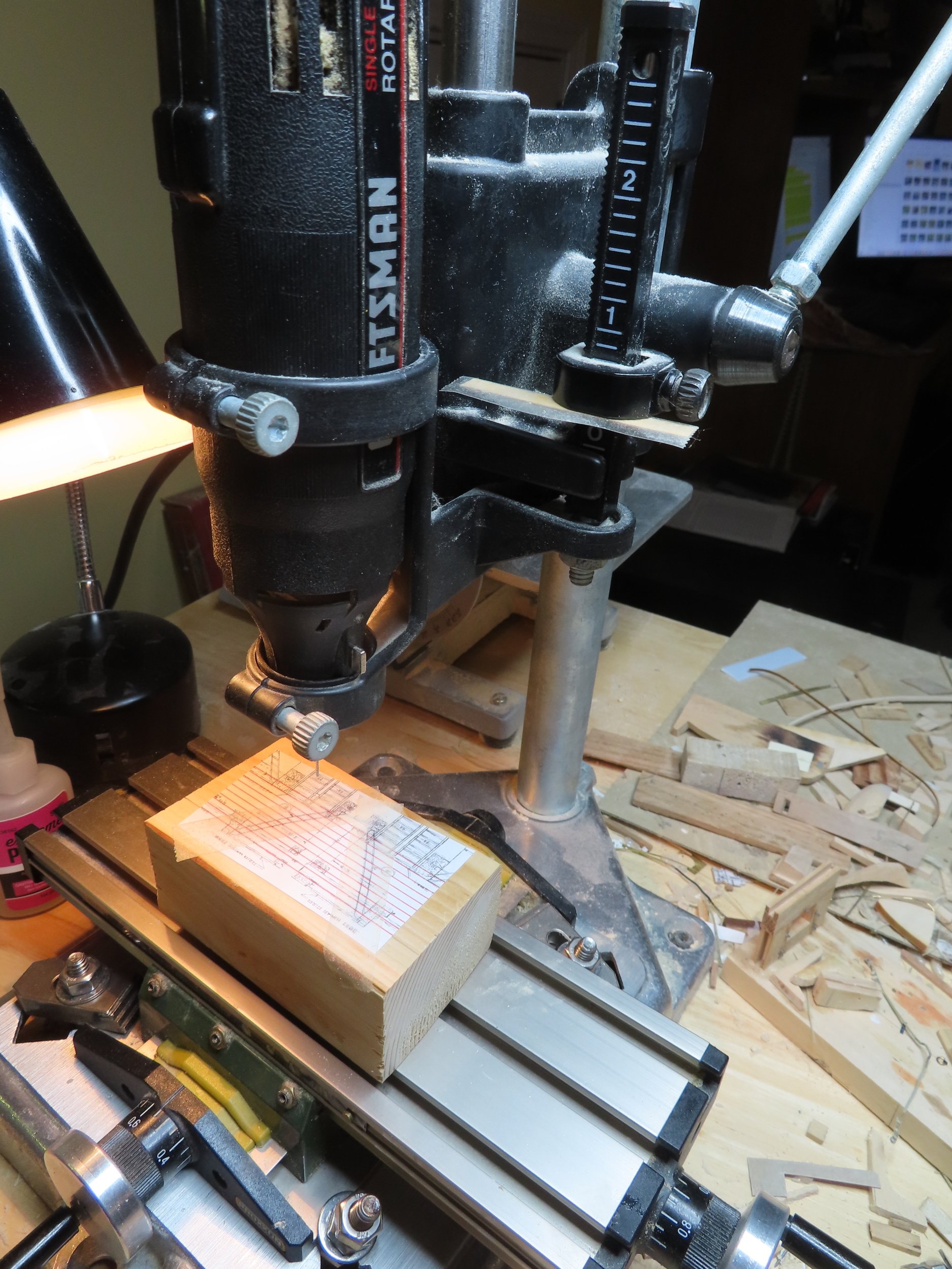
The Dremel drill press stand is not a precise instrument. I needed the router bit to stop precisely 1/32” above the X-Y table when I lowered the Dremel to its stop position to cut the 1/32”x1/32” groove in the 1/16” thick side pieces. Unfortunately, the drill-stop only adjusted to 1/16” increments. I had to use a piece of scrap 1/32” wood inserted in the drill stop.
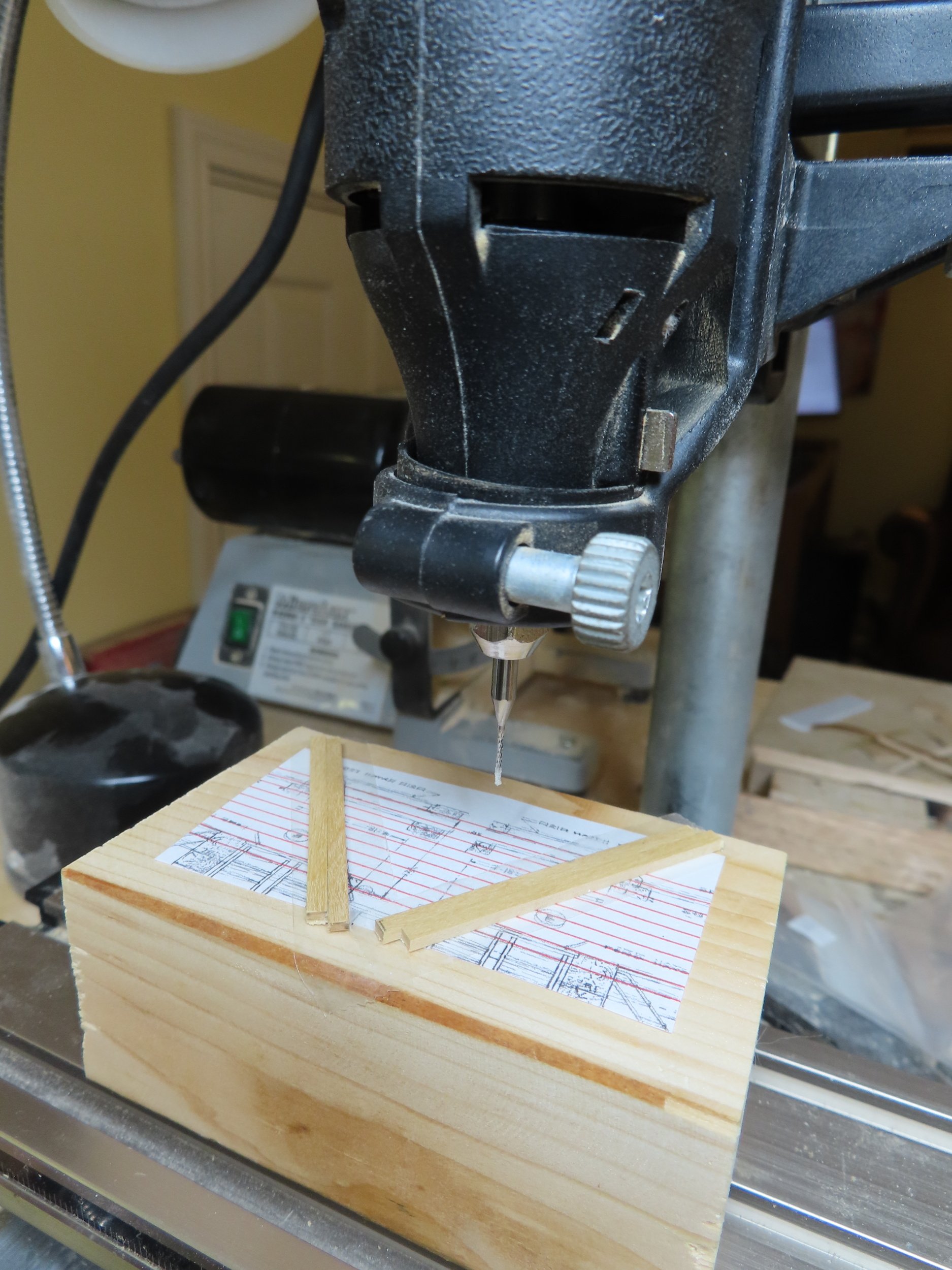
Because the X-Y table is just clamped to the drill stand, aligning the block with the ladder images as well as the X-Y table to the stand was very tricky and tedious. The X-Y axis of the table must match the X-Y axis of the ladder images. This in turn must align with the drill bit so that the cuts match the images when the table cranks are turned. Finally, I got it all working after a couple of false starts.


- PaddyO, Nirvana, Geoff Matson and 3 others
-
6
-
There are several things that still must be accomplished on the gun deck before I can start work on the spar deck. They are:
- Ladders going up to the spar deck.
- Main mast bitts
- Capstan and its related anchor ropes and chain
- “Temporary” support posts under the main hatchway
Ladders
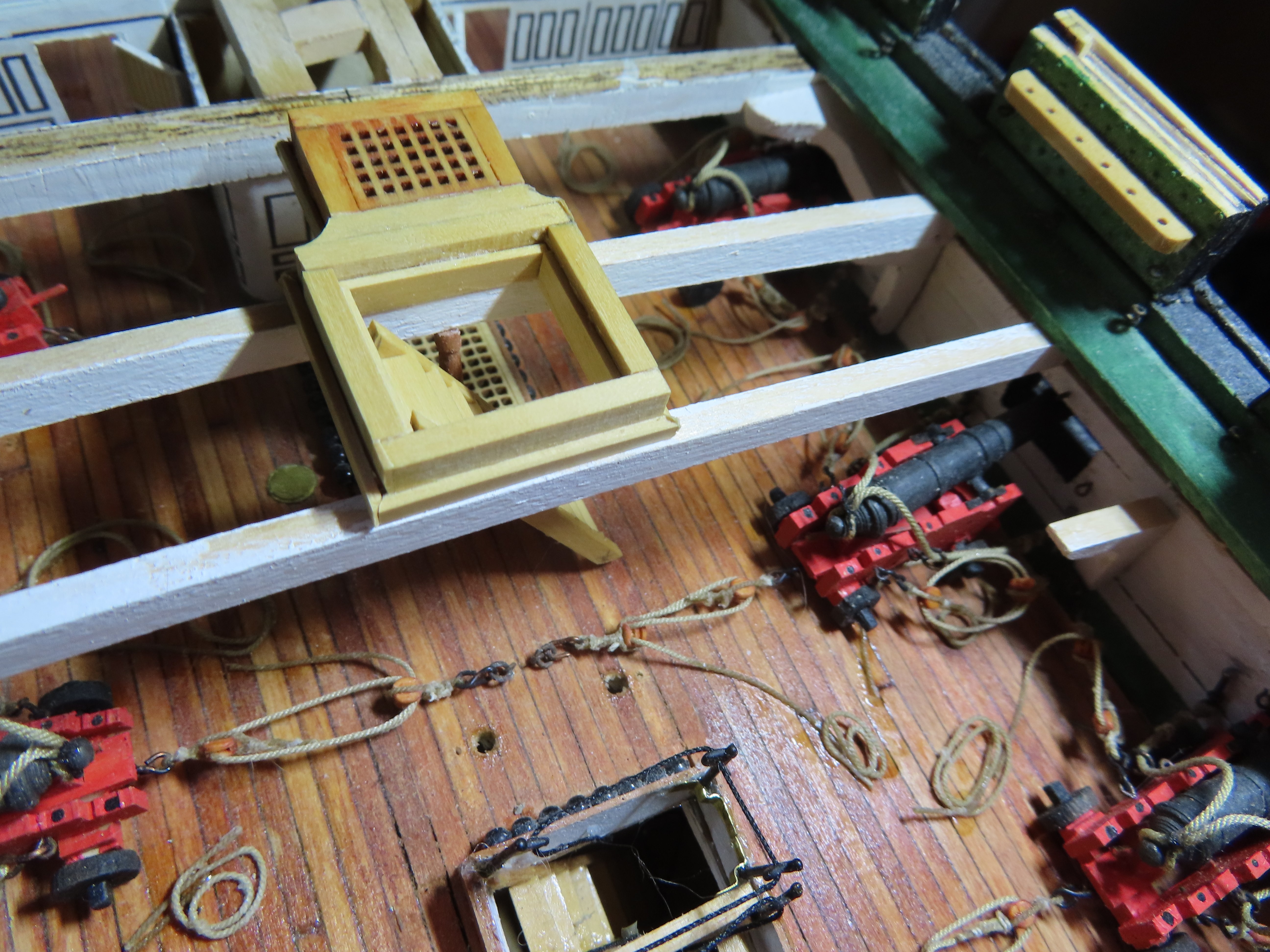
The first item I attempted was the ladder leading up to the double hatchway by the ship’s wheel. I figured this would be a good one to do first because if I don’t do a decent job here, it would be hidden under the grating I presently have in the hatch.
I have yet to make a ladder to my satisfaction starting from my first POB model, Rattlesnake. Because of my dissatisfaction, I haven’t made ladders the same way twice each time trying a different method. This time, I am taking my cues from Mustafa (aka mtbediz, post #340)
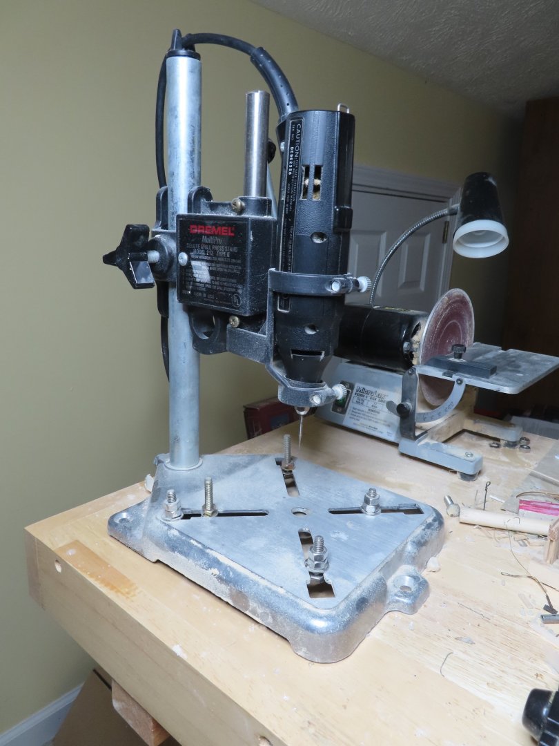
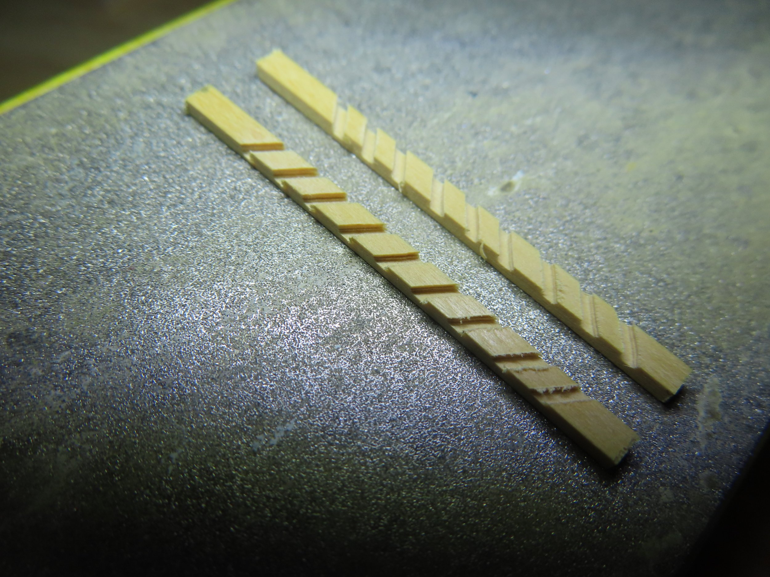
Mustafa has a real drill press, something I don’t have. So, using my Dremel rotary tool, an old version Dremel drill press accessory, and a Proxxon X-Y table, I rigged an ad hoc drill press. I mounted a normal and reverse image of the US Navy plan for the ladder on a wooden block with double sided tape. The sides of the ladder were to be 1/8”x1/16” and the steps 1/8”x1/32” boxwood, also mounted on top of the plan images with double sided tape. Then the wooden block itself was mounted on the X-Y table with double sided tape. A 1/32” router bit was installed in the Dremel to cut grooves in the ladder sides 1/32” deep to accept the steps.

- Unegawahya, Geoff Matson, Nirvana and 3 others
-
6
-
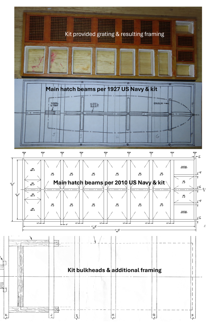
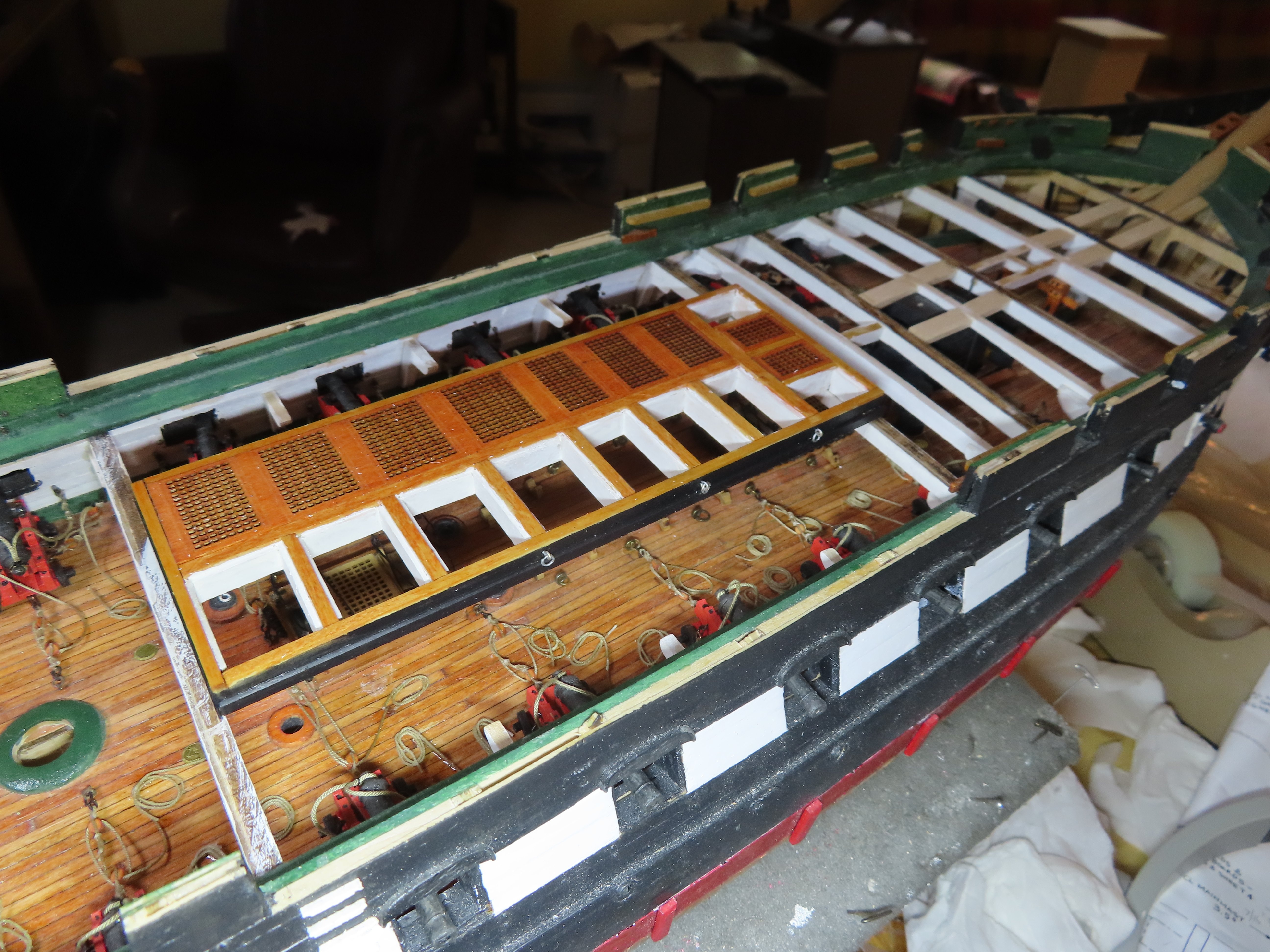
The fabricated main hatchway DOES NOT match or align with any plan!
The biggest surprise was that the main hatchway DID align closely (although not perfectly) with the pre-installed knee supports on the gun deck bulwarks which were “eyeballed” into position. If I had just looked far enough ahead to understand all the interconnections or had a consistent and complete set of construction plans. I might have had a little better alignment at this point.
If one fabricated the kit as designed like Mr. Hunt did, there would be no problem; all the beams would be hidden. The 1927 and 2010 US Navy plans for the hatchway support beams match closely with the kit (which was based for the most part on the 1927 restoration). The kit plans even indicated the removal of the aft ladders during the 1996 restoration. The kit’s laser cut gratings, however, do not match anything I can find in the US Navy plans and the gratings design are not even shown on the kit plans. So, my model will be a Frankenstein combination of components and adjustments that may look good to the layman but won’t be accurate. So be it and move forward. Below are some dry fit ups.


-
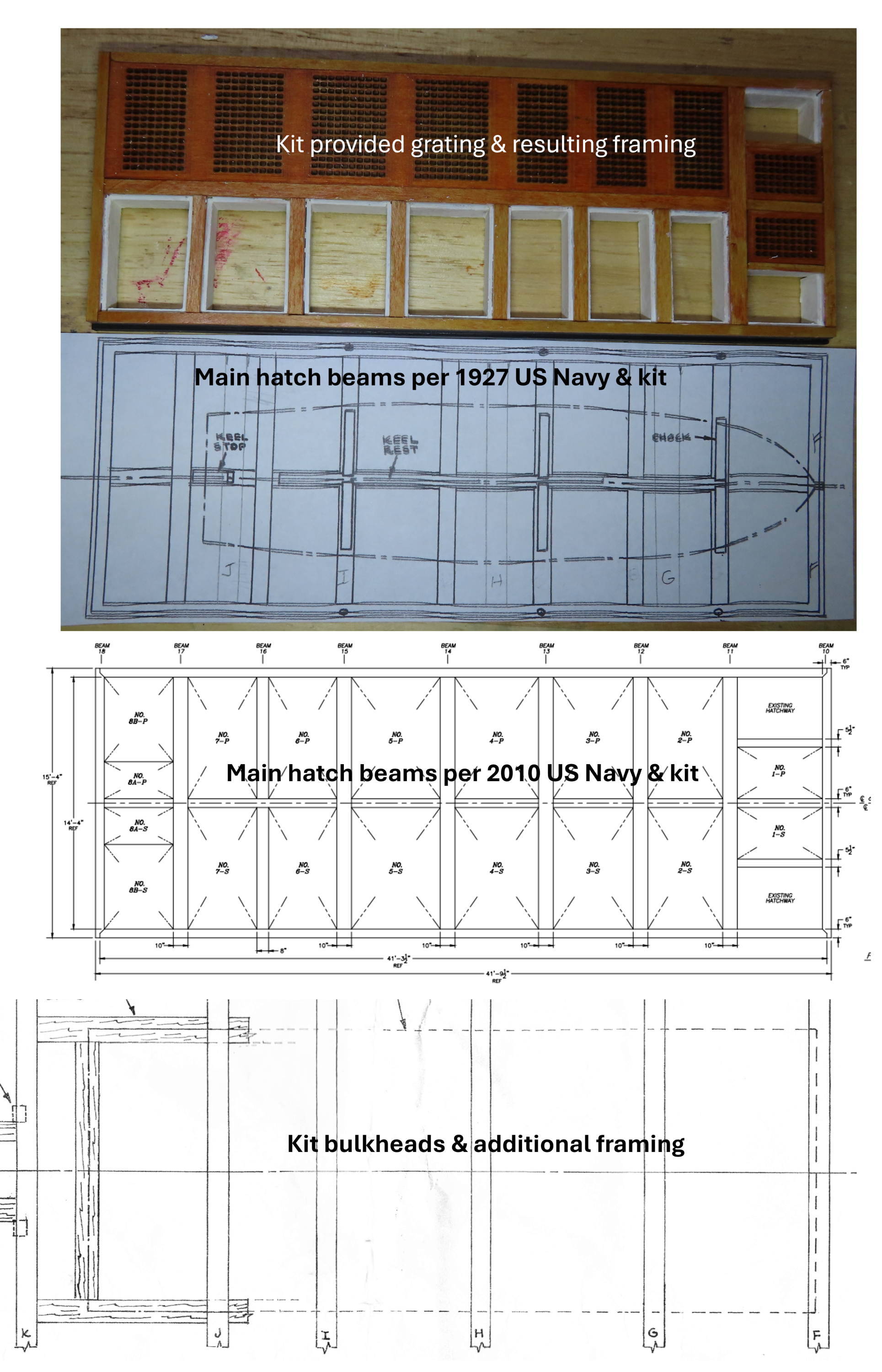
The main reason the hatches were fabricated at this point was to workout the alignment with gun deck bulkhead spar beams. If you look at the image below, you will see the comparison of the:
- Assembled main hatchway based on the kit’s gratings,
- 1927 US Navy Main hatchway beam plan which matches the kit’s plans,
- 2010 US Navy Main hatchway beam plan which also matches with the kit,
- Kit bulkheads beam plan.
- Nirvana, Ryland Craze, mtbediz and 2 others
-
5
-
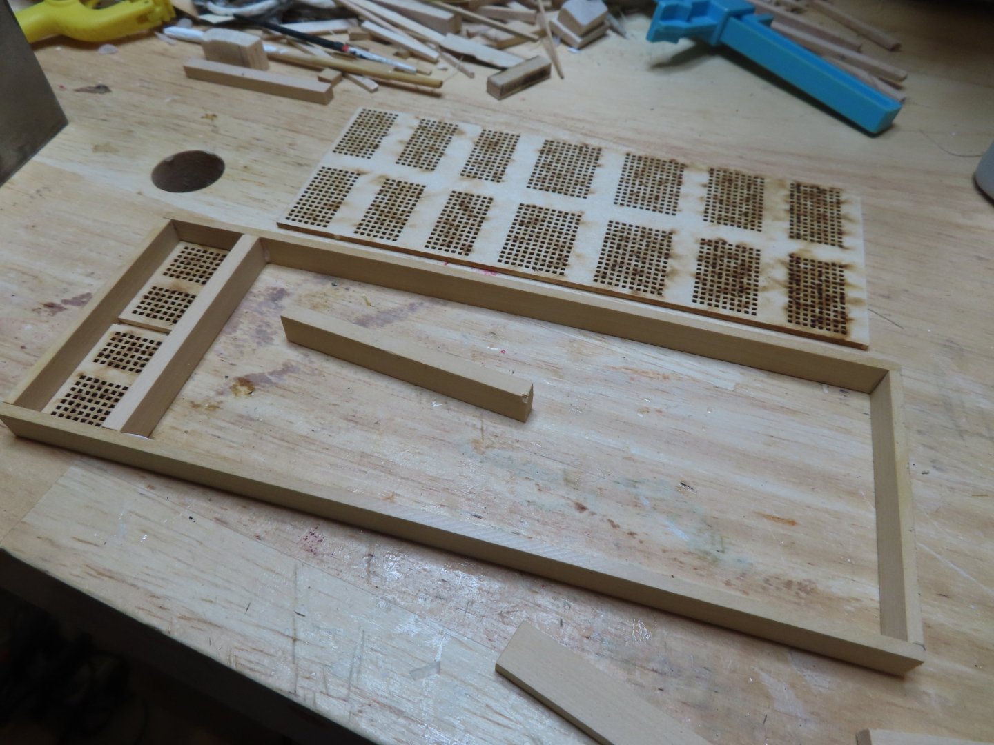
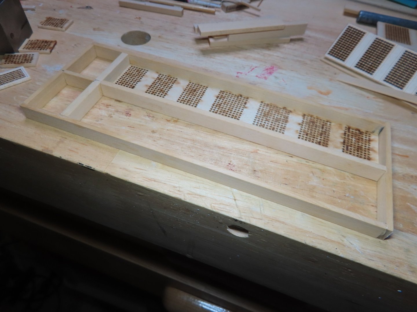
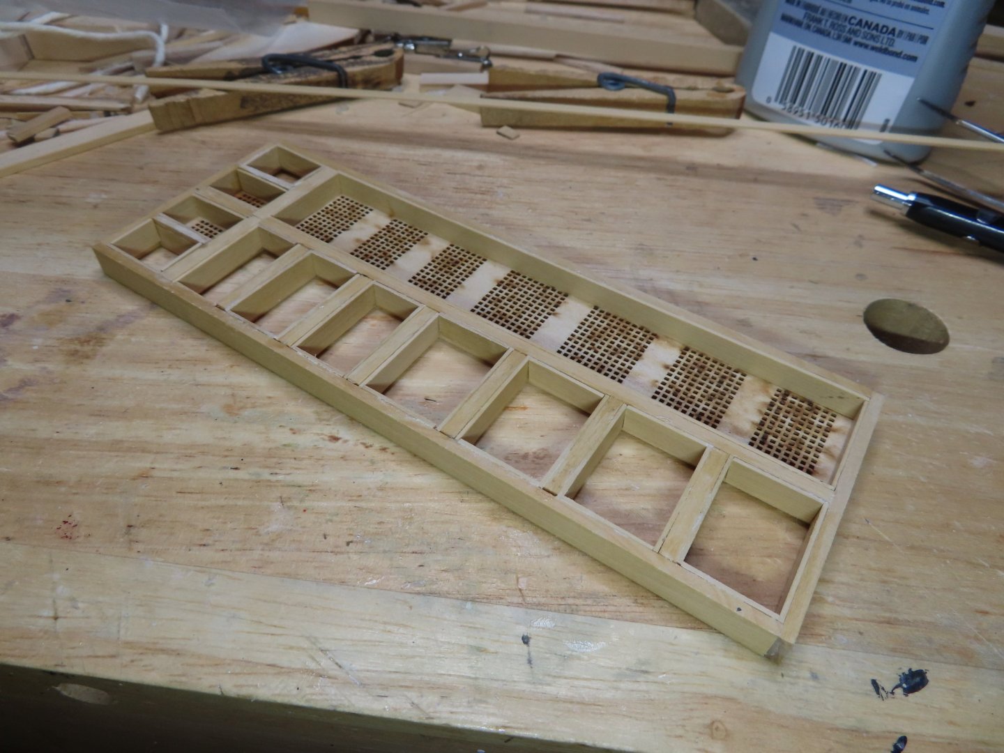
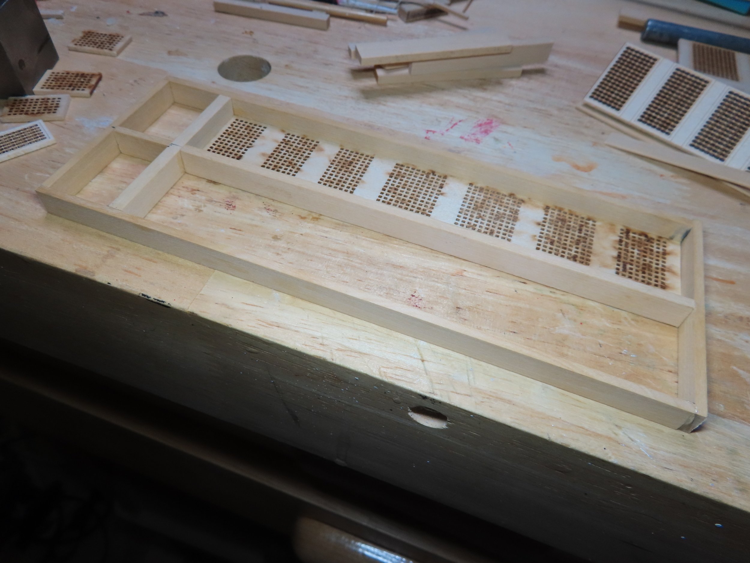
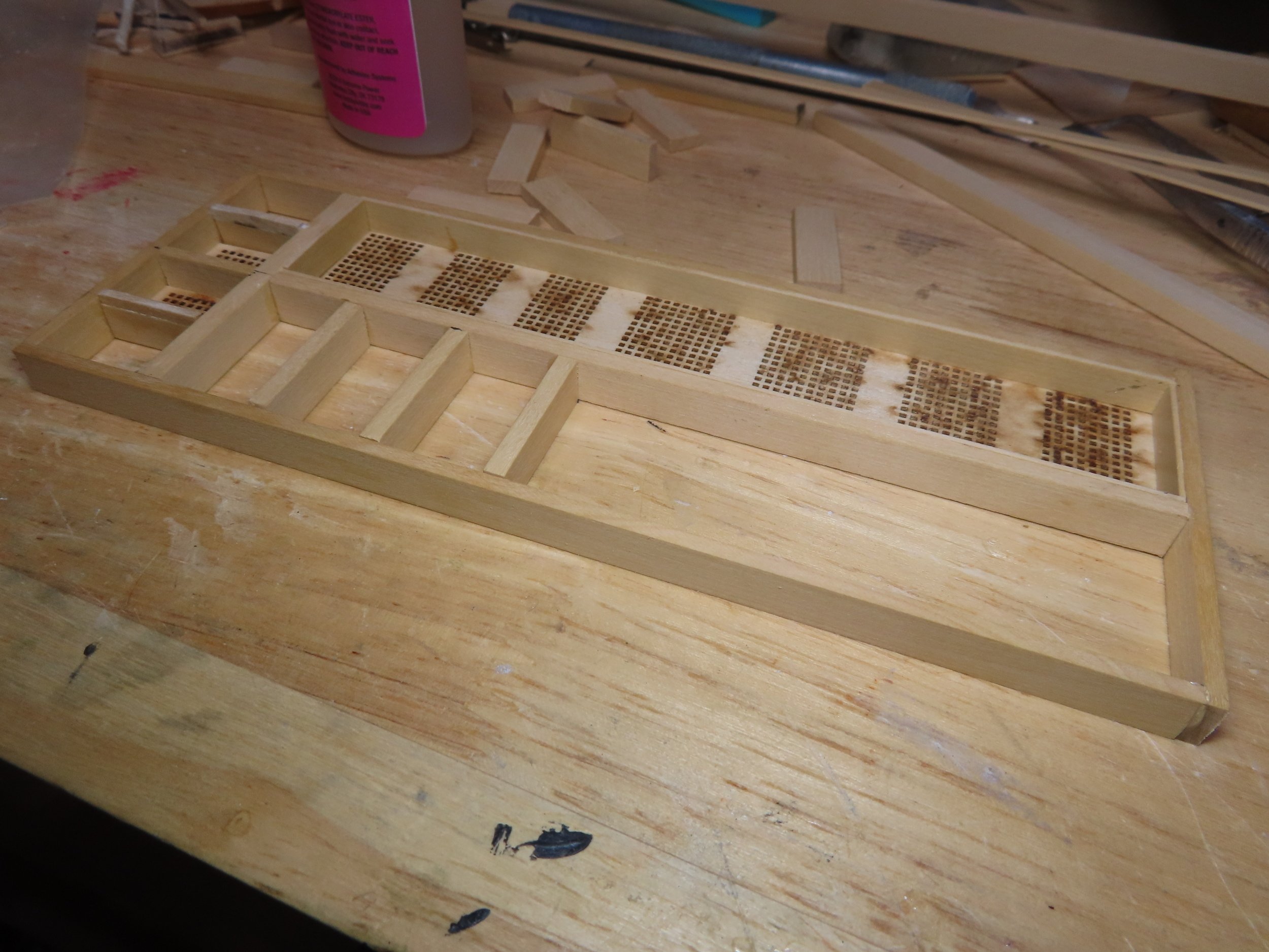
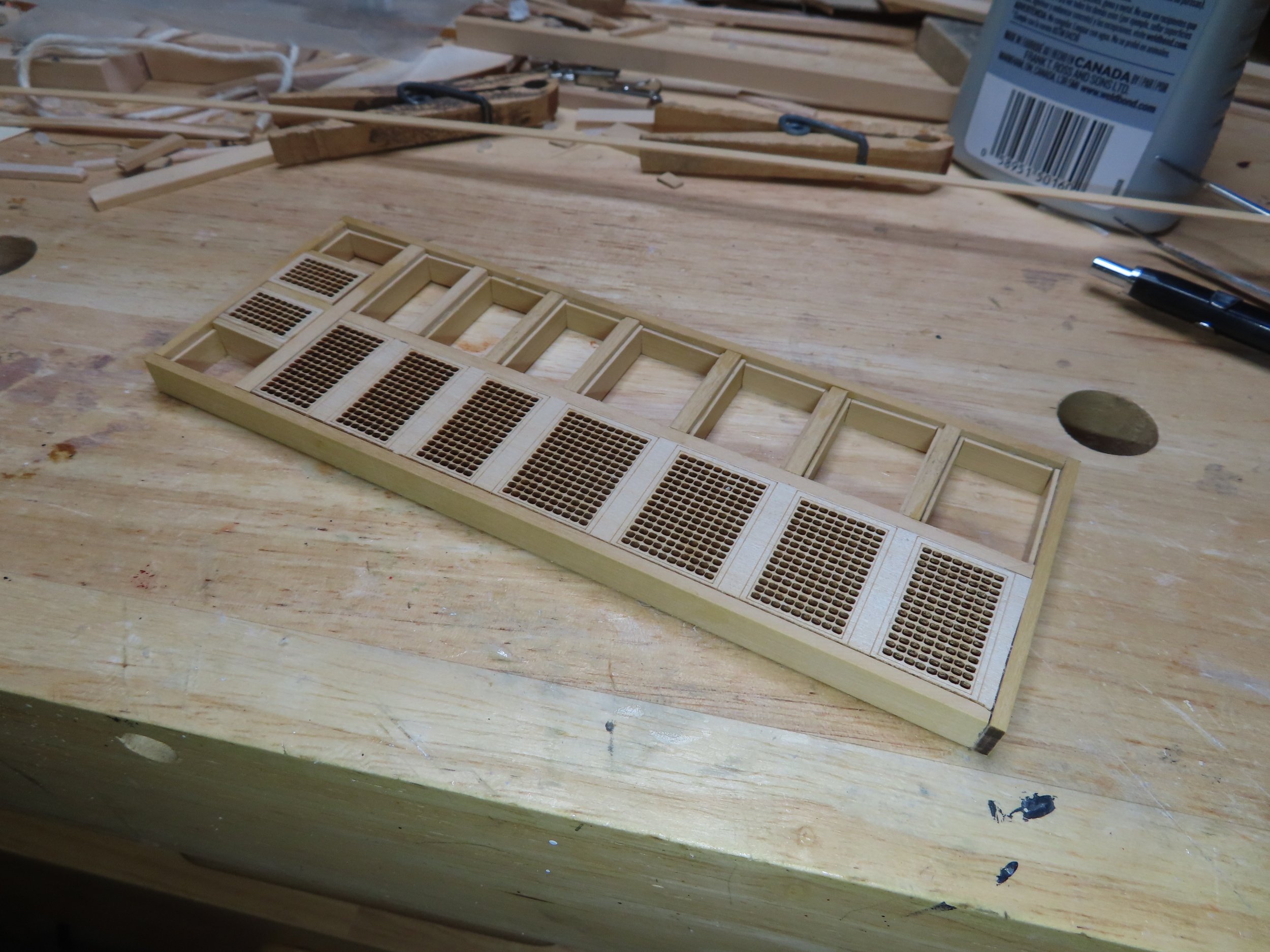
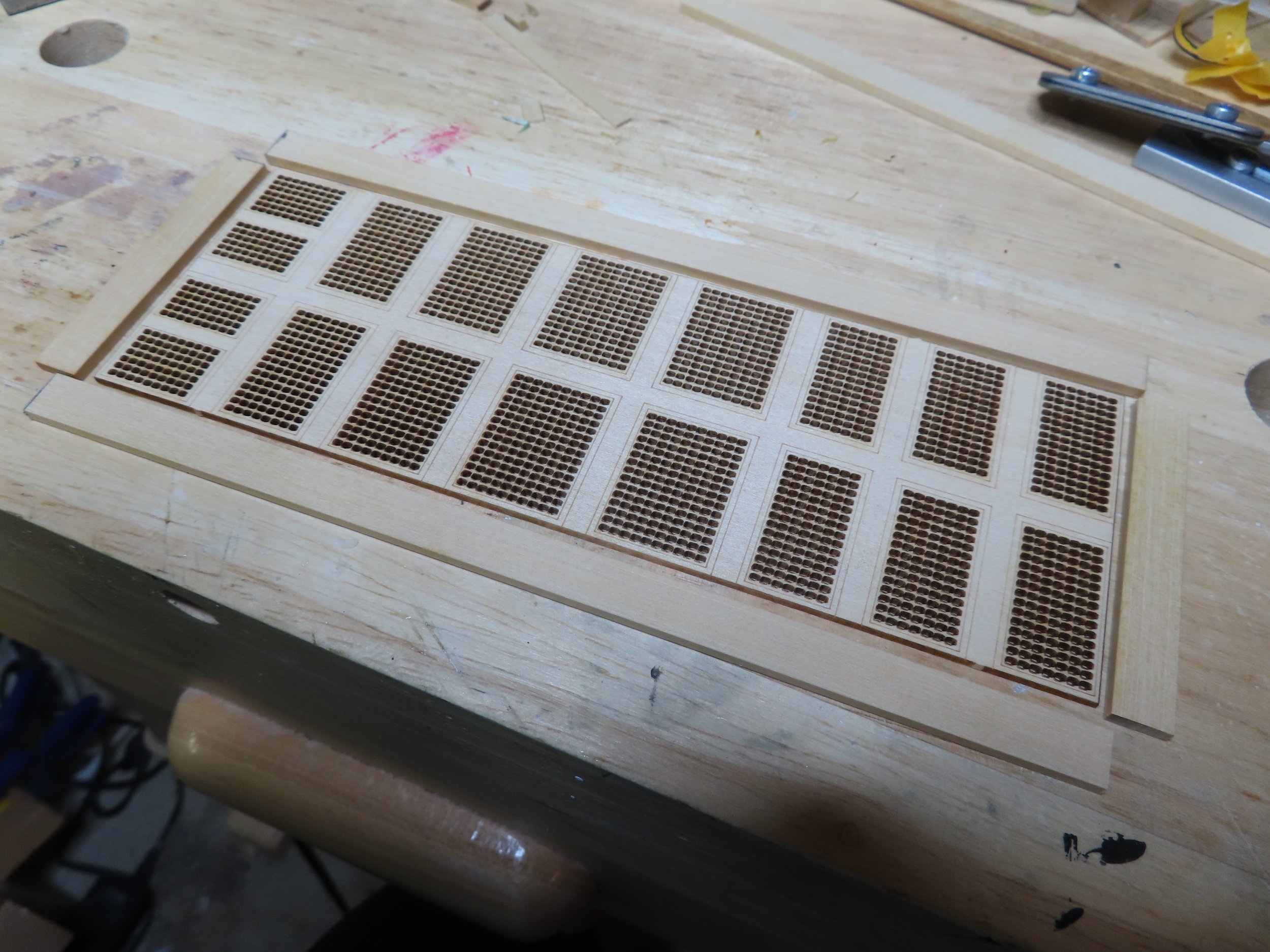
The remainder of the main grating was sliced lengthwise. One half remained intact, while the other was cut again into individual gratings. It is to be noted that there are six different size gratings that comprise the 18 total on the single laser cut piece. So as not to mix them up, I only cut off what I needed, before I moved on to the next one using them to set the next beam frame in turn.
The internal framing was made from various pieces of 5/16” x 1/16” boxwood which I had to mill myself on the Byrne’s Saw. The supplemental wood package was based on the practicum which did not address removing grating to reveal underling structure.
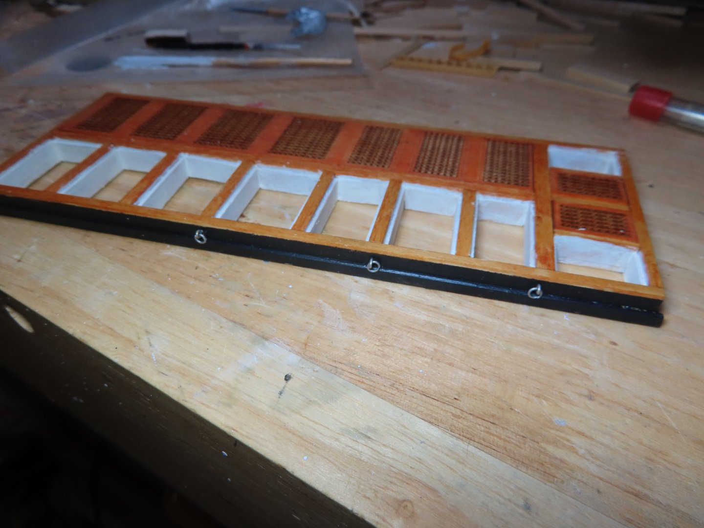
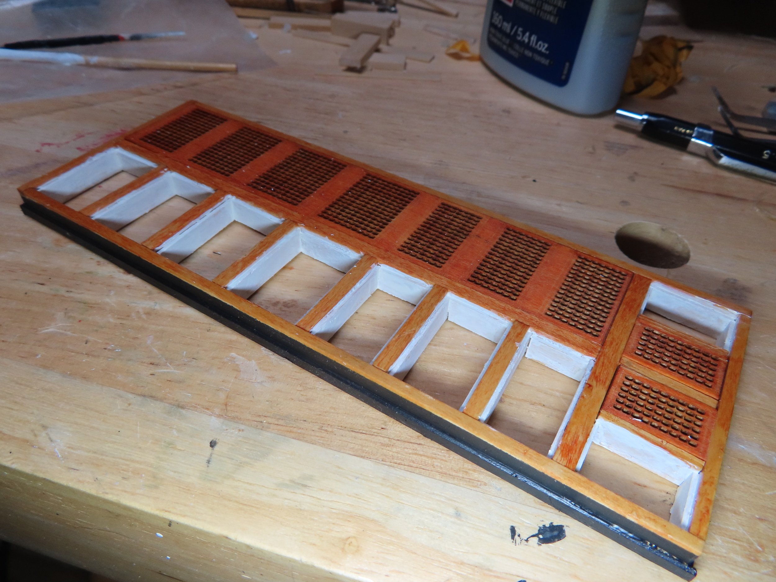
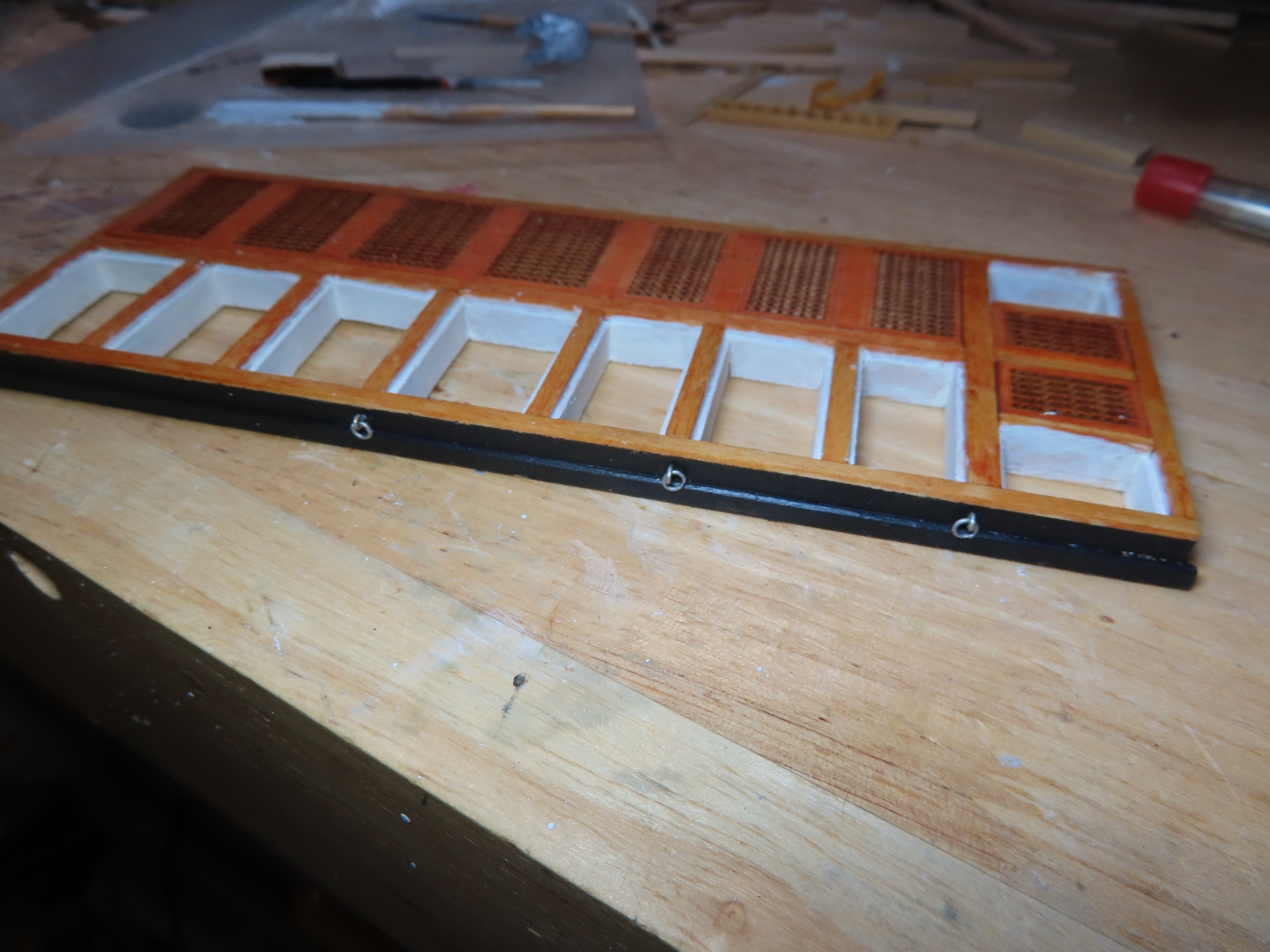
Using 1/8”x1/32” boxwood, the internal lip was created to support the intact remaining long grating as well as the individual open frameworks. Finally, the assembly was stained and painted. The last components to be added to the main grating frame were the six eyebolt and rings assemblies.


-
The Main Grating
If I was following the kit instructions (what there is of them), the main grating would be very simple; just build a border around the laser cut main grating provided by the kit and it would be done.
If I were following the practicum, it’s a bit more complicated. Mr. Hunt would have you slice the grating lengthwise and add a support beam down the length of the full grating using complex lap joints.
But, if you plan on leaving half of the gratings open, and adding ladders to the gun deck so that the gun deck can be viewed, it’s almost a complete scratch build.
The exterior border frame, which is taller than the other grating frames, was fabricated just like all the other frames using the boxwood pieces (provided by the wood supplement package). The 5/16” x 3/32” boxwood was cut as follows:
- 2 pieces: 6 9/16” lengthwise
- 2 pieces: 2 5/32” beam wise
These pieces were glued together with butt joints creating a large open frame.
Next, I held my breath as I cut off the four most forward gratings with the Byrnes Saw. These were used to set the first internal beam frame. The two outer corner gratings will remain off the framework to allow the installation of ladders to the gun deck.

-
Woodartist: I feel flattered. Remember, the Conny is only my second square rigged ship and third wooden model. So take everything I say/do with a grain of salt. I am an experience amateur, not an expert. It is why I explain what I do so that the reader may avoid any mistakes I may have made.
Jon
-
I do something similar. I've copied every Constitution log I've ever followed, some good, some not so good: 38 on going; 25 now completed; 26 dormant, logs never completed. This is how I've been able to locate information quickly from these builders. I can do word searches on their complete logs without having to go page by page on the websites. (BTW, I don't trust websites; they crash, disappear, and change location of their pages.) Should there be something interesting like an impressive jig or construction method I may want to use, I will copy and paste that portion of the log as a separate document and file it in the appropriate subject folder for easy reference. I also collect images of the real ship. A lot of the images you can't find directly with a search engine I gotten by looking for "A" and finding "B". They are all sorted into individual subject folders. I've got about 1,400 images; and the US Navy plans from various sources. Yeah, so I guess I am the reference guy.
Jon
- Stevenleehills, GGibson and mtbediz
-
1
-
 2
2
-
Wow, I didn't know I was the "go to guy" on research!
QuoteLooking at the plans you posted, are the deck planks that end in a point actual practice, now and in the past?
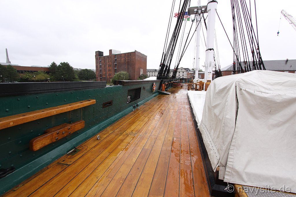
The only pointed planks I see are where the deck planks meet the waterway at the bow. These shown exactly the way look on the real ship. However, the hull planks, do NOT come to a point. Various methods are used to avoid that scenario, like using stealers and/or tapering. This is the way the ship is today. How it looked in the 1800s, I would not know. The earliest US Navy spar deck plan I have is from 1928, and there practically no difference from the kit's plans.
-
Beautiful planking job Pete!
-
Just about every surface of my model is covered with something, be it copper, paint, or stain. I have not used polyurethane (Wipe-On Poly)...yet. When I use paint, it's on bare wood so it soaks into the surface. I've used basswood, boxwood, and pear wood so far. The only wood I could have used the poly was the pear wood which was already the correct color I wanted. I didn't use it on the couple of wooden columns and bitts I made with it so far which are barely visible, but I may go back and touch them up with it.
And yes I too get cases of "analysis paralysis."
Jon
- Der Alte Rentner and mtbediz
-
1
-
 1
1
-
I am starting the main grating and only now have I looked closely at the laser cut piece. The individual 18 hatches ae not separated, yet your model makes them look (or actual are) individually set into the frame. Did you separate them, and if so, what method did you use? Any saw blade would reduce the material between the gratings after the cut. Yours appear nice and tight.
Jon
-
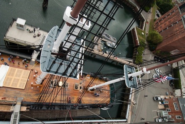
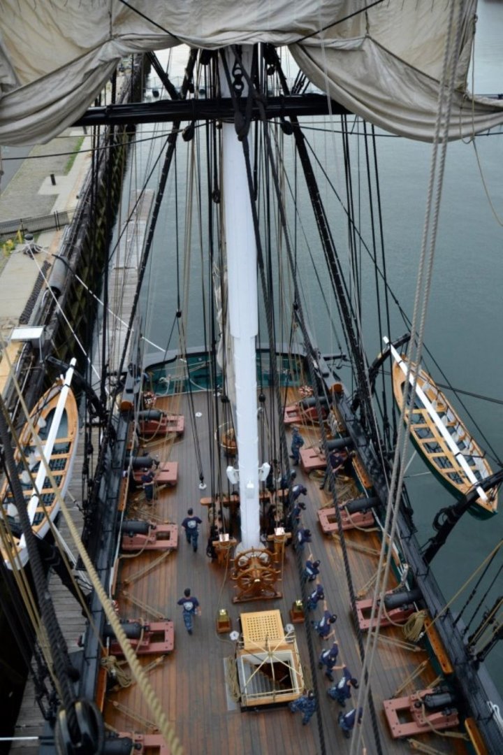
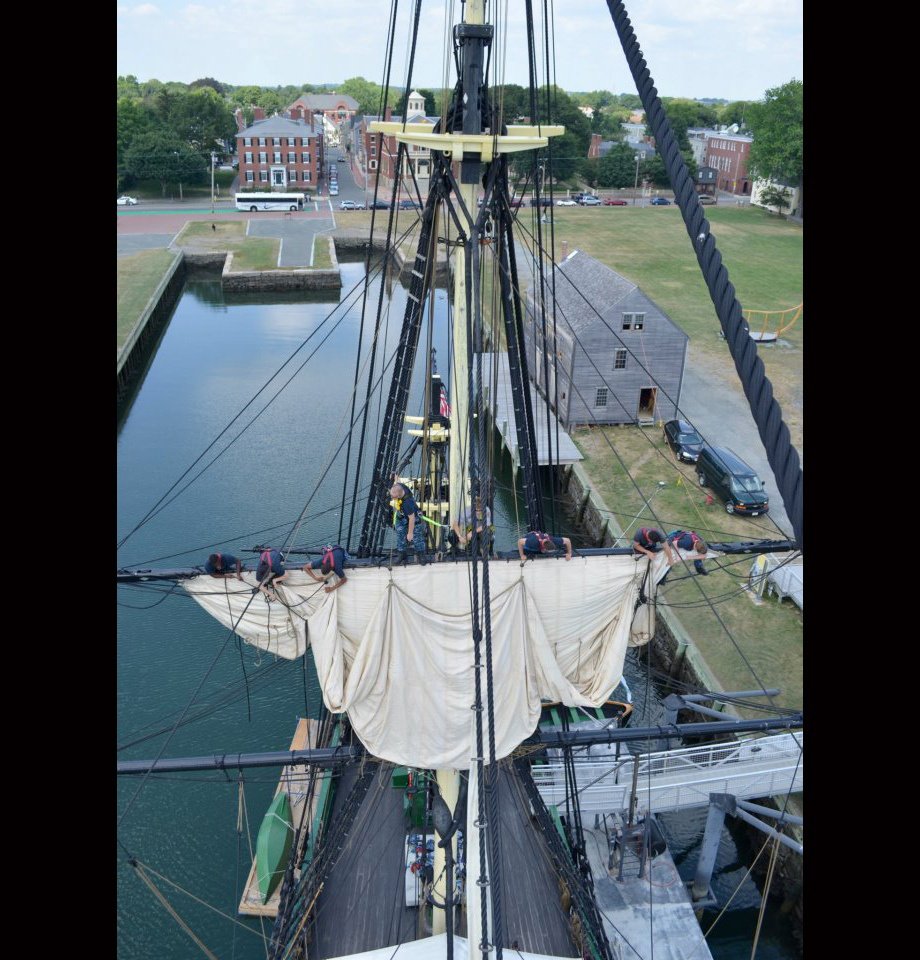
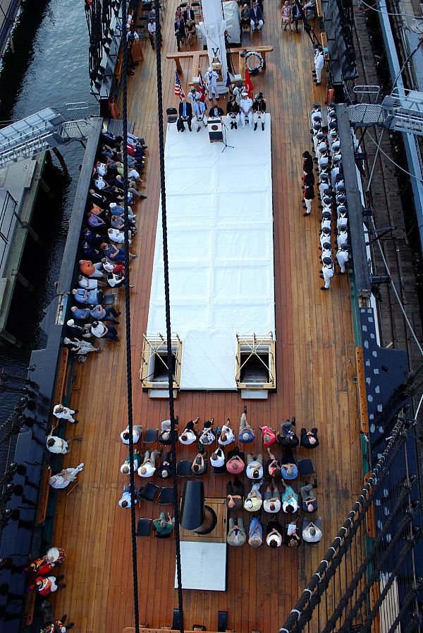
As near as I can tell, the tapering is subtle, but I will check it out in more detail when I get to that stage' Peter, here are a bunch of overhead shots of the stern. Any tapering is hard to see in these photos.
-
When I first started making models around age 10, obviously they were plastic, but I never liked the simple ones. I always chose the ones with the most parts, so most of the time I made modern ships and maybe a few cars and planes. No one I knew made models and therefore I was self taught. I wasn't even aware that you could buy paint. So although, I learned to assemble the kits fairly well they never looked as good as what I saw on the box. Boy, have times changed.
Jon
- mtbediz, PaddyO, Stevenleehills and 1 other
-
4
-
I've been following your conversations from afar about tapering the deck planks and I'm confused. I understand tapering of the hull planks because you're working on a curved surface. Just about every one of my planks near the the bow and stern were tapered. But the only tapering I've seen on the deck planks is where the planks converge and/or nibbed are at the bow. None the of images I've seen of the actual Constitution deck planks converge. Or are you talking about something else?
Jon
-
No blood, just the way the wood took the stain. Maybe sweat stain?
Jon
-
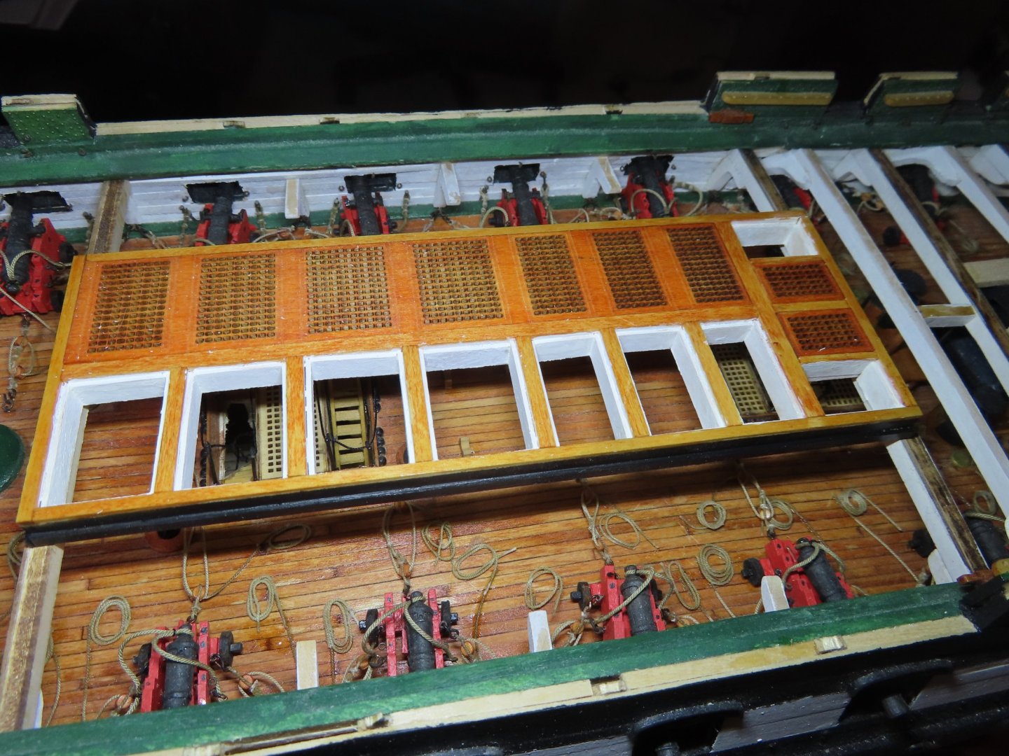
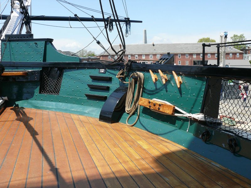
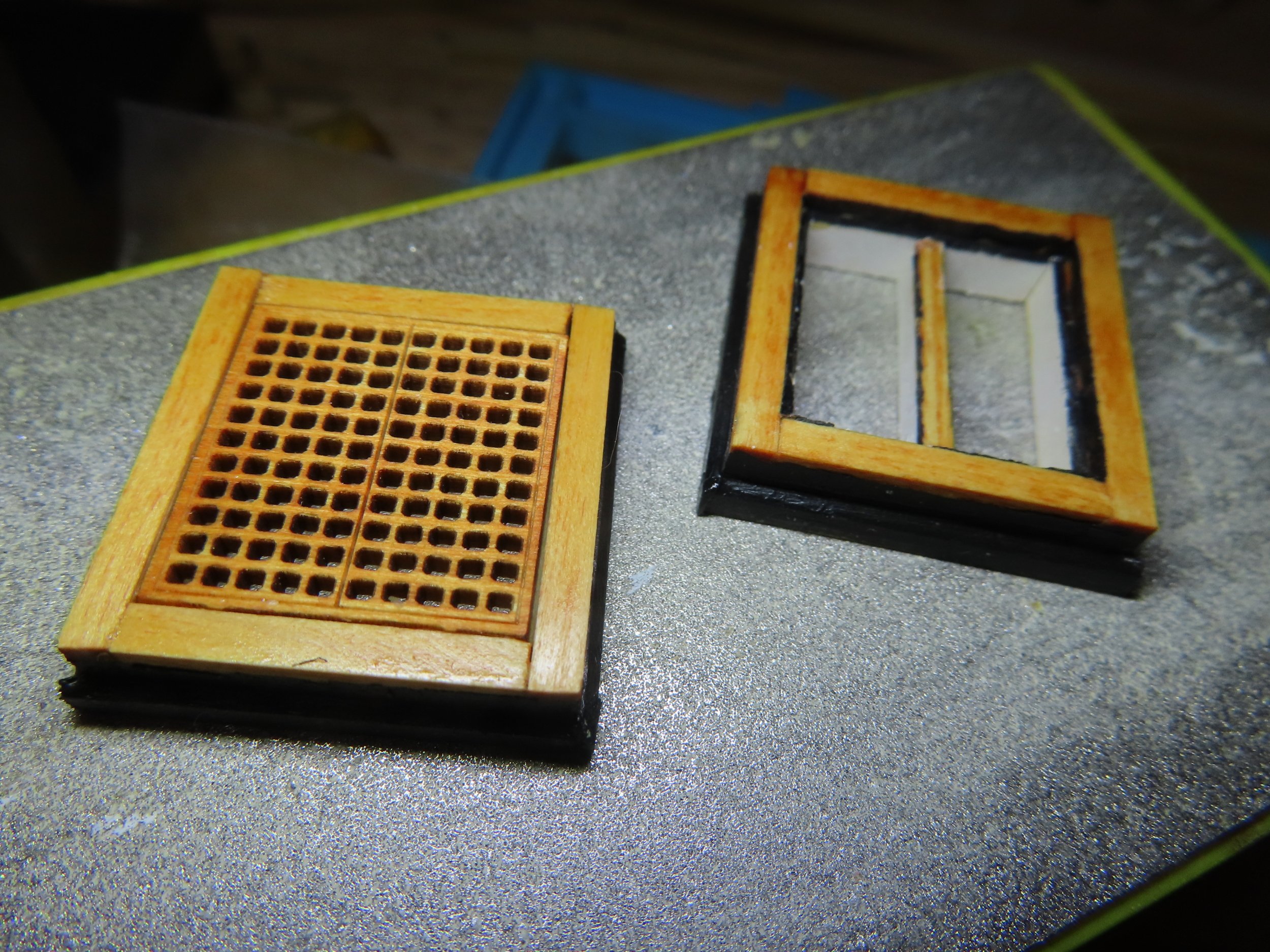
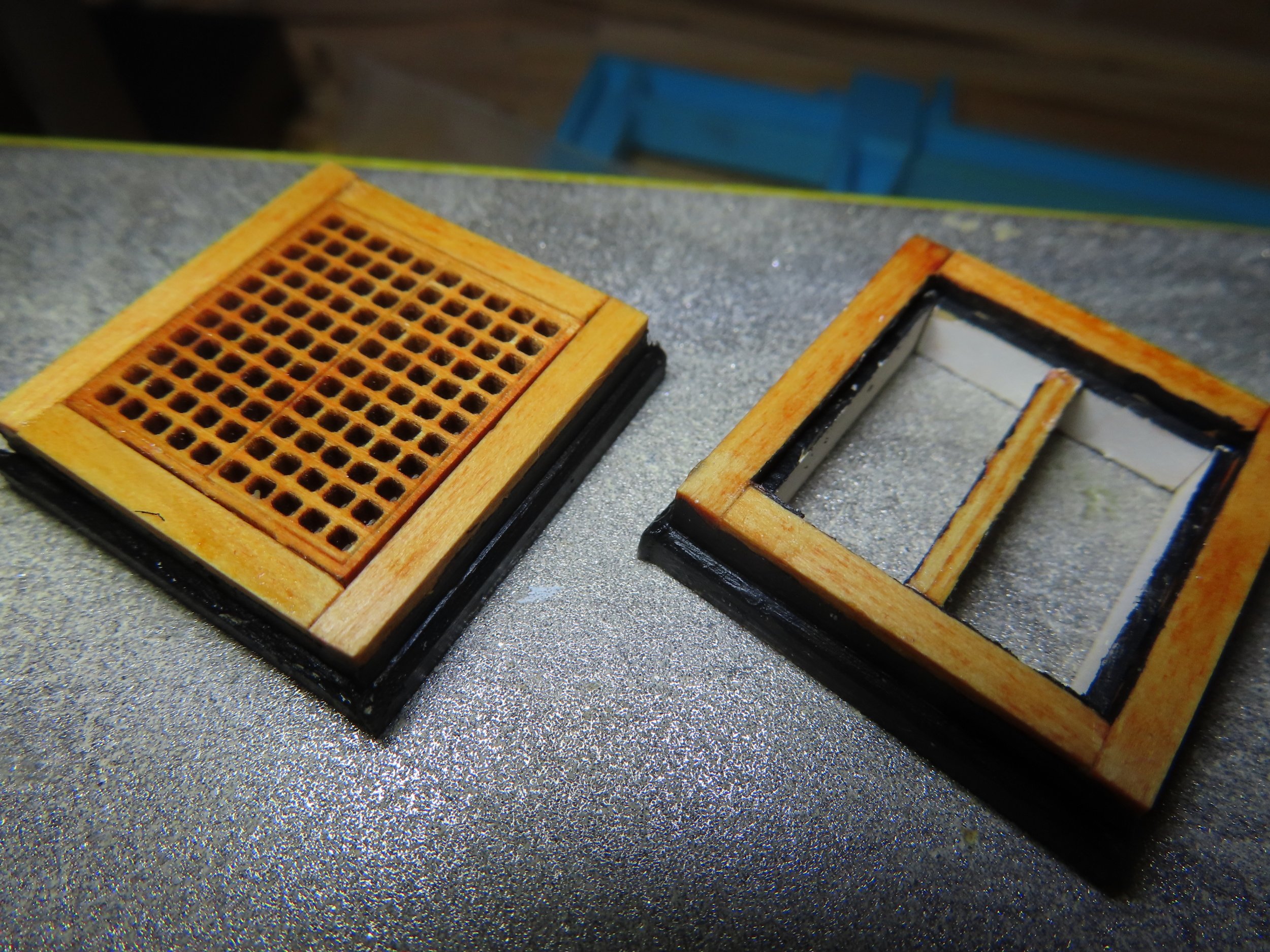
I also noticed that the painting scheme of the actual ship has again changed. You will notice the frames of all the hatchways presently have black trim, whereas prior to the 2015-2017 restoration, the frames had natural wood finishes. Since my model is based on the present ship configuration (with some exceptions), I painted these last two frames with black trim now because the interior elements had to be painted during fabrication and to see how they would look. The others will be painted later.
- Unegawahya, PaddyO, mtbediz and 1 other
-
4
-
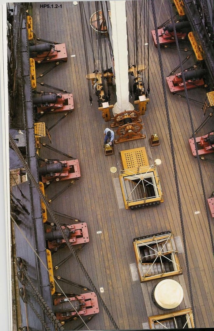
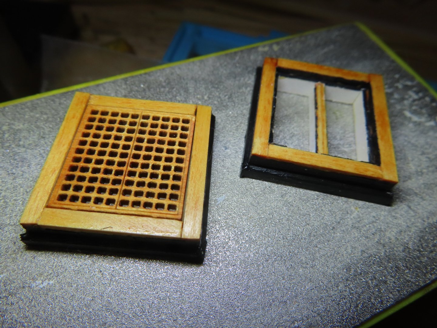
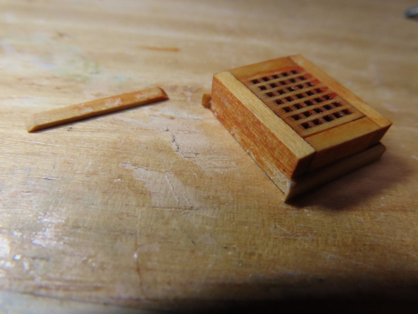
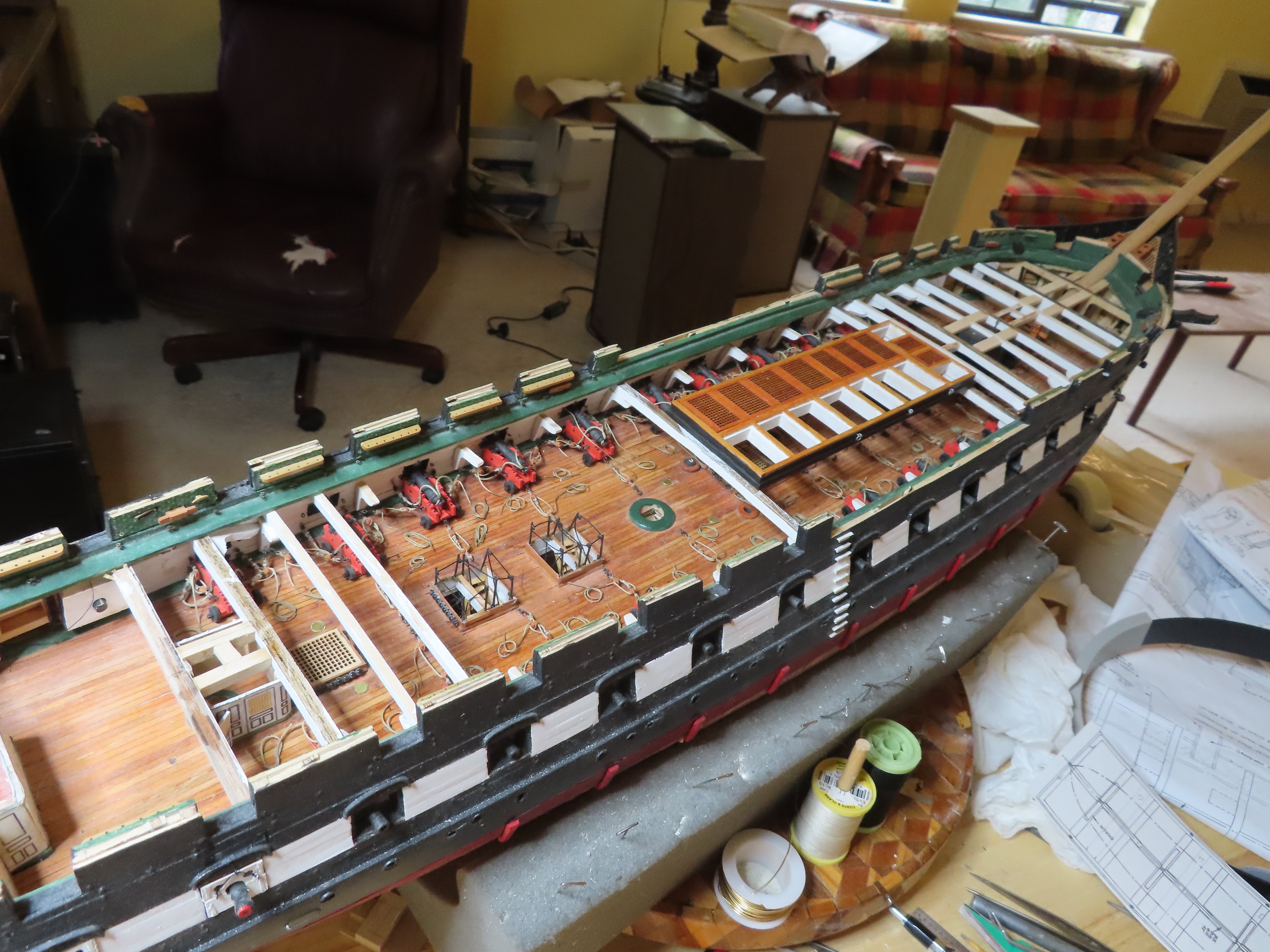
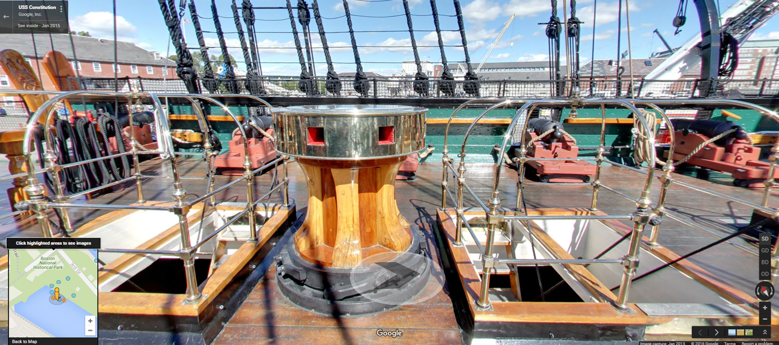
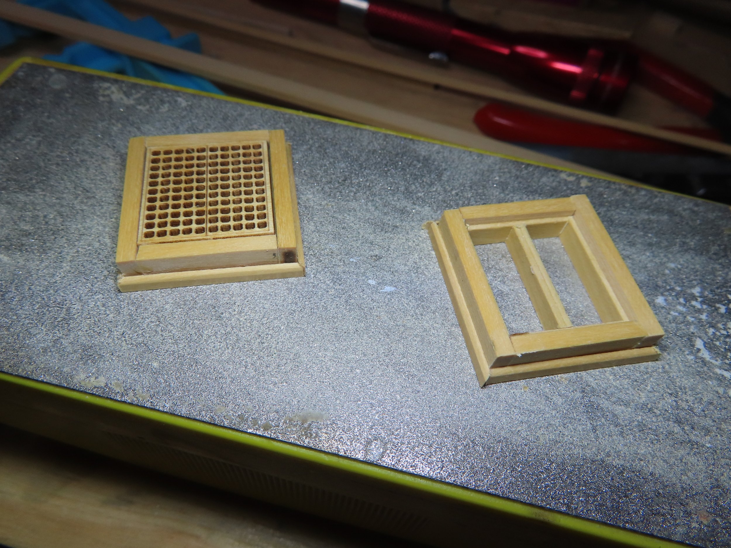
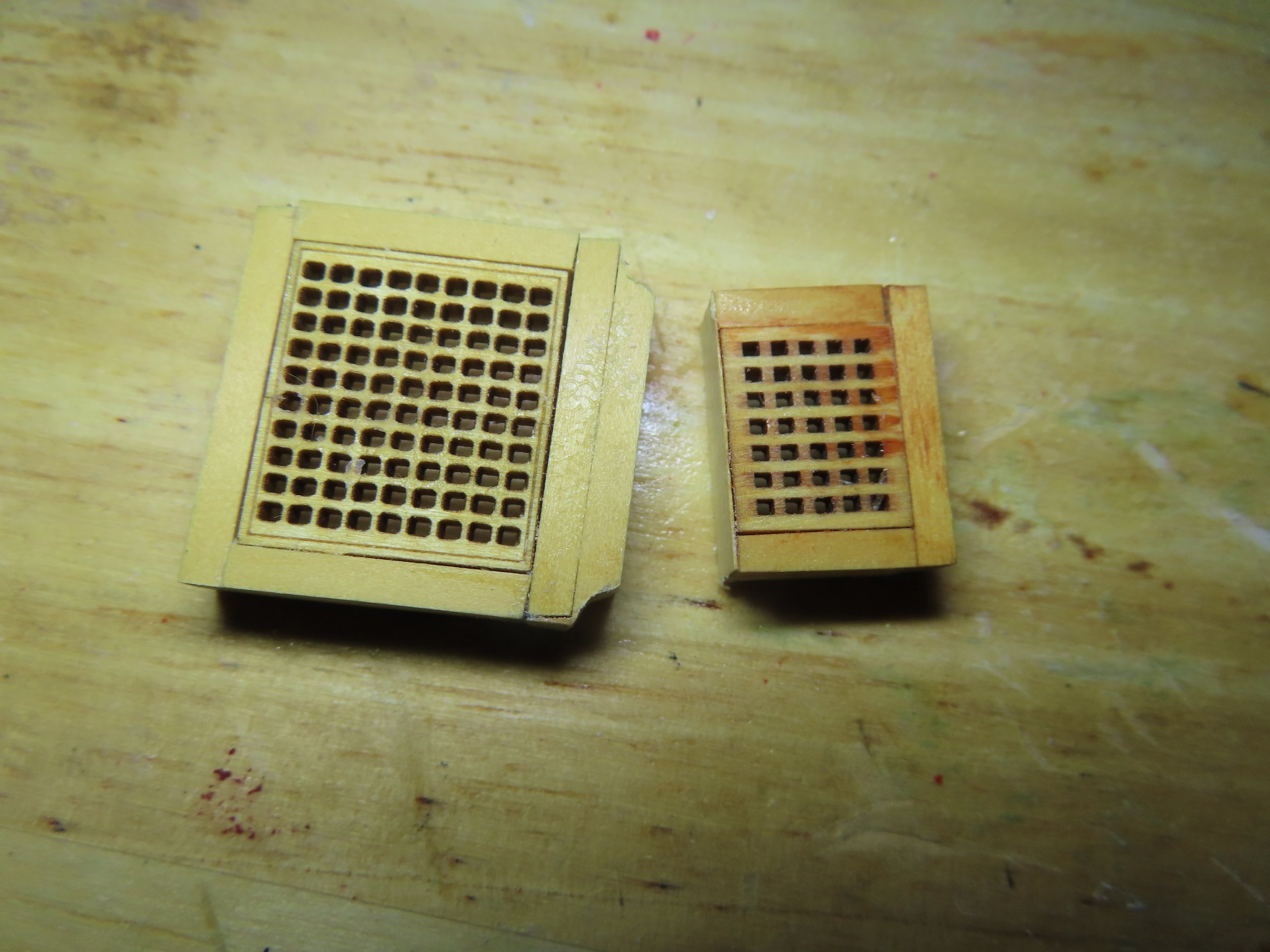
The last hatchways prior to the main one are on either side of the capstan. One hatchway is planned to be open, and the other closed. I found a small discrepancy with the kit gratings. If you look at the actual ship, there are separate gratings for each ladder, four in total. The kit provided two double wide gratings. Maybe they were this way in 1927 which is the main basis for the kit’s design, I don’t know. Whatever the case I’m leaving the closed hatchway as a double wide. The open one looks closely like, but not exactly like individual gratings. The main difference is the center beam between the ladders is flush with the top of the hatchway, whereas mine is sunk down to facilitate the formation of the lip which holds the grating should it me placed back on the frame. The image of the open hatchway is dry fitted pending painting.


- PaddyO, Unegawahya, Stevenleehills and 1 other
-
4
-
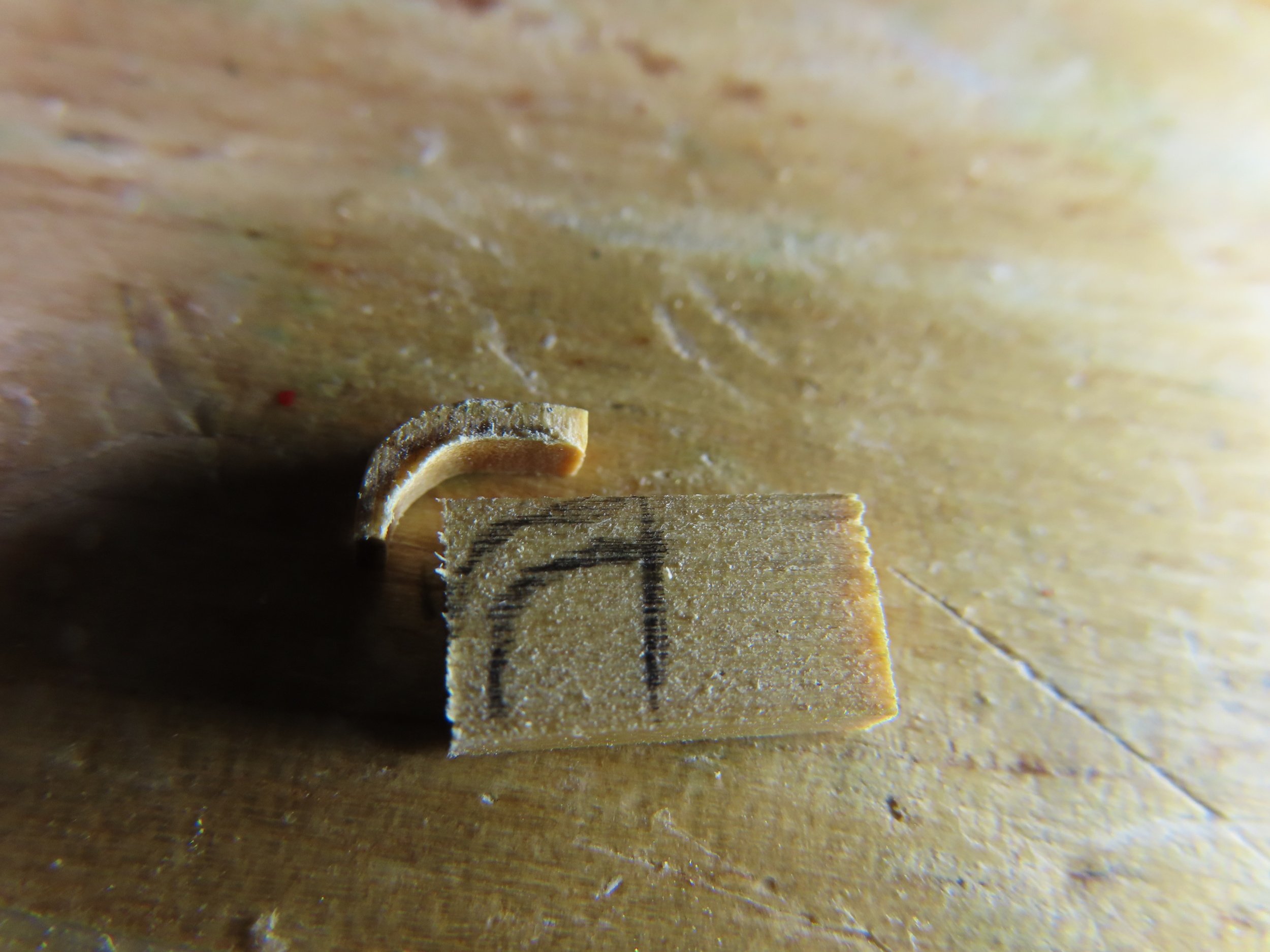
Now for the tricky part, the inside transition curve between the two grating frames. This curve was initially fabricated by trimming off the corners to start the transition. Then, using a router bit on my Dremel tool, the router bit allowed me to carve the inside curve of the 7/32” x 3/32” boxwood using the side of the bit as the cutting tool. This was done by hand, no drill stand or jig was used. To create the curved beveled edging was even tricker due to its size. I was trying to emulate a curved piece of beveled 3/32” x 1/32” boxwood because bending a strip of boxwood 90° in that short of distance was neigh impossible (for me at least). The curve was created by cutting a separate piece of boxwood to the basic shape and finished by carving by hand, again with the router bit fitted Dremel and assorted files. I suppose if I had a milling machine, it would have been more precise, but I think the results I got work just as well.


- Stevenleehills, usedtosail, mtbediz and 2 others
-
5
-
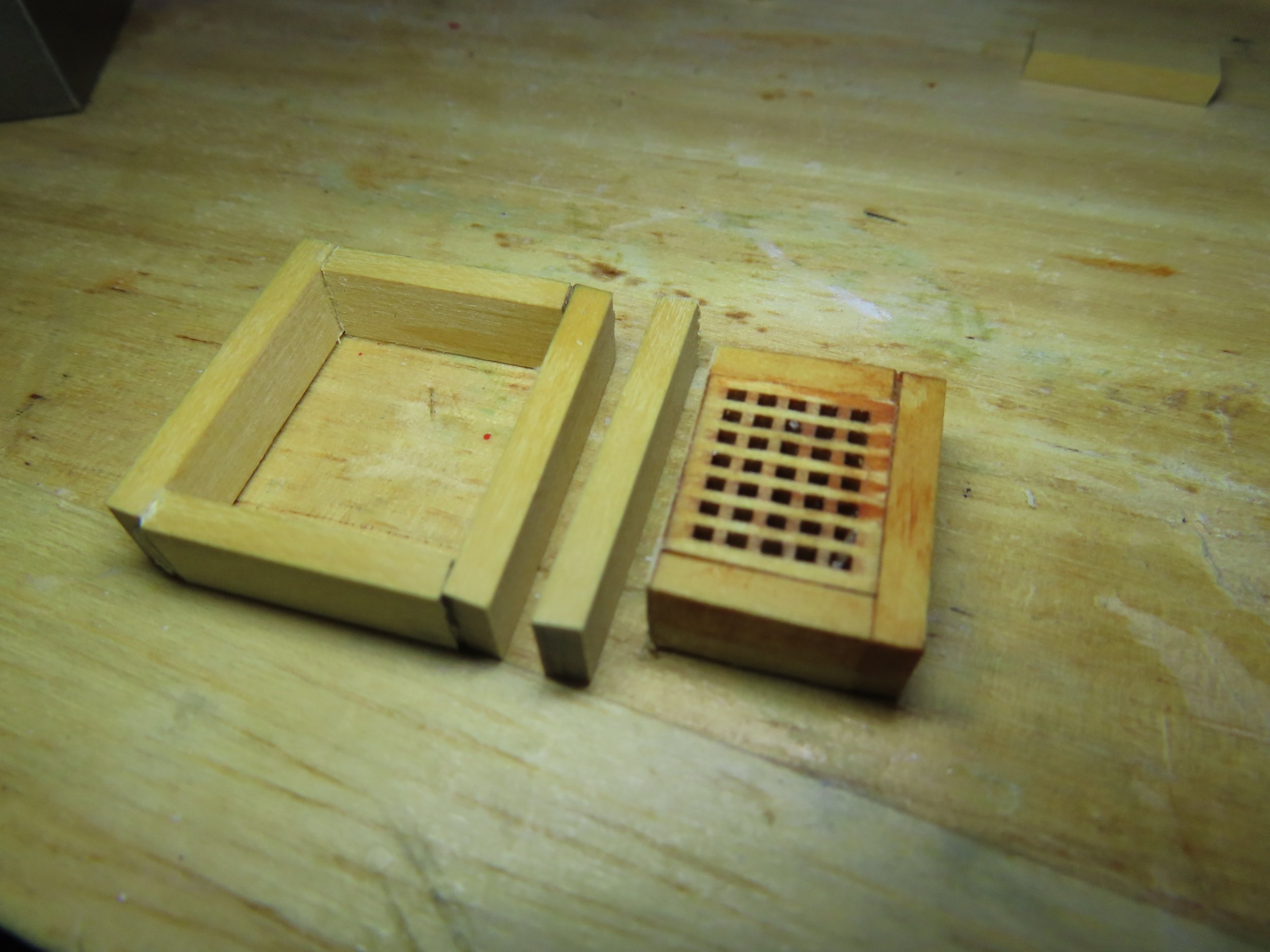
As it turns out, due to the construction of the ship’s wheel double grating, I was able to salvage most of what I had already made. First, I refabricated the foremast hatchway with the proper 7x6 grid grating. (Yeah, I know, no one will know the difference, but I and the man upstairs will). Using the old hatchway, now to become the smaller grating of the double hatchway, I removed all the 3/32” beveled edging from it as well as one wide side of grating 7/32” x 3/32” frame. This piece of the framework was replaced with another 7/32” x 3/32” (the length of the larger hatchway) that was glued to the larger grating frame. This is the piece that will act as the transition between the two gratings.

- Stevenleehills, Unegawahya and mtbediz
-
3


USS Constitution by Der Alte Rentner - Model Shipways - 1/76
in - Kit build logs for subjects built from 1751 - 1800
Posted
Very neat...nice job!!
Jon