


JSGerson
-
Posts
2,482 -
Joined
-
Last visited
Content Type
Profiles
Forums
Gallery
Events
Posts posted by JSGerson
-
-
-
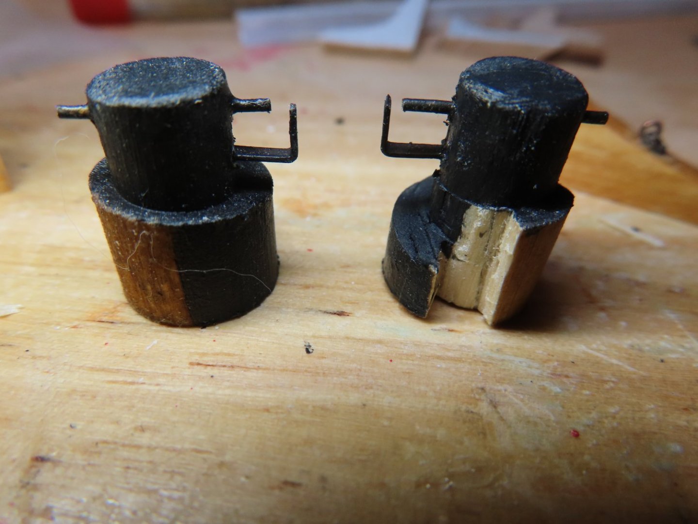
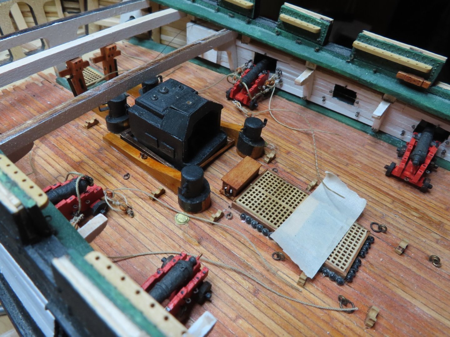
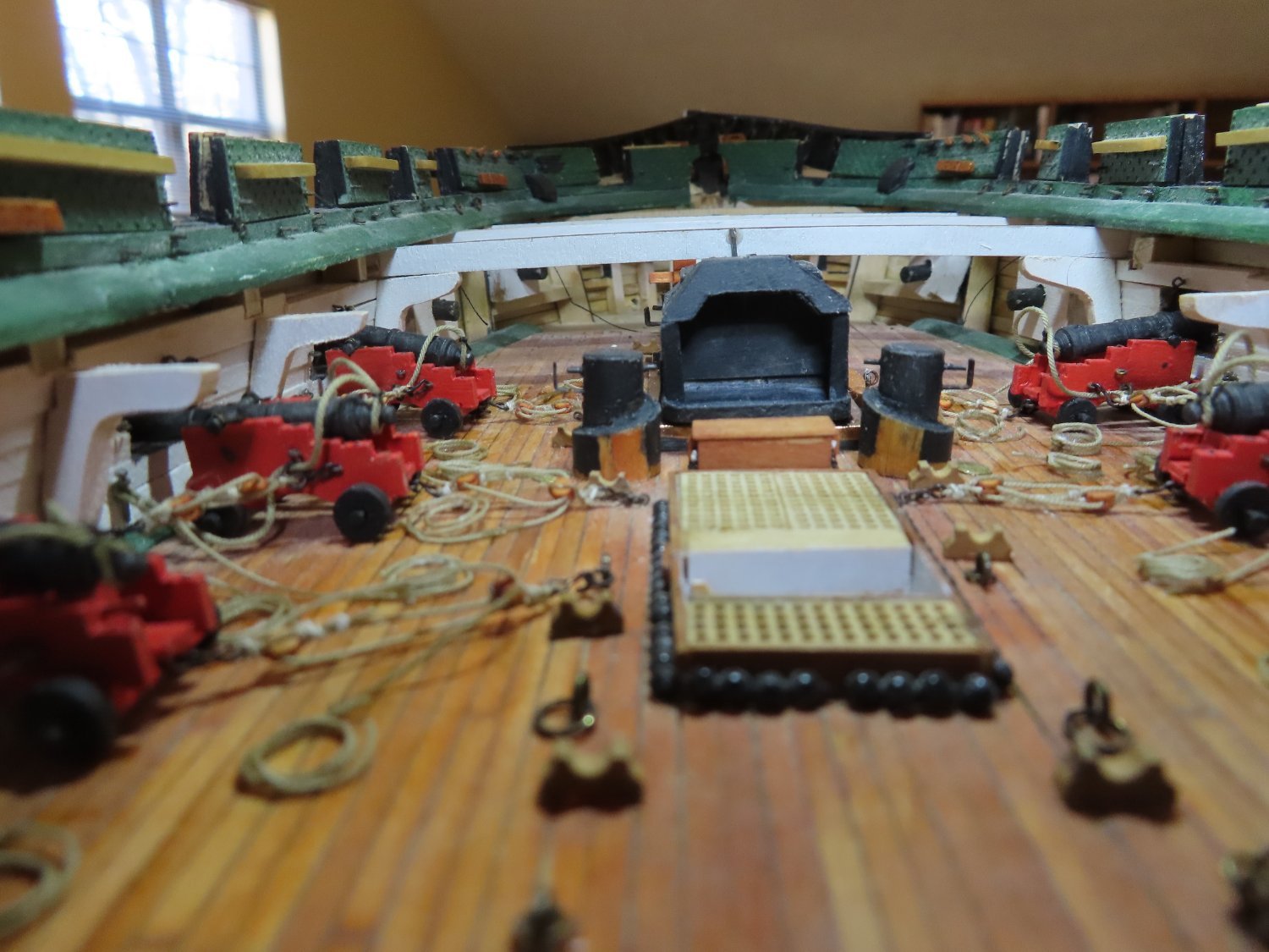
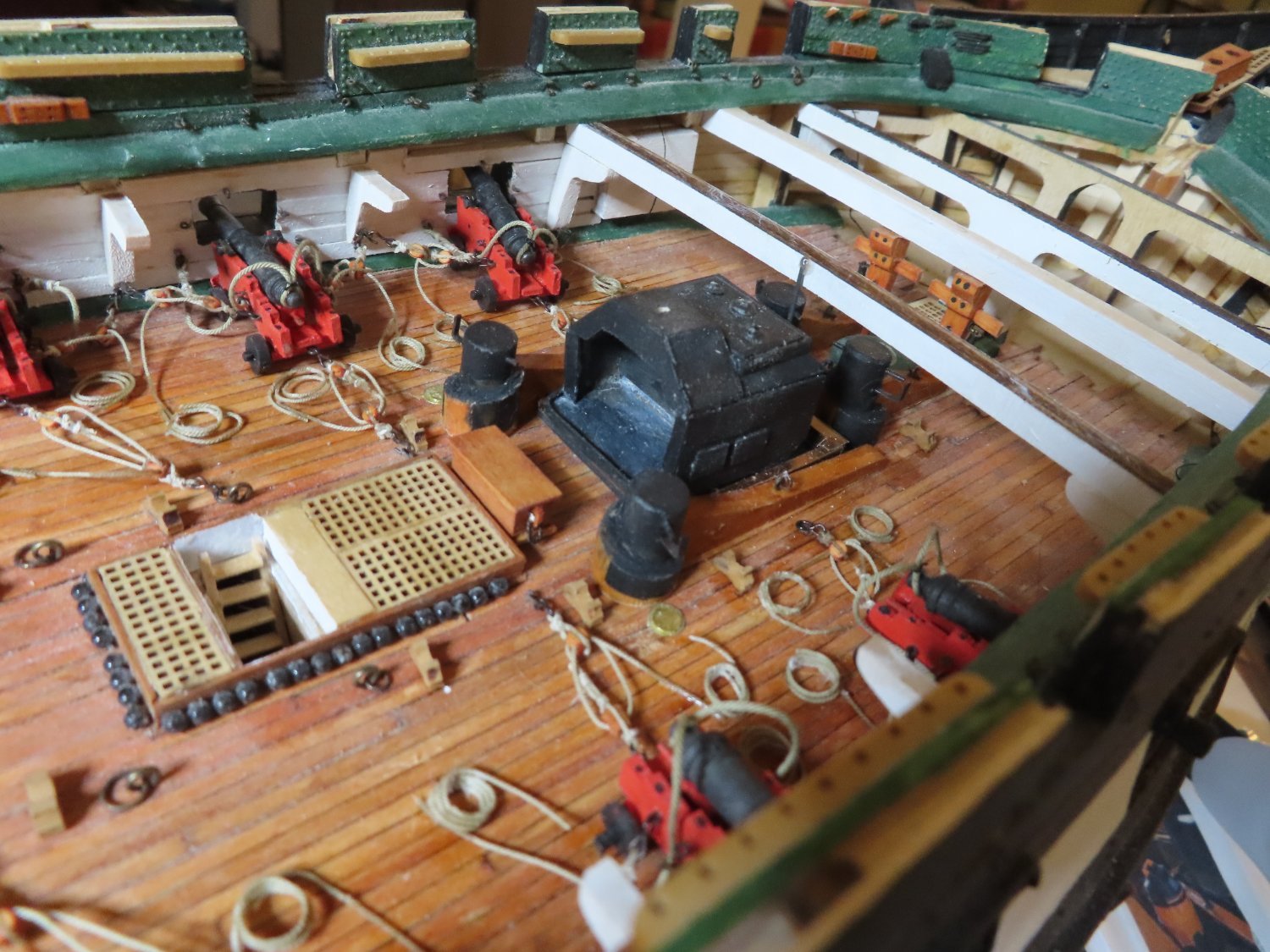
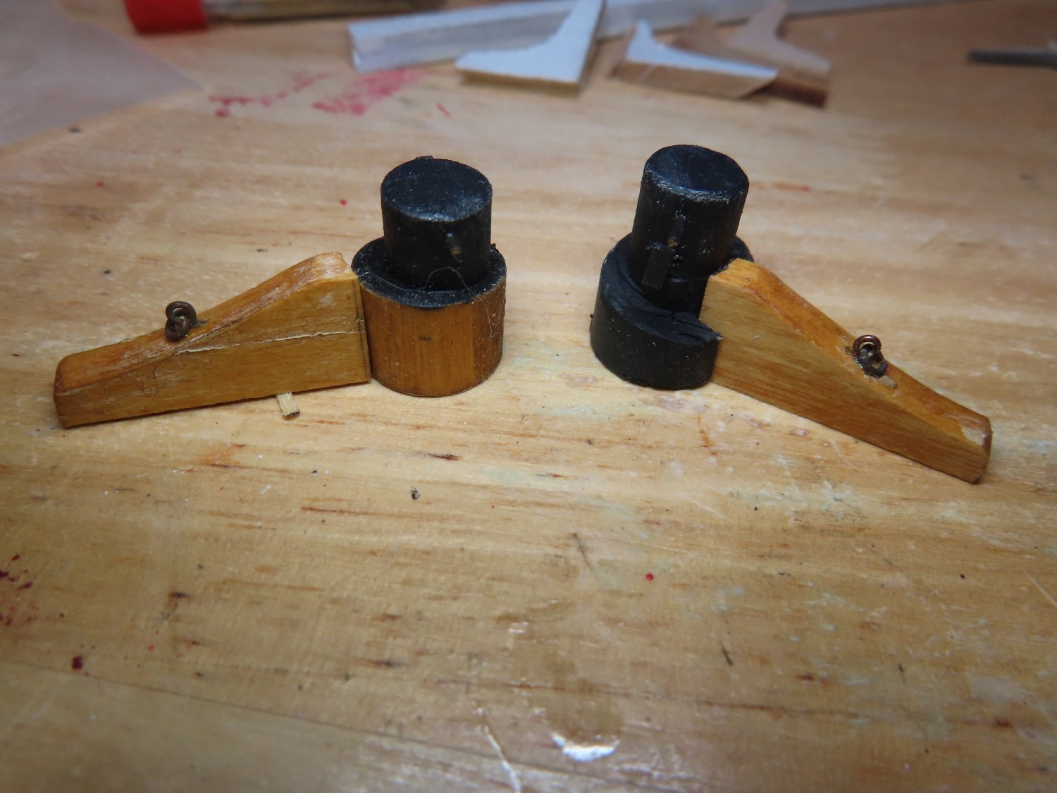
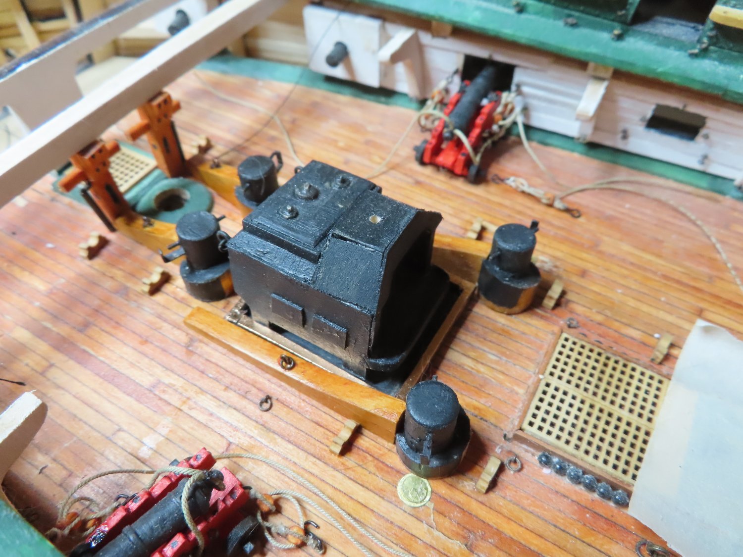
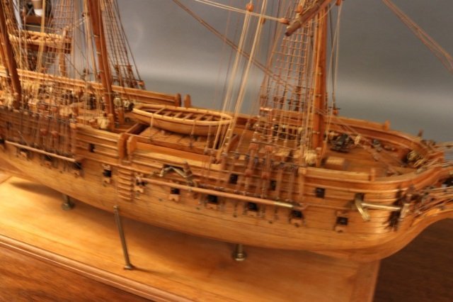
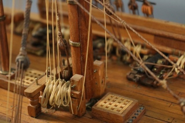
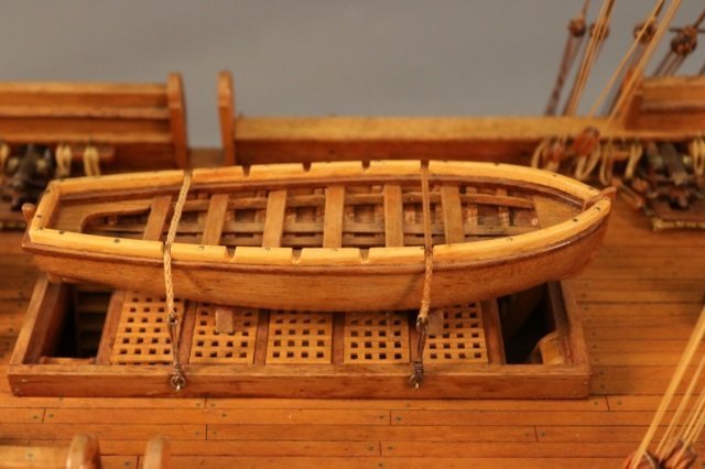
Then the next items to be installed were the anchor line bits and the stove with the stove tray which were previously fabricated. These were installed after dry fitting their final position and installing the spar deck beam that passes over the stove (not shown).


- Nirvana, Ryland Craze, SUBaron and 4 others
-
 7
7
-
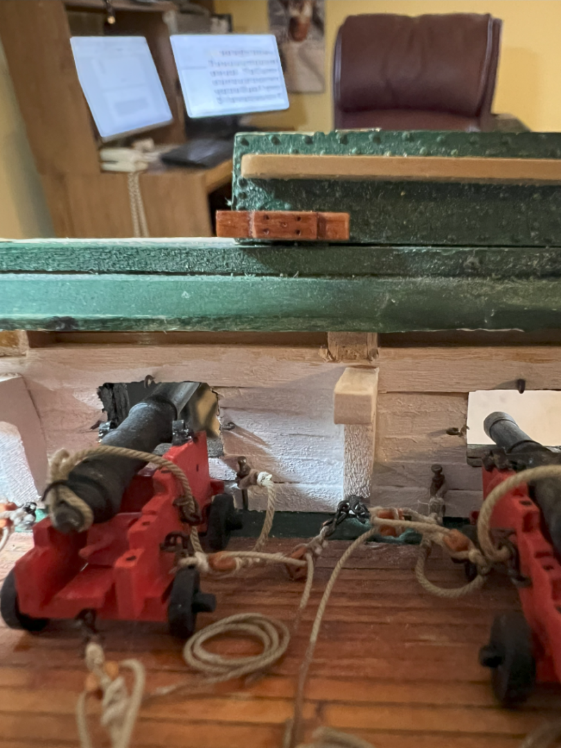
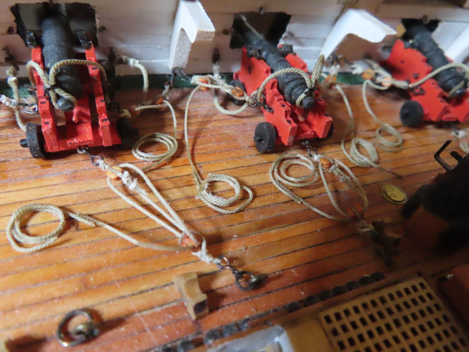
Moving aft, the gun rigs and recoil lines for three sets of guns after the dummy guns had to be fabricated. The three gun sets of fully rigged guns were glued into position with their recoil ropes secured to the bulwark with a small nail through two eyebolts. I initially planned to trim the nails so that they would be shorter and have a blunt end to more closely resemble the actual pin. This proved to be very difficult to use when attempting to thread them through the eyebolts and looped recoil rope. I just used the plain nail utilizing the pointed end to facilitate the installation to the bulwark. You would need a sharp eye to notice any difference.
- mtbediz, Nirvana, Geoff Matson and 5 others
-
8
-
If I remember correctly, Mr. Hunt planks one whole side, then does the other. I alternated back and forth every "band" in order to ensure my strakes mirrored each other.
Jon
- Geoff Matson, GGibson and mtbediz
-
3
-
Welcome aboard! Looks like you are off to a roaring start. I look forward to your future posts.
Jon
- mtbediz, SUBaron and Scottish Guy
-
3
-
You did an excellent job and you should feel proud of your workmanship. Just so you don't feel too bad, Ken Forman (xKen) is a professional model maker so he sets a pretty high bar to match. He designed the Model Shipways cross section kit of the USS Constitution, the Model Trailways Allerton Steam Fire Pumper, and written books on making brass models. So yeah, you did a fine job.
Jon
- Der Alte Rentner, woodartist, ERS Rich and 1 other
-
2
-
 1
1
-
 1
1
-
-
It looks like you learned a bit from my mistakes. I just didn't understand how all of these three dimensional surfaces merged together and ended up having to use wood filler. Nice job!
Jon
-
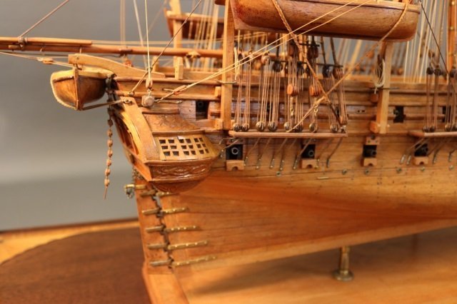
The photos came from post 83. I basically followed the practicum for the basic skeleton of the quarter galleries, then added my own touches. Basically everything went smoothly until I attempted the windows as you will see when you read my log.
Jon
-
Peter, you also need to look at post 199. Ken had to rip out the quarter gallery due to it being mis positioned.
Jon
-
I think you hit the color perfectly. Nice job!
Jon
- mgatrost, mtbediz, mort stoll and 1 other
-
4
-
-
Thanks Geoff, a very informative log! For those who do not want to search for the site, here is the link.
Jon
-
Quote
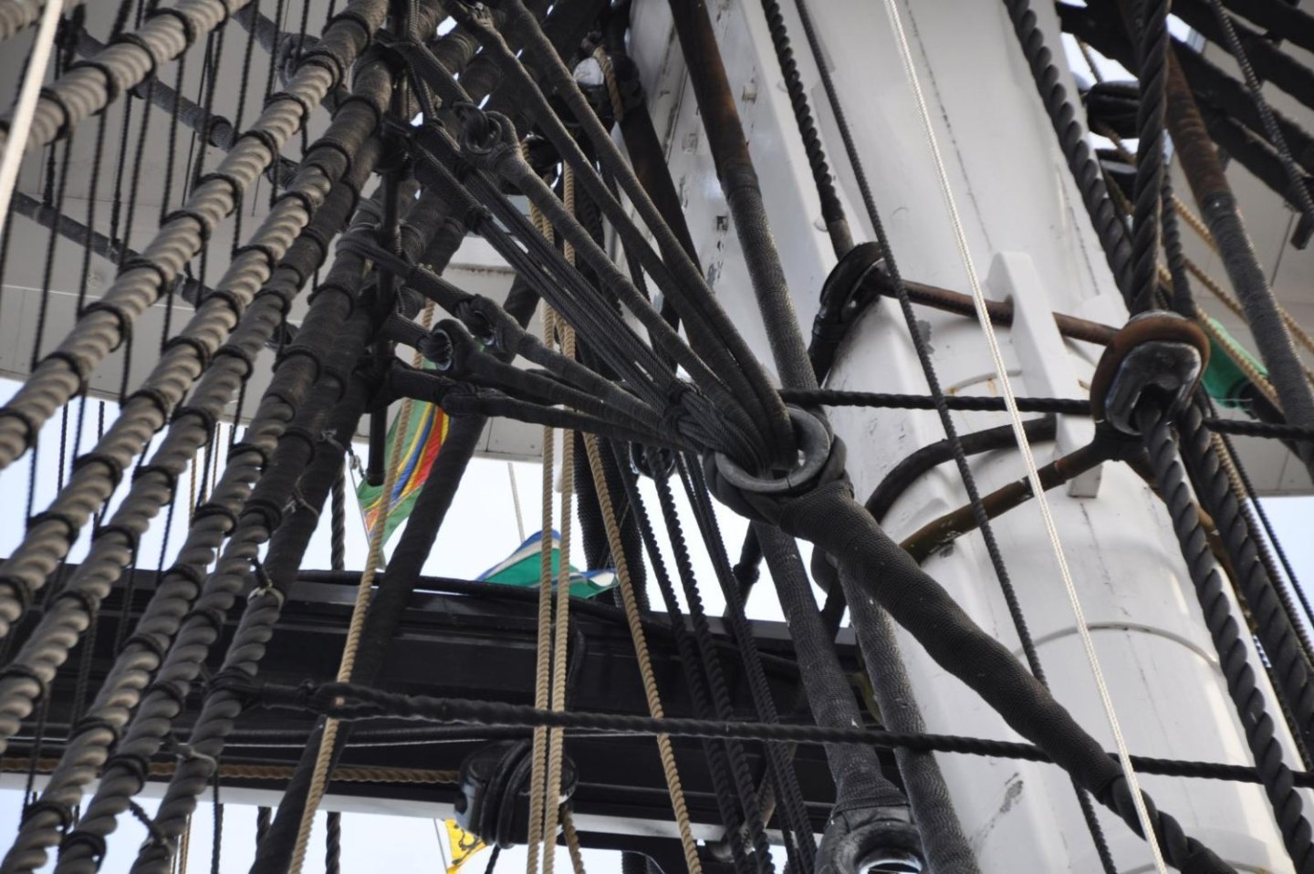
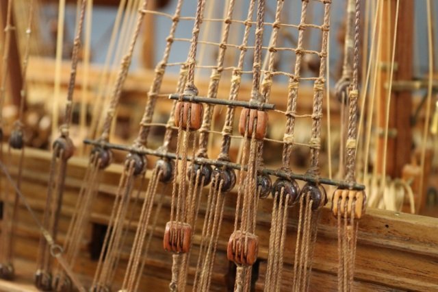
Geoff, although I have not got to the point of adding the futtocks and cartharpins I did find a good explanation of how to to them on Glenn-UK's build log for HMS Sphinx, starting at post # 281 for the lower ones and #367 for the upper ones.
You are doing a great job, keep up the good work.
Schooner, unfortunately you did not provide a link to the "Glenn-UK's build log for HMS Sphinx." I tried to locate it, but was unsuccessful. Would you be so kind as to indicate how to locate his build.
Thanks, Jon
-
I just found this "new" build log by Thrasher on Ships of Scale. He is dusting off a build that he's been working on and off for 10 years and is just starting the Bentinck shrouds. You might want to see what he is going to do.
Jon
-
-
Here are some photos that may (or not) help you.


-
DAR - Because the hull is going to be painted, I think I have a simple solution. On the subsequent strakes, increase the width a bit of a couple of planks in that area until the 'waviness" disappears. Add a little wood filler if needed and the smooth it out so the wood strakes blend and you can't see any creases. The paint will cover any evidence of the unevenness and it will disappear. Hope this helps.
Jon
- mtbediz and Der Alte Rentner
-
2
-
Wood filler was my best friend too!😁
-
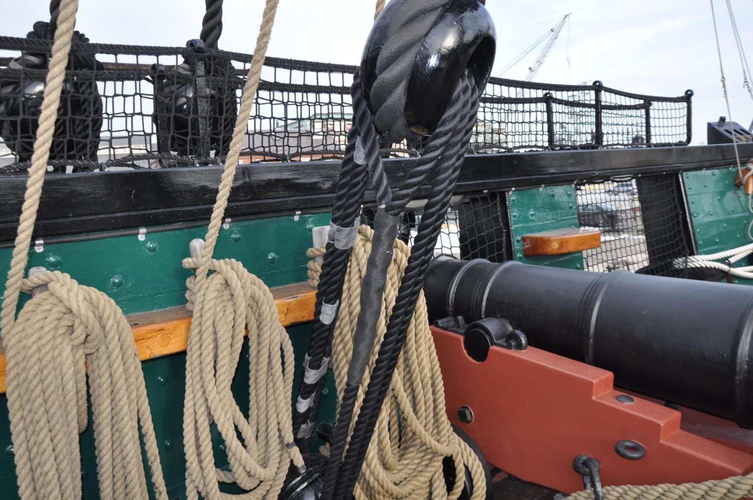
Just so you know for comparison, The MS kit provides 37mm long guns and 23mm carronades. How accurate they are to the actual guns at scale, I don't know. Speaking of guns, the actual ship does not have her original guns but replicas mostly installed in 1927. By 1897 on her 100th birthday, she no longer carried any guns. The carronades that most likely represented the ones used in the War of 1812 (an 1808 design) are the ones with a screw adjustment for raising and lowering the barrel. These replicas were installed in 1981. The ones using a wedge for that purpose are of the 1840 era and are more technically called gunnades. As I understand it, the idea is to eventually replace the gunnades with the more accurate carronades sometime in the future.
Just thought you might want to know, Jon.
- Ryland Craze and mtbediz
-
2
-
This is in essence how I planked my hull. A lot of “How to” articles and build logs use the tick mark method and proportional wheels or dividers. I just could not draw a pencil line on the hull that precise and get a strake to properly taper and fit. Like you I mathematically determined the width of the strake at every bulkhead point and sanded away, checking with the micrometer. I just didn’t do it with a nice spreadsheet. I worked each strake, one at a time, marked the determined widths on a piece of scrap paper. Once done, I discarded the paper. You did a fine job.
Jon
-
-
g8rfan - Actually, I have looked at HO figures, but I've never transformed a human figure's clothing/look into something that reasonably looked like someone else. I don't have that artistic talent; but it's not out of the realm of possibilities yet. I've got a long way to go before I'll could use them, so I still have time to consider other possible solutions. Thanks though, for the suggestion.
-
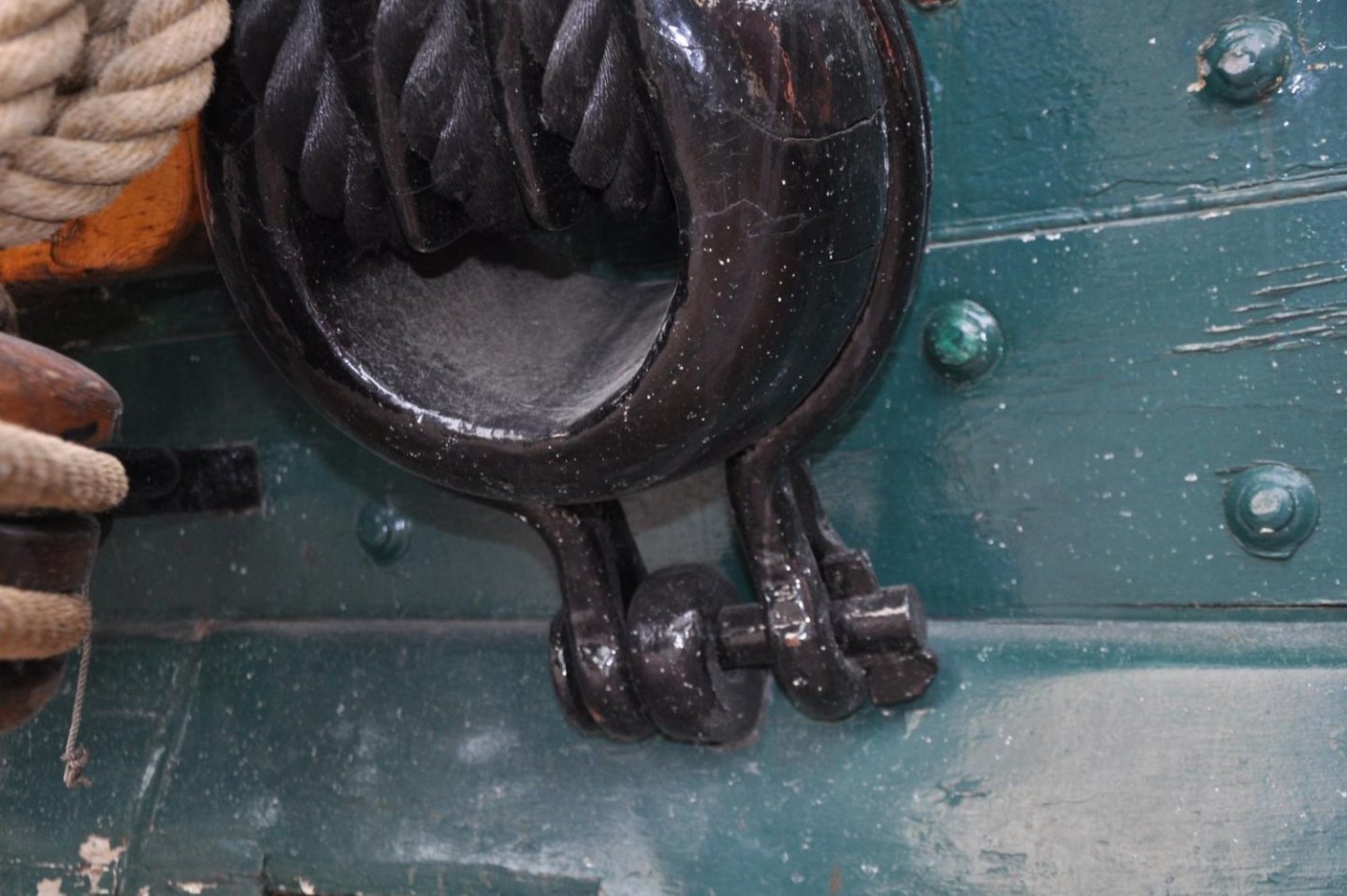
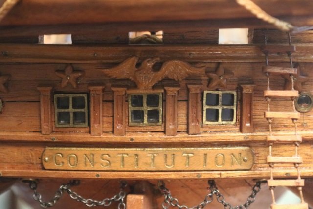
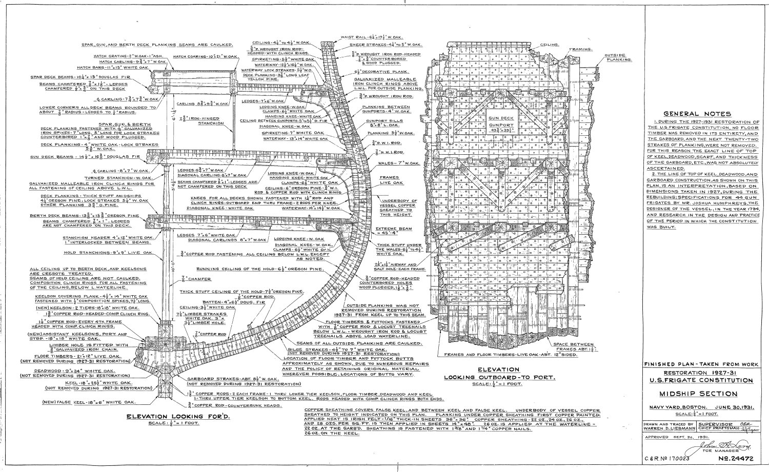
DAR, we may be both correct. I checked the US Navy plans and the wale does exist but is not as pronounced on the surface of the hull as the MS plans make it out to be. At best, the wale bumps out at its thickest point about 3.5" from the hull or about 3/64 at scale." and even that change is not as abrupt as the MS plans show. To see that fine detail in very old images is unlikely.

- Der Alte Rentner, Geoff Matson, mtbediz and 1 other
-
3
-
1


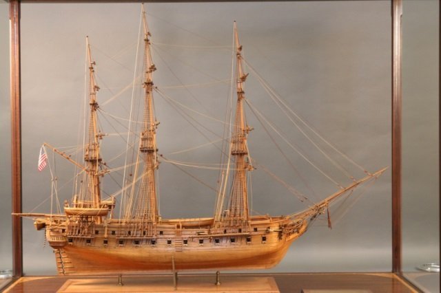


USS Constitution by JSGerson - Model Shipways Kit No. MS2040
in - Kit build logs for subjects built from 1751 - 1800
Posted
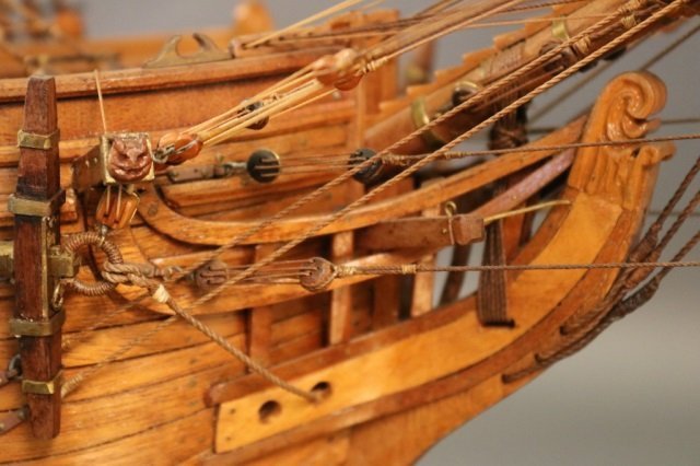
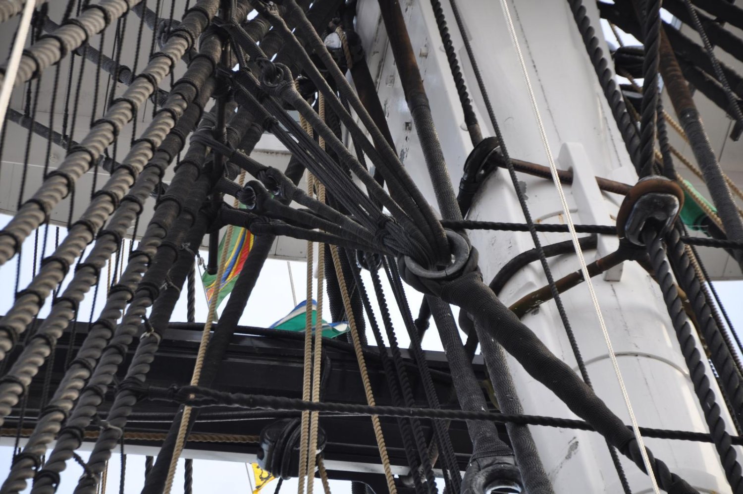
Finally, using the US Navy plan No. 022-06-2011 - Diagonal Rider & Knee Layout Revised 2011 (a minor revision of 27772, 1996) for the elevation view and No, 17636 Spar Deck Planking Removed 1926 for the plan view, I fabricated and added diagonal knees to the bulwarks around the gun ports of the rigged guns. Additionally, the three vertical stanchions around the stove were also fabricated from 0.032” music wire (for rigidity) and installed. Before I can move aft to the next section and while the gun deck is still accessible, I want to create spare deck structure to ensure the foremast will have a 3° rake when it is installed. As I have it presently planned, this portion of the spar deck is expected to be planked.IMG_1479.HEIC