


JSGerson
-
Posts
2,133 -
Joined
-
Last visited
Content Type
Profiles
Forums
Gallery
Events
Posts posted by JSGerson
-
-
-
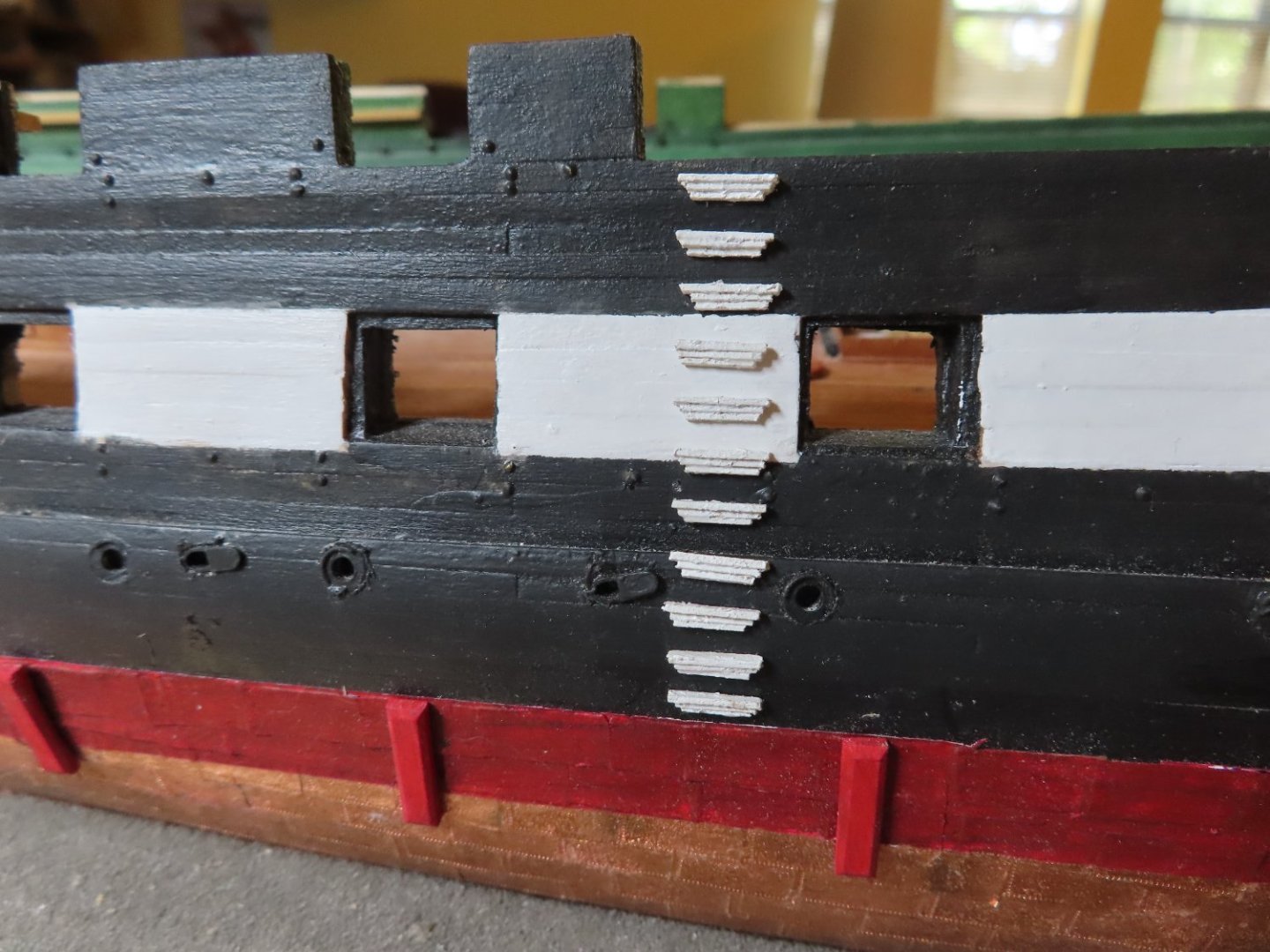
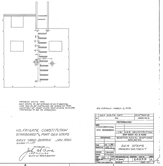
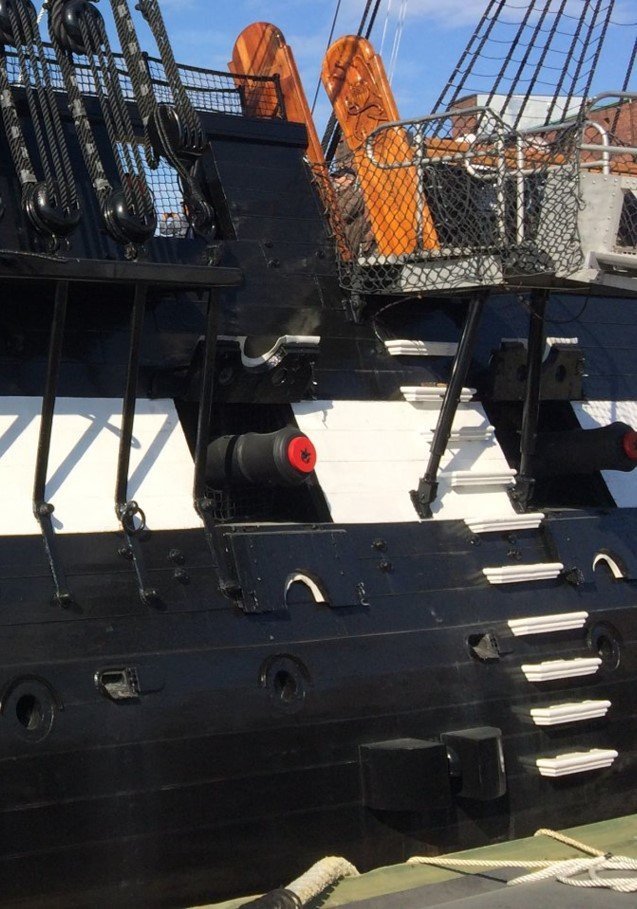
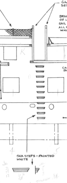
To make matters more confusing, although both the Kit’s plan and the US Navy show eleven steps, the US Navy plan shows seven of the steps are below the gun port while the kit shows only six. To clear this up I checked my photos, only to find the actual ship only has ten steps total. It did show, however, that there are only six steps below the gun port. I think the eleventh step was removed at the very top to allow for the visitor gangway to be installed.
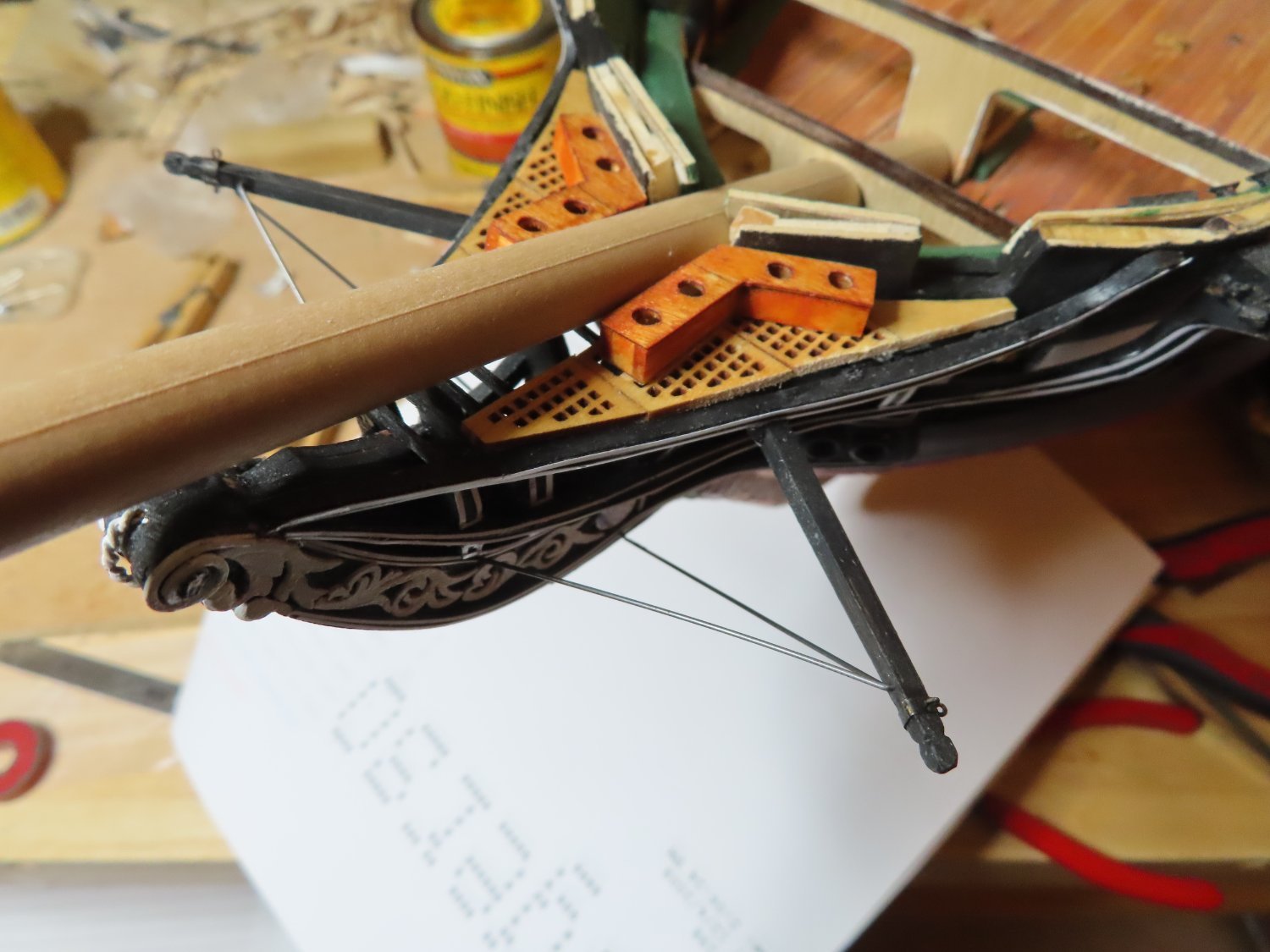
The step locations were marked by a piece of tape positioned on the hull which aligned the steps horizontally. A spacer block was used to ensure vertical spacing was consistent.
BTW, it’s been a week and I’m still waiting for the replacement rudder.

- Kirby, robdurant, histprof1066 and 3 others
-
 6
6
-
Comparing the US Navy plan No. 24999001 vs the kit’s, I noticed that the steps on the kit’s plan drop vertically straight down while the US Navy plan, six steps skew diagonally forward a maximum of 6.5” or 5/64” scale. The reason for the skew is there is a scupper cover the steps are avoiding. As it turned out, I did have the scupper located where it should be but did not have to make any adjustment that the eye could perceive.
-
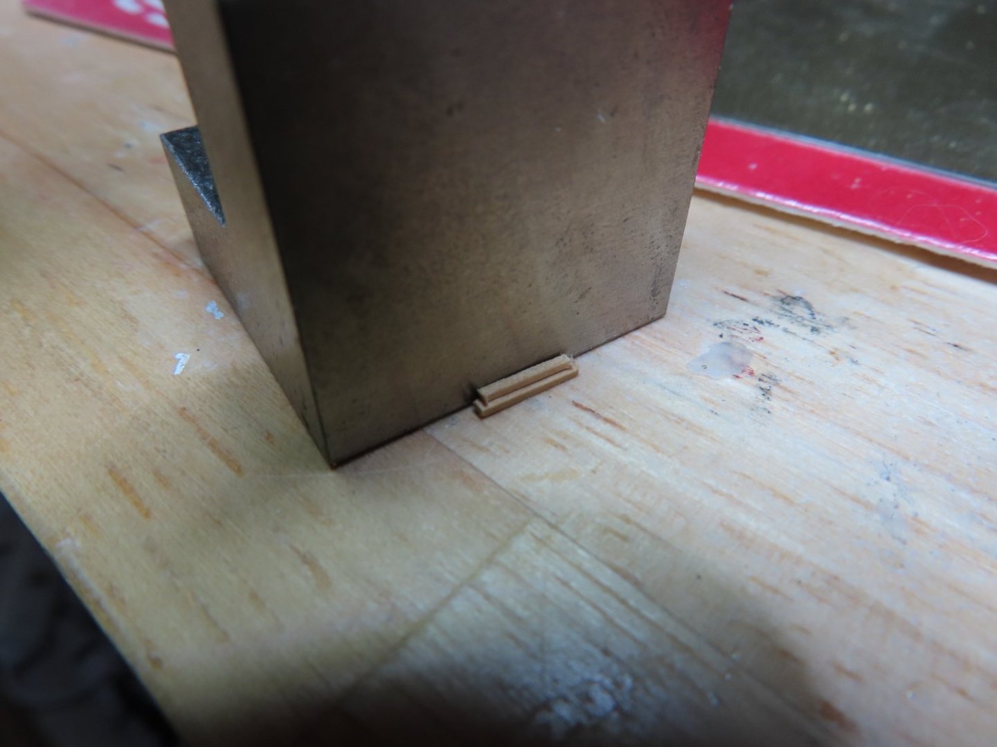
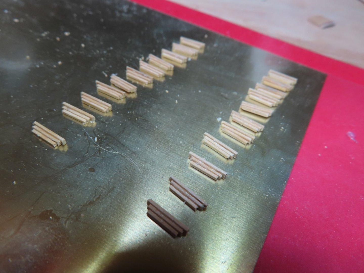
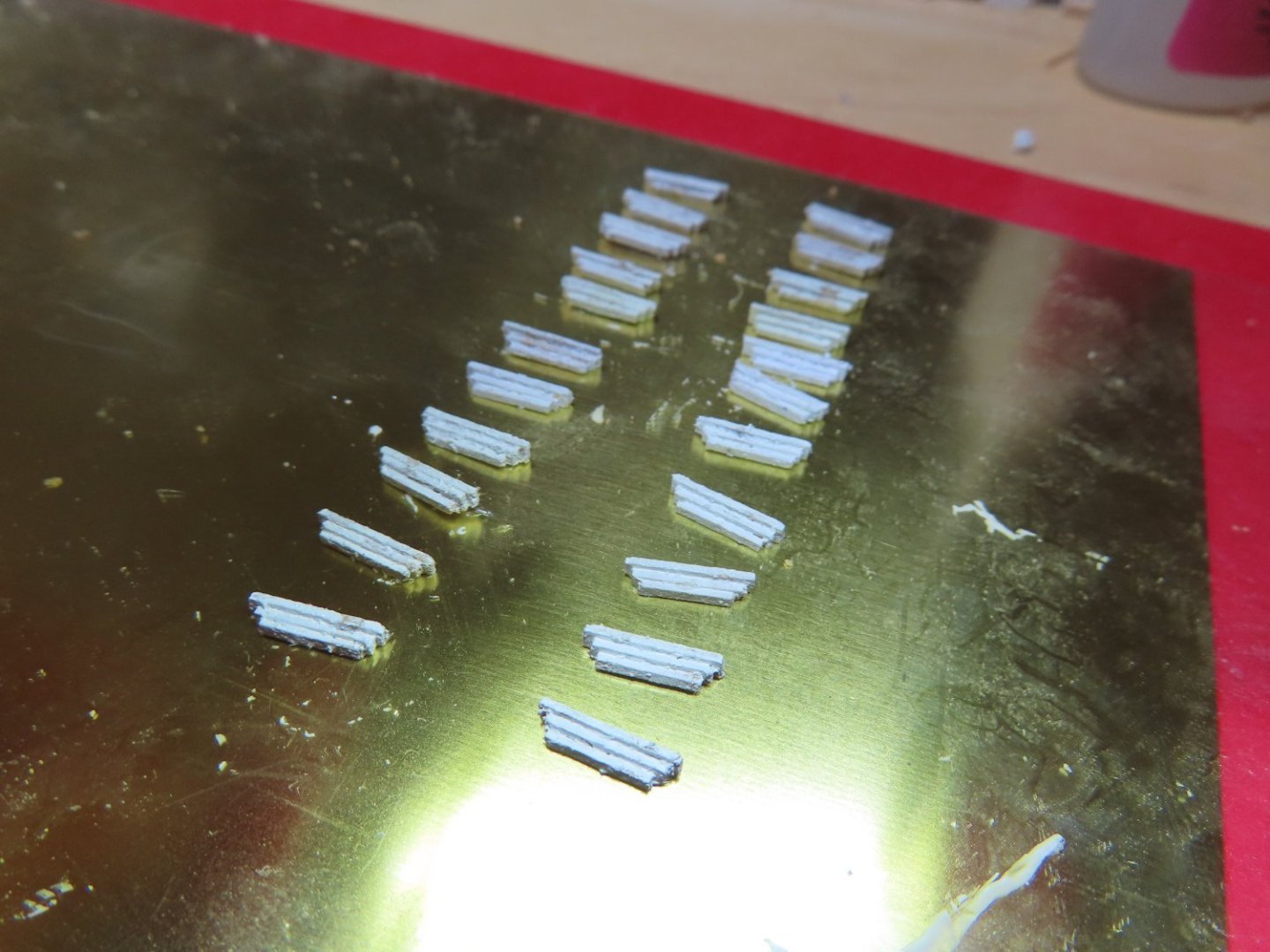
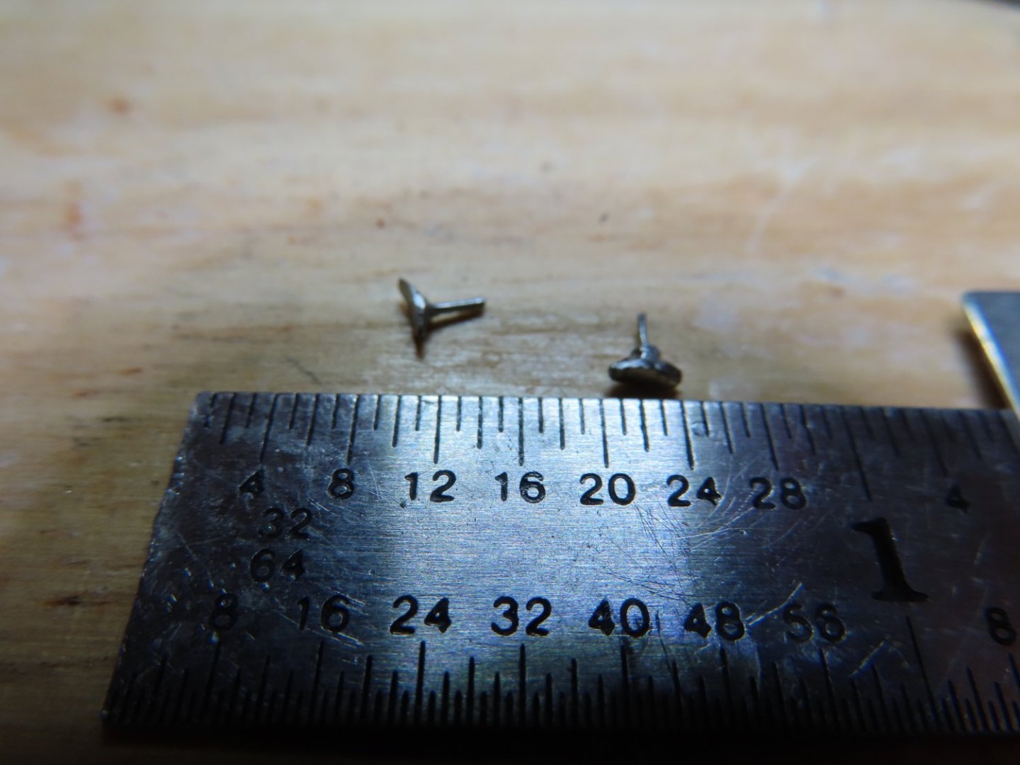
Using a 1” right angle block, the pieces were glued into a pyramid stack. I used very tiny drops of white glue which allowed me to position and adjust the pieces into position before the glue set. I would have made a mess with CA glue. The steps were then painted white with a couple thin coats so I wouldn’t lose the pyramid details in the steps. Everything was painted except for the side that was going to be glued to the hull.
-
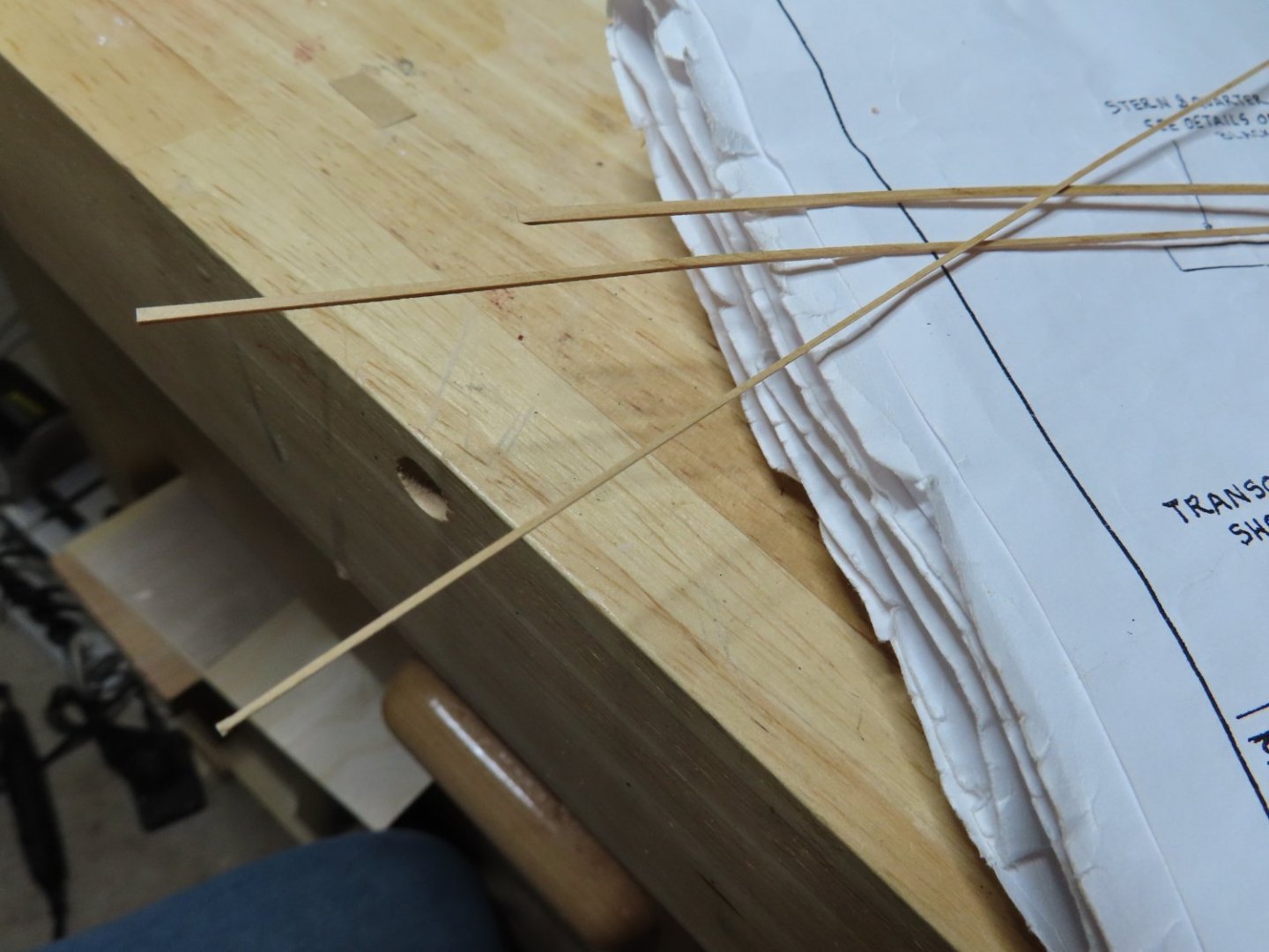
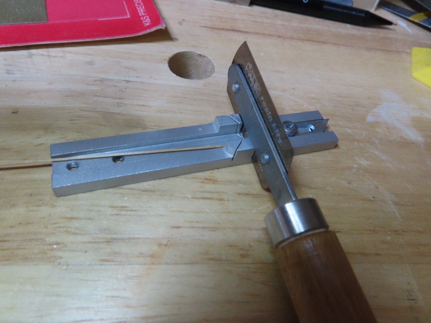
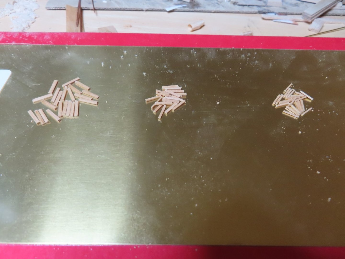
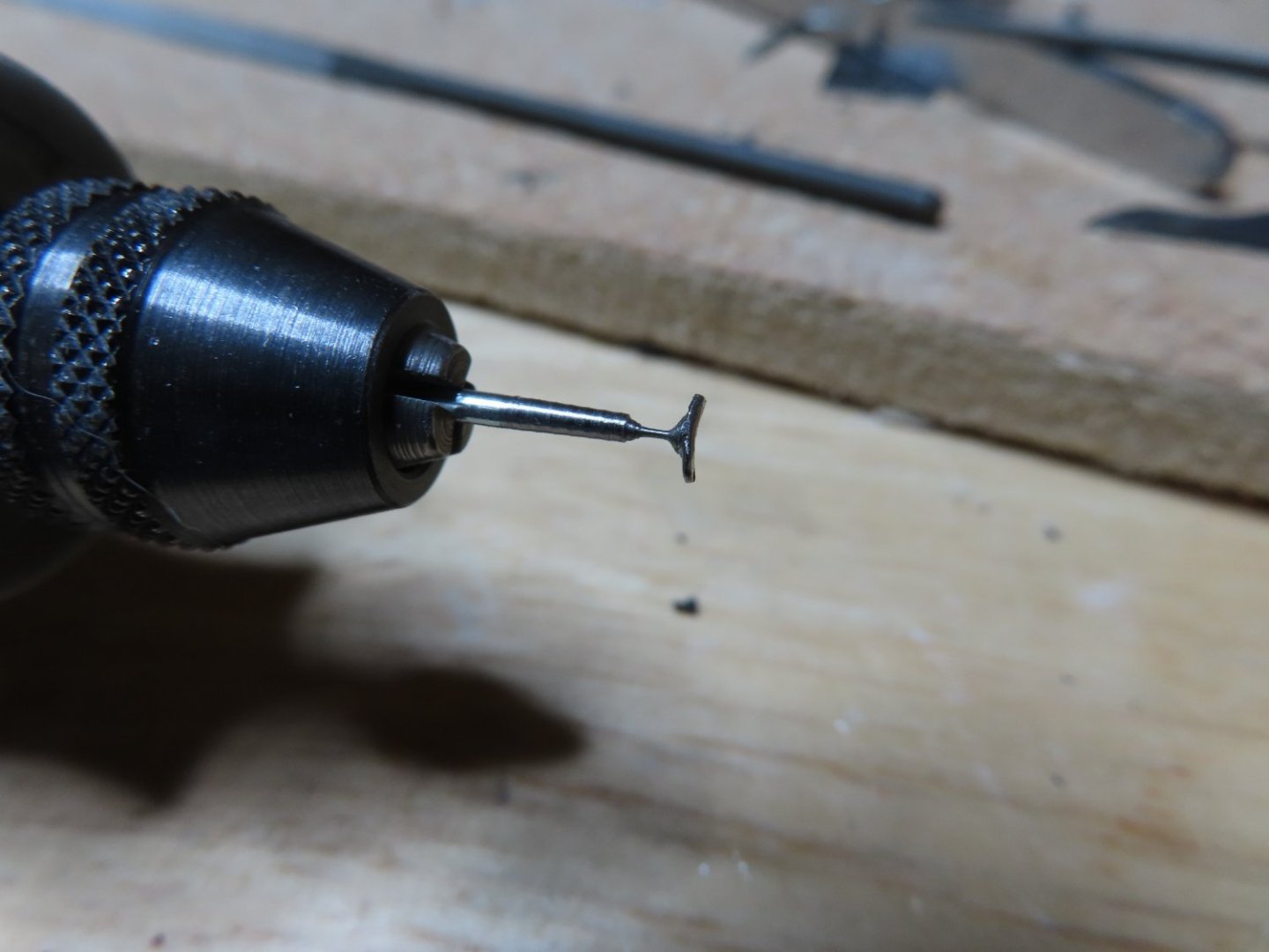
The practicum uses styrene as the material of choice. I chose to use wood instead of plastic. I used boxwood because it doesn’t splinter apart when cut to short narrow pieces and it can hold an edge. I used my Byrnes saw to cut a 3/8” wide strip, 1/64” thick from some stock material. Then I cut the strip into 5/64”, 4/64”, and 3/64” length strips. These strips were then cut again to 21/64”, 19/64”, and 17/64” length pieces respectively using my micro miter and razor saw.
-
Sea Steps
The kit plans indicate there are eleven sea steps on each side of the hull, climbing from the water line up to the spar deck. Each step is comprised of an upside down, three-piece, four-sided pyramid. Three sides step outwards by 1/64” per tier on the edges while the fourth side is flush with and is attached to the hull. Surprisingly, there very few images of the sea steps with detail. This one will have to do.
-
I too had these issues with the copper plating. If I were to do it over again, I would have applies a couple more coats of polyurethane on the hull to make it as smooth and glass-like finish as possible. Embossing the surface of the copper tape to simulate nail dimples reduces the contact area of the tape somewhat so it needs that extra smooth surface for adhesion..
I made a CA applicator out of a medium sized sewing needle by cutting off the end of the eye creating a two prong fork. I then added a long thin wooden handle by drilling a hole into a piece of wood and inserting the point of the needle into it. I didn't glue it, but just pushed it in hard. This allowed me to switch out the needle with a new one when needed. Cleaning the open eye is done with a butane cigarette lighter. The excess CA burns off real quick.
I had to constantly apply CA glue to various areas of copper plating over the course of its installation as it took time for the weak adhering plates to reveal themselves. It was a pain to constantly do this. In the end, I got the effect I wanted.
Jon
-
I just discovered your build log today and admired your workmanship. I built the Mamoli Rattlesnake in 2017 as my first square rigged wooden ship using Robert Hunt's practicum as my bible. I could not have built my model without it. The build was a kit bash adding all kinds of details the kit did not have. and was a challenge for me as a first time builder, but I think it was worth it. The Rattlesnake is a beautiful ship. I look forward to your future posts.
Jonathan
-
Congratulations on a job well done!
- Dave_E, Knocklouder, Kenneth Powell and 1 other
-
3
-
 1
1
-
I have high praise for Model Expo as well. It costs them money to replace parts and they don't charge for shipping which is amazing.
-
WTF
I had expected that my next post would be the fabrication and installation of the rudder hinges. Since my last post, I have fabricated the gudgeons and was about to install them onto the hull. To do that, I was going to use the rudder I finished last August, to mark the positions of the hinge and gudgeons on the hull so they would align with the rudder pintles. There was only one teeny, weeny, little problem. My rudder has vanished! It wasn’t in the box I thought I put it in. I’m pretty good at finding tiny bits of stuff I drop on the rug in my work area. I swear that rug eats anything, and things don’t bounce on it in a logical manner. Yet, I manage to find what I’m looking for (most of the time) given enough motivation. This is a painted and copper plated object about 5” x 1” x 3/16” and I can’t find it after two days of searching!
There is no one else in my house as I am a lifelong bachelor except for my 14-year-old cat who grazes on her food throughout the day when she is not sleeping or asking for affection. She has never ever touched any of my model stuff in her life, but even so, I did check under the furniture in the whole room just in case. Nothing. It appears it has vanished to the realm of missing socks or some such place.
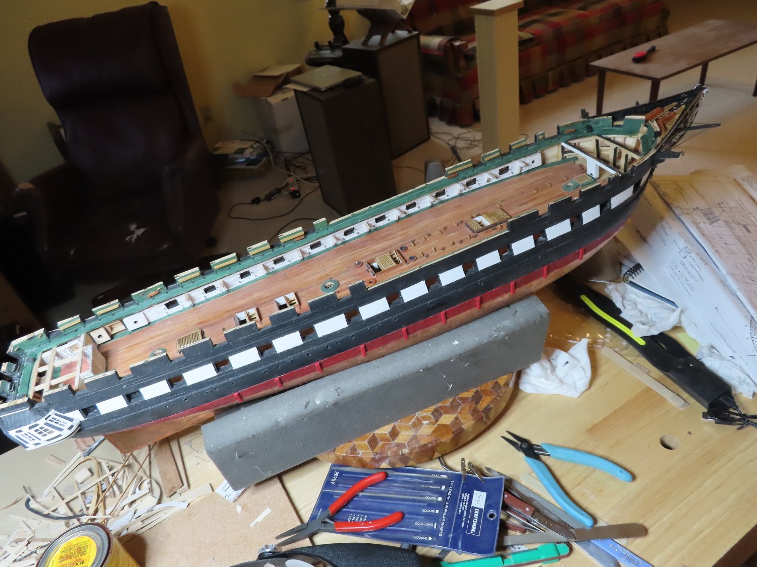
I do know of one method of finding it, and I’m afraid I am going to use it. All I must do is fabricate a new one. Once I’ve done that, the original one will miraculously reappear. So, today I reluctantly ordered a replacement part from Model Expo. In the meantime, to keep working on the model, I plan to work on the sea steps. I will post my progress with that then post what I have already done on the rudder hinges to keep the processes coherent for the readers. We’ll see what happens.
-
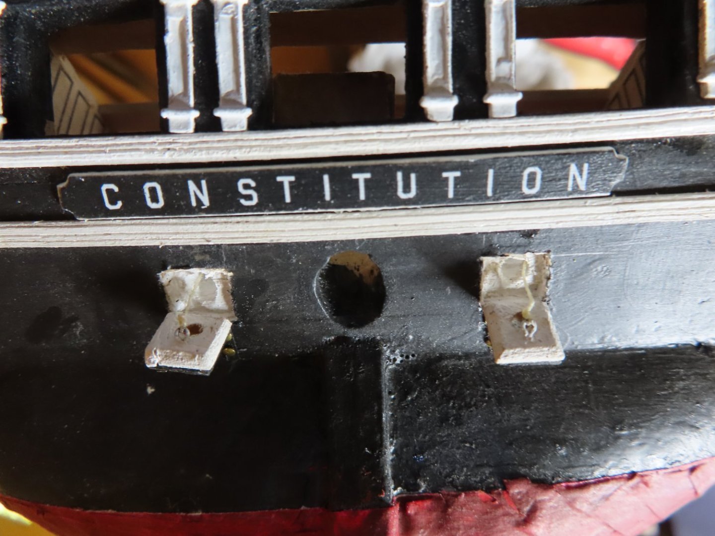
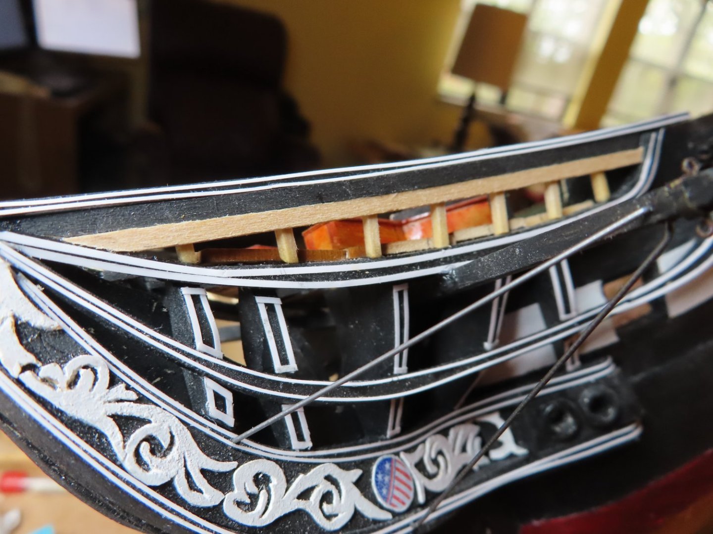
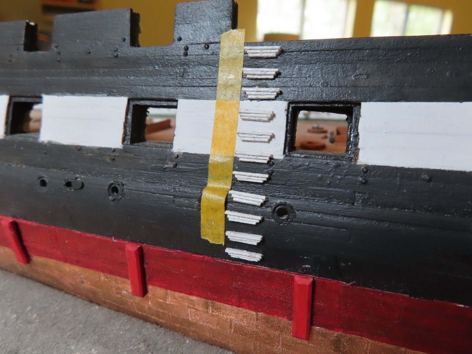
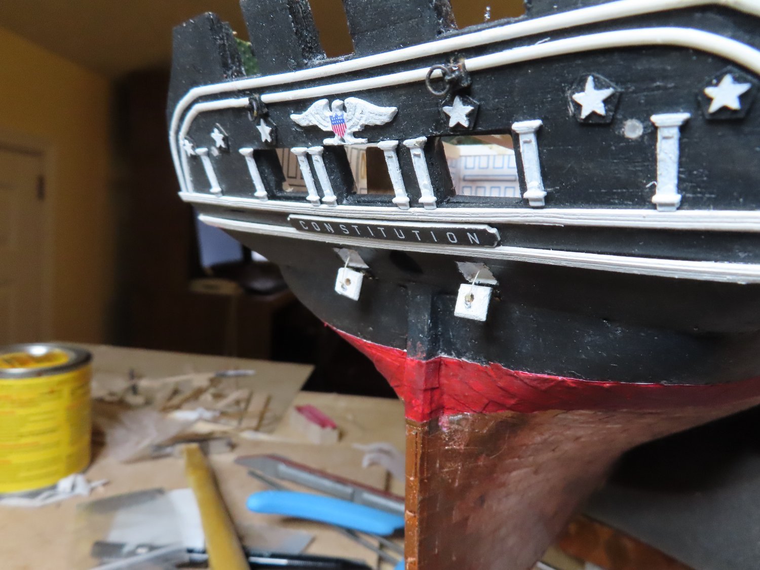
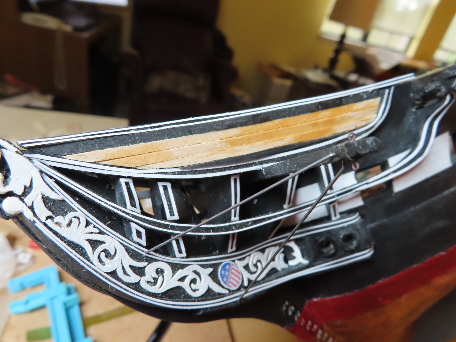
The last step was to add eyebolts on the inside face of the doors for the pull cord that opens and closes the door. Plain sewing thread was used. One end tied to the eyebolt and the other loose. Once the thread was stiffed with CA glue, the loose end was inserted into the round tunnel after the port doors were nailed to the transom. The stiffened thread looks taught, and no one can see it’s not secured to the inside the hull. The doors were positioned by bending the hinges, so they hung perfectly vertical.

-
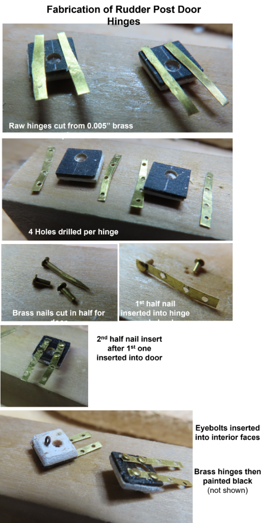
The kit provided photoetched hinges which were not suitable for my purposes:
· The hinges on the actual ship extend the whole vertical length of the port door and over to the transom below the port opening. The kit’s photo-etched hinges are the same hinges to be used on the gun ports. Those are half of the hinge. The other half would be fastened to the inside the gun port opening.
· I needed physical support for the doors. Because there is so little glueable surface area on the hinges, actual nails were required to secure the hinges to port doors and transom face.
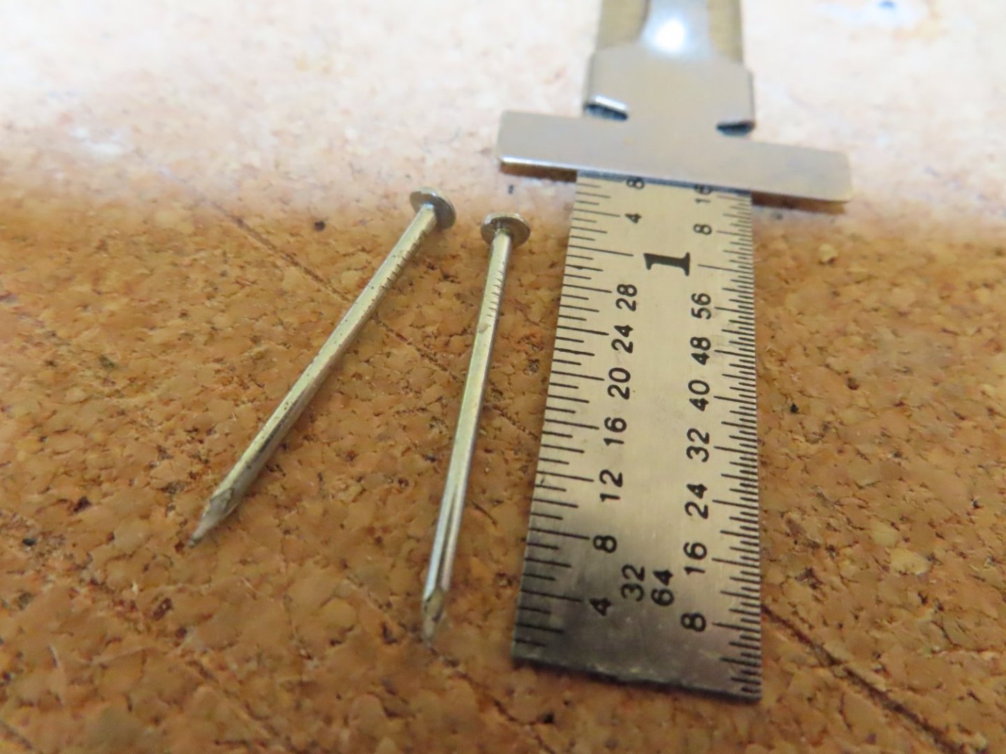
With a pair of small scissors, four 1/16 strips of 0.005” brass plate were cut to size; the vertical length of the door plus the extension to attach to the transom. Two pieces per door were required.
Four holes were drilled into the hinges with a #69 bit to accept the small brass nails for each hinge. Two nails to go into the door and two nails to go into the transom. The brass nails for the port door had to be cut in half because their length was longer than the thickness of the doors. Getting the brass nails through the hinge and into the meat of the door was a little tricky.
1. Locate the position of the first nail and mark it with a pin indentation.
2. Drill the hole using the pin indentation to start the drill, to a sufficient depth to accept the nail.
3. CA glue the half nail in the first hole on the hinge.
4. Place the hinge with the half nail into the drilled hole in the door. This positions the second hole.
5. Drill the second hole in the port door through the hole in the hinge.
6. Insert the second half nail into the second hole.
7. CA glue the nails and hinges
8. Repeat for the remaining hinges
Once all the brass nails were inserted into the port door, the hinges were painted black as well as any required painting re-touches. You may have noticed that the nail heads appear to out of scale with the hinges. This couldn’t be helped as I had no other smaller brass nails. No mater though, they won’t be seen in the final assembly.
-
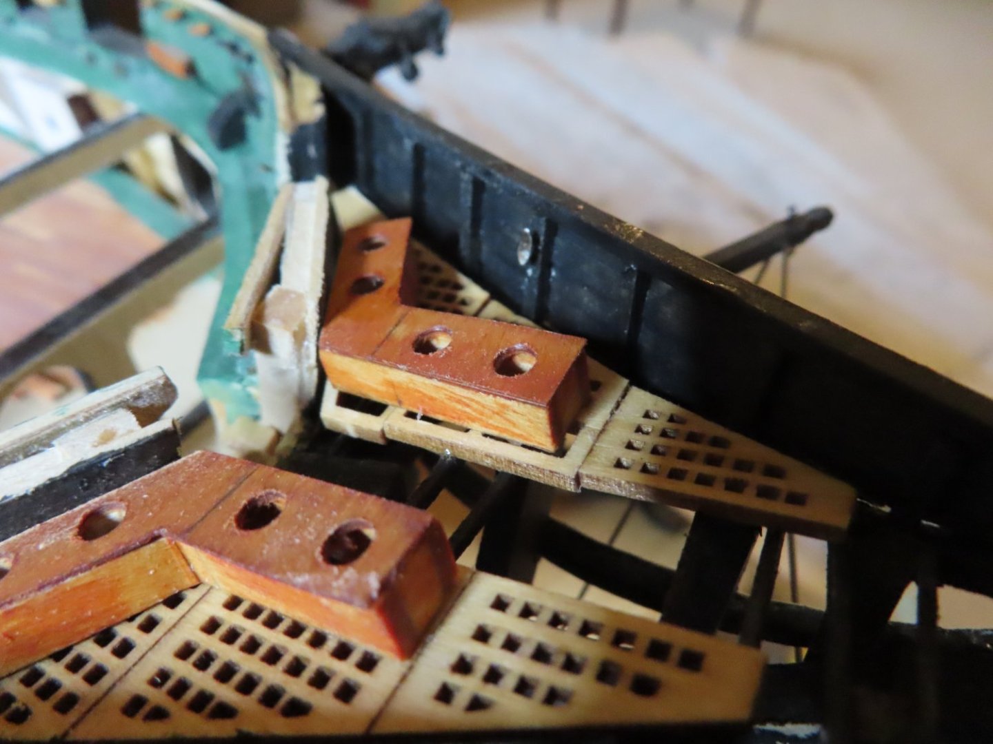
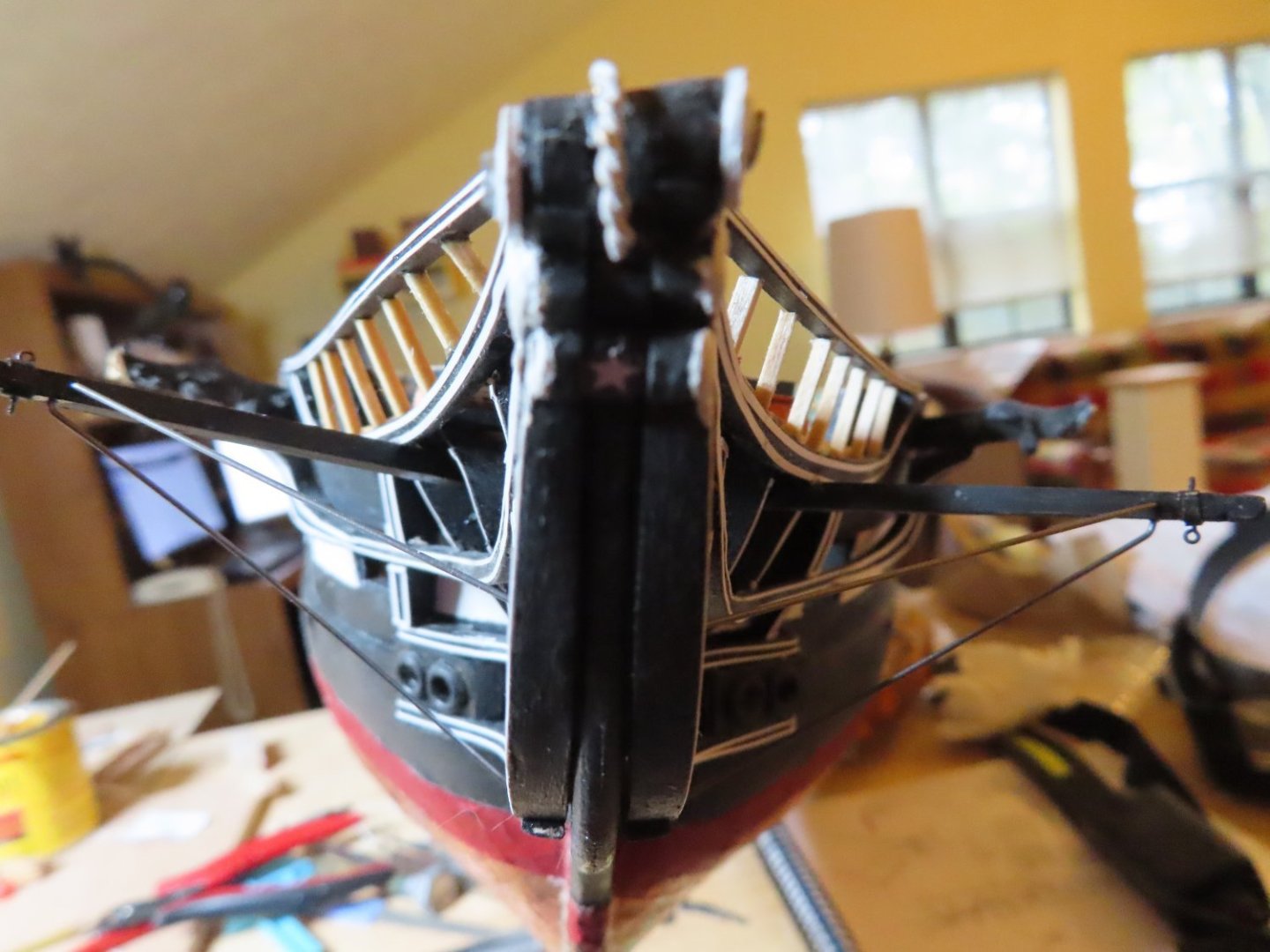
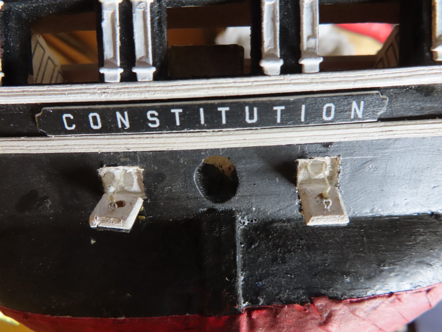
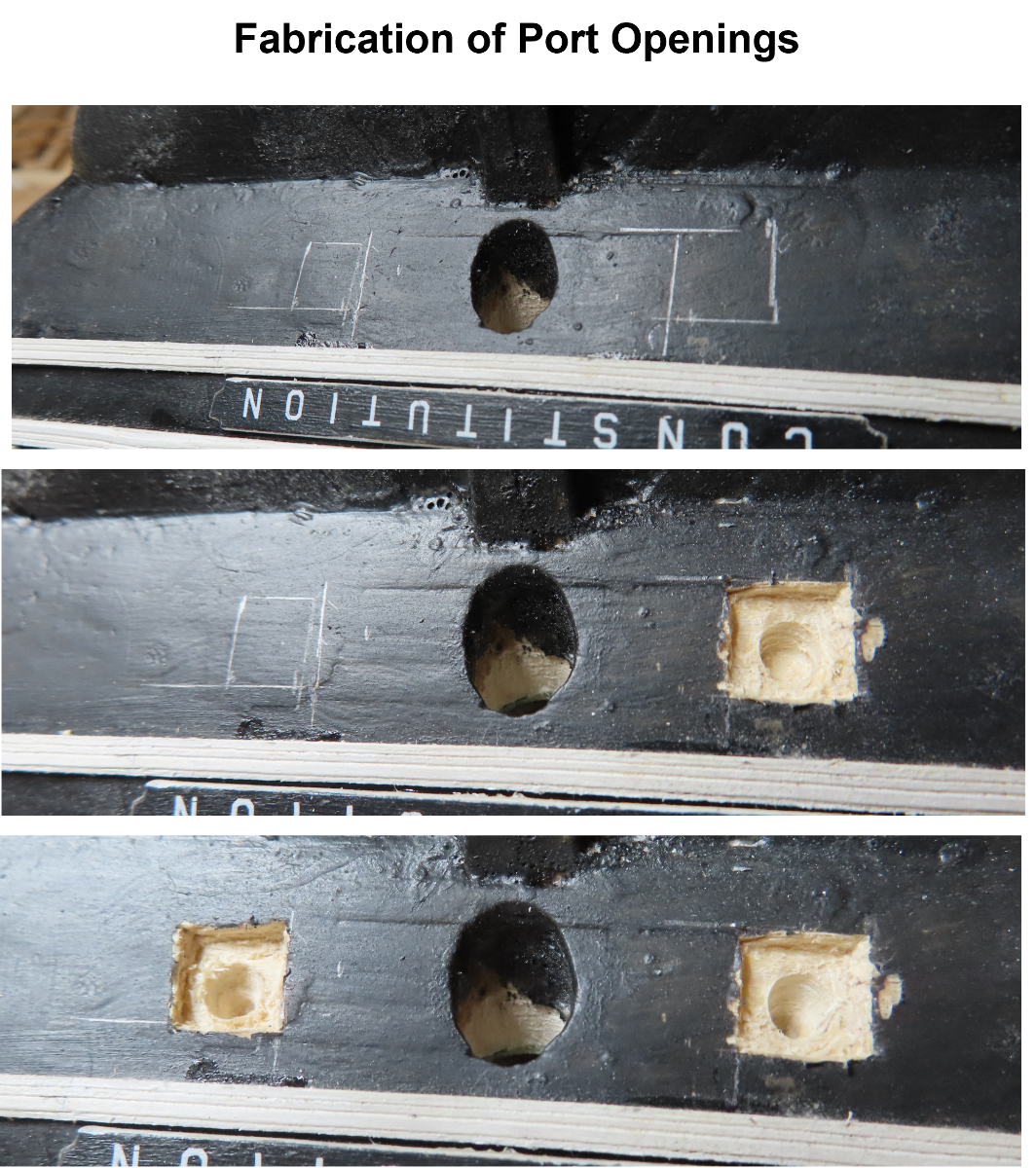
The port openings were marked on the transom and chiseled out using fine chisels and a Dremel rotary tool to a depth approximately equal to the port door thickness. Next, a hole was drilled vertically towards the tiller room area. The round opening size was determined by my calibrated eyeballs. The openings were painted white.

-
I don’t know what the purpose of these ports is. I can only speculate that maybe they are used for the maintenance of the rudder assembly or even repair of the rudder at sea. Possibly, ropes could be lowered down to facilitate an ad hoc rigging of the rudder due to battle damage. Or it could be simply a way of venting air in the tiller room. If anyone knows what these ports are called or what their purpose is, please let me know.
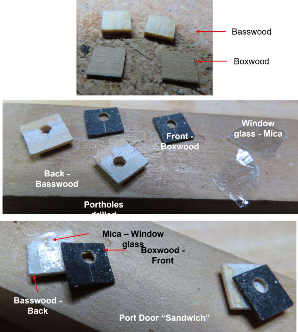
The kit plans for the port doors show they are to be fabricated and installed in the closed position on the model. The practicum goes one step further and just etches the port door seams into the hull with an X-acto knife. No fabrication at all except for the round porthole because as the practicum states: “These ports are barely visible close up so no need to go overboard with them.” Well, as most of you readers know by now, I like detail. So, not only will I fabricate them, but I will also attempt to install them in the open position. I just can’t help myself.
My port doors were constructed like a sandwich. The outer layer was 1/32” boxwood to be painted black on the outside face, The middle layer is a piece of mica to be the porthole glass, and 1/16” basswood for the inside layer with its face to be painted white.
-
Rudder Post Ports
For the time being, I’ve finished with the bow excluding the bowsprit and rigging. It’s time to work once again on the stern. First up, the two ports on either side of the top of the rudder post. The practicum calls them “chase ports” but chase ports are gun ports facing forward at the bow or aft at the stern. These are not gun ports on the USS Constitution. When the port is opened, you can see there is a round cross-section tunnel leading up to the tiller room area in the berth deck above. There is no room for a gun or even a man standing. Surprisingly, I could not identify where the tunnel opened in the tiller room.
.thumb.jpg.c9d7b1cf07b26c19ada5a96cb96a3c6c.jpg)
-
-
Your jib sails are very neat and clean. Well done.
You have constructed your model a whole lot faster me. I started in 2017 and five years later, I have still not completed the hull. Of course, my Model Shipway kit is a larger scale at 1:76.8 (more detail) and I decided to add the gun deck to my model. So, I have not reached the point where I have to make the decision whether or not to rig the model with sails. The only boat I've ever added sails to was the Evergreen (my 1st wooden model) which you can see in the little image I use as my identifier to the left of my comments, so I don't have a lot experience making them That being said, the reason I haven't made that decision is scale. When you scale down the thickness of the sail material which isn't thick to begin with, it's almost gossamer thin and semi transparent and I've had difficulty finding modeling material to emulate that. Just about every model with sails has dealt with that by ignoring the scale and gone for the appearance. You are doing a fine job in that department. I look forward to your next post.
-
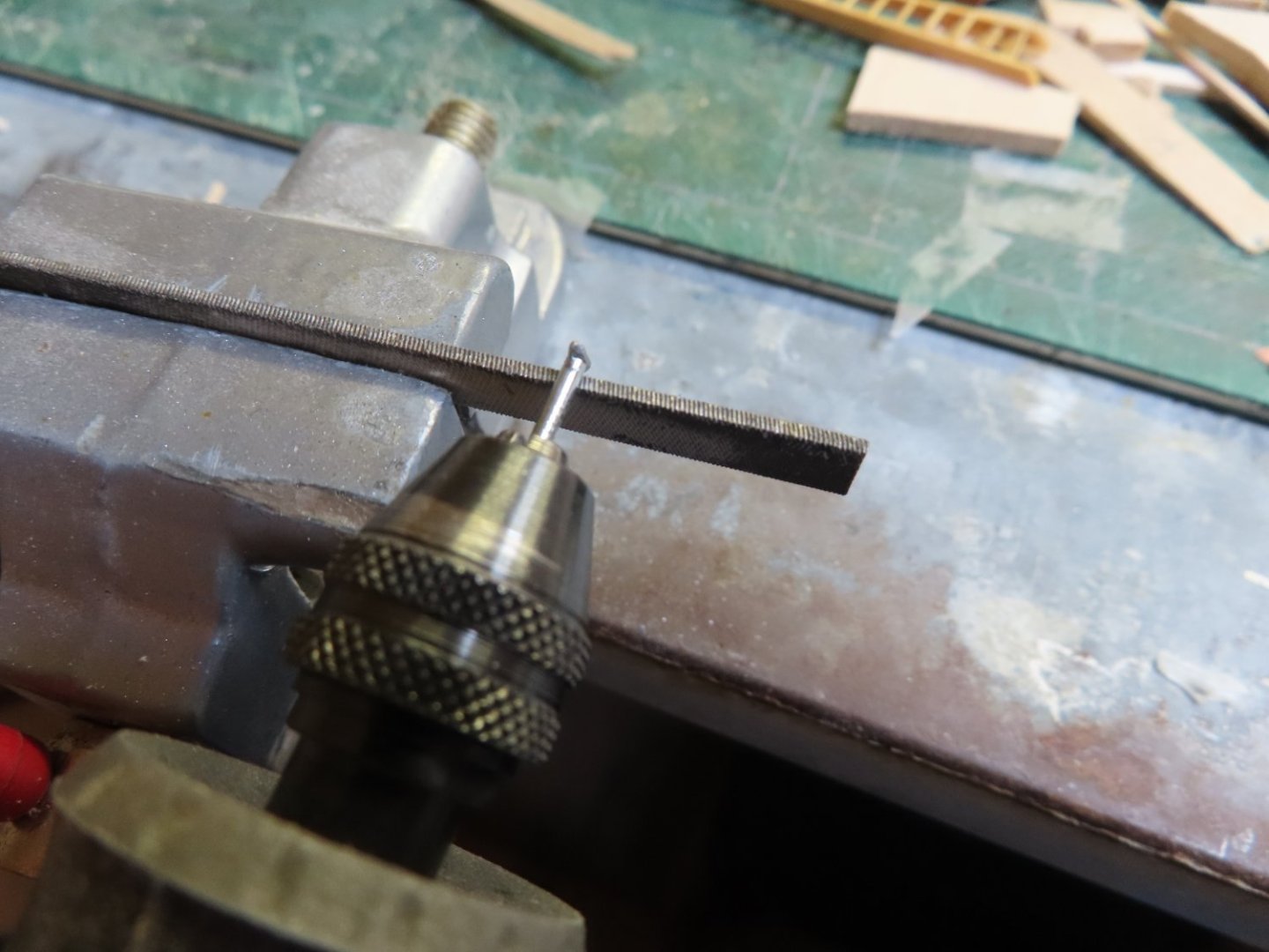
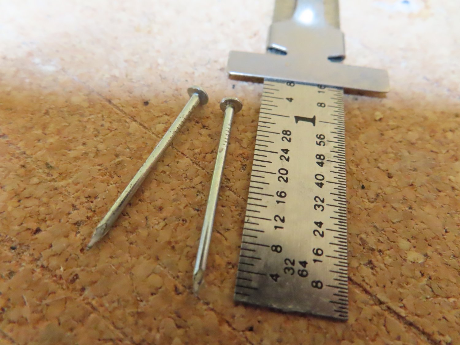
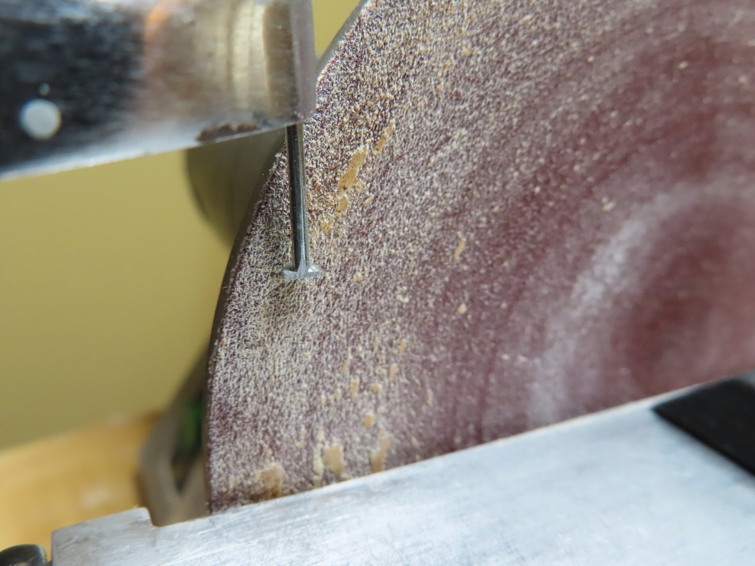
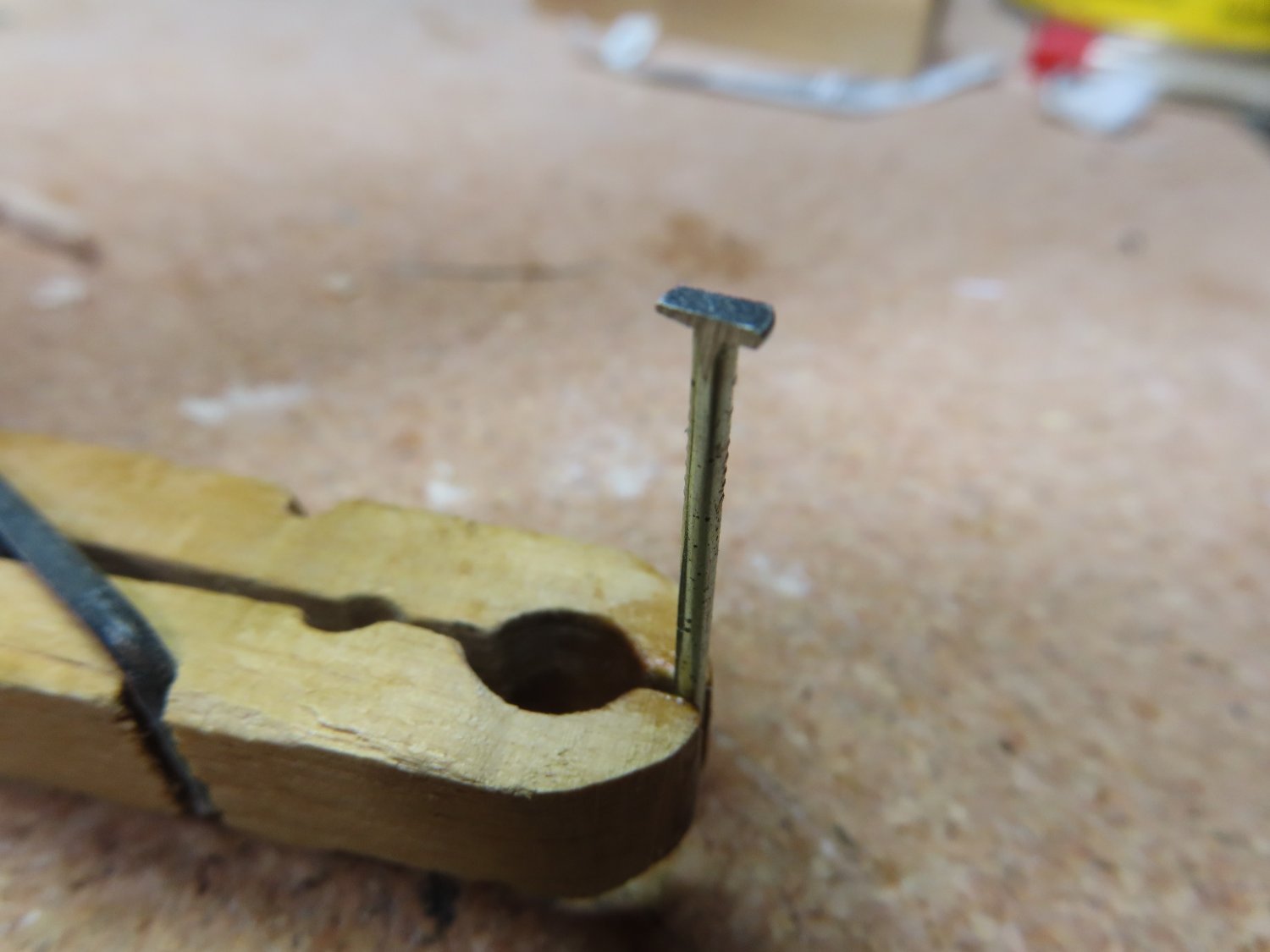
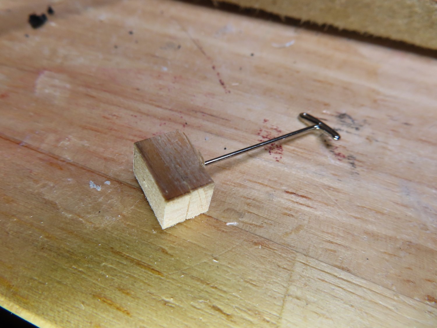
Using a 1” nail with a flat head, I ground off two opposing side flush to the shaft. Then with a Dremel rotary tool and needle files, the remaining portion of the nail head was fashioned to look like a cleat. Next, the shaft of the nail was placed into the Dremel rotatory tool so it acted like a mini lathe. A file was clamped with a vise and the nail shaft was ground such that the shaft was narrowed down to a very small diameter while leaving a small section at the top, thick. When satisfied, the part was cut off resulting in two tiny cleats with a pin at their base which was inserted into drilled holes (#44 bit) on the fourth posts port and starboard.


-
One last check of my photos revealed one more detail, a cleat had to be installed. I was going to check my supply of cleats I previously purchased building the Rattlesnake but for the life of me, I couldn’t find them. They were not where I thought I stored them. This gave me a chance to brush up on making them with a method I taught myself some years back.

-
1/32” x 3/32” basswood was used as the planking material in lieu of the plan called 1/64” x 3/32” stock because that was not supplied in the kit as noted in the practicum. I believe that the 1/16” was a typo in the plans. Each plank had to be custom sized and shaped before installation. I painted the top and bottom planks black before installing them to make painting near the rails easier later on. Bothe sides of the planking were painted black.

- robdurant and Ryland Craze
-
2
-
Using a 3/8” spacer, seven 1/16” x 1/16” vertical posts were spaced and glued into place from the second rail up to the first. The plans appear to show an eighth post right next to the hull, but since that rail would be buried behind the forthcoming planking, it wasn’t worth the effort to install it.

- robdurant and Ryland Craze
-
2
-
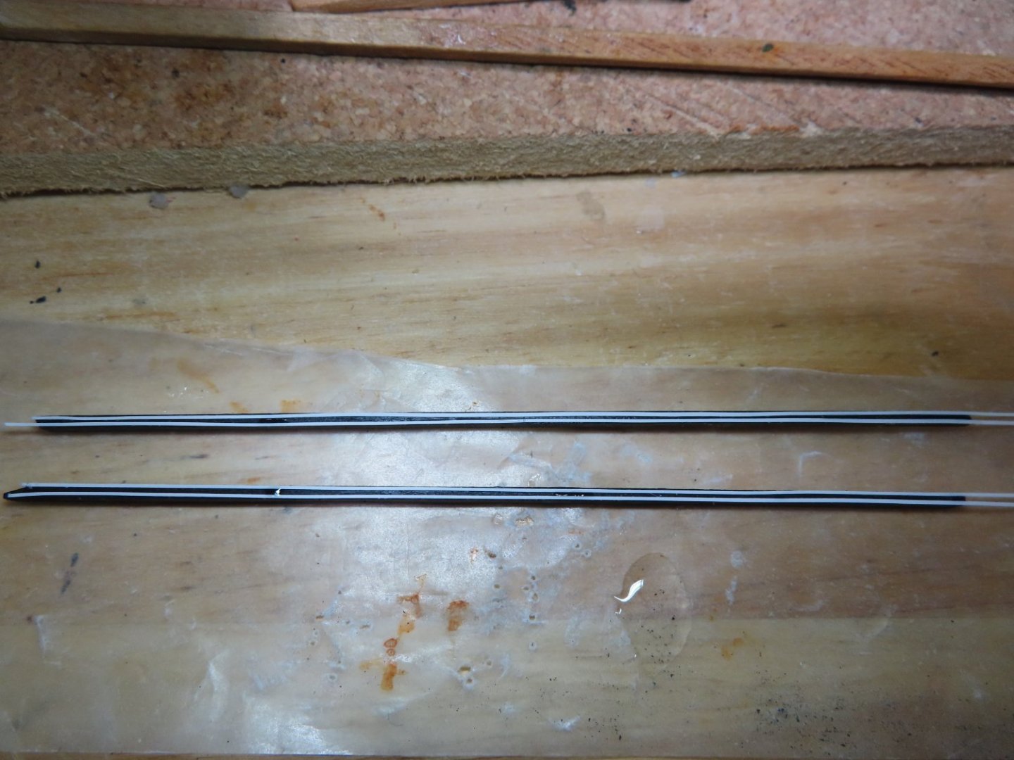
The final major part of the bow is the bow top rail and the planking below it. Finally, a simple rail to construct. It is a straight piece of 1/16” x 3/32” stock basswood, cut to length, painted black with 1/64” white pinstripes added.


- Ryland Craze and robdurant
-
2
-
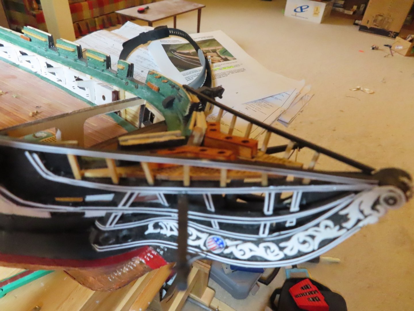
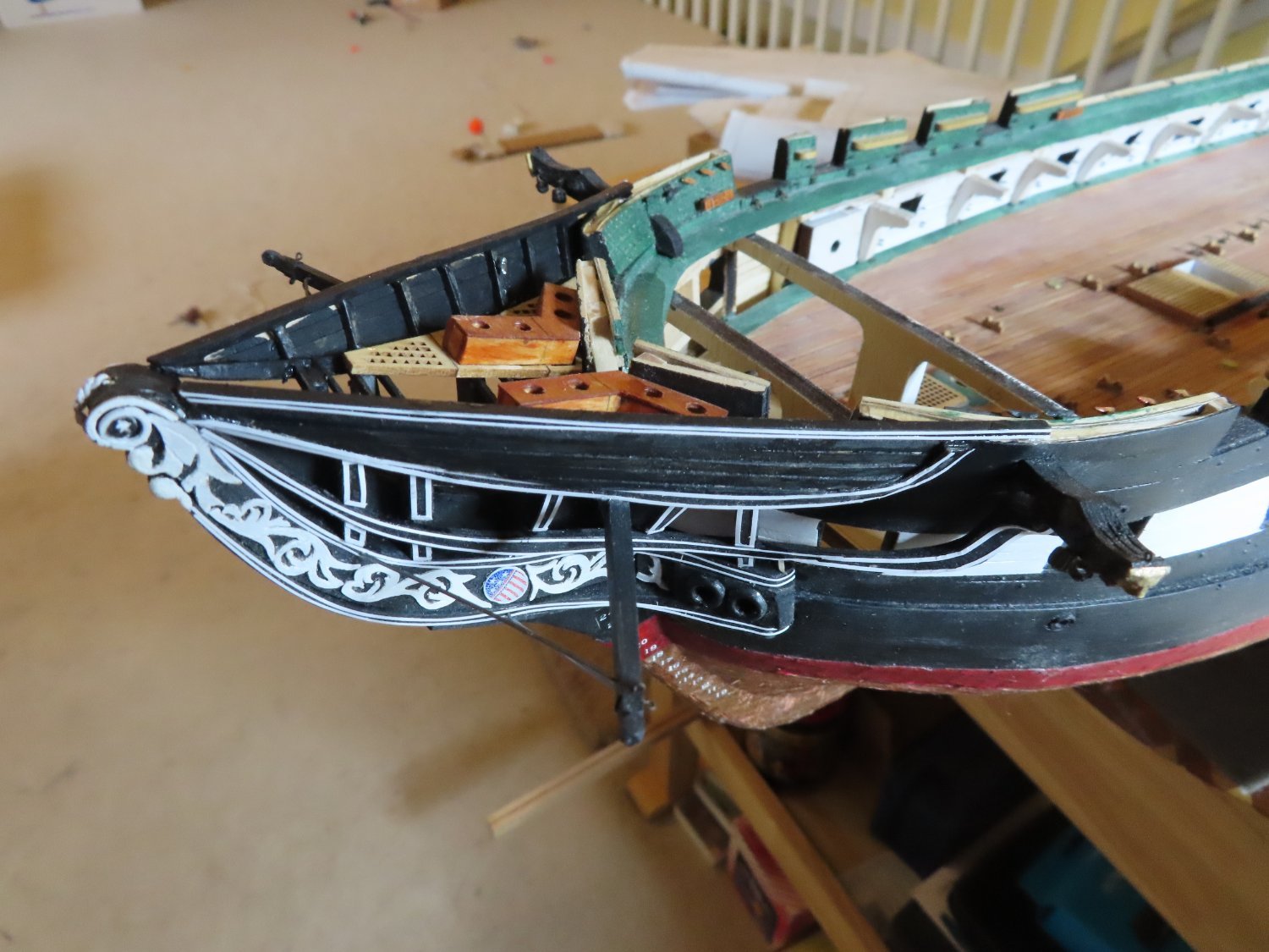
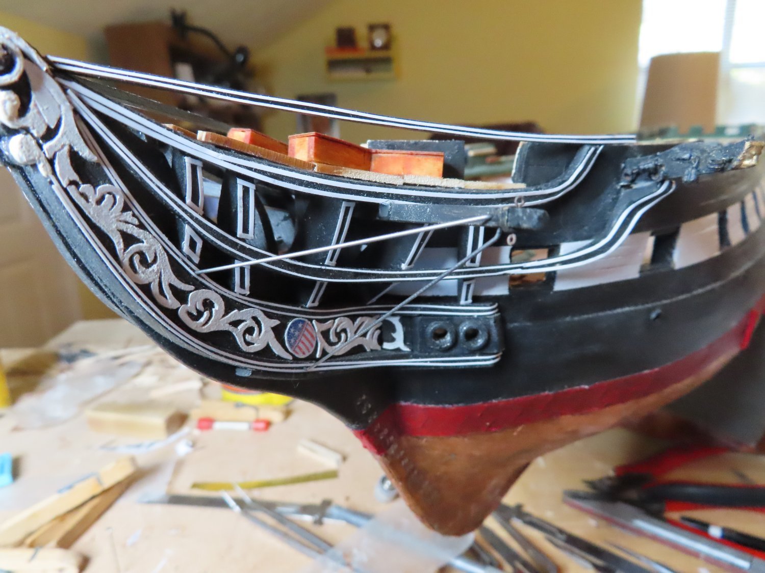
There is a slight swoop up towards the stem tip that required some fine tweaking, but I eventually got the seat of eases installed on top of the rail support bracing beams. This image shows the seats installed with the unfinished bowsprit dowel dry fitted in place for show. The top rail will complete the bow.


.jpg.d7f18aac7dace2653012eb88ca6f1176.jpg)


USS Constitution by histprof1066 - FINISHED - Billing Boats - 1:100
in - Kit build logs for subjects built from 1751 - 1800
Posted
You've got fantastic sewing skills! I couldn't put three stitches in a straight line, never mind making them all equal lengths. Great job!
Jon