


JSGerson
-
Posts
2,156 -
Joined
-
Last visited
Content Type
Profiles
Forums
Gallery
Events
Posts posted by JSGerson
-
-
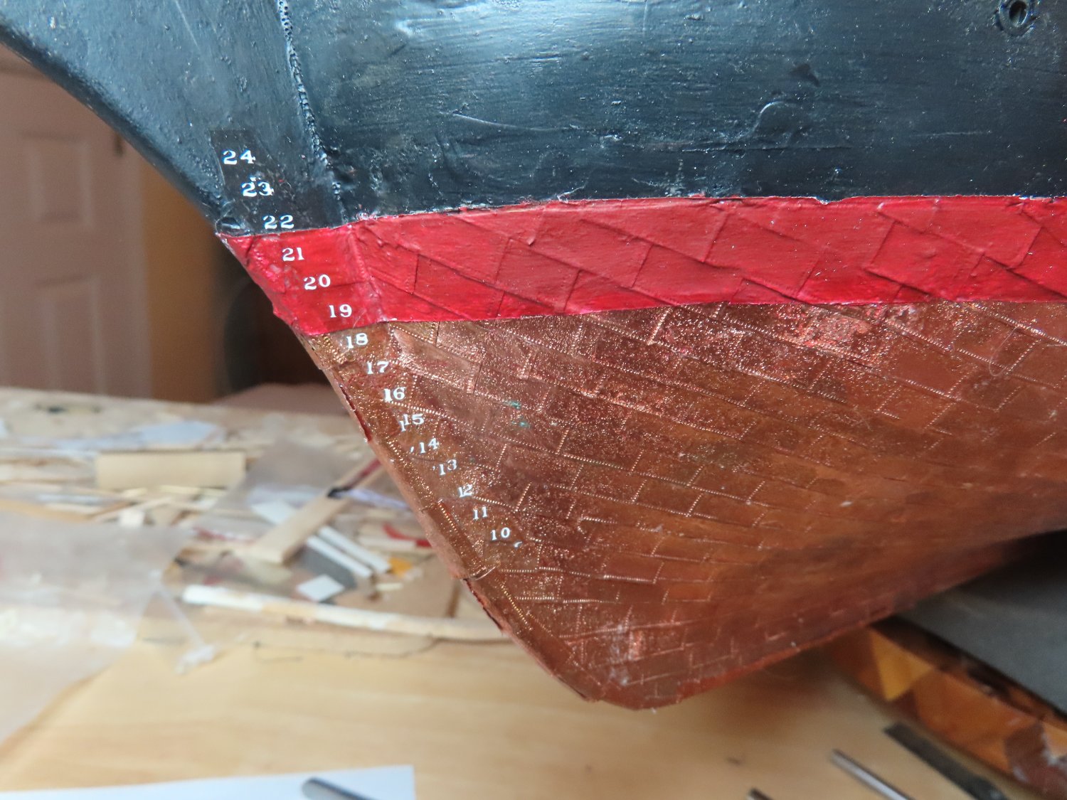
As I feared, applying the transfers to the decal paper was a bitch. I had to use my headband magnifier just to see the digits, the guide marks almost disappeared when trying to find them looking through the transfer sheet, and of course I’m applying white numbers on white decal paper. To add a little more apprehensiveness, I could not afford too many mistakes because I had a limited number of transfers and mistakes were made.
Once the port and starboard decals were made, the bonding spray was applied and set aside to dry thoroughly. These were then dipped in water and applied to the hull. The process worked, but my alignments were not as perfect as I would have liked due to the difficulties I mentioned above. Micro-Coat Flat was then applied to remove the sheen and blend the decal into the background. From about a foot away, the numbers are almost too small to be read, so the imperfections are not too noticeable.

-
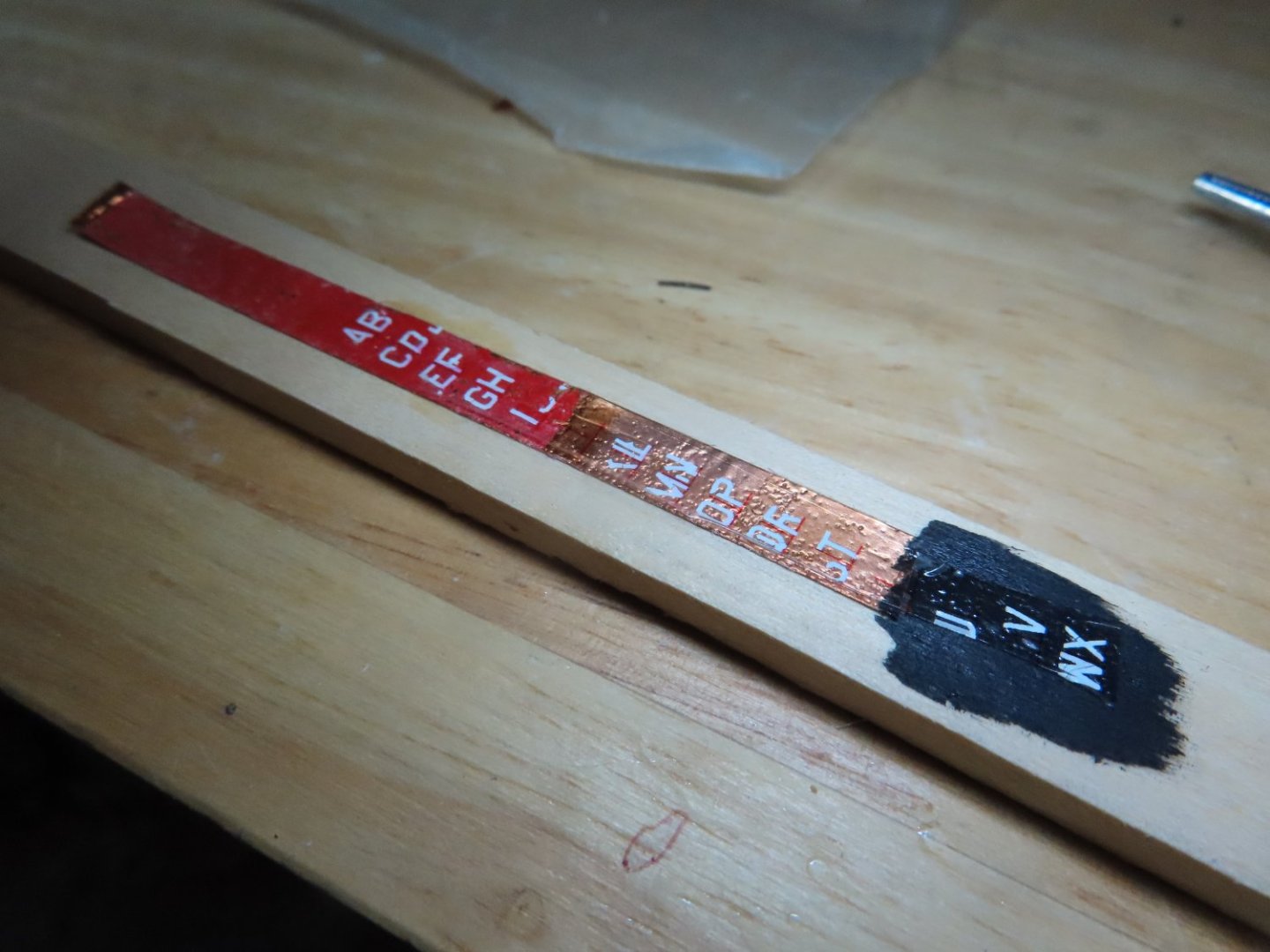
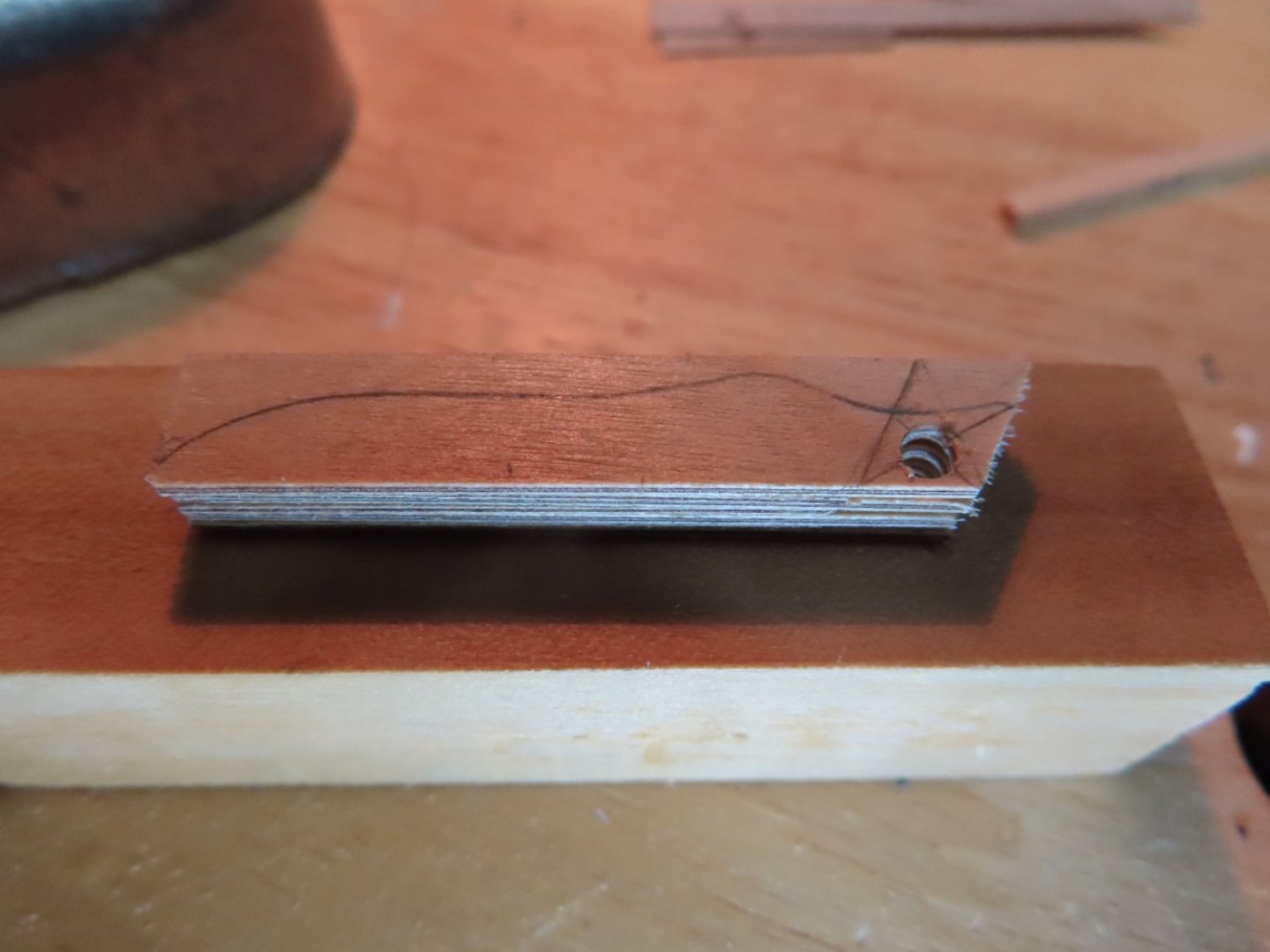
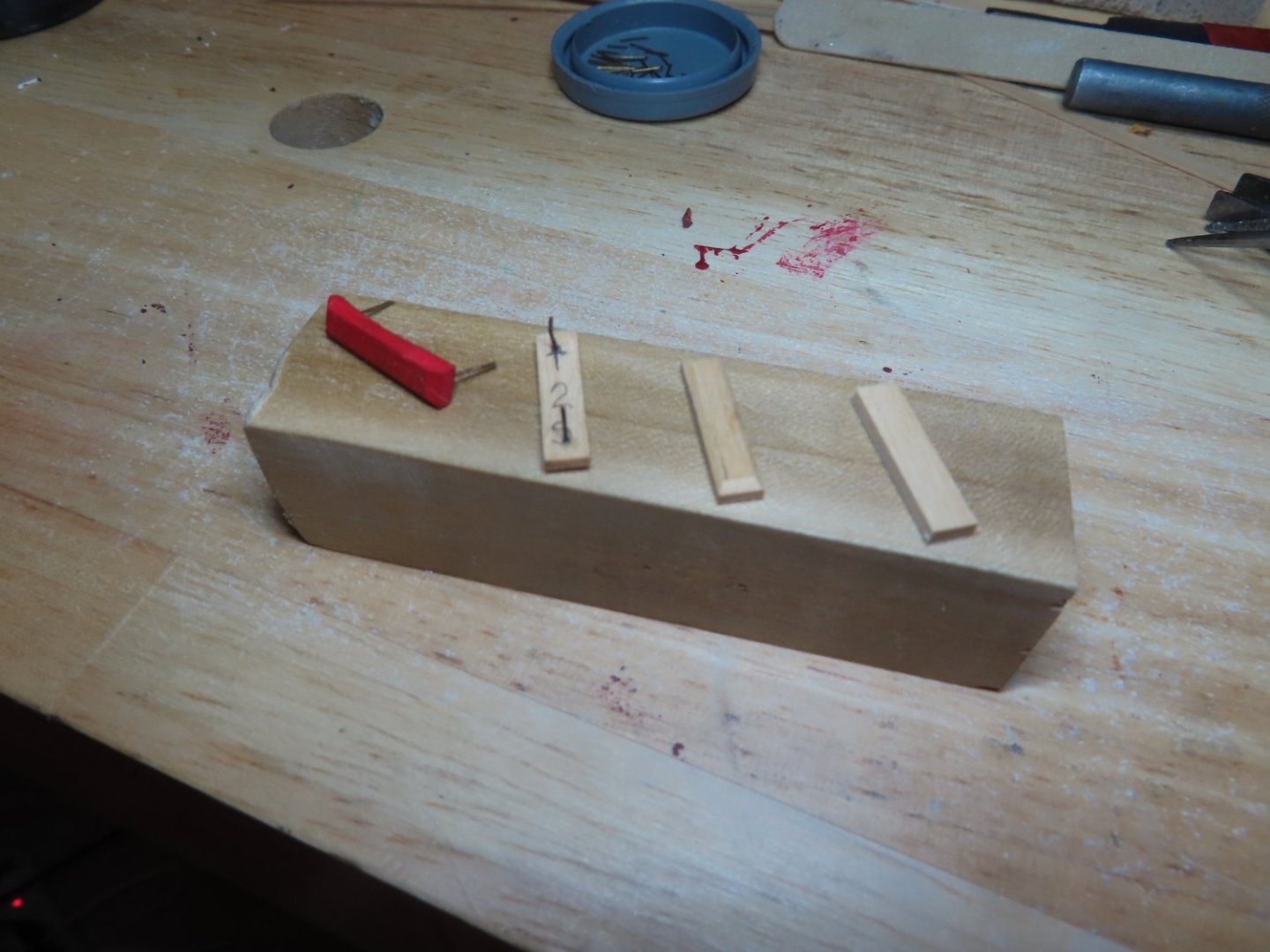
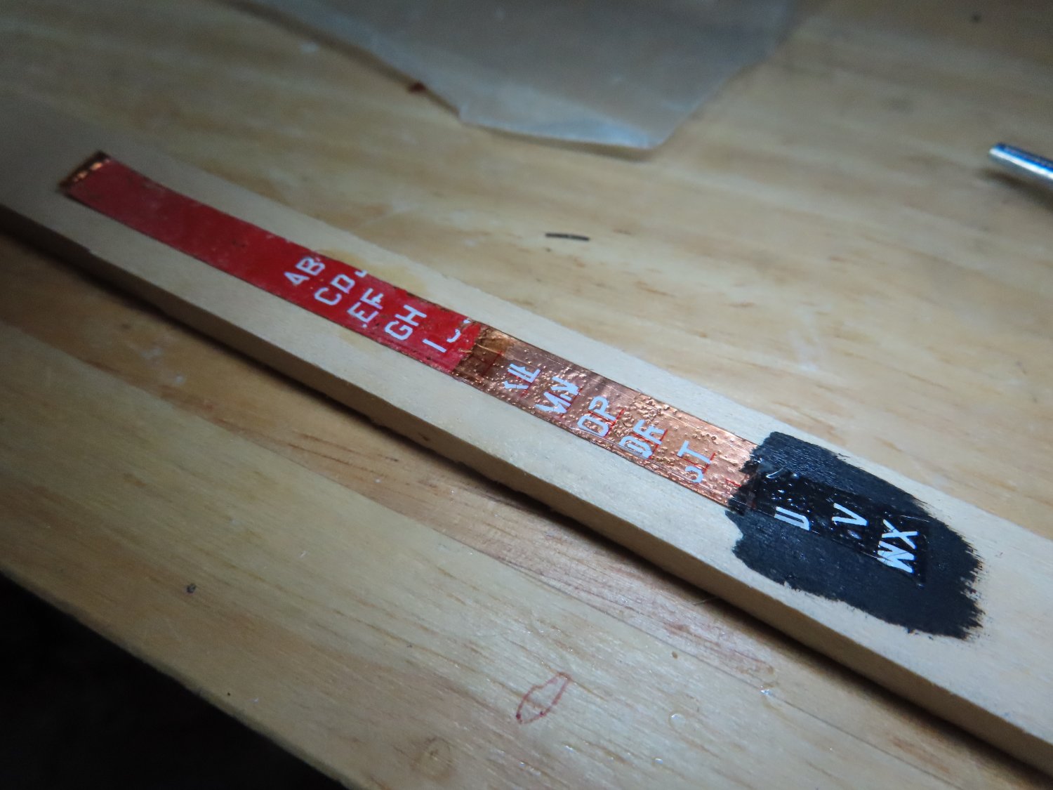
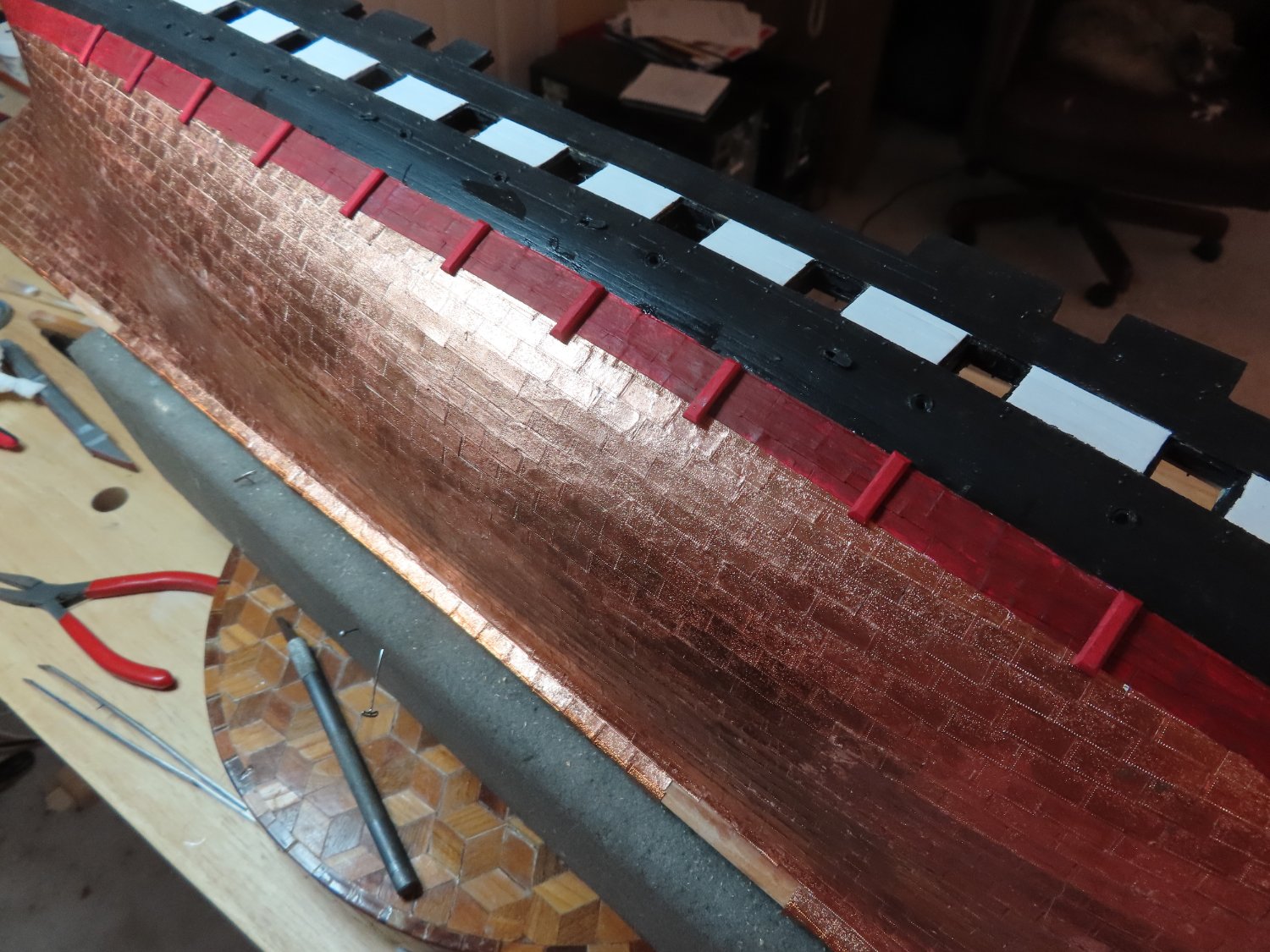
Because I have not seen this process done by anyone before, I did an experiment first. Using lettering left over from the ship’s nameplate, letters instead of numbers, I follow the above plan. I used a strip of copper, partially painted red and black painted wood as my test subject. What I discovered is that it worked, however you had to be very careful and meticulous burnishing the transfers. Because it’s white lettering on white decal paper, it is very difficult to ensure a proper transfer as seen in the image below. I believe there is colored decal paper (light blue I think) which would have made this process a bit easier, but I didn’t have any. The guide marks were essential. Although my marks were fine red and they did seem to disappear once the decal was applied to the surface, I changed them to grey guide mark for safety.
-
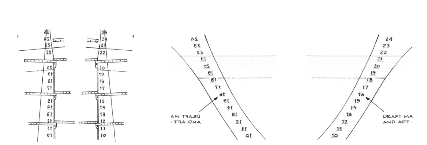
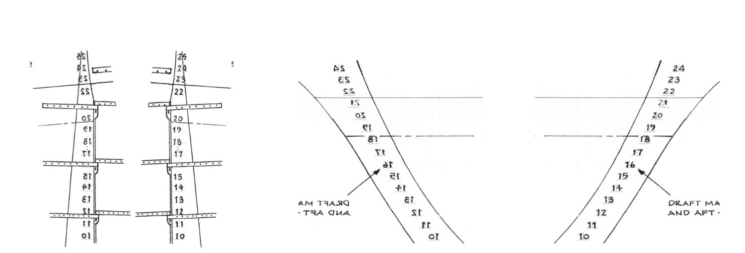
The MS Plan showing the bow and stern draught numbers were scanned to capture them. These were then imported into PowerPoint (my only drawing program) and properly sized the clipped images so they would print at the correct size., These were then copied and flipped vertically so I ended up with port and starboard of the bow and stern numbers.
Note: I used the alignment function of PowerPoint to distribute the marks evenly vertically. As it turned out they did not match up exactly with the vertical number spacing on the drawings. Although my spacing will be correct, you can’t see any real difference.
Once satisfied, line guide marks (wide upside down “T”) were overlaid onto the numbers to indicate vertical spacing and the curve. You might just make them out in the image below. It’s only the guide marks I need to print. They were to be used to guide me in the application of the dry transfers. Using the guide marks, the dry transfers were to be applied to the decal paper then sprayed the decal bonder. I had no idea what the bonder would do the dry transfers or whether the dry transfers would lift off the decal paper once the decal was dipped into water.
-
I had a good idea why this was so, and even contacted Robert Hunt to find out why he didn’t add them. He confirmed what I assumed; they are too small to paint on the models at 3/32”. Why not make decals? Also, a simple answer, no home computer can print white because they don’t use white ink. My next thought was to use white vinyl lettering, but I couldn’t find any made at that small size. My last choice was dry transfer lettering. They do make small enough sizes although not in the exact font used in the present-day configuration: Engravers MT. However, it would be very difficult to align them properly directly on the hull with no flat smooth surfaces.
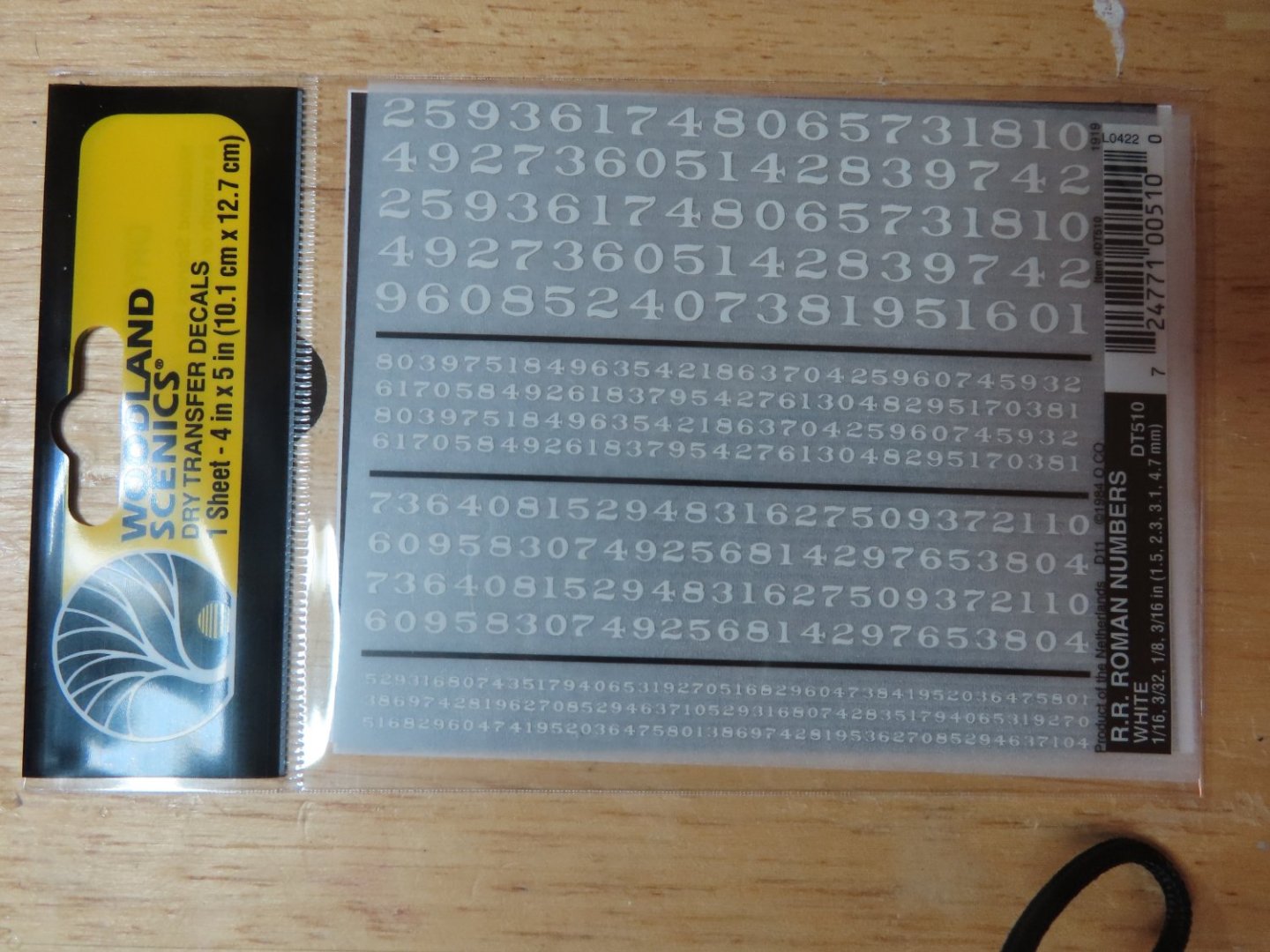
But I had an idea, why not combine decals with dry transfers? When I bought the dry transfers for the ship’s nameplate a while back, I also purchased Woodland Scenics R.R. Roman Numbers White # DT510 which came with 1/16”, 3/32”, 1/8”, and 3/16” sized fonts. At this scale the difference in fonts from the actual one would not be noticed. I had to buy three sheets in order to have enough of the proper digits. As you can see from the image below, the font size I was using is on the very bottom of the sheet.
-
Draught Marks
Maybe it’s procrastination or trepidation of the head rails, but I decided to hold off on the head rails one more time because I thought it would be a bit easier to add the draught numbers on the bow at this time, I’ll hold off on the stern until I’ve added the hardware to support the rudder.
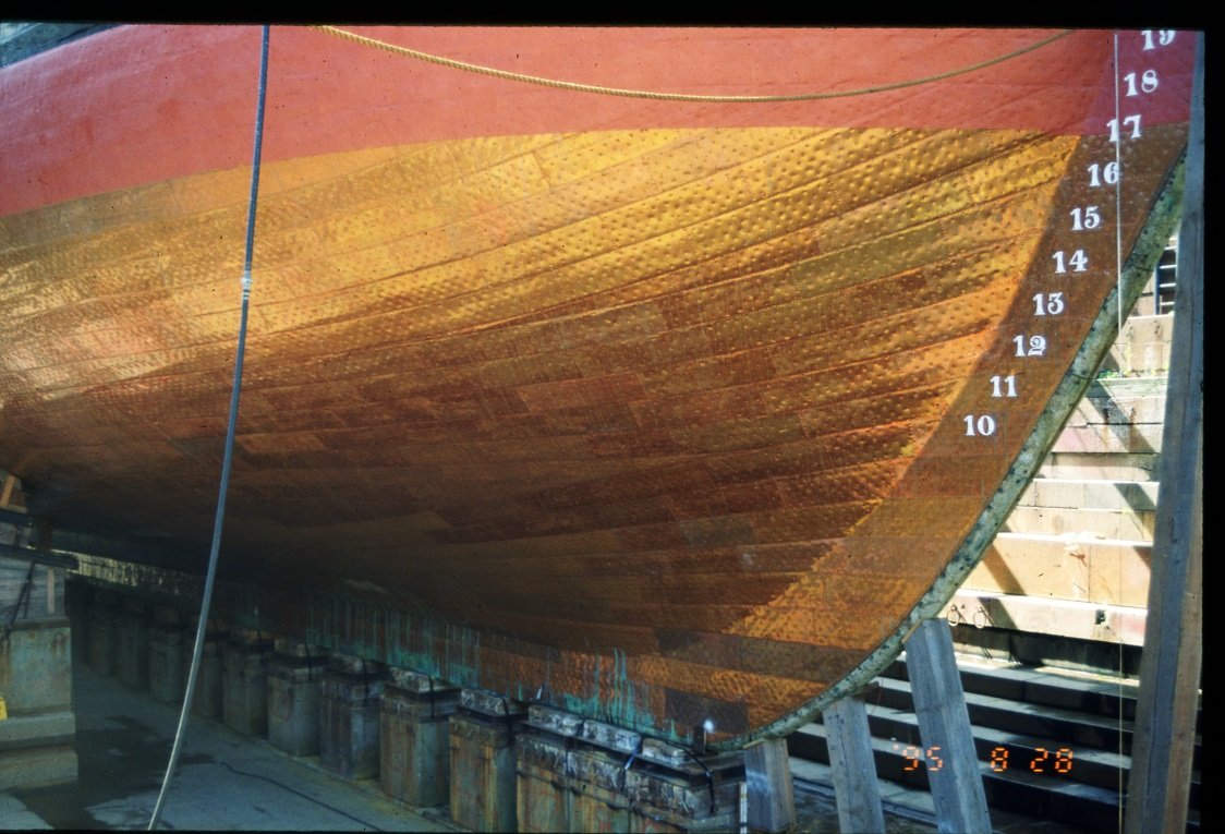
As I looked over most of the models of the Constitution built by others, the one thing they have in common, they did NOT add the white draught numbers which are really quite prominent for the last 100 years or so.
-
You might consider using brass tubing to make tiny thimbles. Obviously, the hole is already there. All you have to do is slice them off the tubing and paint. If you need to carve a groove on the outside perimeter of the thimble, place the ring on a tapered mandrel which will hold the ring tight while you file the groove. Wood becomes very weak at that scale as you have found out, whereas the metal thimbles remain strong and won't break. At this scale it will be impossible for the viewer to know what material they are are made of. It's a model, not a reproduction,
Jon
-
-
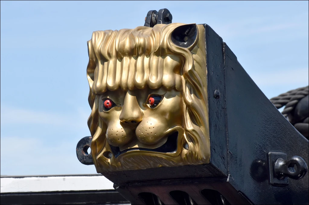
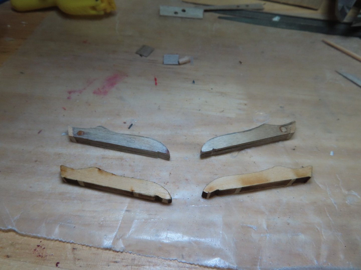
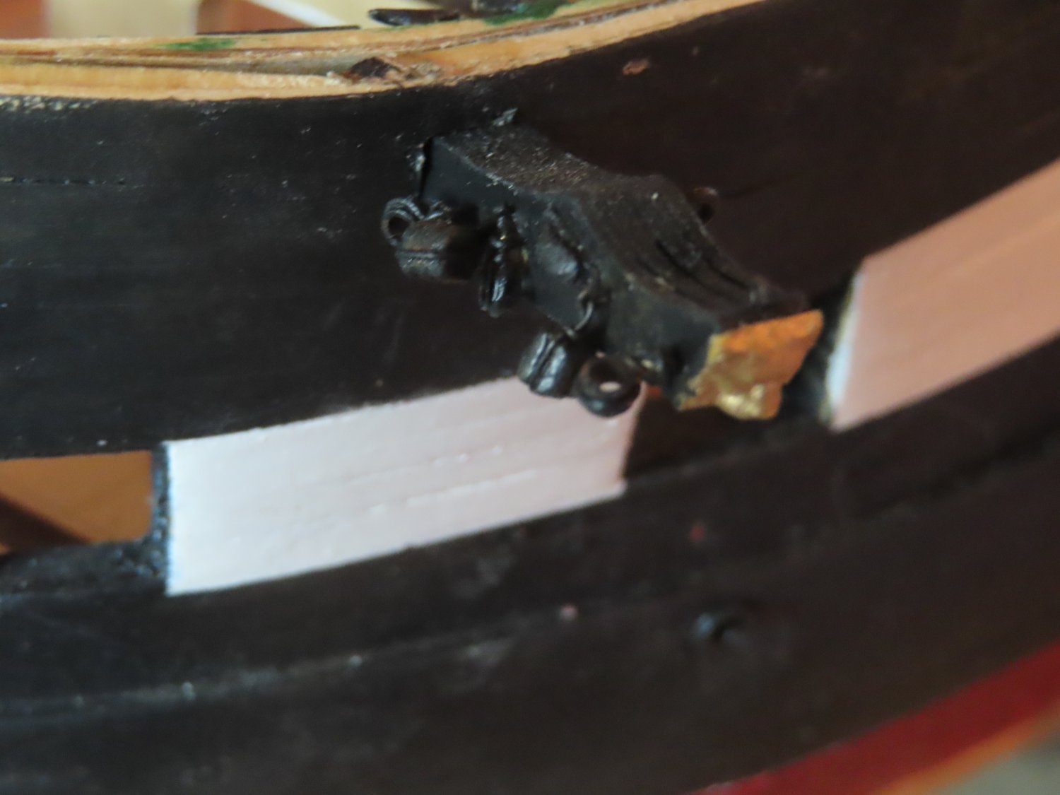
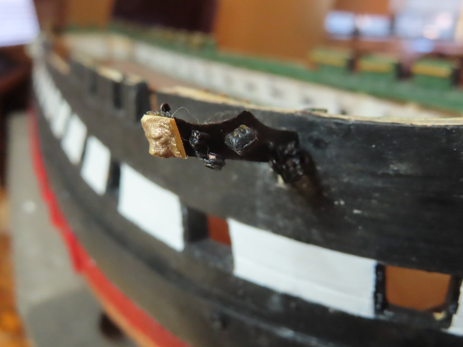
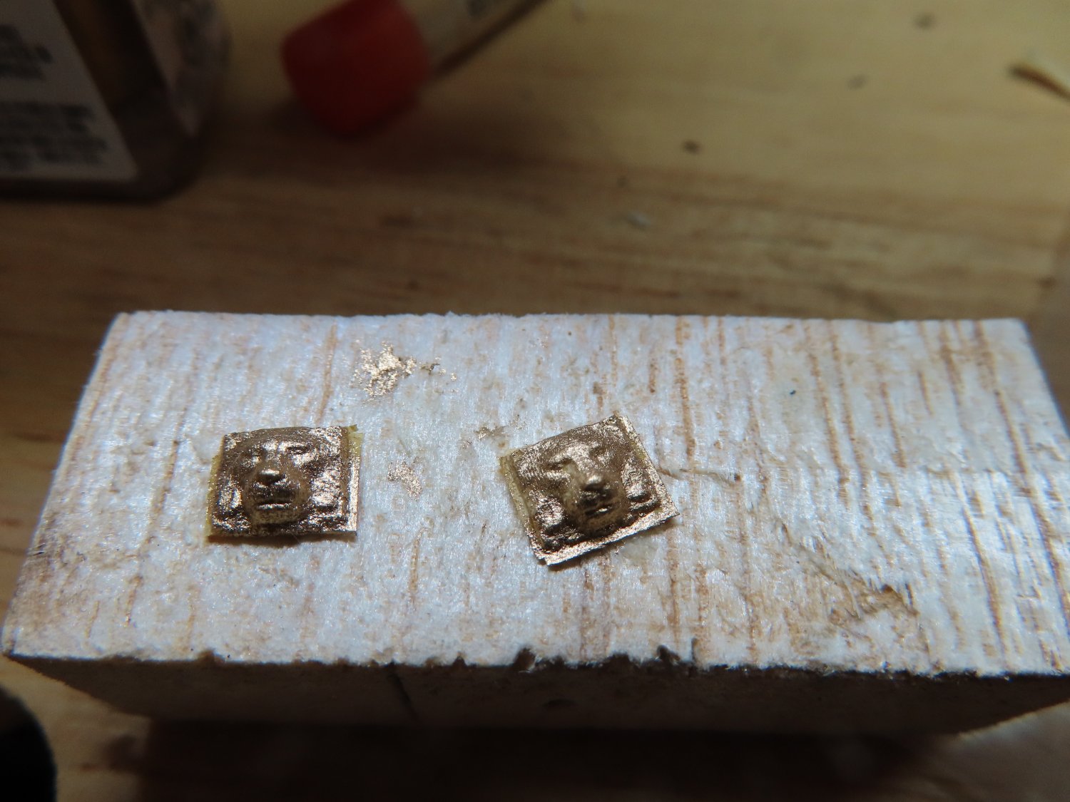
The parts (except the carvings) were assembled, and everything was painted black as per the actual ship photos. The carvings were painted gold with enamel paint for a shiny appearance.

-
Cathead Assembly
The only parts left were the cathead sculptures. I know my limitations, and sculpture is not one of my talents. Taking a shot in the dark, I Googled “model Cathead carving” and found just what needed at AliExpress.com. It’s not an exact match, but it’s a whole lot better that I could have fabricated. It’s close enough for this scale. It takes a while to ship it from China but to be fair, I did this last year in anticipation of this, so I had the parts in hand waiting for my use.

-
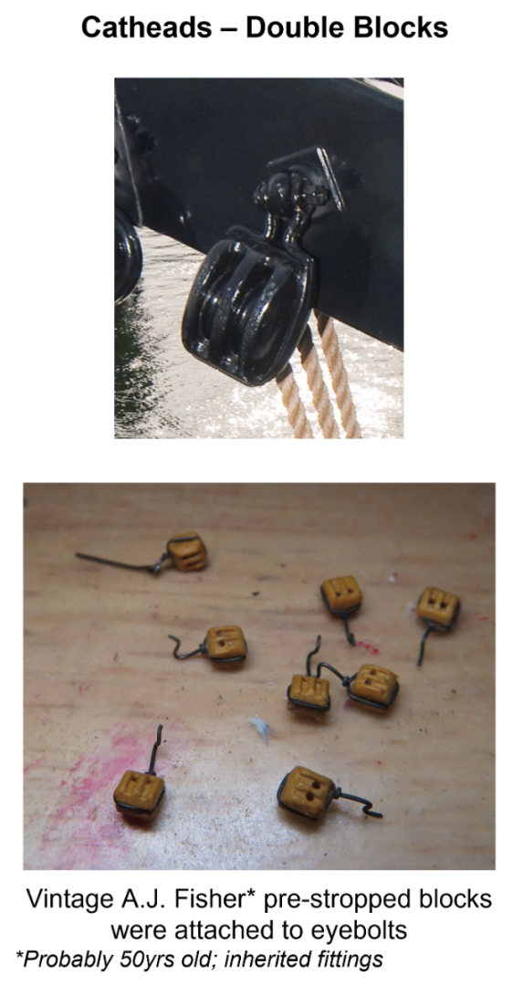
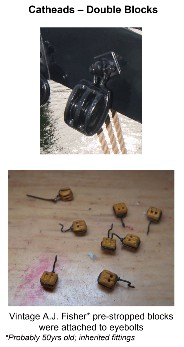
Cathead Double Blocks
I got lucky on the double blocks. A friend of mine, a model train buff, was given a bunch of old ship fittings way back when. Because he knew I made wooden model boats, he gave them to me. Among the gems were vintage A.J. Fisher pre-stropped blocks which were the perfect size for the catheads. For all I know they may be 50yrs. - 60yrs. old. All I had to do was attach them to the eyebolts.
-
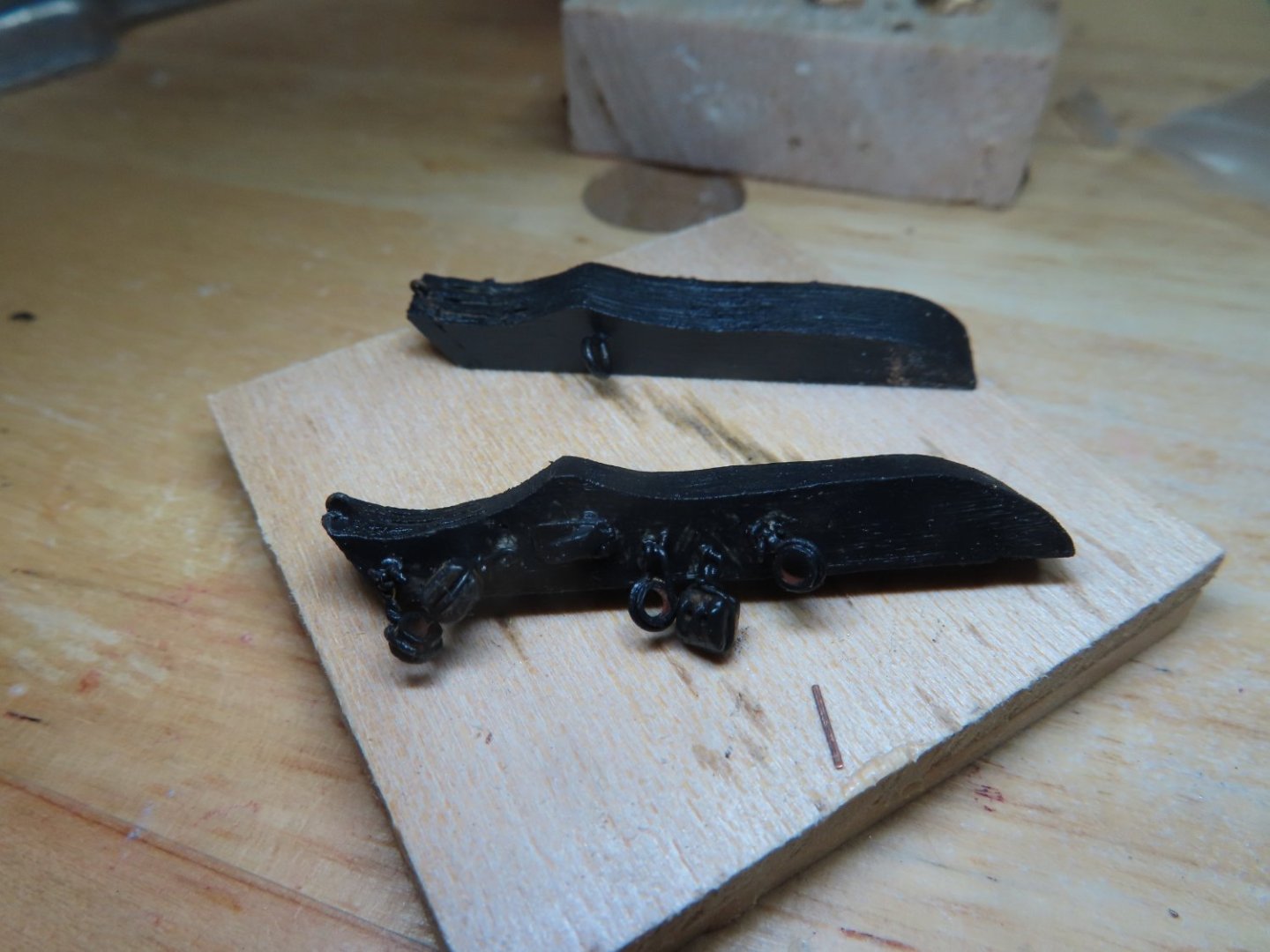
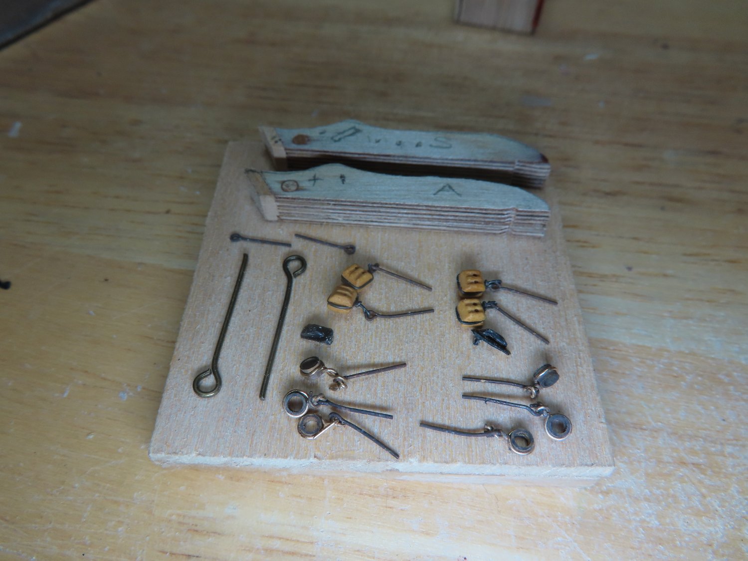
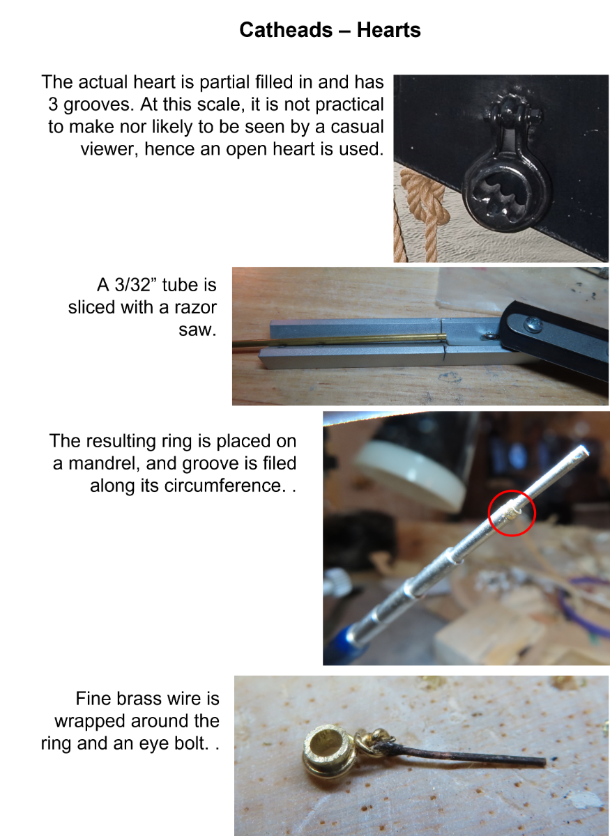
Hearts
The actual hearts are partial filled in and have 3 grooves. At this scale, it is not practical to make nor likely to be seen by a casual viewer once the parts are paint black, hence a simple open heart was fabricated. They were made by slicing 3/32” dia. brass tubes to create rings. The rings were placed on a mandrel for ease of handling and a circumferential groove was filed. Brass wire was used to strop the hearts because the actual hearts were stropped with metal. This was done by wrapping the wire around the ring and securing it to the eyebolt.

-
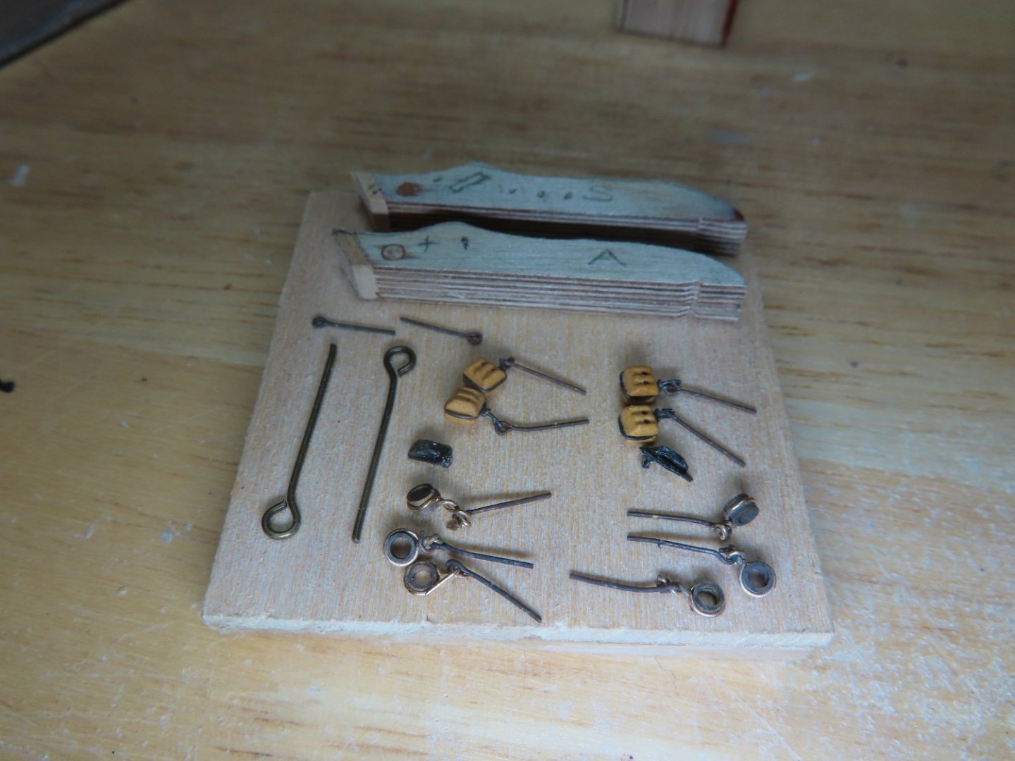
Cathead Hardware
For such a small structural piece, the cathead has a lot of hardware. All the double blocks and hearts are attached to the cathead with eyebolts and shackle connections. For the model, simple eyebolts were used due to scale.
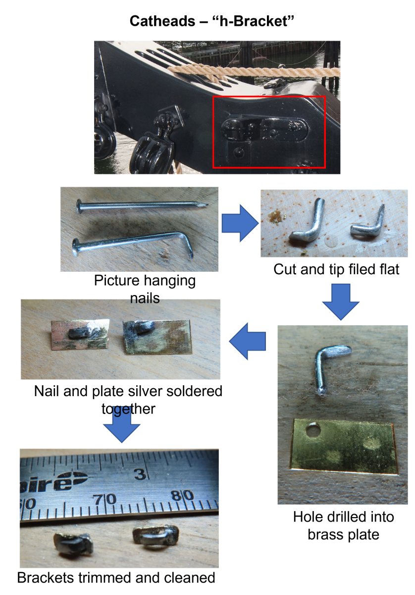
h-Bracket
I don’t know the technical term for this, but I’m calling it an “h”-bracket due to it being shaped like an “h.” I used a typical picture hanger nail and bent the pointed tip 90°, flattened, and thinned the bend portion. This was then cut off. A piece of brass plate was cut a bit larger than the final bracket size for ease of handling and a hole was drilled to accept the fabricated right-angle piece. These were silver soldered together so that the flattened nail tip was parallel to the plate leaving a fine gap between the two. The excess brass plated was trimmed to size. The actual size of the bracket was based on its relative size as compared to the cathead beam as were all the pieces of hardware. I did not have dimensions for these pieces.

-
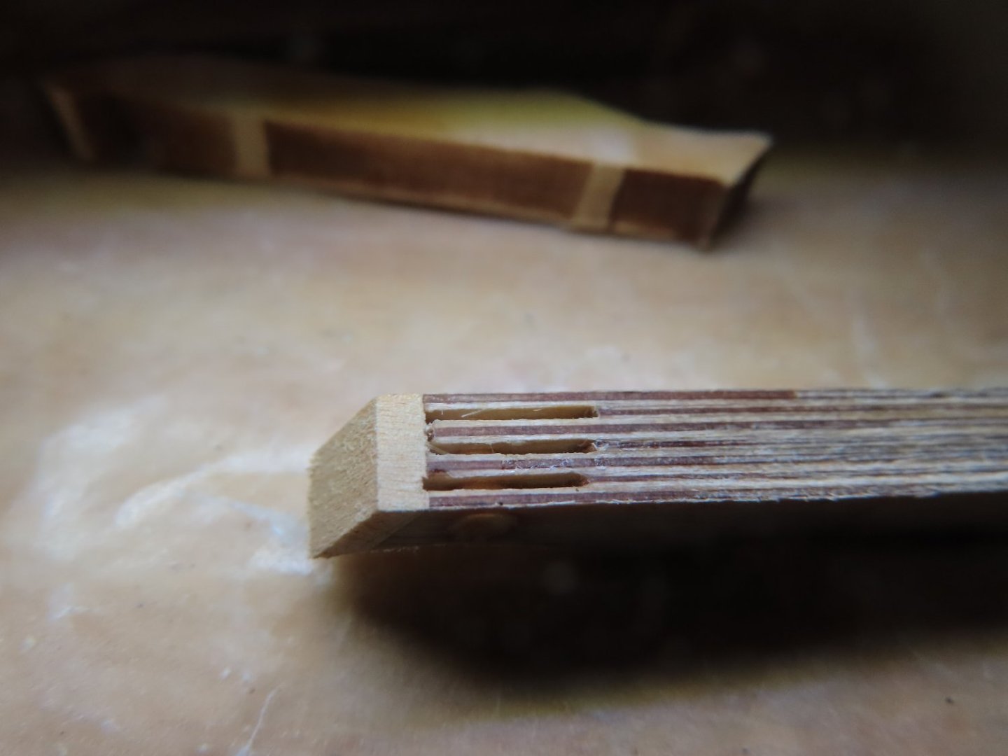
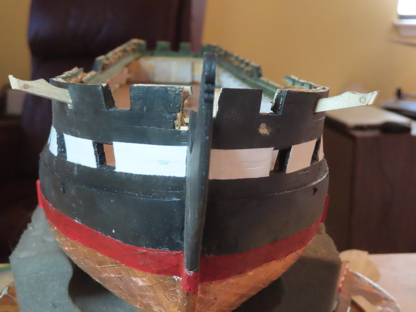
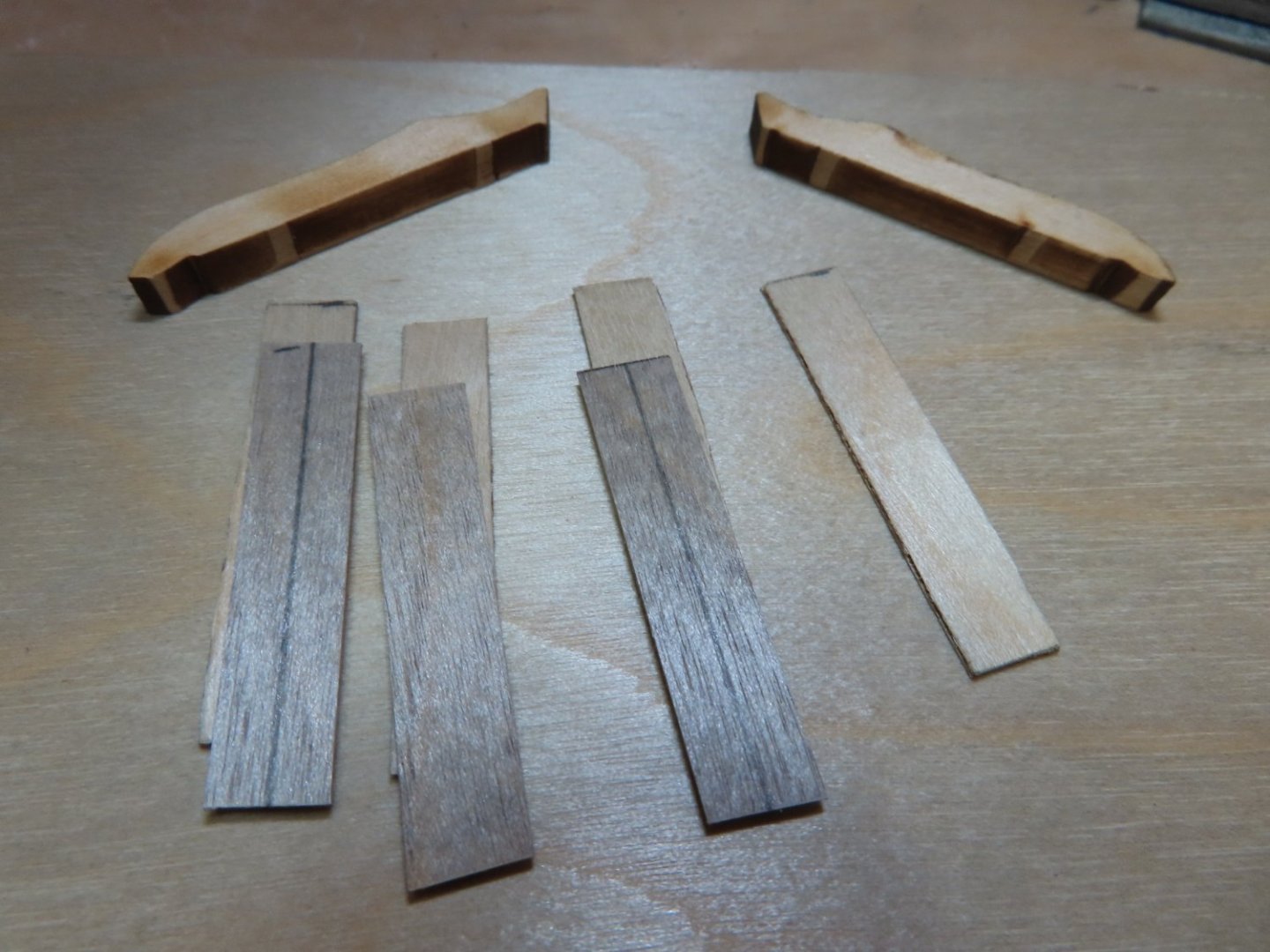
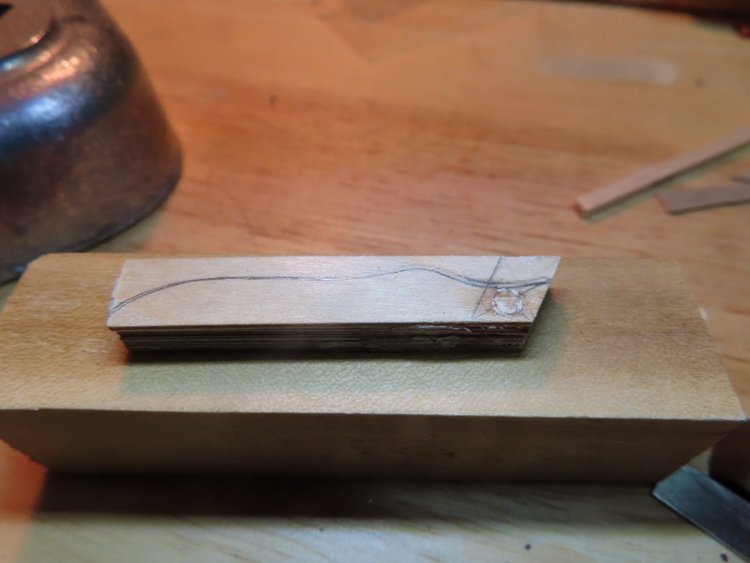
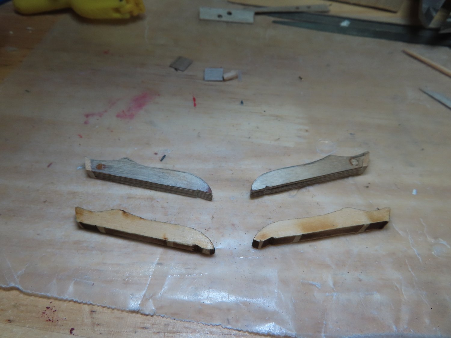
I waited 24 hours to make sure the glue dried solid. The kit supplied catheads were traced onto the assemblies and the location of the pulleys were located and drilled. I did check the kit’s cathead shape against the US Navy plans and they are a close match. The spacers were removed after the holes were drilled. Wood plugs, which would become the pseudo pulleys were then inserted into the holes, glued with CA glue and the ends cut flush. Finally, caps were glued onto the ends of the sheaves to complete the assembly. Using my drill stand mounted Dremel rotary tool with a drum sander bit, I shaped the raw pieces. The finished catheads looked almost identical to the kit supplied pieces, but these now had sheeves and pseudo pulleys.

- bthoe, KurtH, Stevenleehills and 3 others
-
 6
6
-
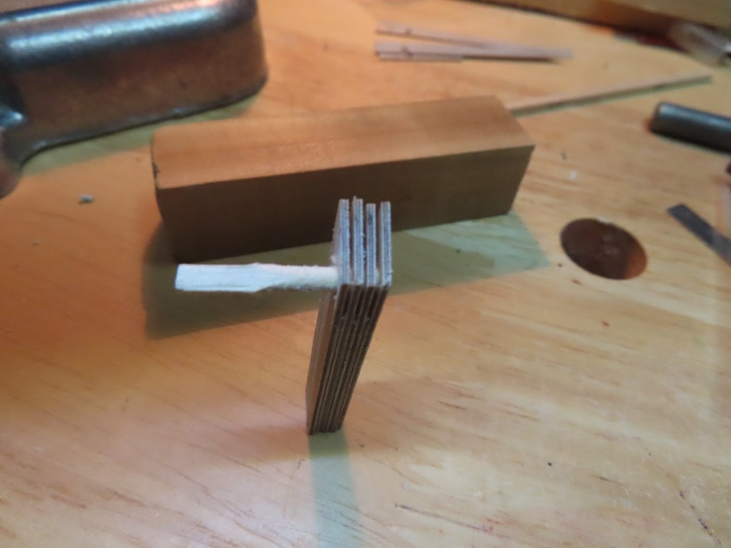
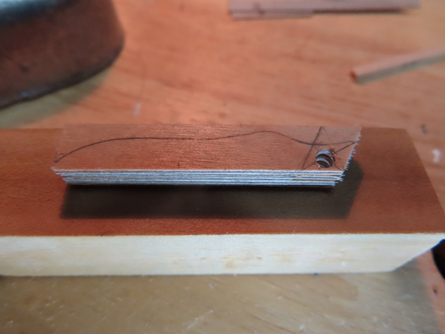
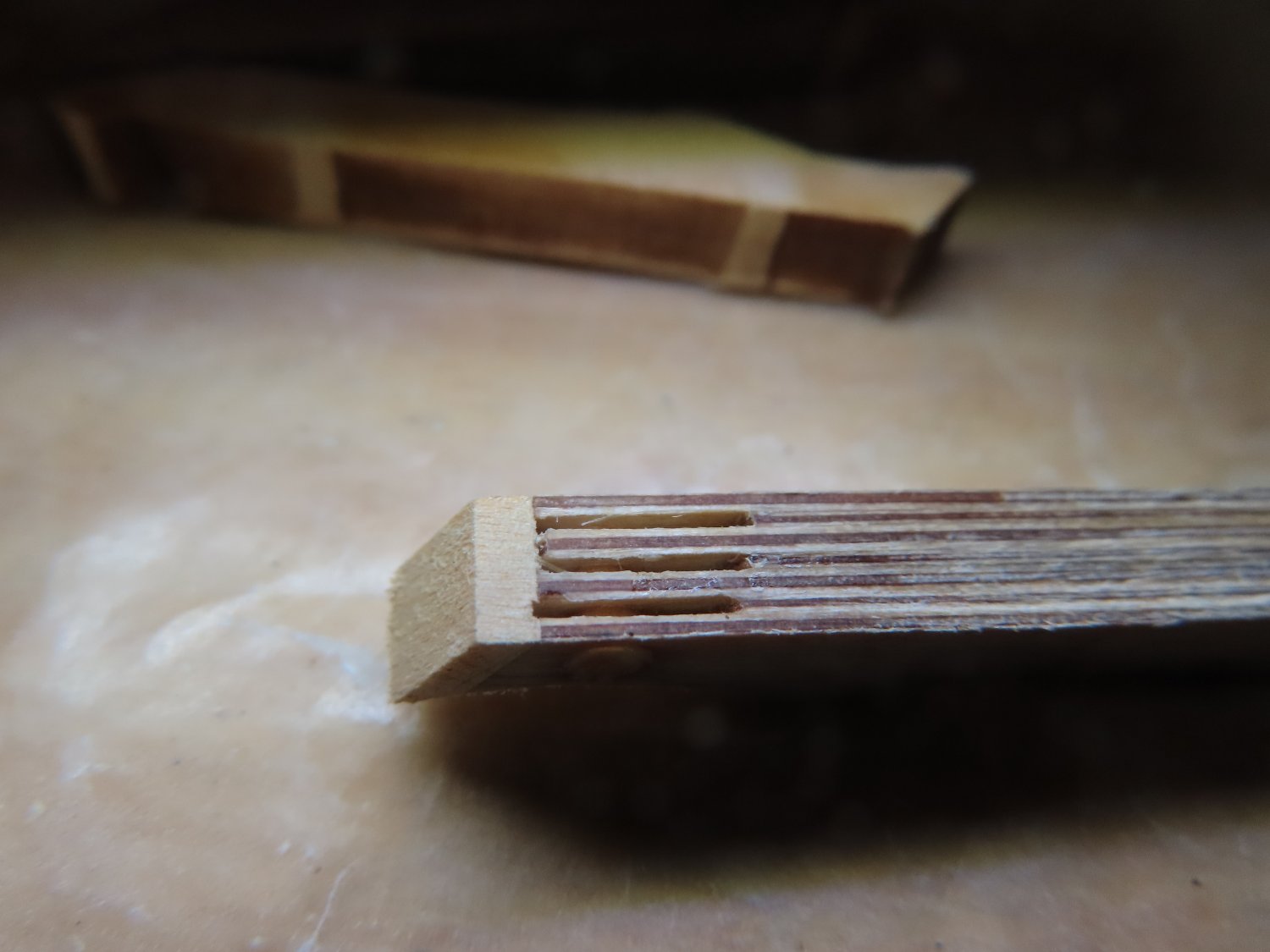
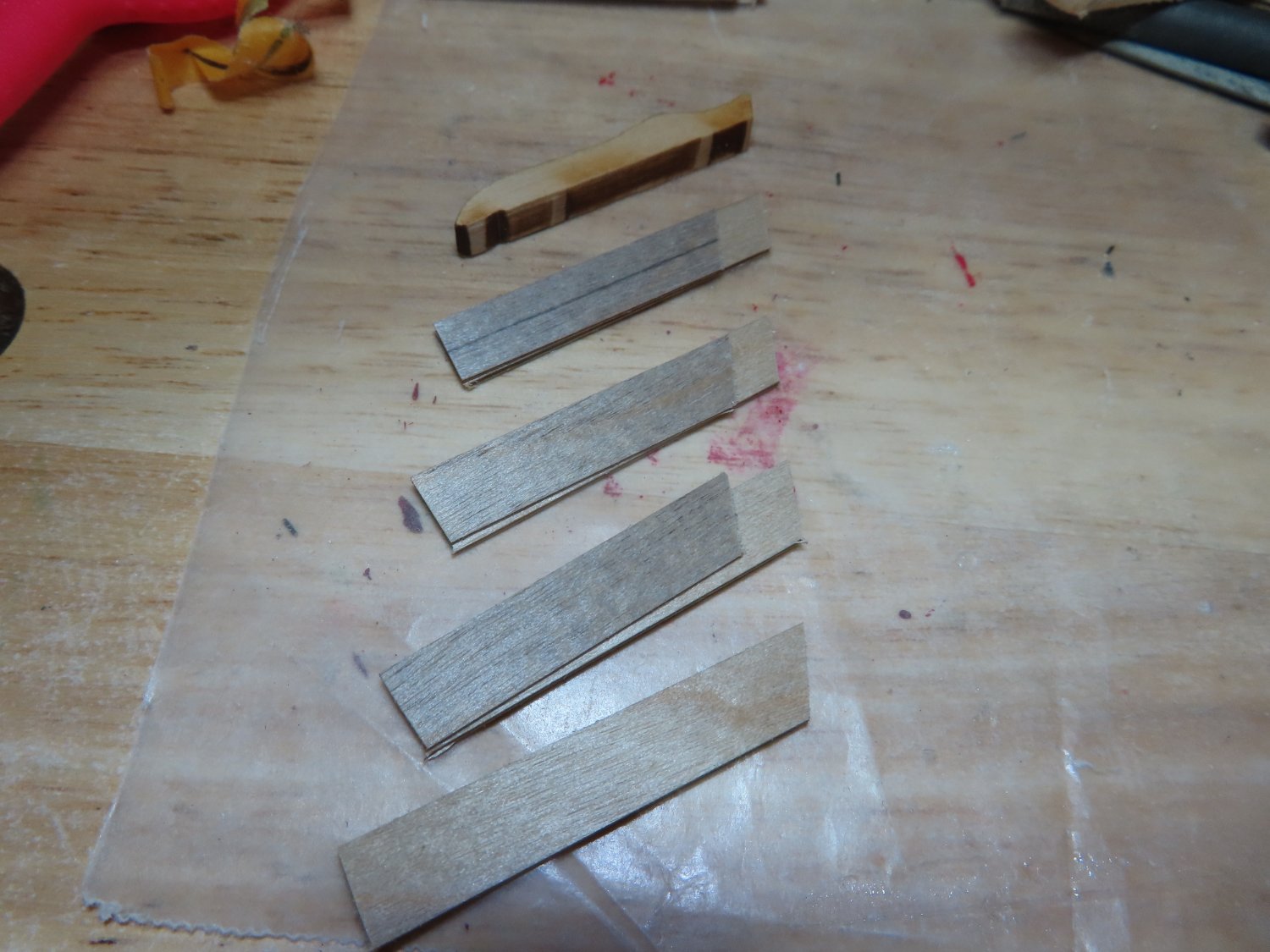
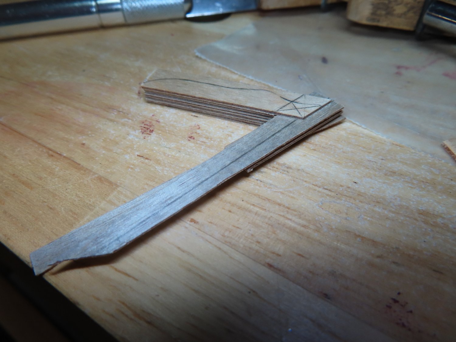
Using the kit supplied raw shape catheads, stock 1/32” and 1/64” birch plywood was cut to size, 4 pieces of 1/32” and 3 pieces of 1/64”. with one end sliced 60° to the long sides. Also, the 1/64” pieces were also sized ½” shorter length than the 1/32” pieces. The pieces were assembled, clamped, and glued with wood glue. Temporary 1/64” spacers were added to maintain separation during gluing.


-
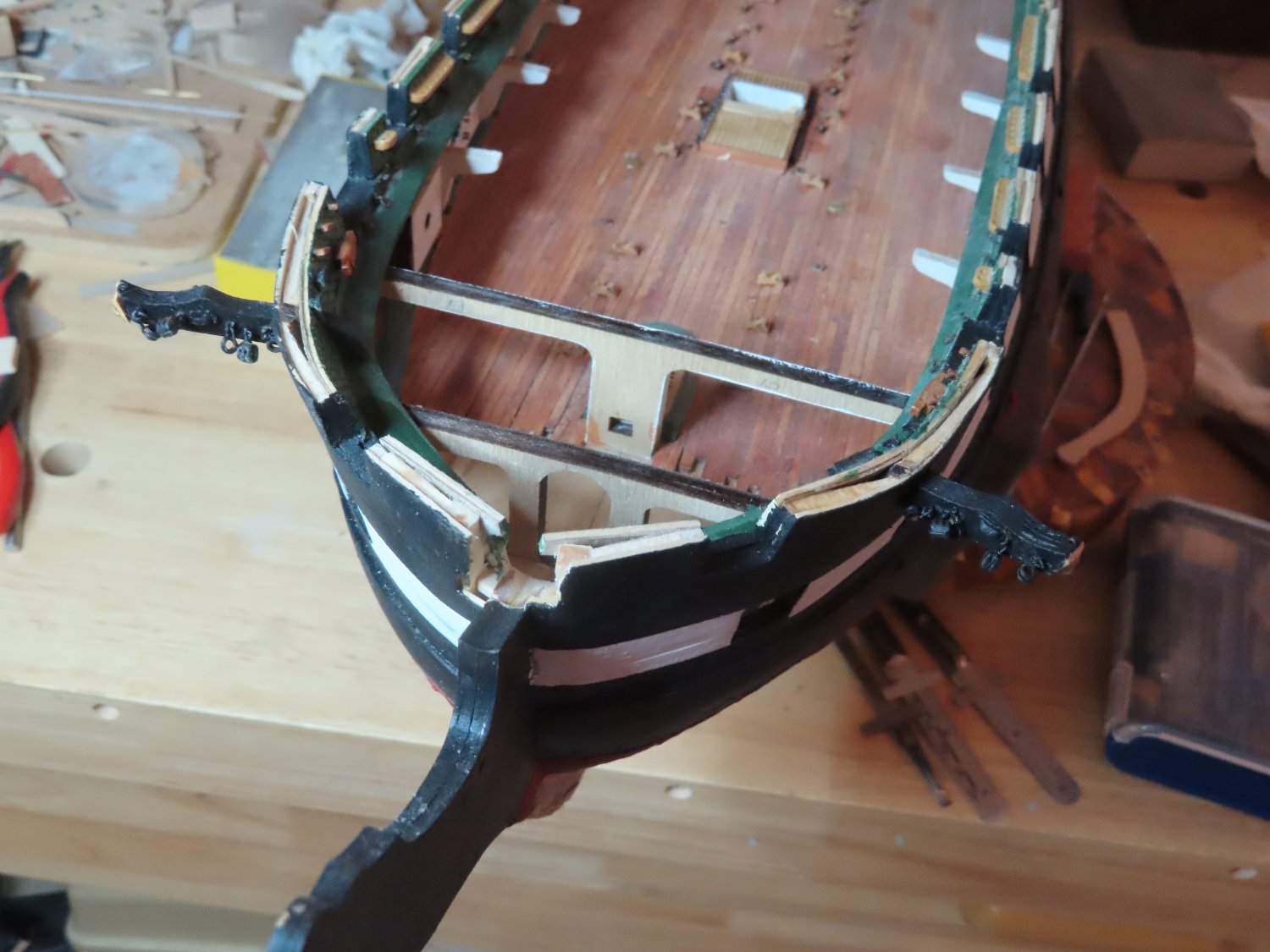
After studying the photographs long and hard, the practicum, and other build logs, I’ve concluded that this going to be a bitch. The problem I see is that there is not a straight line anywhere, the plans provide no explanation as to how to fabricate the bow rails. The practicum does try to show how its to done, but for my skills, I needed more details. What I did realize is that I needed to install the catheads now because the head rails tie into them.
Catheads
If I were following the practicum religiously, which I’m not obviously, the cathead would have already been installed by this time. I had planned to install them when I started to work on the spar deck. The kit provided the basic raw cathead shapes which I used to ensure that I made the cathead hull openings the proper size earlier on in the build.
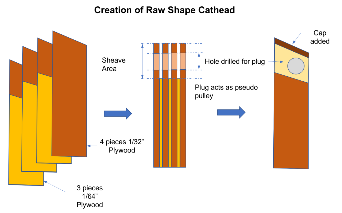
At the outside ends of the catheads, there is a triple sheave. Mr. Hunt in his practicum simulated these sheaves in the kit provided catheads by drilling two holes per sheave at the outer end of the catheads and carved a groove between each pair to give them the appearance of the imbedded pulleys.
The catheads do not extend out from the hull horizontally, but at an upward angle. This requires that the triple sheeves openings at the end of the cathead must be drilled at angle, so they are vertical when installed. Drilling six holes perfectly parallel at an angle for each cathead is beyond my skill set or available tools at my disposal. Instead, I made the holes by layering 1/32” and 1/64” birch plywood using the plan below. I chose to alternate two thicknesses of plywood because the final cathead must be 3/16” wide. Seven pieces of 1/32” plywood is too much. With the addition of glue, the combo plywood assembly worked out exactly 3/16”.
-
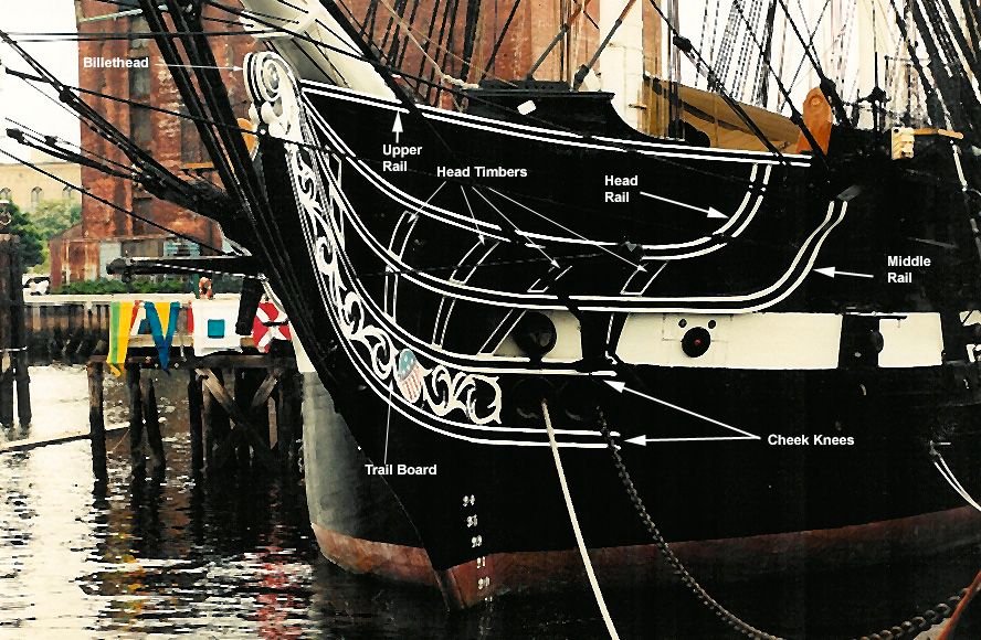
Bow Details
it’s time to work on the bow details, Chapter 8 of the practicum. Taking a deep breath and I jumped in with both feet. The practicum instructions provide an annotated image of the bow with the pertinent nomenclature.
-
Greg, there is no whaleboat planking. The boat hull surfaces are painted which would erase any evidence of the planks. If you look at pictures of the real whaleboats, they are smooth as a baby's butt 😁. Hope this makes it easier for you.
Jon
-
That was an awesome step. My heart would have been in my mouth if I did it. You are going to have a fantastic model when you're done.
Jon
-
I'm sorry, I meant to give you the the earlier post where I made the scuppers as well. Take a look from Post #546.
The air ports (round holes) were precast Britania metal provided by the kit. I didn't like the precast scuppers. They were made from brass a tube which were sliced like a loaf of bread. Then they were flattened into "race track' shape with a vise. The scuper lids were cut from brass plate and CA glued.
Jon
-
Here's an image of the airports and scupper. Model Shipways' plans show the locations of the airports and scruppers. If you have no luck finding and image/plan that shows these locations, PM me and I will scan my plans for you. BTW, I made my own scuppers, not that you can see them from a foot away at 1:76.8 scale (see my blog starting at post #625).
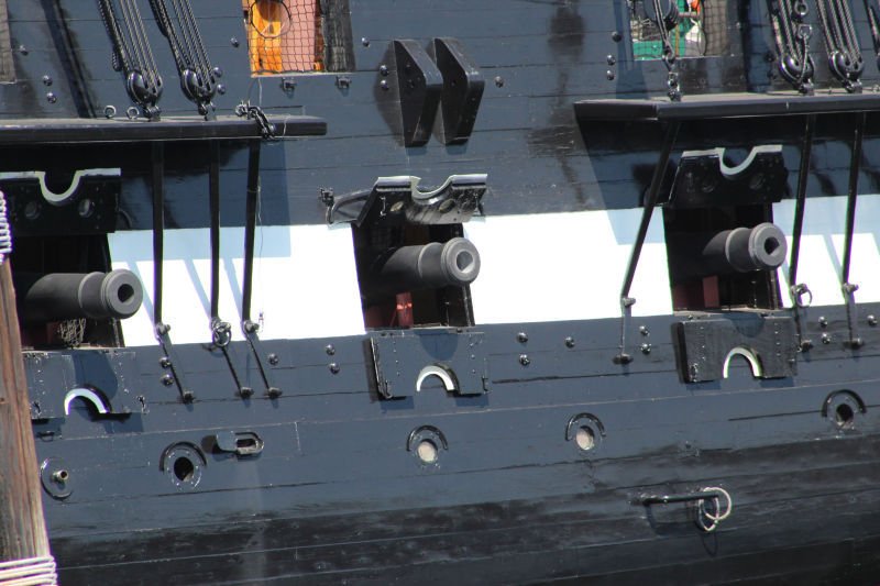
-
-
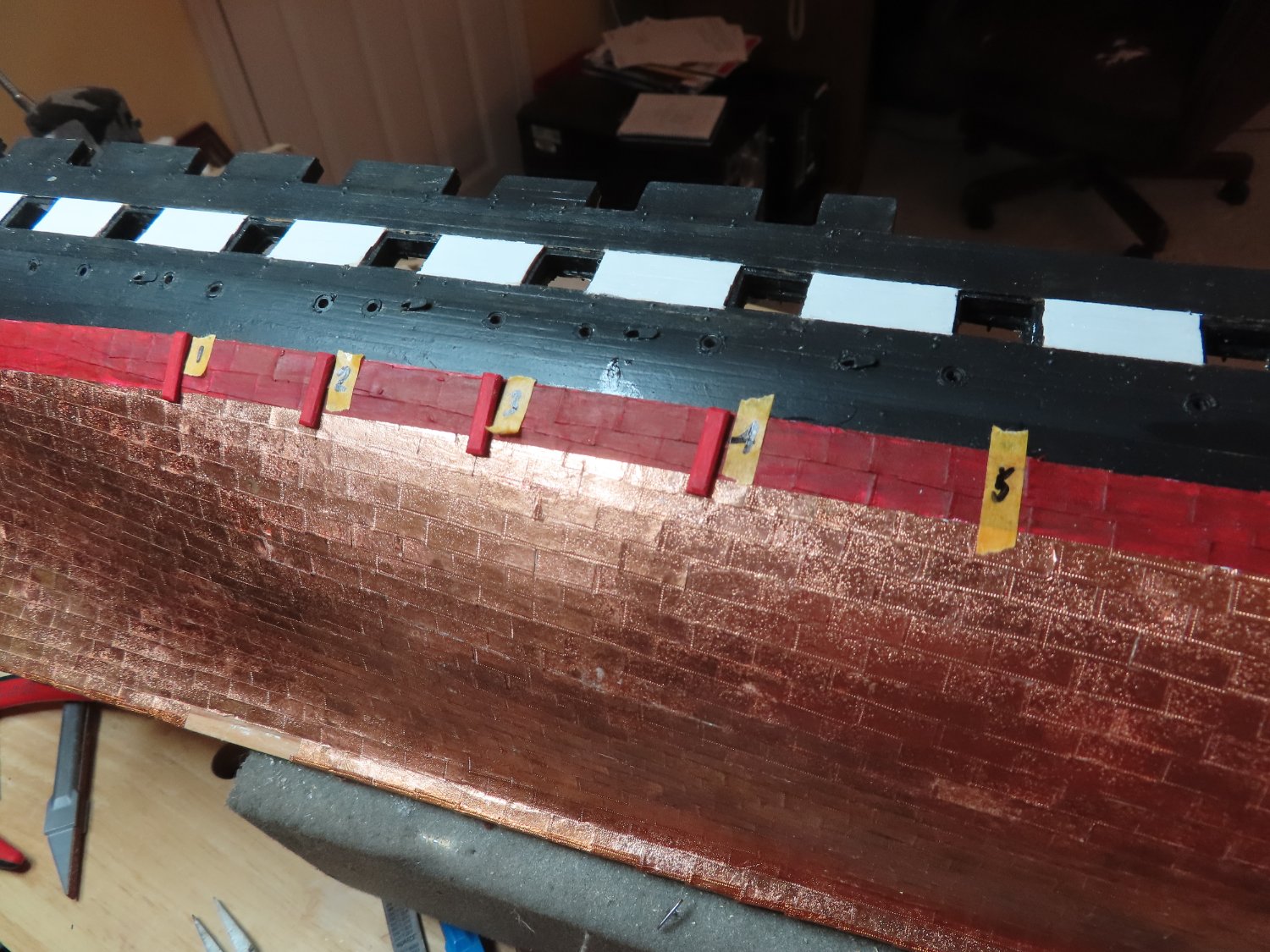
The results of my efforts are shown below.

- Nunnehi (Don), Ryland Craze, KurtH and 3 others
-
6
-
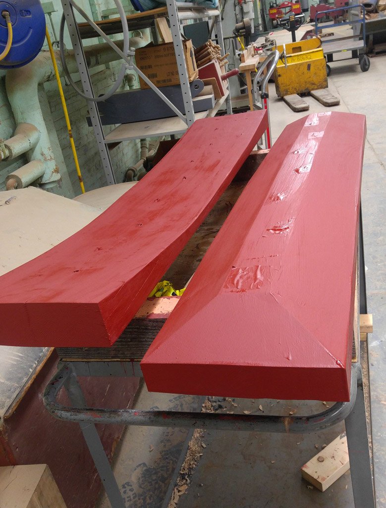
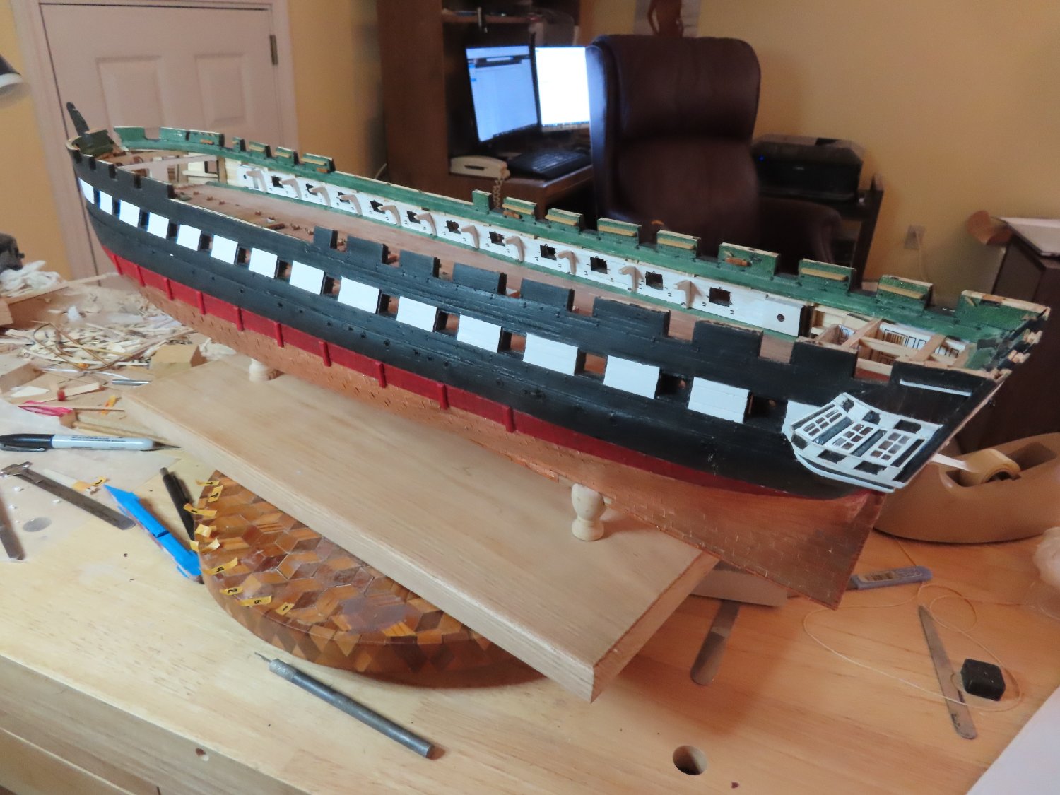
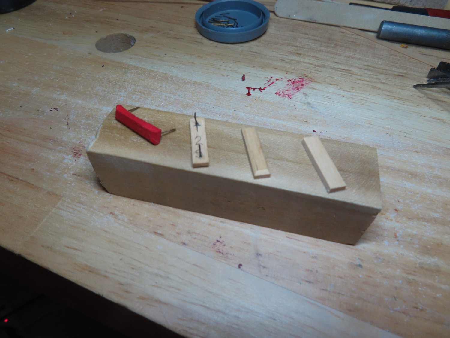
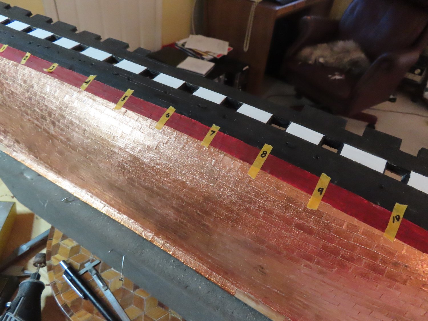
Using 5/32” x 1/8” stock boxwood, twenty pieces were cut 21/32” in length. Boxwood was chosen over basswood because it holds a very fine edge. The chamfers were created using a sanding block. I didn’t trust myself to cut them using an X-acto knife as Mr. Hunt did in his practicum. Then, using a drum sander bit on the Dremel rotary tool at a slow rpm, the hull face side was sanded down every so gently to match the contour of the hull at each position. The fenders were identified on the inside face with an arrow indicating UP orientation, S or P for the proper side, and the position 1 -10. I just arbitrarily made the aft most position No. 1. Using left over metal wire trimmed from eye bolts and other hardware for the pins, holes were drilled into the backside of the fenders and the pins were CA’d into the holes. Before installation, the fenders were painted red. Pressing the fender onto the hull, the pins left an impression indicating were I had to drill holes into the hull for the fender pins. The fender locations were premeasured and indicated on the hull with paint trim tape.


-
I followed the practicum for the most part in constructing 20 fenders, 10 for each side with the following modifications:
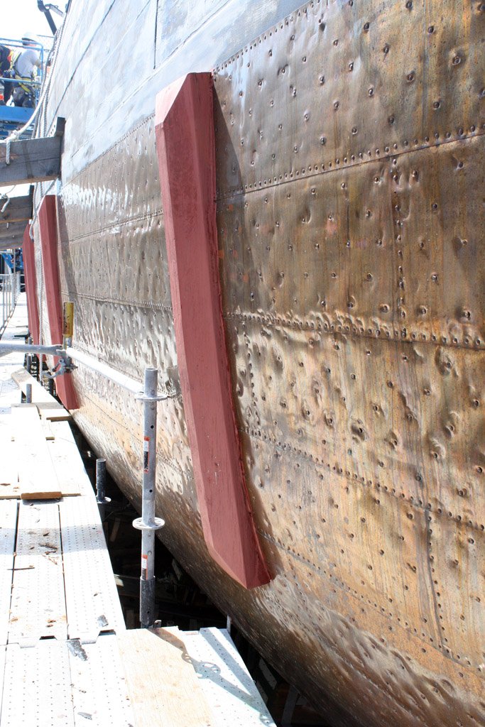
- The MS plans, the practicum, and the pre 2015-17 restoration photos, show the fenders are chamfered on the vertical sides and top edges, not the bottom. According to the 2015-17 restoration photographs, all four sides are now chamfered.
- The practicum left the fenders as bare wood, but the photographs (even before the 2015-17 restoration) showed they were painted the same color as the red stripe.
- The practicum would have you just simply glue the fenders to the hull. I added two pins each fender for a more secure attachment.
To be fair, at the time the practicum was written sometime in 2014 I believe, there were very few images available showing details of what the fenders looked like on or off the ship. I’ve only located these images from the 2015-17 renovation shown below. Moreover, when the ship is afloat, most of the fenders are not visible as they are hidden below the waterline. And, for some reason, very few images with any detail are available even today (at least on Google) when she was in dry dock. I guess they’re not a very interesting subject to photograph.
- Ryland Craze and CiscoH
-
2


USS Constitution by kmart - Model Shipways - scale 1/76
in - Kit build logs for subjects built from 1751 - 1800
Posted · Edited by JSGerson
K-mart, I'm just starting my head rails and I am studying everyone build logs to get the best methods. Yours is on my list.
Question #1, here as some photos from the 1927 restoration which clearly show the boomkin is horizontal and parallel to the waterline.
Question #2, The white piping is raised slightly above the base. Some people use white painted 1/32" x 1/32" wood strips, others like shown in Mr. Hunt's Practicum use vinyl strips. Technically, if you look closely, the piping is painted just on the surface.
I hope this is what you've been looking for.
Note: You will also see that the cathead and bumpkins are moved aft in the 1927 images from what is shown in the plans, which supposedly are based on the 1927 restoration.