HOLIDAY DONATION DRIVE - SUPPORT MSW - DO YOUR PART TO KEEP THIS GREAT FORUM GOING! (Only 13 donations so far - C'mon guys!)
×


JSGerson
-
Posts
2,611 -
Joined
-
Last visited
Content Type
Profiles
Forums
Gallery
Events
Everything posted by JSGerson
-
 OK, according to "Anatomy" there is a line on either side of the davits with block and tackle (which you haven't installed yet) that would provide the tension to spread the davits. The line in between (which you have installed) goes into tension limiting the spread. That makes sense. Reklein - I thought the bags held ropes that would be used to drag behind the boat as a safety line or to throw to a man in the water. I don't know, we may be both wrong. Jon
 -
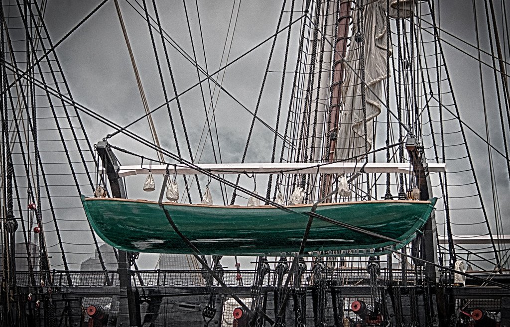
Looking at a contemporary image, I see a black rope seized to each davit just like you did but it also has white bags suspended from it. The white wooden spreader joins the davits at the elbow. It's function appears to be to keep the two davits at their proper spacing which means it has to take compressive forces as well as tensional forces. A rope "spreader" does not make sense to me. Are you sure your rope "spreader" is not the one suspending the bags? Confused Jon
-
How do you know the ship had a dedicated chair for the barber? And don't forget, the barber of those times was many times, the ship's surgeon who did the "medical" procedure of blood letting (hence the red & white barber pole). I would imagine, any chair that was available was used; but I talking off the top of my head...no research. Jon BTW, I found no pictures or plans
- 742 replies
-
- 6
-

-
- constitution
- frigate
- (and 1 more)
-
Thanks for the invite, I would very much like to see your shop. I also got a PM recently from Canute who lives in Hendersonville, NC, and Chris Coyle who lives the Greenville/Spartanburg NC area also suggesting an occasional meet since none of us have had the opportunity to join a local modeling club. Maybe we could work something out. And yes, the ship's boats are fun to do especially when there are nice detailed plans from which to work from. I enjoyed making the ship's boat from Model Expo's mini kit boat, I just justed couldn't wait and started Conny's boats first. Jon
-
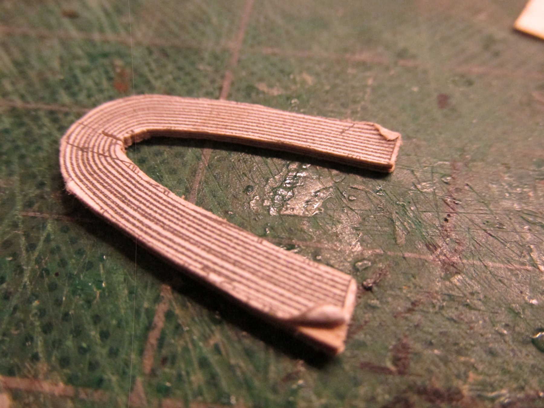
I took a different approach for my Rattlesnake, I cut the curve pieces directly, no bending required. See starting at post 330. Jon
-
USS Constitution (Mamoli 1:93) What to do?
JSGerson replied to Techsan's topic in Wood ship model kits
If I might put in my 2 cents, it ultimately comes down to you. Are you satisfied with what you have? If not, it will bother you like an unreachable itch. If you're not satisfied, trying to continue the build would be like finishing a house on a weak foundation, you just won't to the model justice. If you are happy with what you got, maybe all it needs is just a tweak or two and then you can move on and complete the build and feel the satisfaction of a job well done. It is difficult to judge the quality of the model from just a few pictures so you are the ultimate judge. Don't forget, the model has waited 22 years for you, so there is no rush to complete it "quickly." Take your time, assess what's good, good enough, barely passable, and must do over, then go from there. Jon -
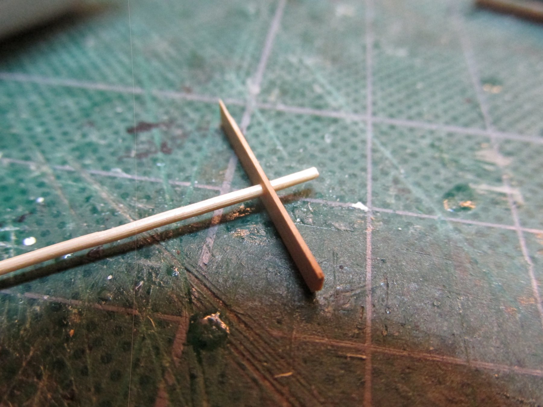
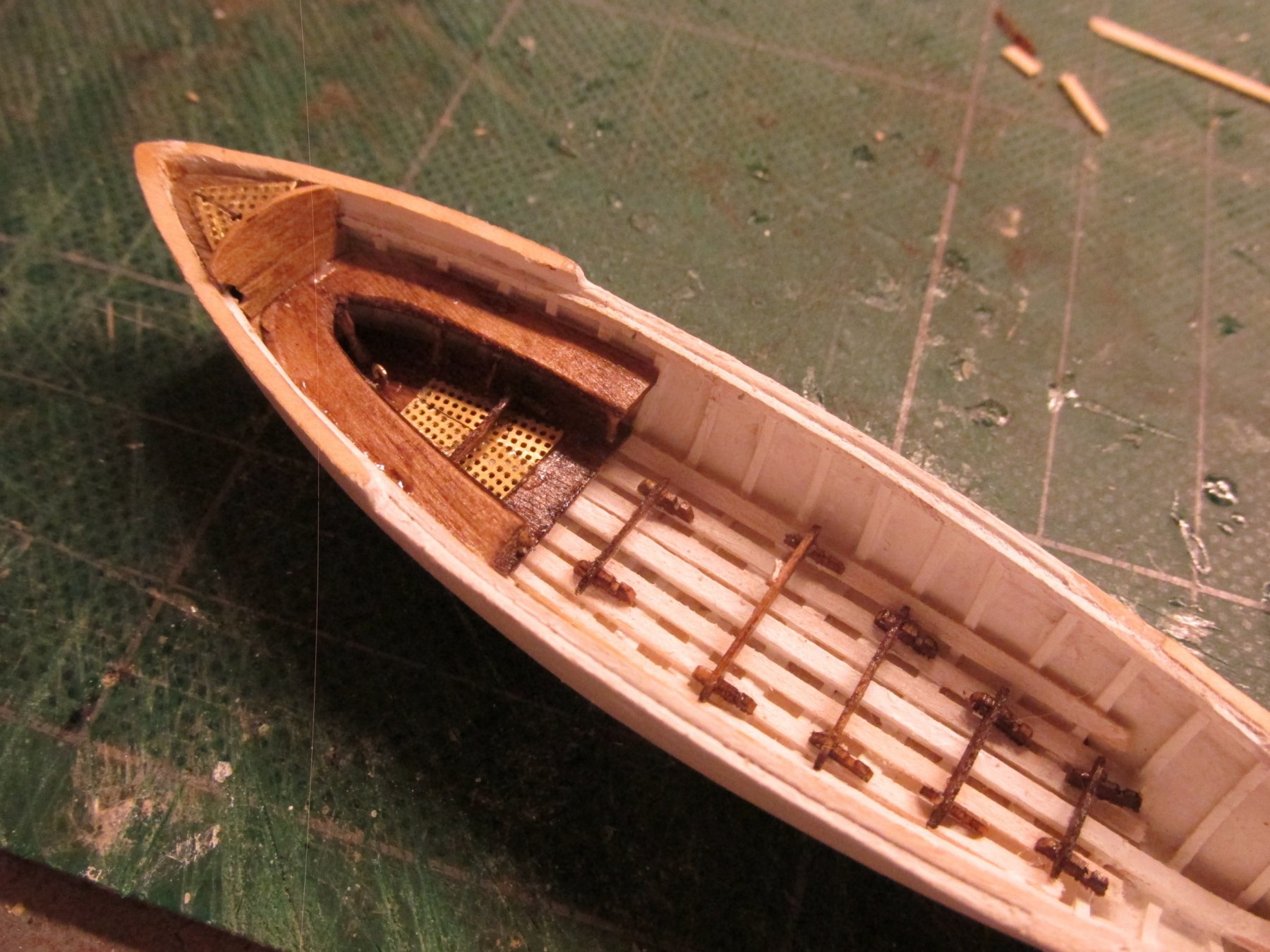
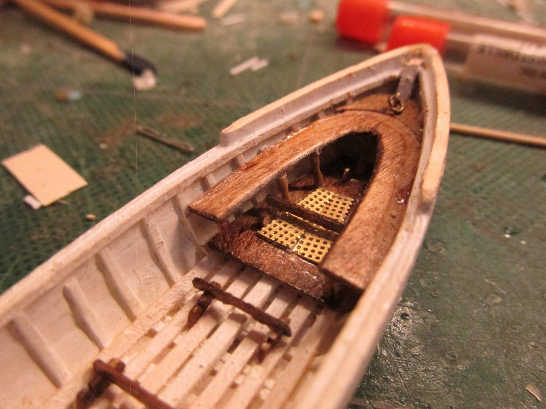
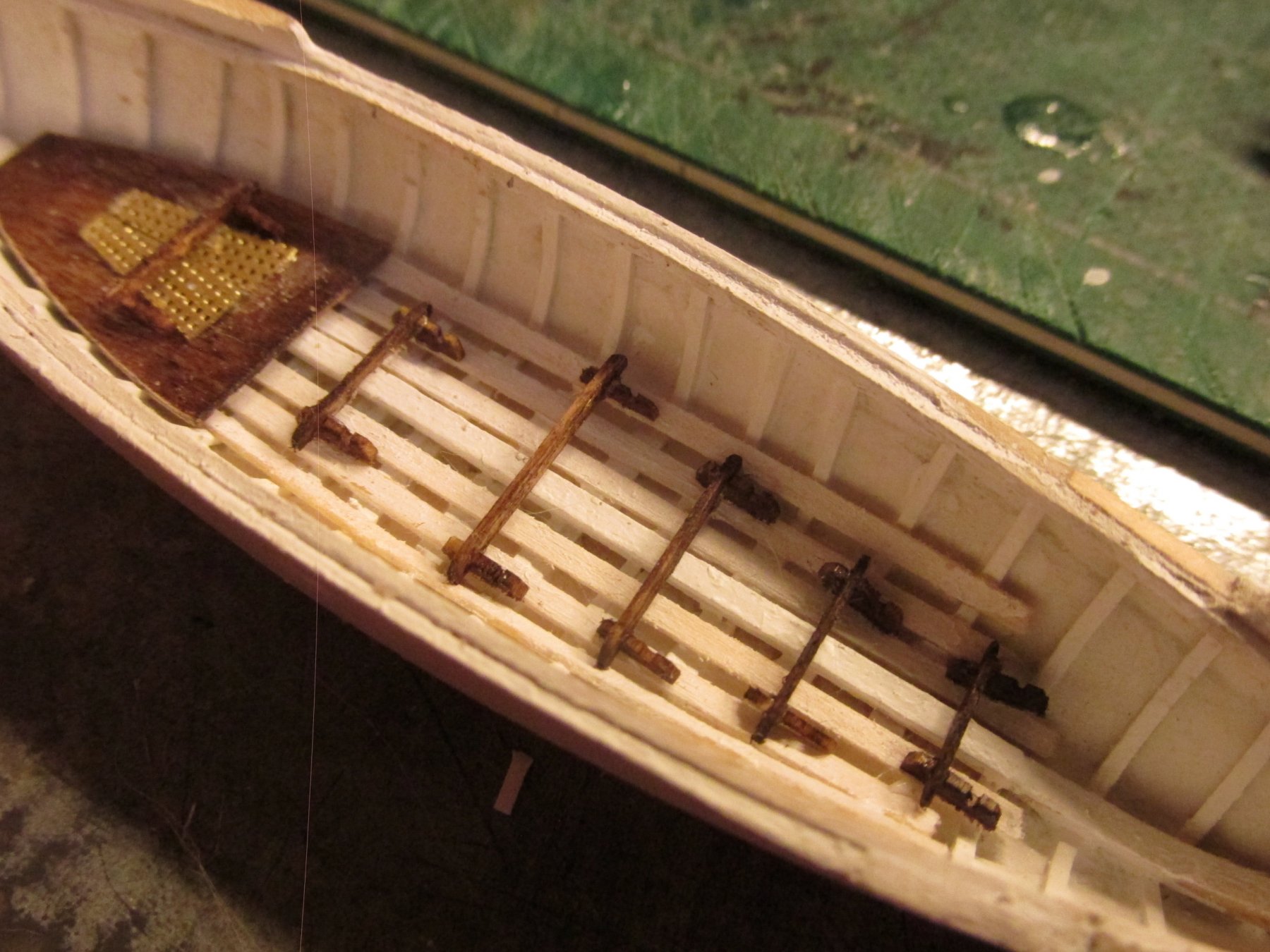
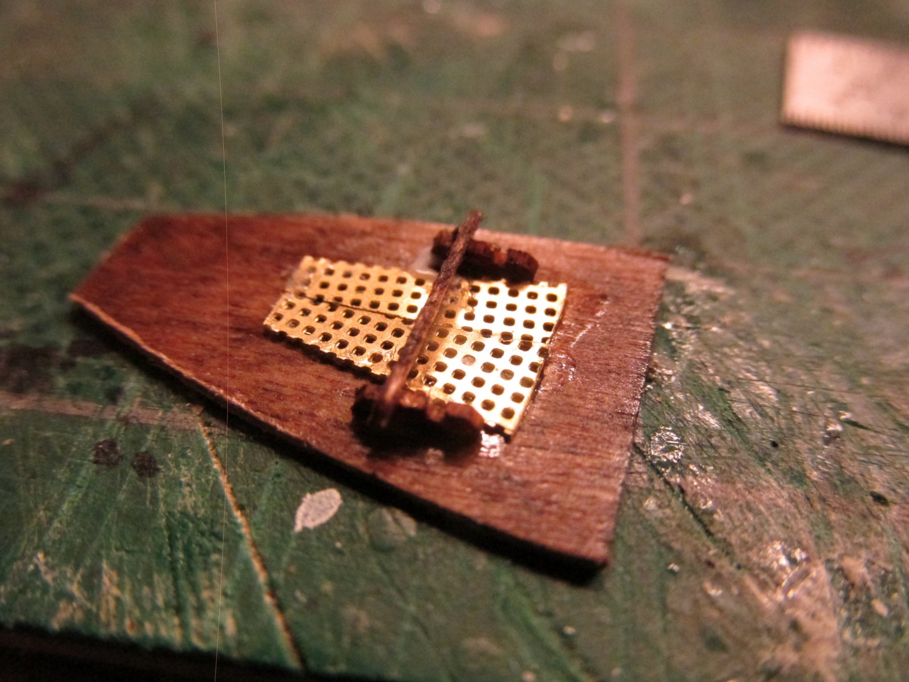
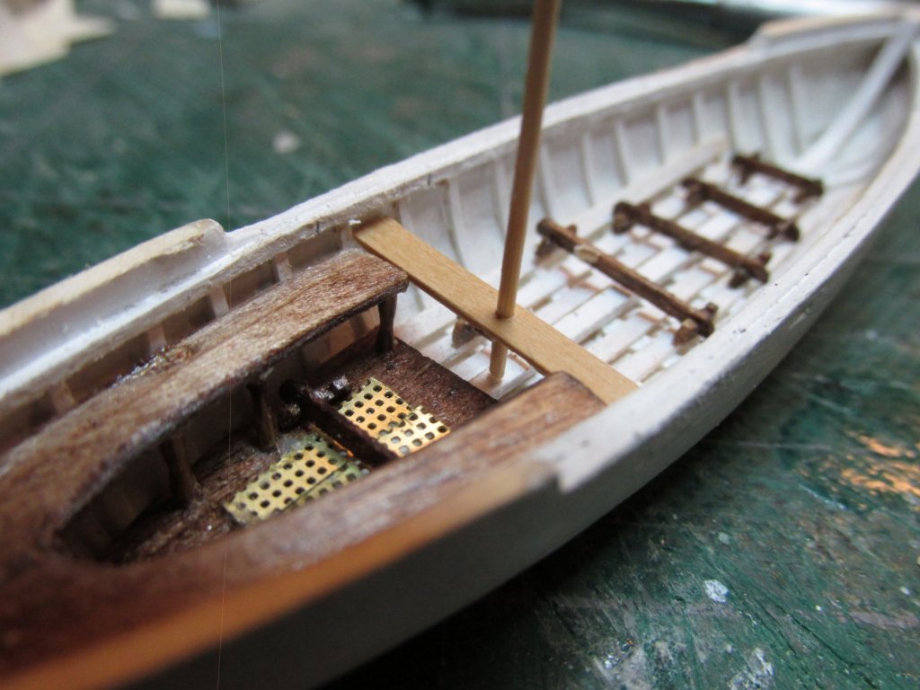
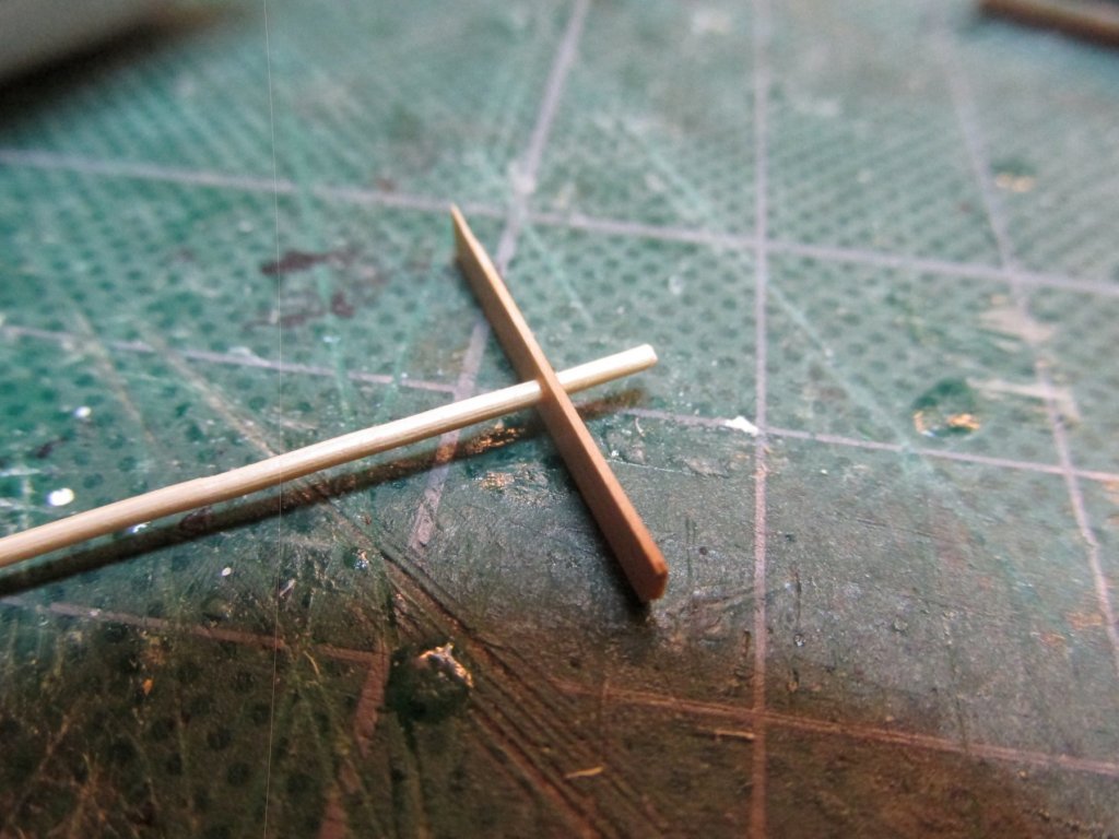
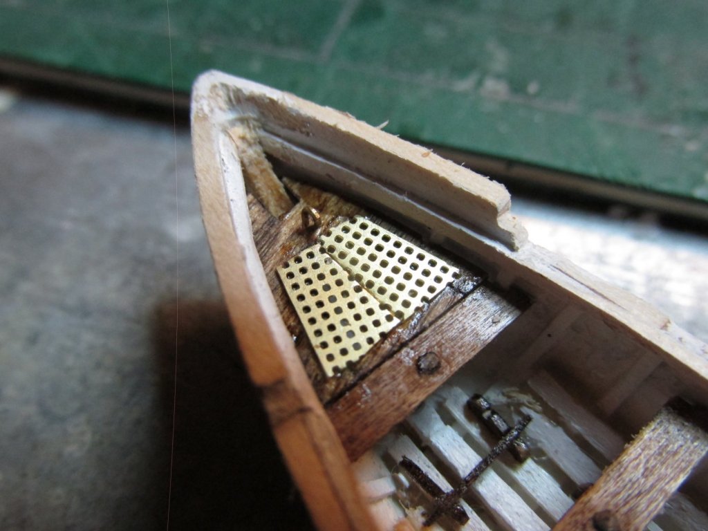
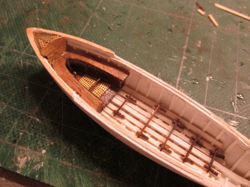
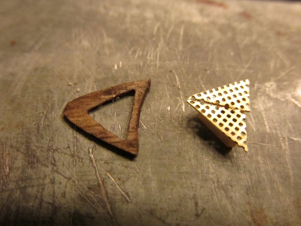
It’s been a number of weeks since I posted. I was in Florida for a week (again) with Mom at her condo; she celebrated her 99th birthday. My sister and I alternate about every 6 -8 weeks or so visiting her. The night before I drove the 600 miles back to South Carolina, I received a text message from my cat sitter – my roof was leaking. After I got home, it started to rain again and in buckets. Well, my roof leaked again. Luckily the down pour lasted only 20 minutes, but I collected a half gallon of water in my attic. To make this saga short, well shorter, the leak was from one of two Dish satellite antennas which was mounted on the roof for the last 10 or 11 years. Eight years ago, I had a new roof put on which covered the satellite mount which made the mount even more water proof, until it wasn’t. The other dish was mounted on my chimney. The reason I had two was they worked in tandem so that between the two, they could see the three satellites. My house is surrounded by tall trees…lots of them. The satellite company was supposed to upgrade my service which would have made the roof antenna obsolete because the new system couldn’t use a second dish… provided I had the trees trimmed. That was supposed to happen once I returned from Florida. I guess that roof antenna couldn’t wait. Well I got a temporary fix to the roof mounted dish (The mount is now covered with tarpaulin and tape), I had the trees trimmed, so now I’m waiting for the insurance man to set up a permanent fix and for Dish to come and upgrade their system. Oh, did I mention my A/C went out just before I went to Florida? Back to boat building Gig’s Thwarts Working from the Gig’s stern, I started to add the thwarts which were made from 1/64” boxwood. Once I had fitted a thwart to its position, I marked the position of the stanchion and drilled a hole for the 1/32” diameter support. Like the bench seat, I used bamboo which I pulled through a drawplate. The bamboo was inserted into the thwart, position on the boat to get the appropriate length and then glued with CA. The excess was snipped off and filed flush, then the whole assembly was stained. Then it was just a matter of gluing it into place. At the bow, there was the matter of the grating. This time, it did not have to be removable like the stern because the lifting rings were accessible. Once more, I cut the mesh to emulate the diagonal pattern of the grating.

-
It must be nice to have a club...let alone one with members who can get nice goodies. Unfortunately for me, I am a club of one - me. But I do have the NRG which has members who share their vast knowledge. Jon
-
I've done that a couple of times. First with a dentist who gave me the various picks and my most recent dentist who gave me a whole bunch of various burrs. I've yet to wrangle those wonderful little telescope glasses they wear or the pneumatic drill. I understand the old fashion belt driven drills make for a nice carving device if you can find one in working order and cheap. Jon
-
Gregory, if you take a look at xKen's build log of the Conny, you will see how he modeled the stack.
- 742 replies
-
- 11
-
-
- constitution
- frigate
- (and 1 more)
-
Here is a picture from 1890 when the USS Constitution was configured as a receiving ship. It had the stanchions. Jon
- 742 replies
-
- 7
-
-
- constitution
- frigate
- (and 1 more)
-
Yes they are mini-kits...without instructions. The kit does not provide any step by step diagrams or instructions other than some good plans. I'm using the practicum from Robert Hunt as a guide. I've added more than what his practicum shows, but I am using his progression method, i.e. what to build first, second, etc. When I made my Rattlesnake, I bought a little kit from Model Expo for the ship's boat instead of using the provided shell of a boat. Jon
-
I hope you are right. The boats are small, simpler, individual projects, so they're "easier" to do. I can wrap my head around the whole boat. The ship on the other hand....is complicated. I guess I will have to break the ship down into a lot of little projects and take it one step at a time per project. Thanks for your confidence, I hope I don't disappoint.
-
If you made any mistakes on your ship's boats, they are certainly well hidden because I can't see them. I'll be making oars for all the boats and maybe other items as well. I'll see see when I get to that point. Thanks for the praise, I certainly did not expect that when I look at all the other people's work. I hope to do half as well.
-
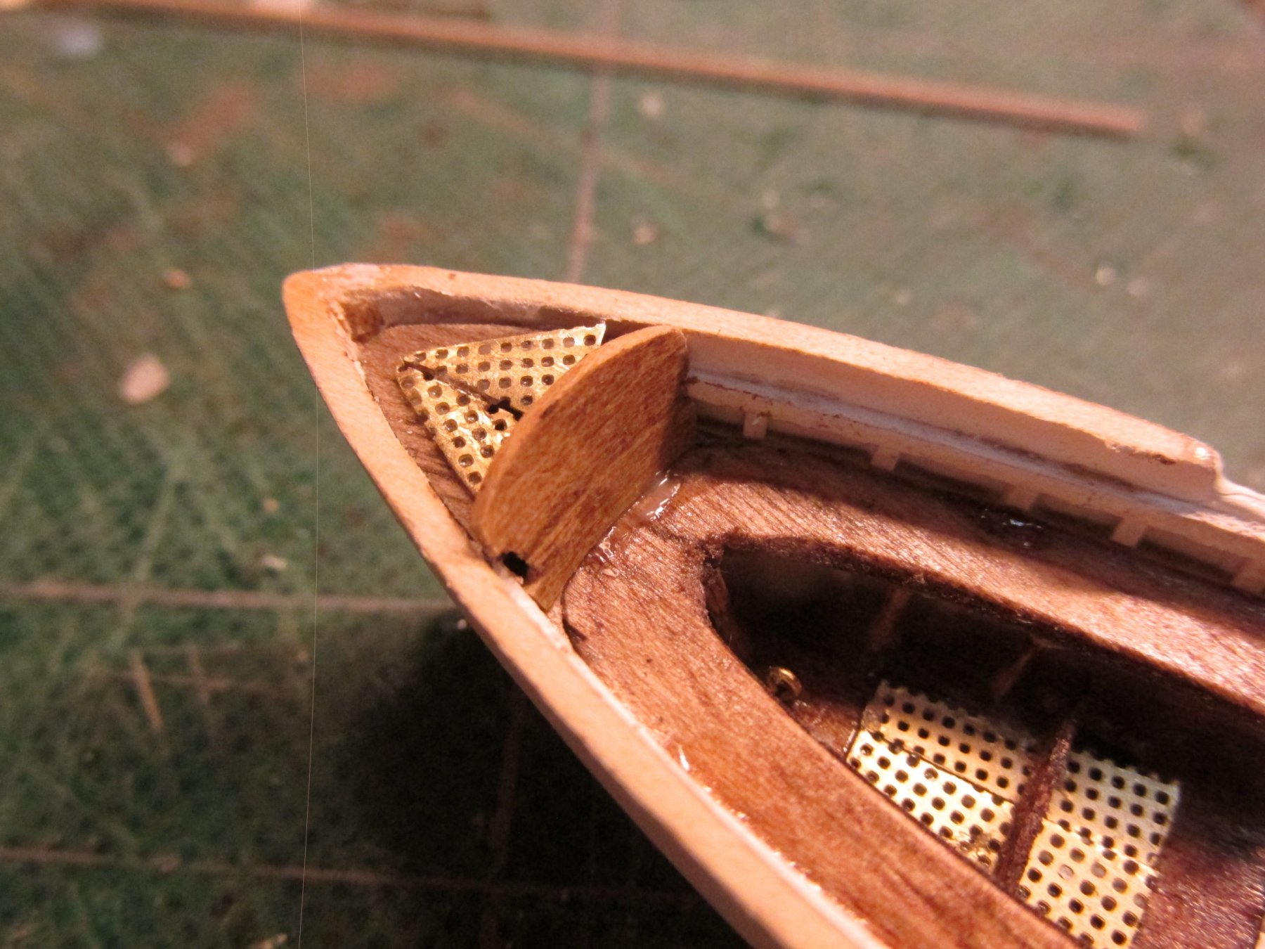
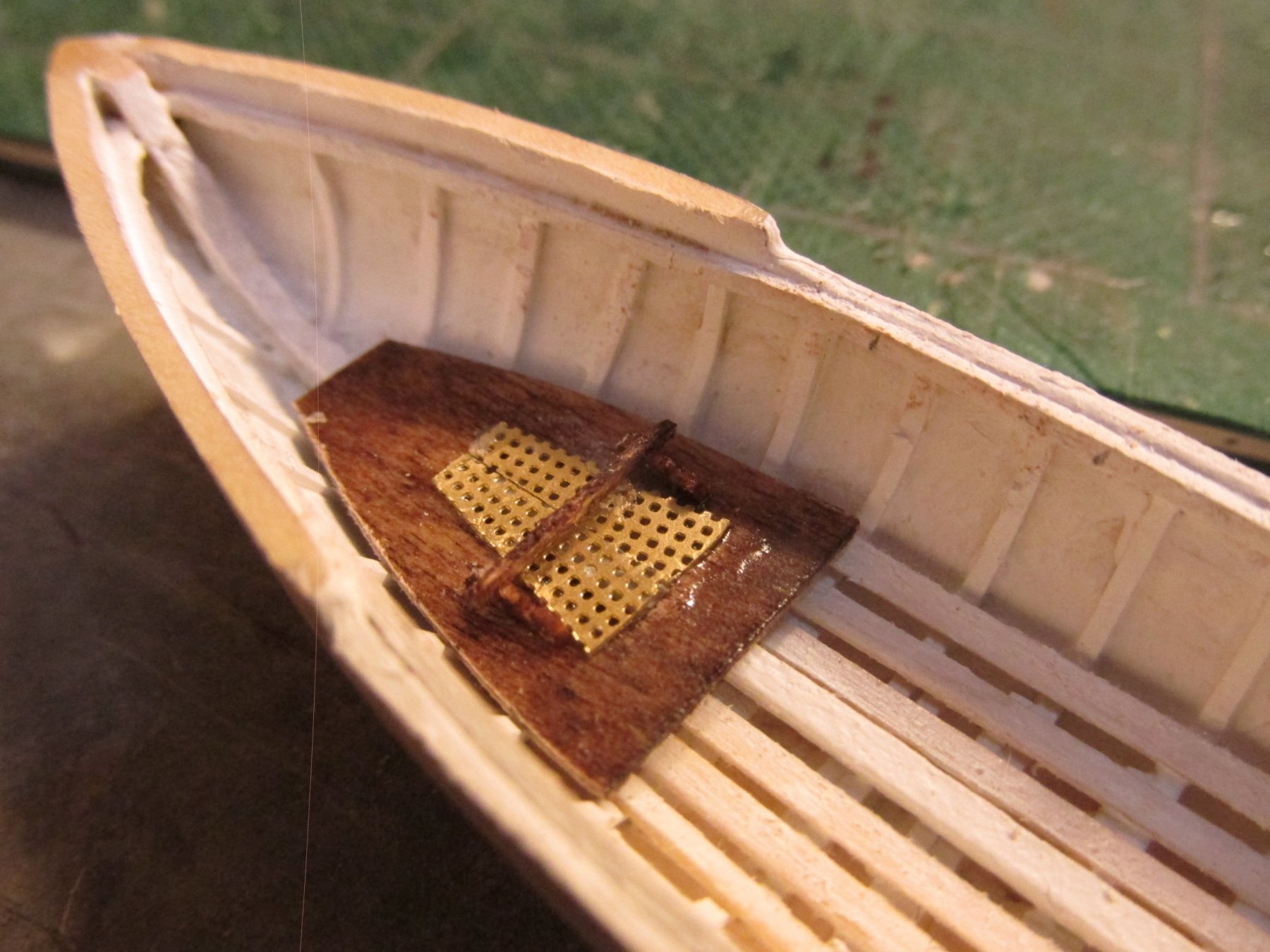
The backboard was made from a single piece of 1/32” boxwood which was bent to a slight curve. Then it was shaped and fitted so that it leaned slightly against the top of the stern compartment. It was glued into place with PVC glue. You may notice that the grating does not quite align properly nor lie completely flat. I did try, but since that is not its final position, as mentioned above, I am not too concerned.The backboard was made from a single piece of 1/32” boxwood which was bent to a slight curve. Then it was shaped and fitted so that it leaned slightly against the top of the stern compartment. It was glued into place with PVC glue. You may notice that the grating does not quite align properly nor lie completely flat. I did try, but since that is not its final position, as mentioned above, I am not too concerned.


-
Interesting... I always thought is was best to work your way up in the same manner as the real ship is rigged. I also try to work from the inside out. Since I value your work methods, I'm curious as to why you found your top down method more practical? I was going to say easier, but nothing is easy on a ship this complex. Are the yard pins temporary or permanent? Thanks Jon
-
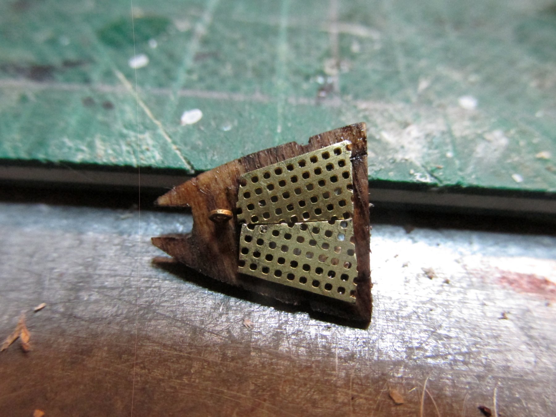
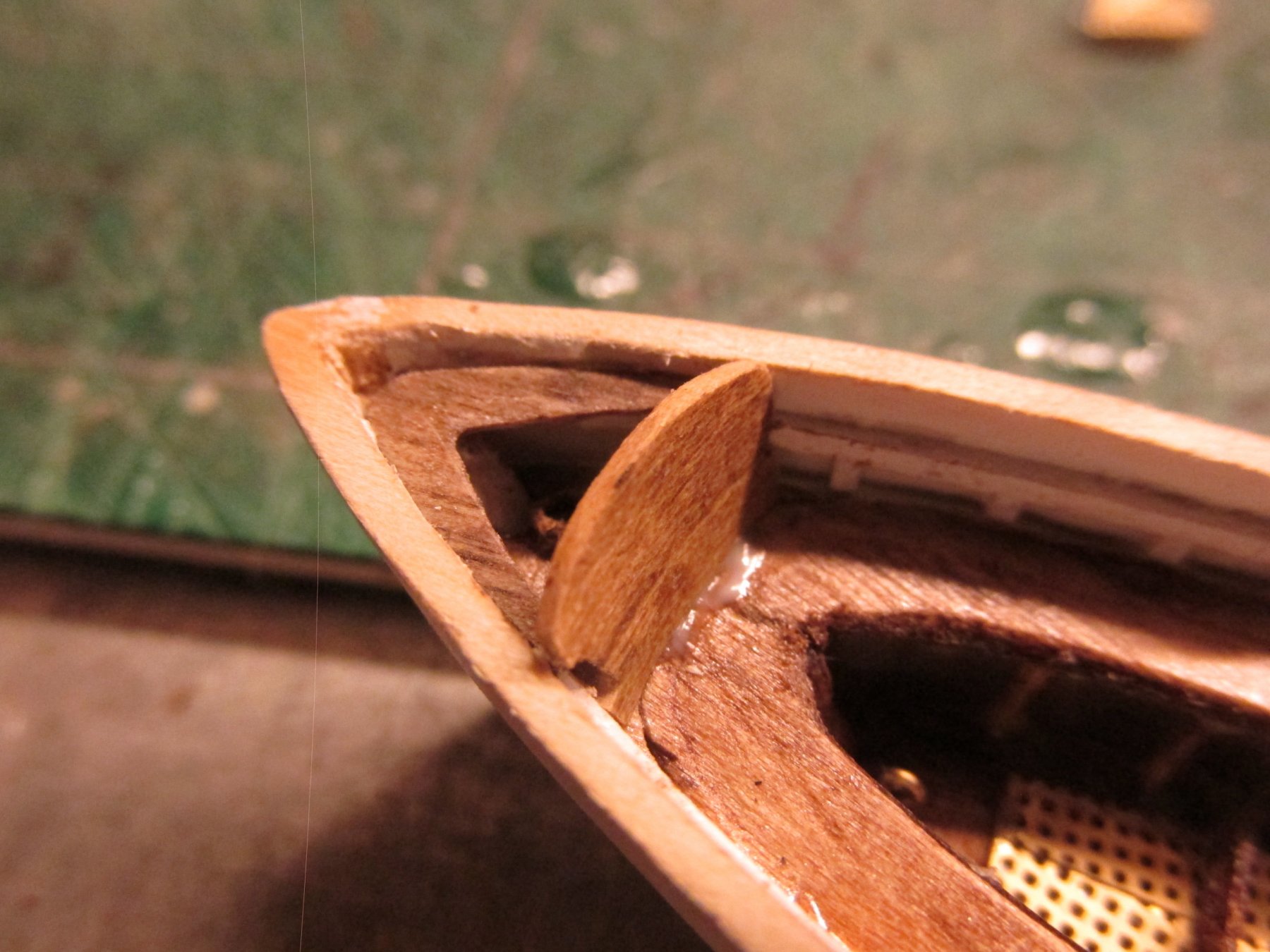
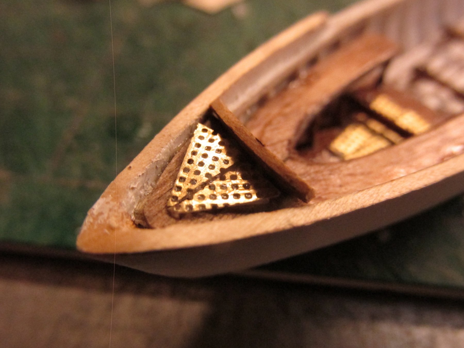
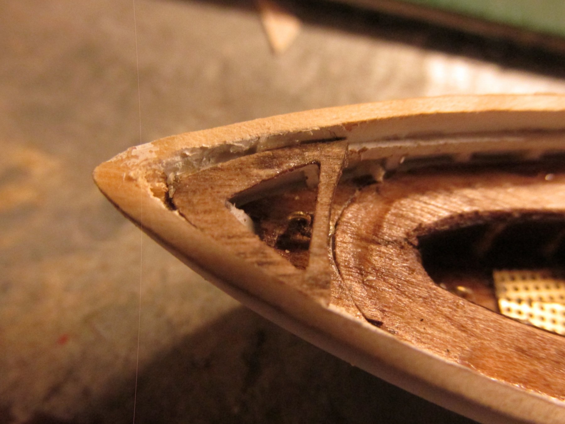
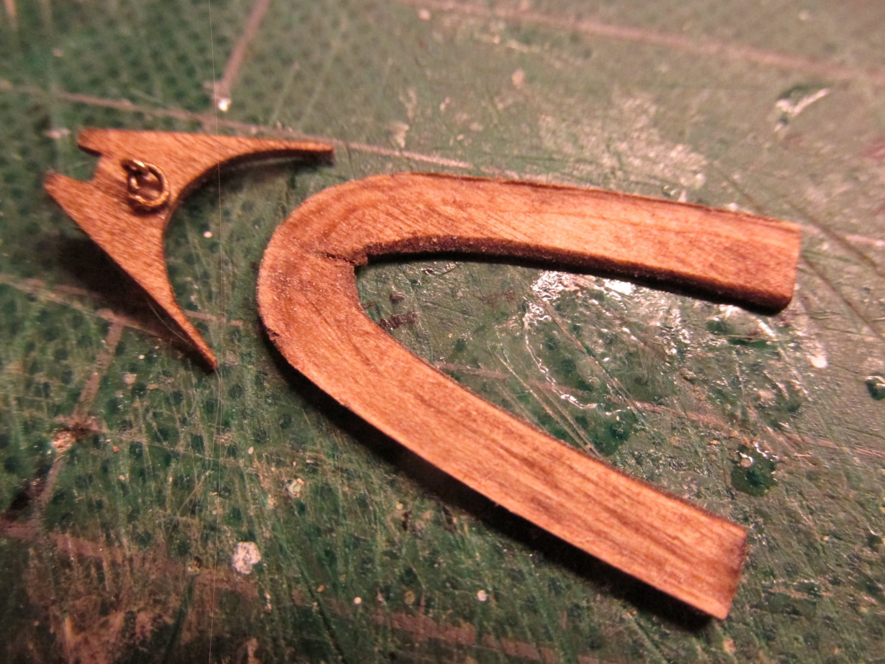
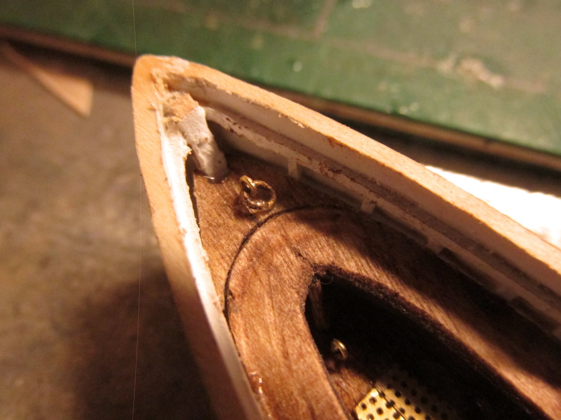
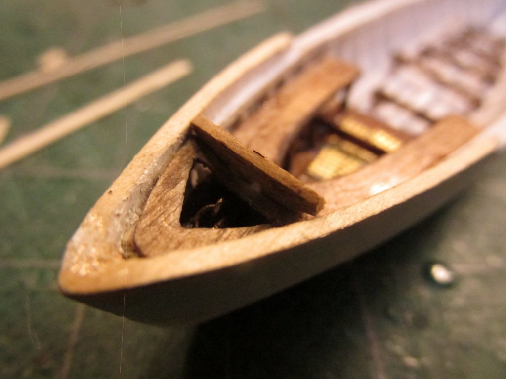
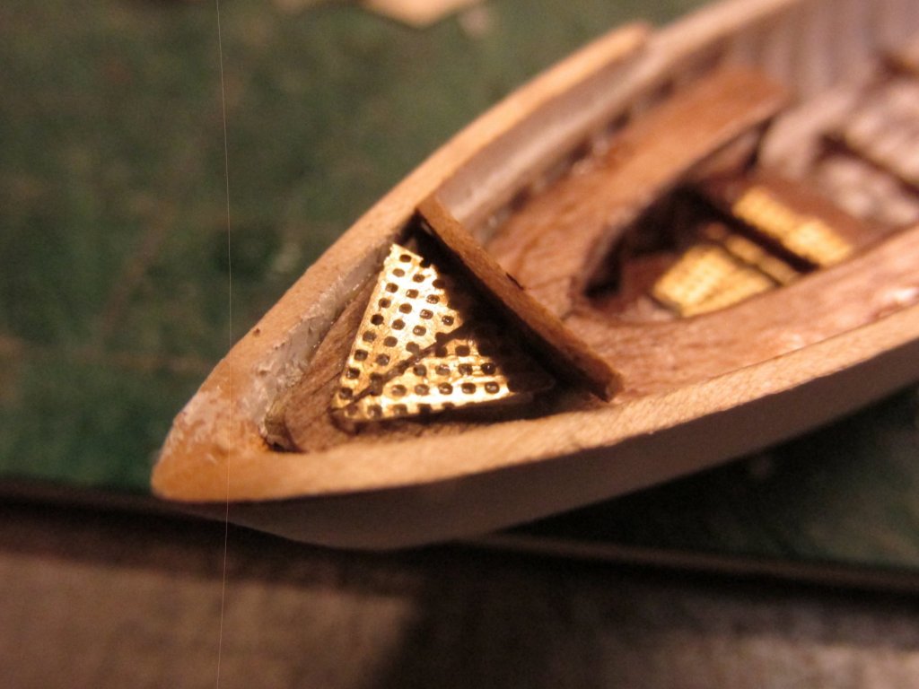
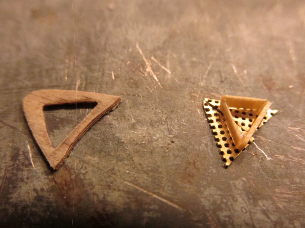
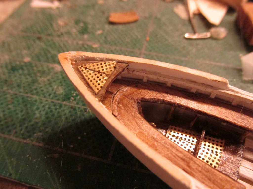
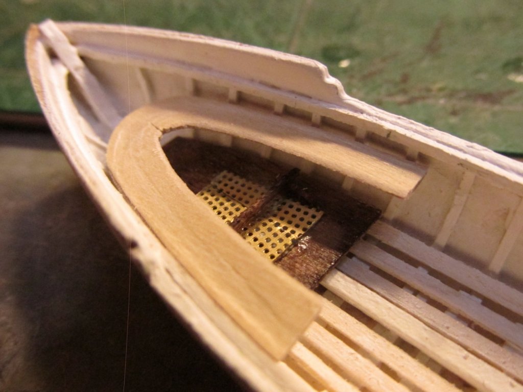
Gig Stern Compartment The last component to be installed in the stern at this stage of the build is the stern compartment with the grating on top. Because the stern lifting ring is inside this compartment, the grating must be removable to gain access. This is made trickier in my case because like the grating in the sole, the brass mesh was split into two pieces to emulate the actual grid pattern. These two pieces must be structurally supported. When the boat is installed on the Constitution model, the grating will be stored inside the boat somewhere. The stern compartment top surface was made from 1/64” plywood for its strength and width. A pattern was made, transferred to the plywood, and cut to shape. The piece was filed to fit into the corner of the stern and to accept the rake of the backboard from the bench seat which has a slight tilt aft. A triangular hole was cut out of the plywood to provide access to the lifting ring. Based on the opening’s shape, a triangle was formed from 1/32” x 1/64” basswood. This will form a lip that will slide into the opening. The two brass mesh pieces were placed on top of the triangle structure. Drops of CA glue were placed where the mesh was resting on triangle. The glue was drawn through the mesh to the wood below and set. After a bit of fiddling, the mesh grating slipped into the opening in the plywood. A this point I had stained the plywood. The last two pictures below show the dry fit. The final part will be the backboard.

-
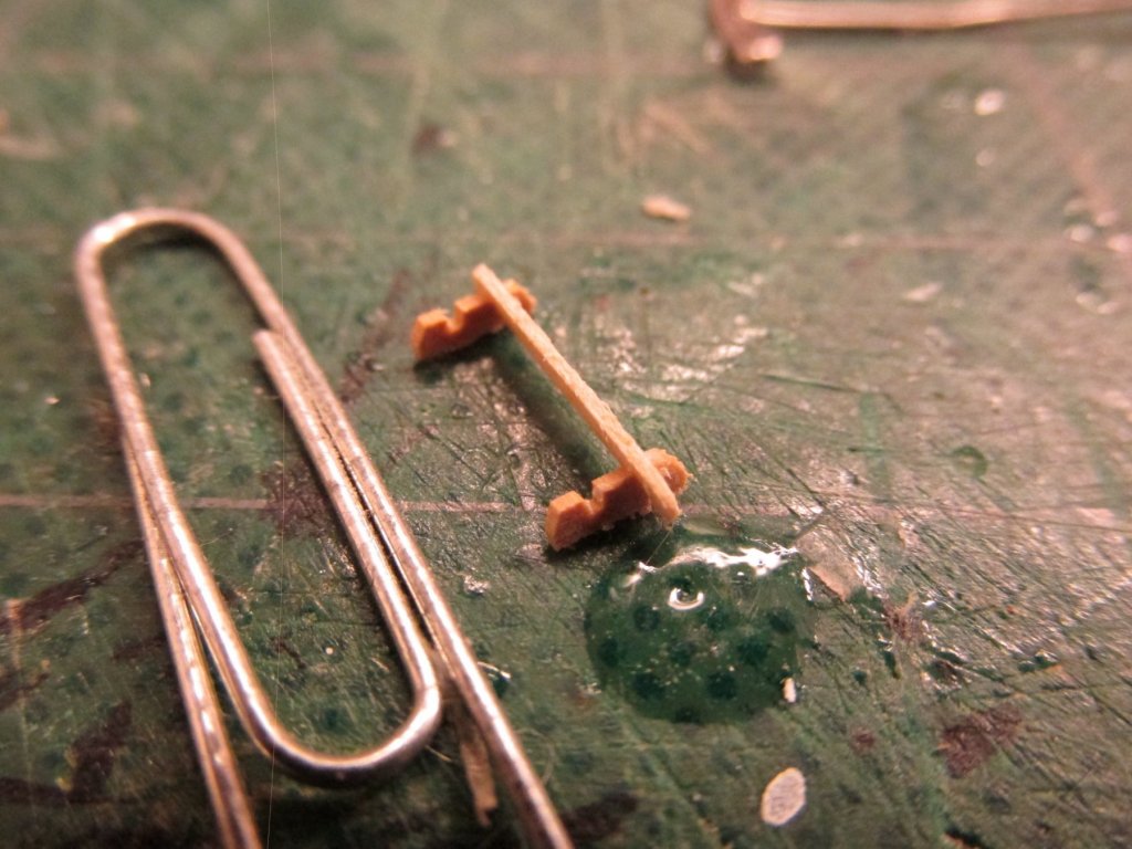
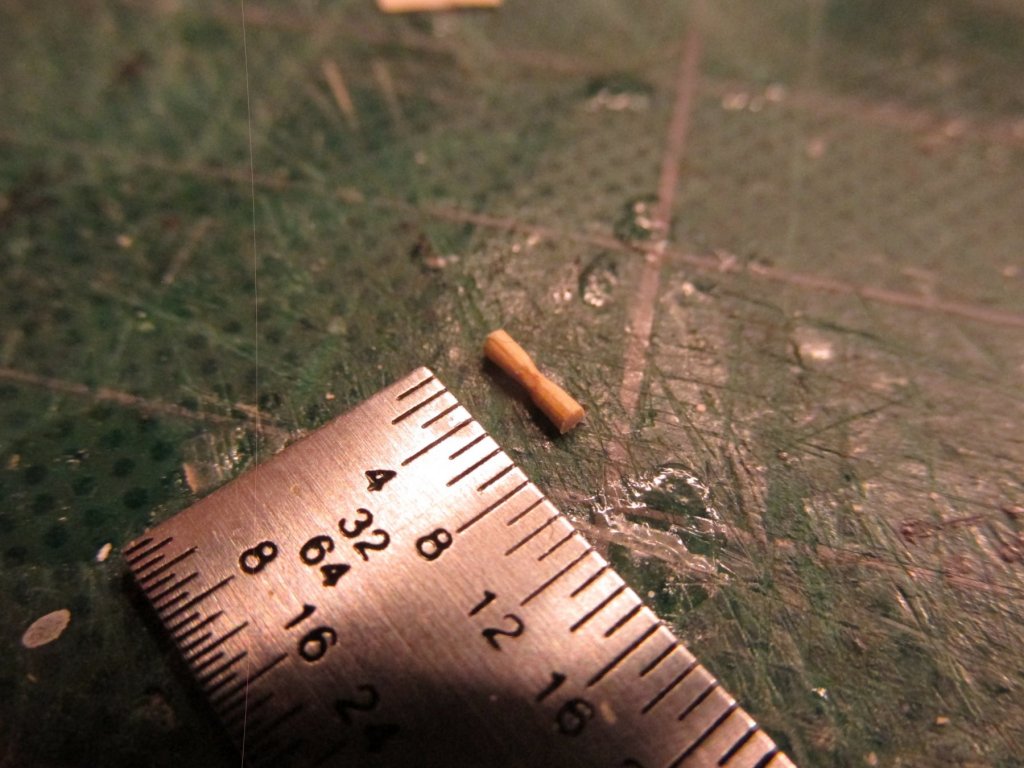
The bench is supported from below with pilasters. I made mine from bamboo skewers that are available at any grocery store. Using a Byrnes draw place, I made a 1/32” diameter “toothpick” and cut seven, 7/32” segments. Three for each side, and one for the apex. These were a bit long, but it gave me room to adjust the lengths to make them fit under the bench. The actual pilasters have a fancy curvy profile to them, so I filed the centers to create a subtle “hourglass” shape. The pilasters were then stained and glued to place.

-
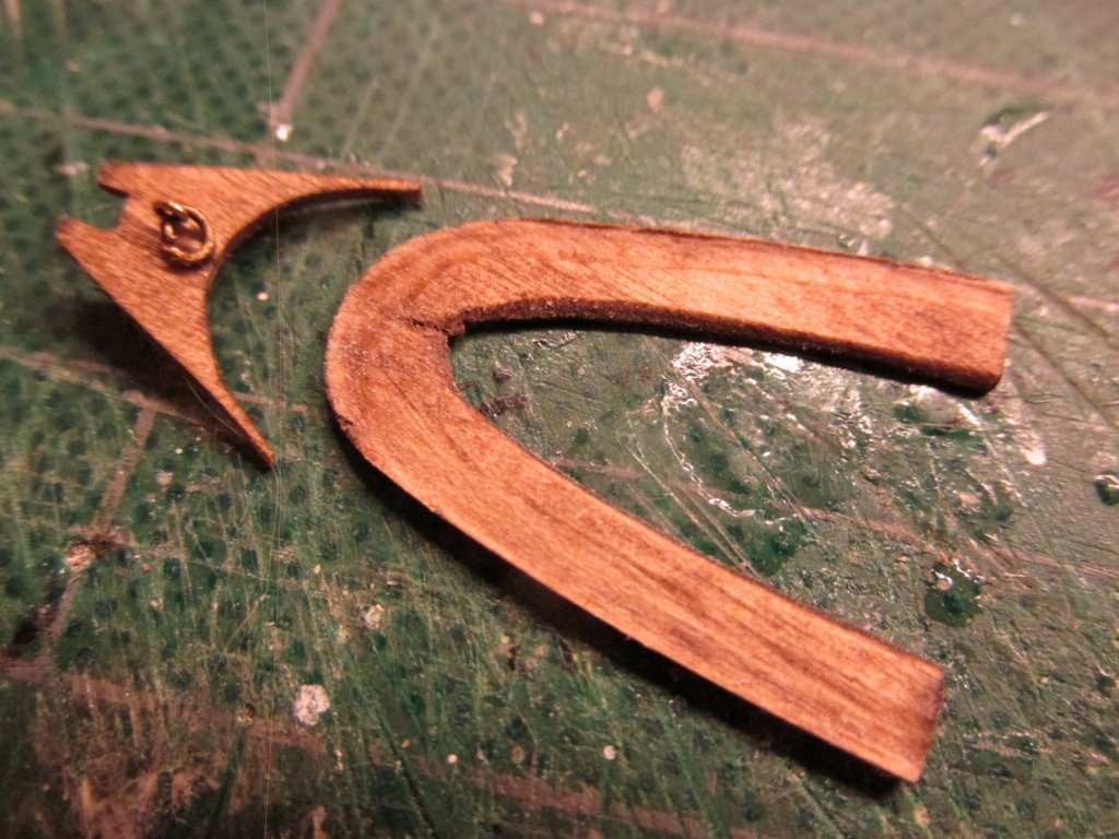
This a complicated area of the boat. The bench must fit in a corner with sloping sides coming to an apex at the stern post. Between the stern post and the bench there is supposed to be a covered area with a grating on top, a backrest behind the bench, all siting on a platform that has a ring assembly accessible when the grating is removed. I chose to make this platform separate from the bench although in hindsight, I could have made both the bench and platform from one piece of plywood. Here are the two components stained mahogany before installation and glued into place.

-
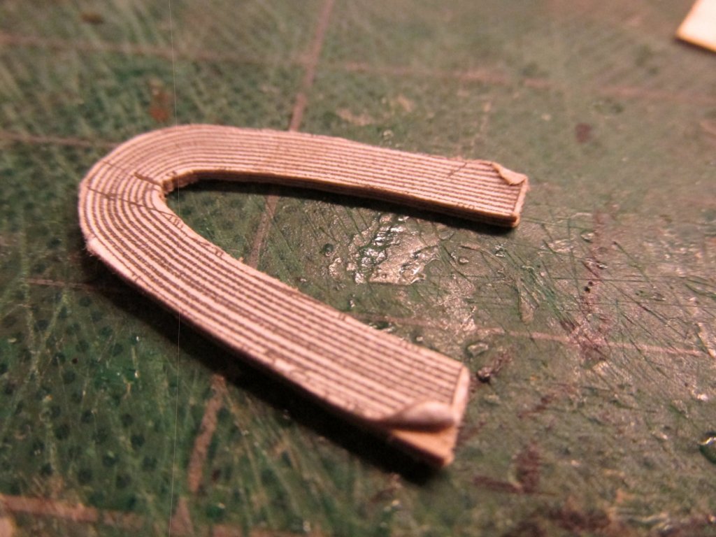
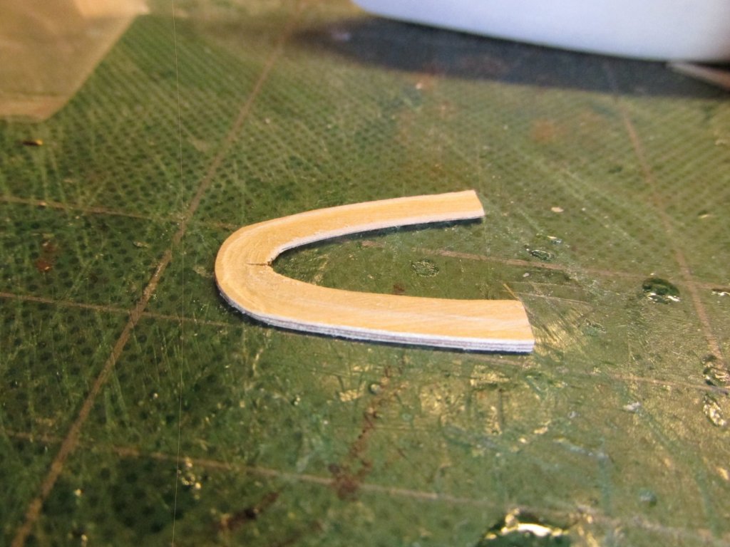
Gig Wrap Around Bench Seat The wrap around bench seat presented me with a conundrum. In the actual boat, the seat was made up from concentric slats separated by a space. One can see that in the template I made from the US Navy plans. However, the scale was just too small for me to simulate the slats and spaces. So, like others before me, I used to make the rough cut from 1/32” plywood. I did try to contour the seat profile so it would fit a scale tush as shown in the plans. I’m not certain whether I was successful at that or even if it was, would anyone even notice it. It was then dry fitted until if fit properly into position.
-
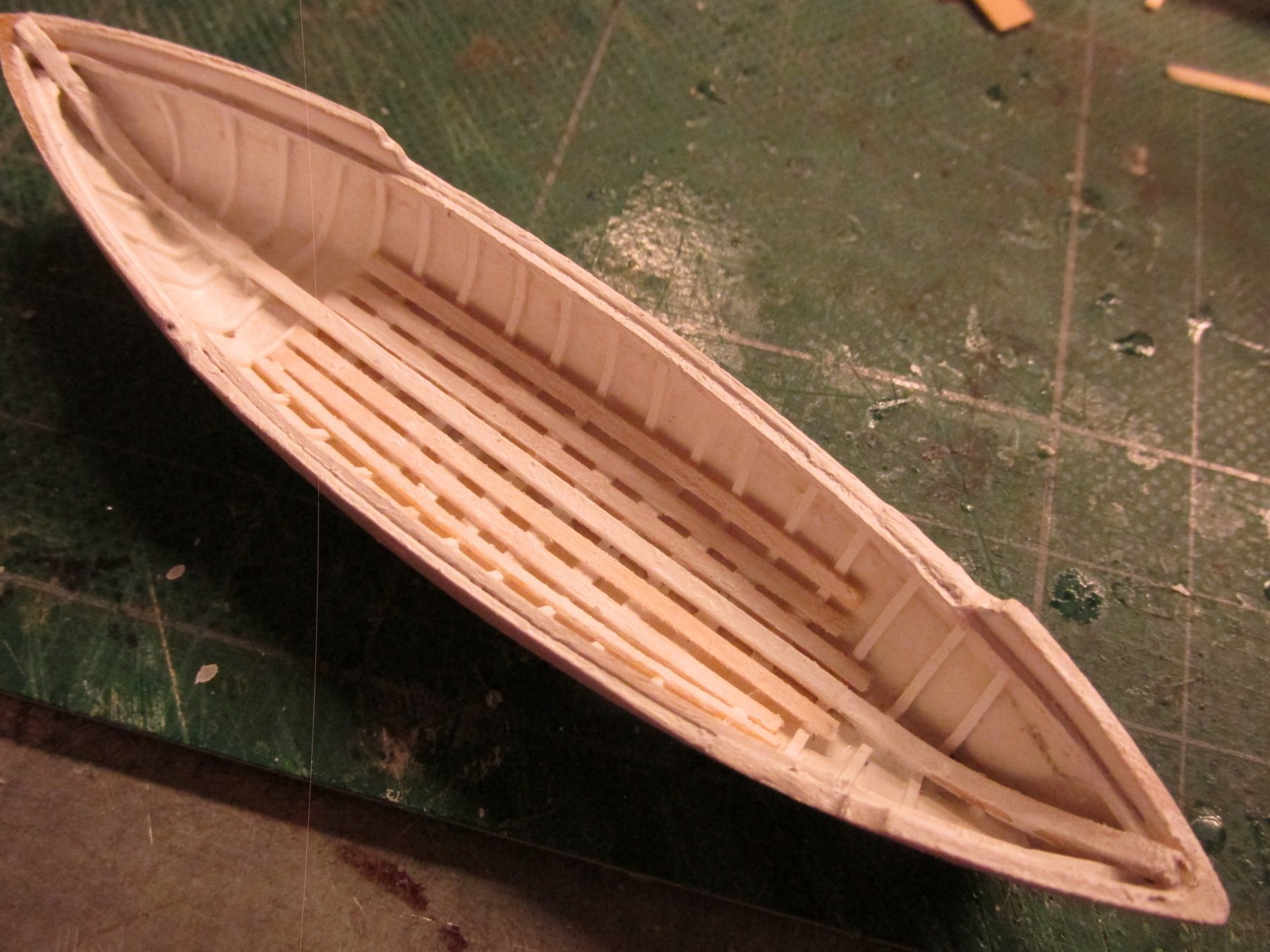
Remaining Gig Footrests The remaining 5 footrests were constructed and installed in a similar manner as the one over the grating. The footrest lengths did vary though.

-
Oh. very nice!! I sure hope you have plans to preserve your work, when she's finished, in a nice display. Jonathan
- 481 replies
-
- 2
-
-
- rattlesnake
- model shipways
- (and 1 more)
-
The footings were added and painted white. The sole was then installed.


-
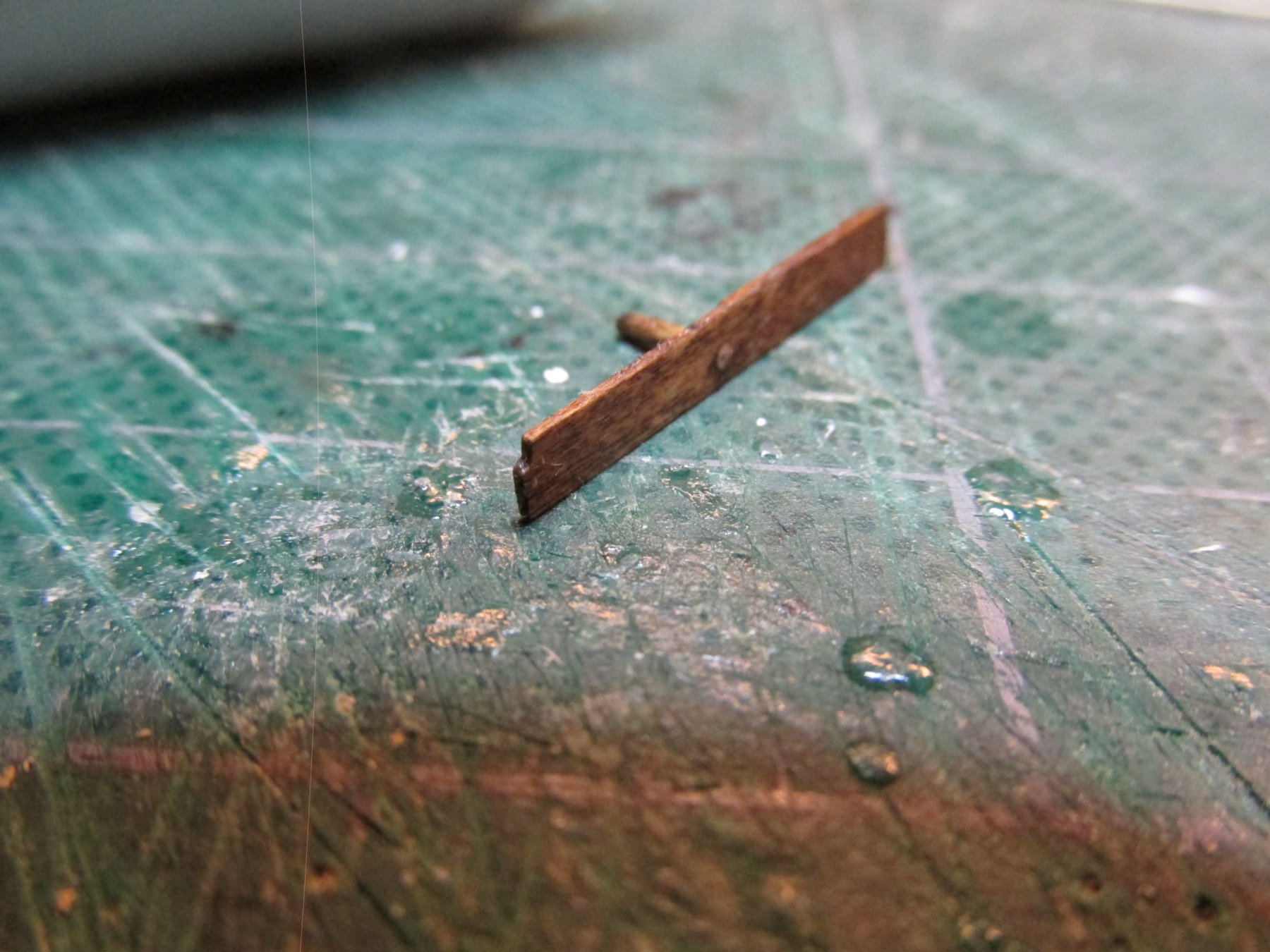
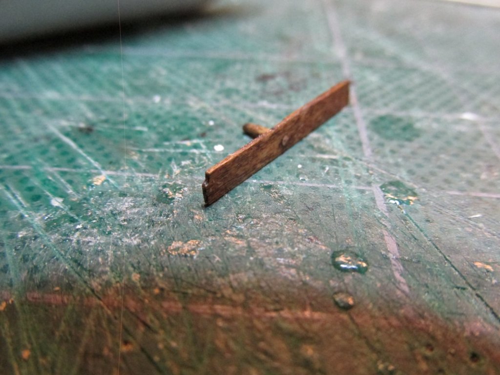
The footrest was made from 1/32” x 1/64” basswood, assembled with the supports, and stained mahogany. It was then set into place on the sole.