HOLIDAY DONATION DRIVE - SUPPORT MSW - DO YOUR PART TO KEEP THIS GREAT FORUM GOING! (Only 13 donations so far - C'mon guys!)
×


JSGerson
-
Posts
2,611 -
Joined
-
Last visited
Content Type
Profiles
Forums
Gallery
Events
Everything posted by JSGerson
-
 As I mentioned above (Aug 18, 2017 post), I used the same exact Armanti figures for my model. I got mine at Age of Sail. Jon
 -
Don't forget, you have to replace the bulwarks planks on the inner walls as well. I don't envy the work ahead for you. Good luck. Jon
- 481 replies
-
- 3
-

-
- rattlesnake
- model shipways
- (and 1 more)
-
You might want to use 5 minute epoxy glue on those joints. They will fill in any gaps, you have the luxury of a little time to set the pieces once the glue is in place, you can file/sand off any excess, and you can paint it. The main point though, due to the small gluing surfaces, I believe the epoxy will be a whole lot stronger. I used this method for the mast top stanchions on my Rattlesnake. (June 9. 2014 post). BTY, what kind of drill did you use to form the holes in the metal? All I have are wood drills which either bend or break if you breath on them too hard. Jon
- 742 replies
-
- 5
-
-
- constitution
- frigate
- (and 1 more)
-
I used those exact same figures for my Rattlesnake (post Feb 11, 2017). After I trimmed off the casting seams I dipped them in the same acid bath I used for blackening metal pieces to get rid of any oils left on the metal. To my surprised, the metal turned black as if I had blackened them. Just thought you might want to aware of that. Jon
-
Nice solution. When I use pins, I install the pin into item that needs to be glued to the deck. Then I position the item to its intended location and press the item so that the pin makes an impression on the deck. Then I drill a pin hole into the impression. Now the pin fits into the deck and the item is properly located. It doesn't matter that the pins don't necessarily line up with each other (because they are hidden), but that the resulting pieces are located in their respective positions. Jon
- 67 replies
-
- 2
-
-
- rattlesnake
- mamoli
- (and 1 more)
-
As always neat, clean, well photographed, and a pleasure to view and read. Jon
-
May I suggest you add metal pins to the underside of anything you're going to mount to the deck that will handle rigging line. The rigging line adds a lot of tension to bits and stanchions and may pull them off the deck. Trying to repair that kind of catastrophe is something I would want to wish on any model builder. Jon
- 742 replies
-
- 5
-
-
- constitution
- frigate
- (and 1 more)
-
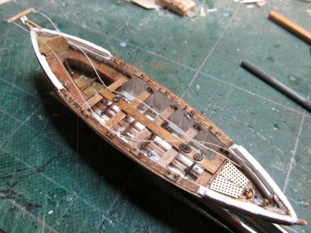
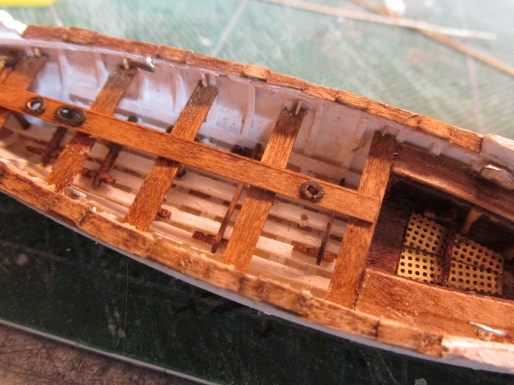
Gig Bumper The major element of the gig was the bumper. This was made from 1/32” square boxwood which was pre-bent by soaking in water and then using a hot iron wood bender. It makes gluing so much easier. Gig Completed The pintle and gudgeon were made of ordinary white paper wrapped the rudder and rudder post. According to the photographs on the actual ship they are white so I did not use a contrasting color to make them stand out. It’s part of my philosophy that less is more. Finally, I used ordinary beige sewing thread for the yoke tiller ropes.

-
The pins were created by inserting the long bamboo pin stock and cutting it in place to slightly larger than needed length. Once all the pins were in place I then trimmed the pins to their proper length and filed their ends to approximate the slightly conical pointed end.
-
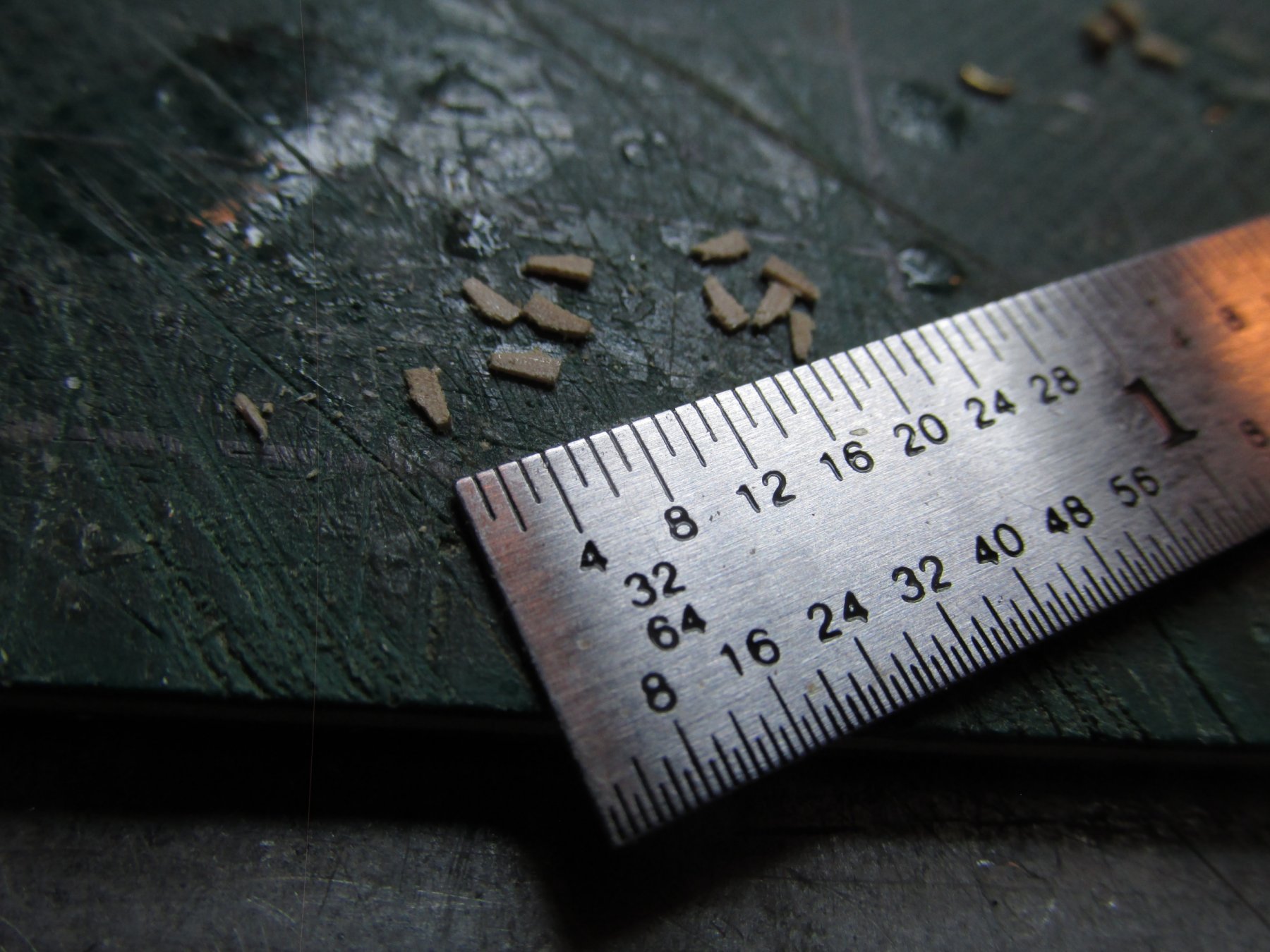
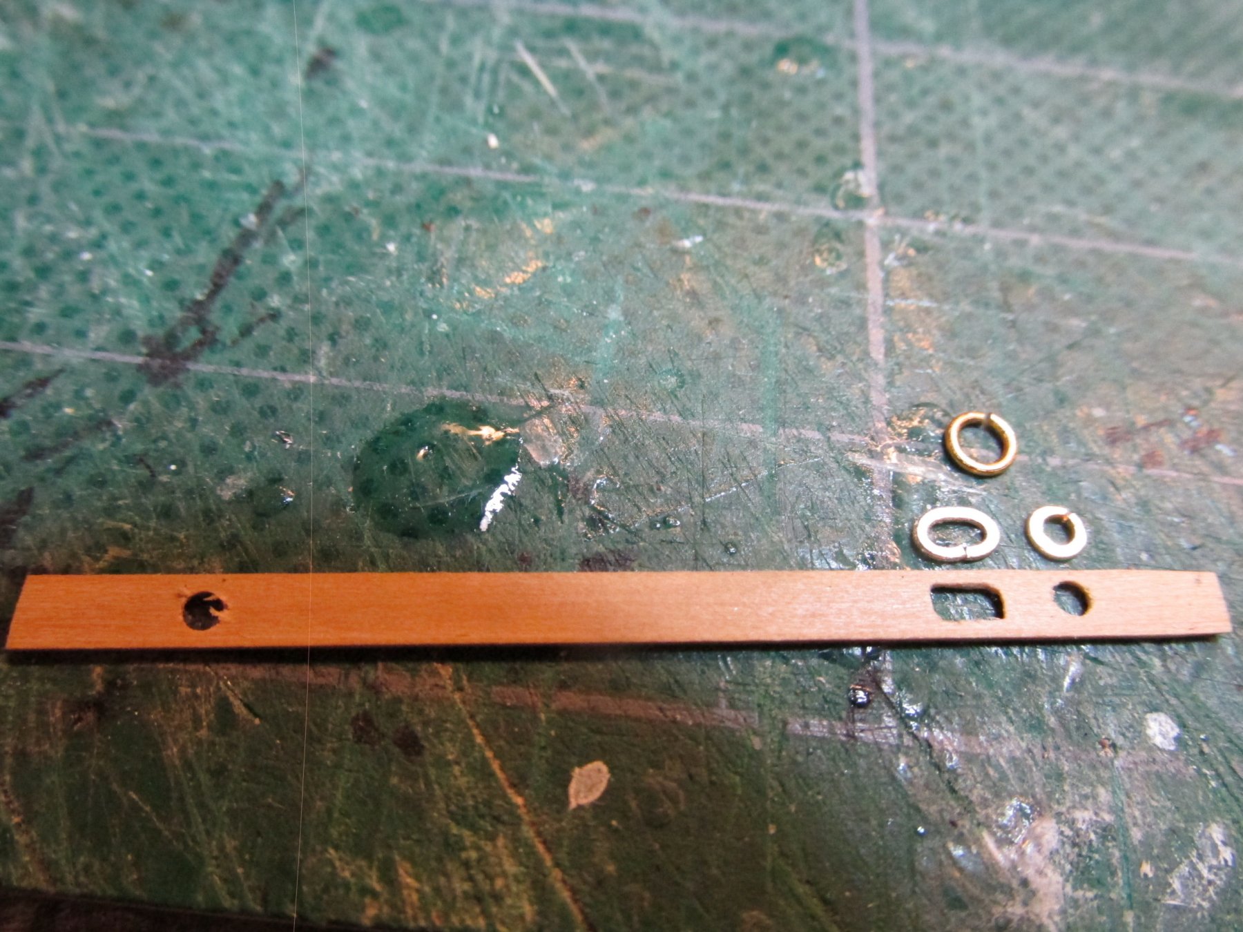
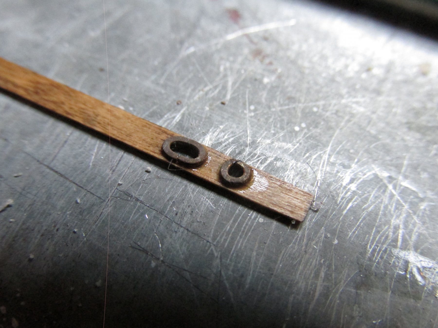
Gig Thole Pins The US Navy’s plans provide excruciating detail of the thole pins; way too much detail for this level of scale. The pins are not cylinder shaped but slightly conical; do not have a circular cross section, more oblong; come to a flattened rounded point at the top; and the pairs aren’t even the same shape. So like many of the other builders who decided to include thole pins, I chose to make mine circular cross section with a flattened pointed top. Using a Byrnes draw plate, I drew down bamboo skewers close to 7/128” in diameter. The thole plate was supposed to be 1/128” thick but I didn’t dare get any thinner than 1/64”. My idea was to make the plates, drill the two thole pin holes, add the pins and use CA glue. Once the CA dried solid, I would trim the pins and sand the bottom of the plate and again using CA glue into position. Drilling two holes in the plate for the pins was next to impossible because as soon as the drill bit started to turn, the wood would split. I then used Plan B. I stained the plate first hoping the stain would act a bit like glue in the grain of the wood. Then I glued the plate into position on the rail to provide additional structural strength. Then I drilled the hole for the pins. Even then, I had one plate split.
-
i was think more in terms of the material for the hammocks than the additional detail.
- 108 replies
-
- 2
-
-
- mamoli
- constitution
- (and 2 more)
-
You might want to take a look at Tlevine's build of the HMS Atalant (March 23, 2014 post) for the hammocks and see if that will help. Jon
- 108 replies
-
- 2
-
-
- mamoli
- constitution
- (and 2 more)
-
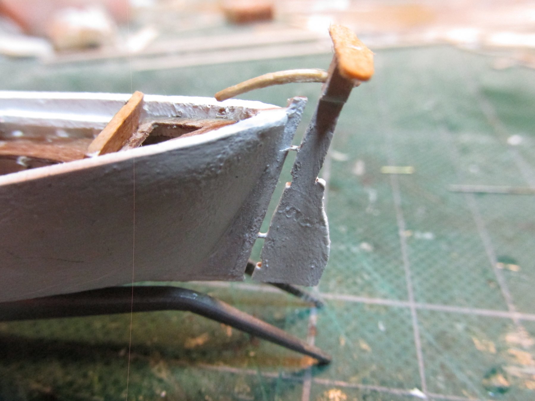
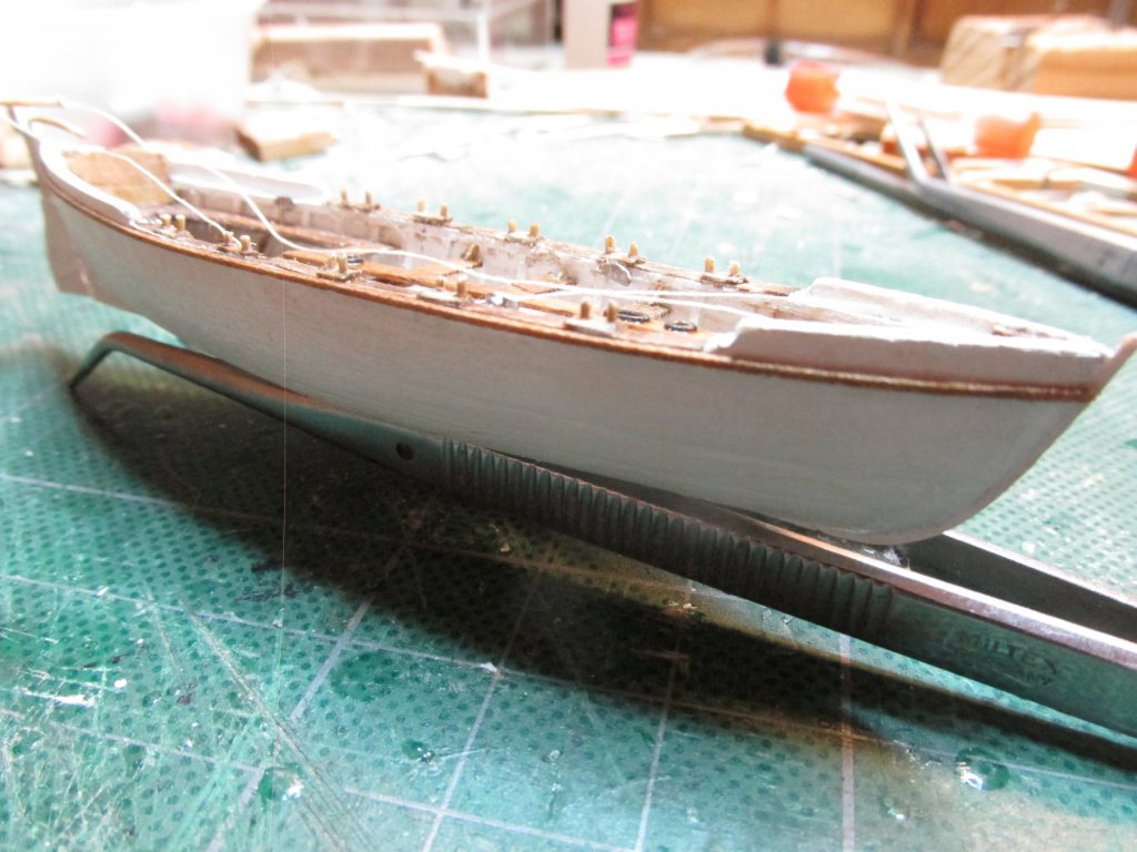
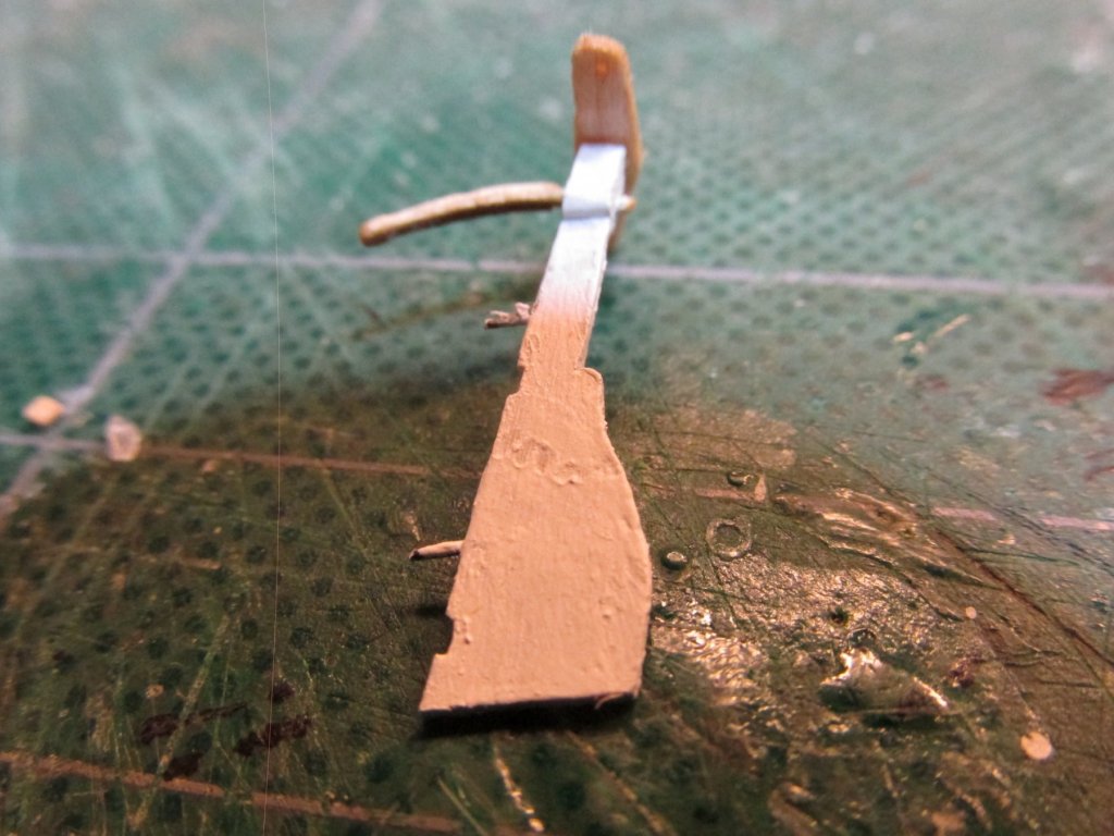
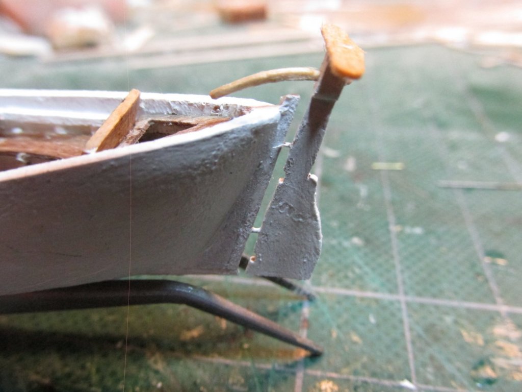
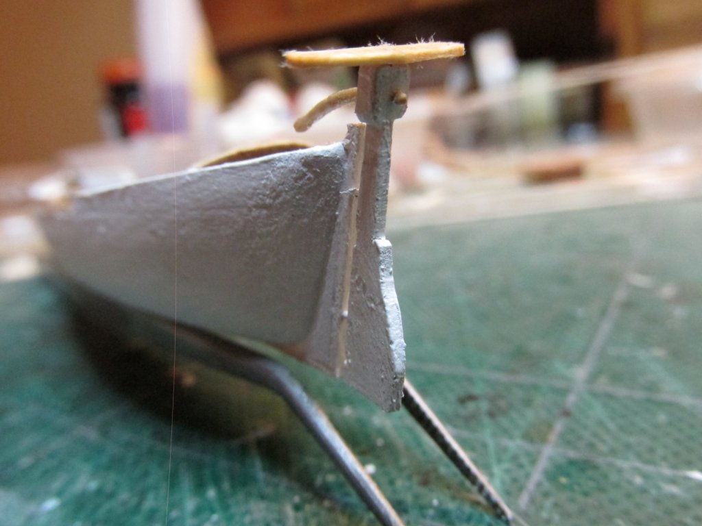
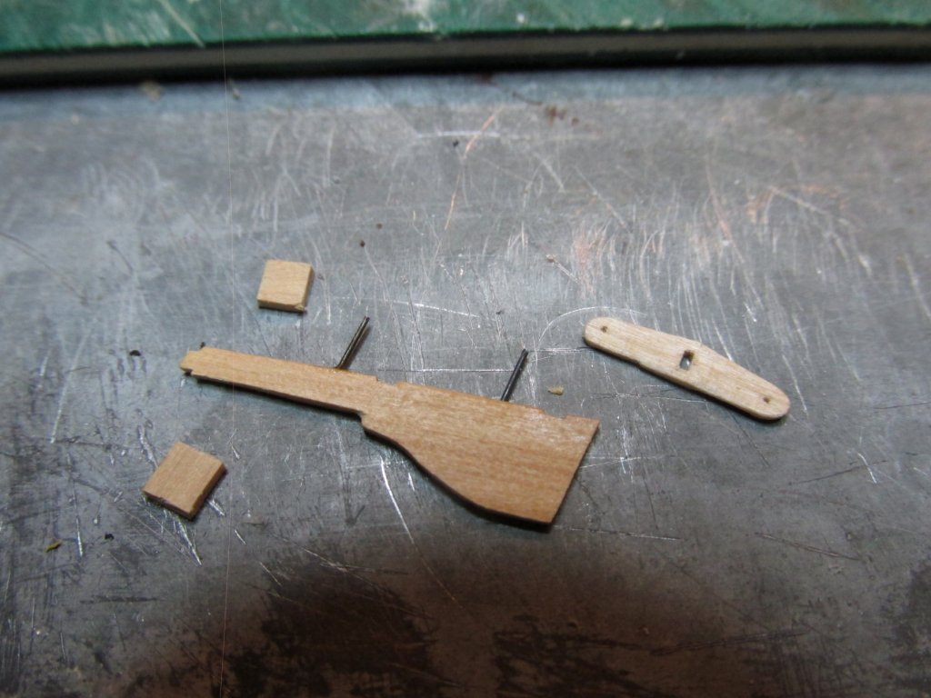
The rudder was painted white. It look almost all brown in the image but that was just the shadow of the camera lens. The yoke tiller and the standard yoke are unpainted oak on the actual boat so these were given a light stain. The standard tiller looks awfully short to my eyes, but it matches perfectly with the kit’s plans. These pictures show the dry fit. They will be permanently assembled as a last step.
-
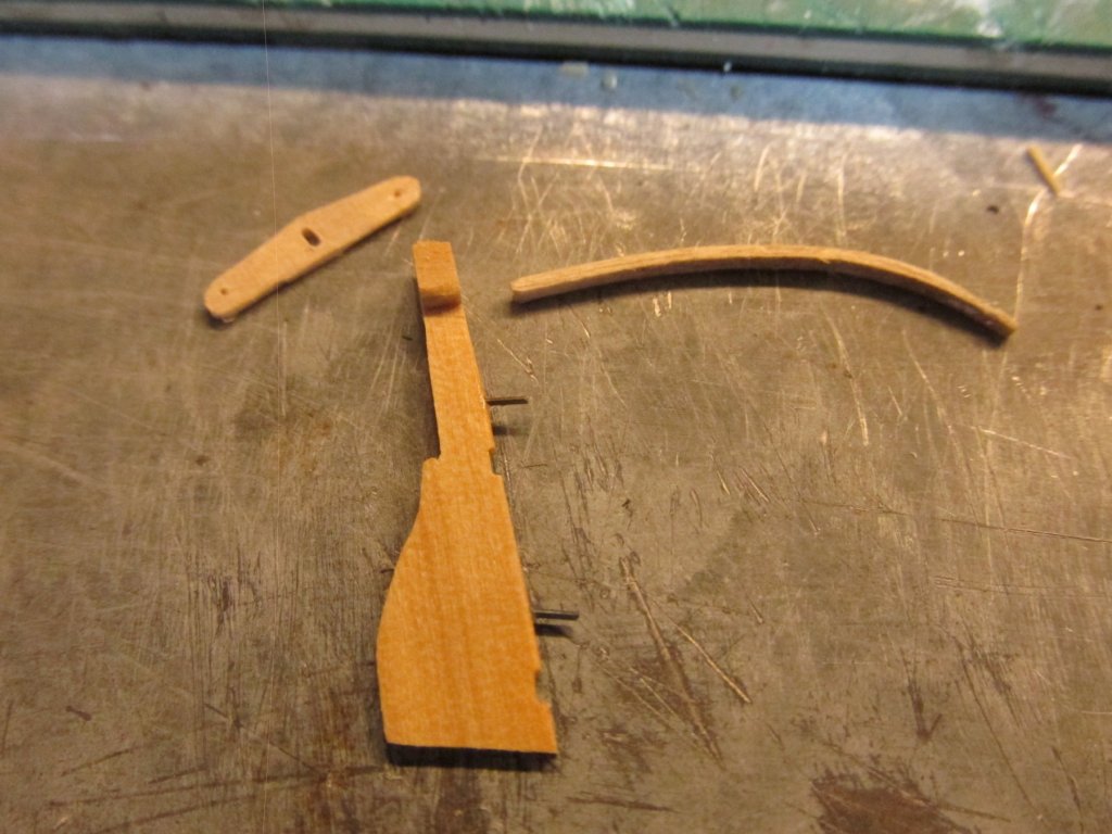
Gig Rudder Assembly Using the US Navy plans to make the templates for the rudder parts. I used 1/32” boxwood here because the rudder has some sharp curves and I wanted clean edges. Basswood can be a bit fuzzy. Both the kit plans and the US Navy plans show a yoke tiller. The US Navy plans show a hole for a standard tiller (but no plan of it) which I assumed was to give the occupants of the boat a choice of steering methods. The kit shows the tiller installed along with the yoke tiller. I would assume you would have one or the other, not both. But I’m not a sailor, I don’t know. I’ve looked at other builder’s models and of those that went to the trouble of making a yoke tiller, also had the standard tiller installed as well. So, unless someone can definitively state use one or the other, I’ll install both. The first picture below shows the parts of the rudder and the yoke tiller. The second image show the rudder partial assembled and a bent 1/32” stock to be used for the standard tiller. The rudder ended up being about 3/128” thick after sanding which is what the US Navy plans call for at scale. This required that I use very small diameter pins to secure the rudder to the stern. I used broken #80 drill bits. They are very thin, stiff, strong, and dark in color which will make them all but invisible. As I have mentioned before, I don’t throw away scraps. The broken bits are a case in point.
-
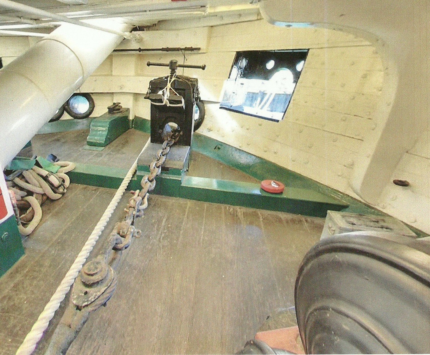
I'm not surprised you couldn't find an image. Usual when I look for one item I find another, total unrelated. I copy it and add it to my extensive library. Just for grins and giggles, I tried to find that image again with Google using keywords and similar images, no luck. My guess for its use is to hold the chain from playing out once the anchor is dropped, not to hold up. If you look closely, you can see that the screw does not press on the chain. It presses on the wood yoke which in this picture opened. Glad I could help Jon
- 742 replies
-
- 7
-
-
- constitution
- frigate
- (and 1 more)
-
It's probable too late, but I did have one image of the "vise."

- 742 replies
-
- 8
-
-
- constitution
- frigate
- (and 1 more)
-
Oooh! I like that. But as always, I have questions: drill bits #80 - 61. If I wanted to follow your example for making the stars, I would need metal cutting drill bits. If I were to order drill bills from Model Expo for example, I would assume the bits would be designed for wood. How are metal cutting drill bits designated? Other being tougher, are they designed differently? Where do you buy them? Thanks Jon
-
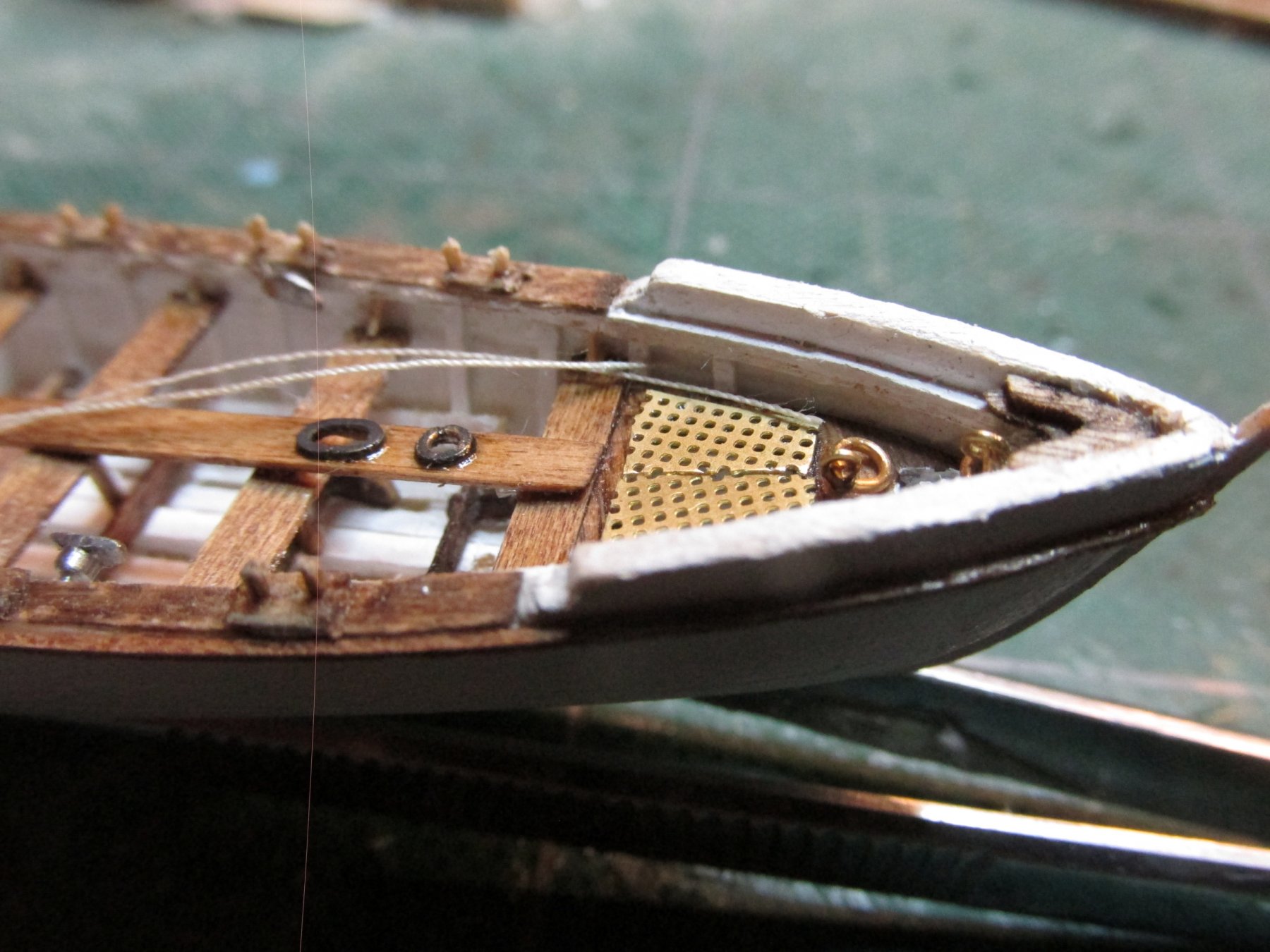
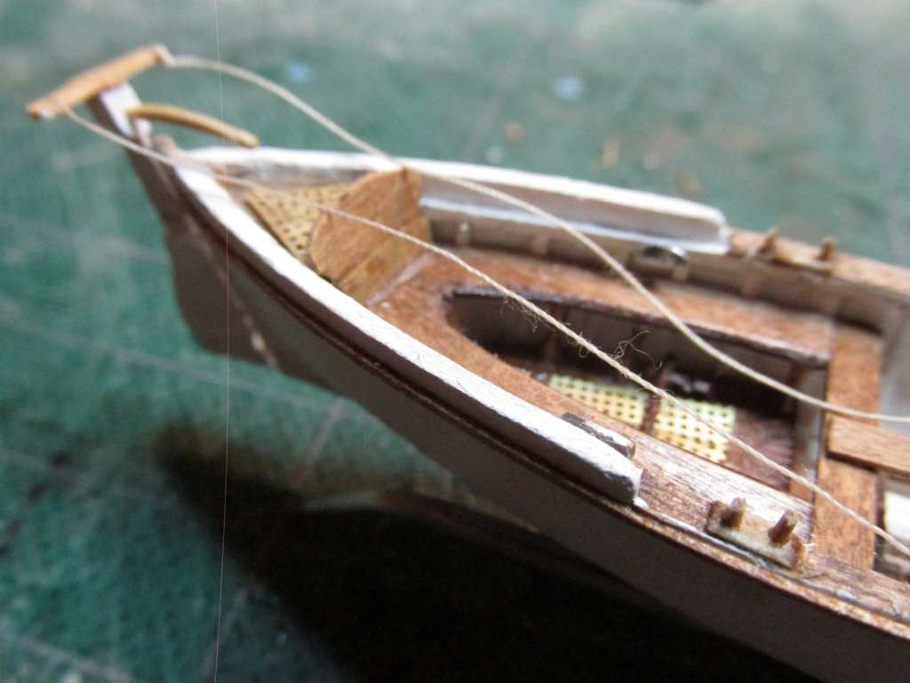
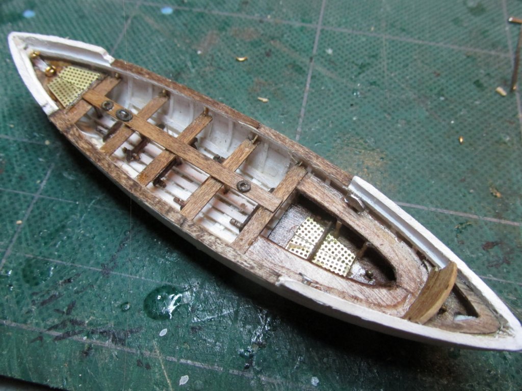
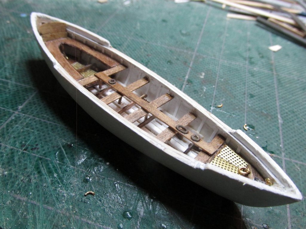
Gig Rail Cap On the full-scale US Navy drawing, the rail cap is ½”. At scale, that works out to be 0.0065” abou the thickness of s piece of copy paper. As it so happens, like many of you model builders, we don’t throw anything away. What is scrap to one person is perfection to another. While cutting a piece of stock to size with Byrnes saw, I sliced off a strip of paper thin wood. It was perfect for the rail cap. First the strip was stained. Then two pieces where used to cover the rail using PVC glue. Once set, the excess was trimmed off with an X-actor knife and file. Finally, 4 cleats were made as before for the pinnace, and installed. The was one small caveat, the stern grating has vanished into the land of lost socks. I had picked up the gig and forgetting that the grating was on the boat, turned it over and felt something hit my bare foot. At least I think it did. I did everything but rip the rug off the floor. No luck. So, for now, it’s gone and maybe it will make miraculous appearance before I need it again. Otherwise I’ll have to make it again.
-
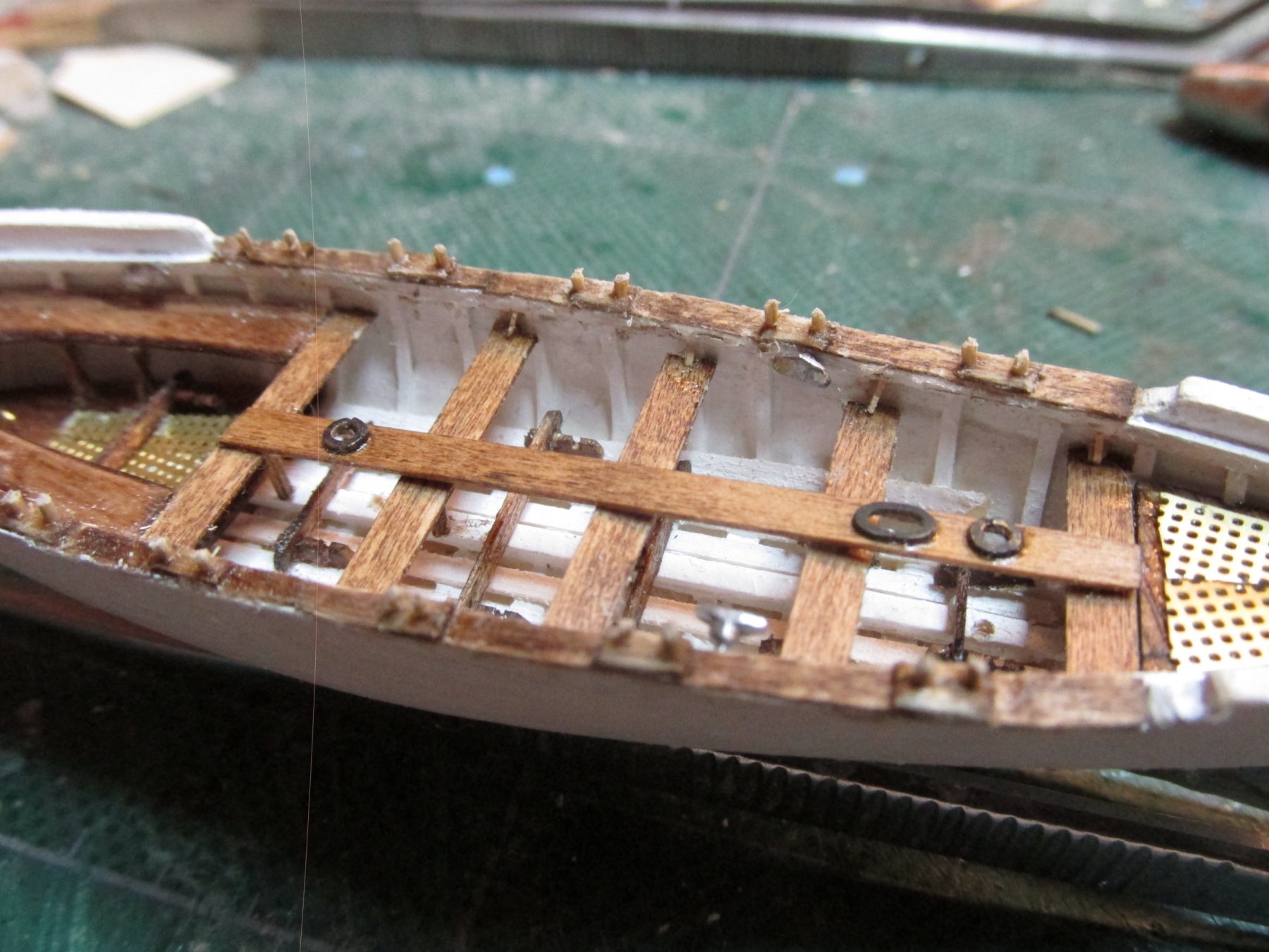
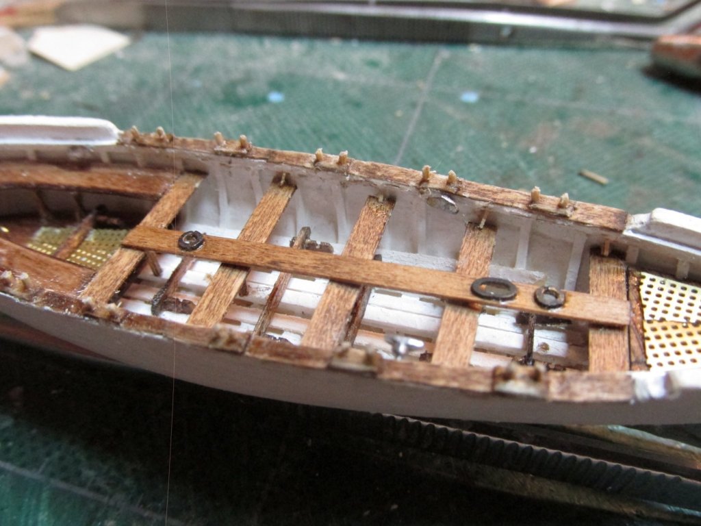
Gig Thwart Braces The thwart braces are almost not required for a boat of this scale, they are so small. But I like like to pull the viewer in so the closer they get, the more they discover. A case in point was my Rattlesnake’s tree nails. I deliberately did not use a high contrasting color so that they would be noticeable. Only when one looked real close did you realize they were there. The same is true of the braces. These thing are tiny as should on the scale plans: 5/32” x 1/64”. On my model, they are a bit smaller due to my lack of building skills to maintain that kind of tolerance. I had to trim them to make they fit.

-
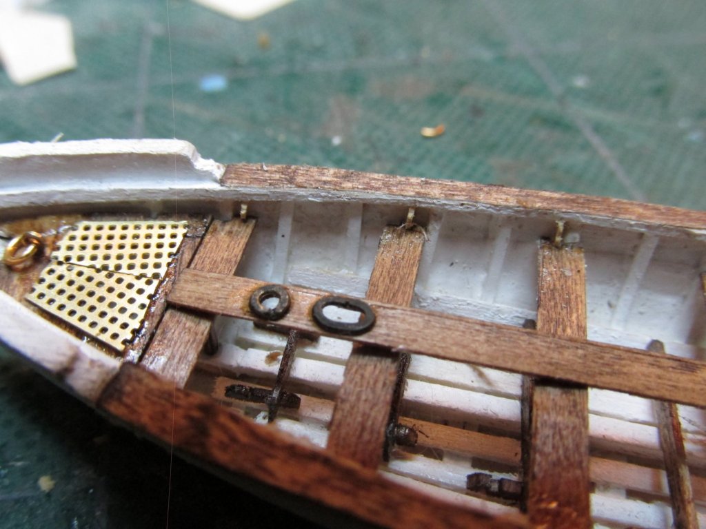
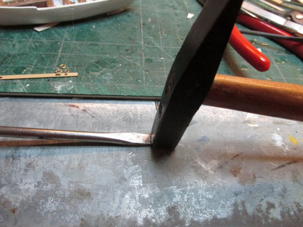
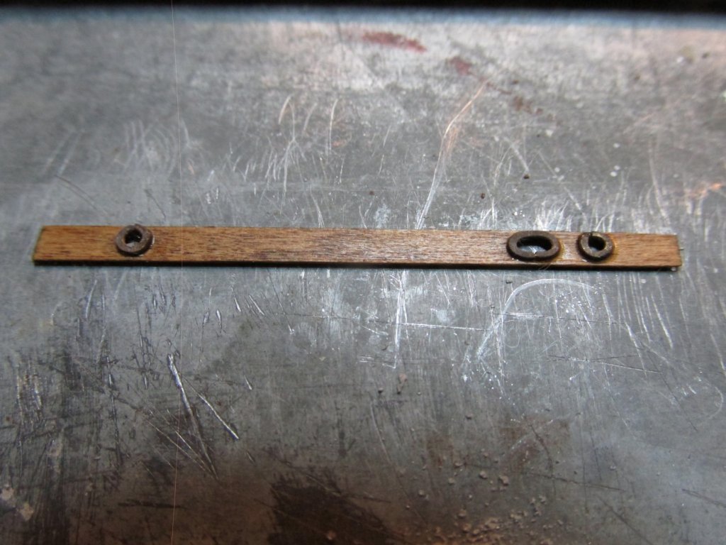
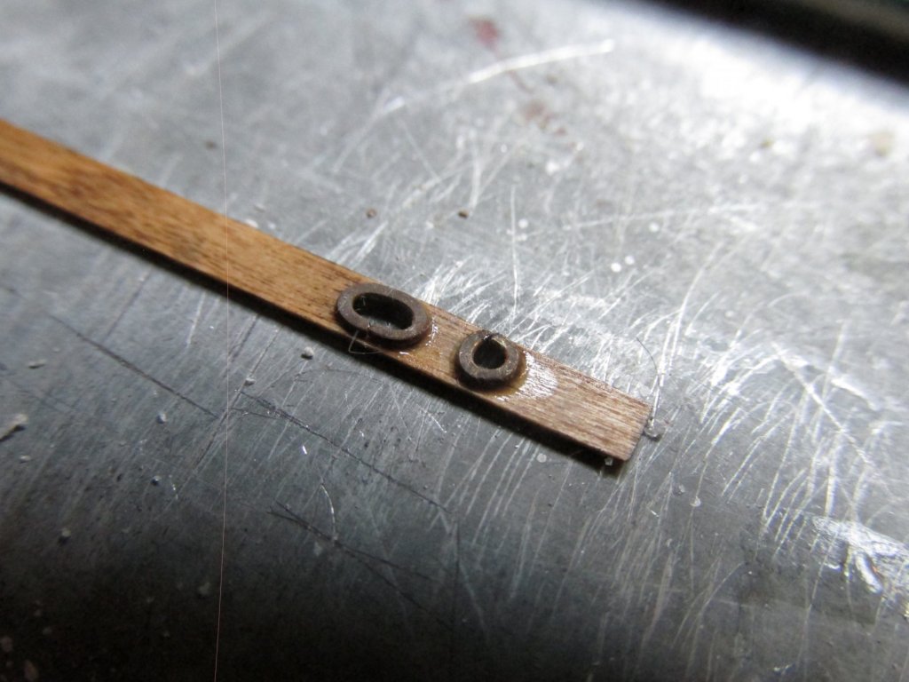
Gig Gangway Board The gig gangway board lies on top of the thwarts with holes for the masts. This was made from 1/8” x 1/64” boxwood. The mast rings were formed from 1/8” split rings cut to size and shaped. Then using the wide flat face of a screw driver lying on the ring, it was pounded a couple of times with a hammer to flatten the wire. The forms were then blackened and glued into position.

-
Yes, I know, I’ve been terribly slow in my posts, especially for such small models as these boats. But personal events have taken precedence. My roof was still not permanently fixed and couldn’t be until I had resolved my TV satellite problem. Dish came twice to my home trying to find a location for the new satellite dish which did not violate their safety rules for installation and which would provide a clear line-of-site to the satellites. They failed. Unfortunately, I had to cancel that account and got a cable company to install their system. That killed two to three days. My iPhone acted up and that took a couple of days to resolve. My car battery died, and then my jumper cables broke when I tried to hook up to another car. I lost a half day getting help, a new battery, and new jumper cables. My A/C stopped working again but this time it wasn’t a coolant leak but a faulty solenoid switch. I’m in hot, humid South Carolina and A/C comes first before anything. The unit is 13 years old so it may be time to get a new one…eventually. The roofer finally was here yesterday and permanently fixed the roof. So, as I type this, the cars works again, the iPhones works as it is supposed to once more, the trees are trimmed, the TV satellite dish has been removed from the roof and the other was abandoned in place on the chimney, and the new TV cable system has been installed. All is good with the world once again. Back to the build.
-
I found this somewhere, sometime in the past: Scale Conversion Formula By: Rob Johnson (robj@speechsys.com) Scales are ratios of measures in like units: 1/72 is 1 inch on the model = 72 inches on the full-sized original (or 1 centimeter, furlong, or parsec on model to 72 of same at full size). The desired scale is then the existing scale times some unknown percentage or fraction, i.e. the conversion factor (either enlargement or reduction): DesiredScale = ExistingScale * ConversionFactor Therefore, to find the conversion factor, we regroup and divide to get the universal scale conversion formula: ConversionFactor = DesiredScale / ExistingScale Example: to convert 1/72 to 1/48 ConversionFactor = 1/48 / 1/72 = 72 / 48 = 1.5 = 150% A 6-ft (72-inch) pilot figure is thus 1-in tall in 1/72 scale and 1.5-in tall in 1/48 scale. Advantages of the formula: You can always figure out the intermediate ratios correctly when using photocpier enlargement. In the above example, most copiers would not do the full 150% in one pass. Most copiers max out at 121% or 141%. I have seen almost every other possible figure too. So having a chart of common scale conversions is not likely to be all that useful in many cases. Using the formula, you just figure out what the scale will be after the 121% enlagement: IntermediateScale = ( ExistingScale * .121) + ExistingScale. Then you use IntermediateScale as the ExistingScale in the formula.
-
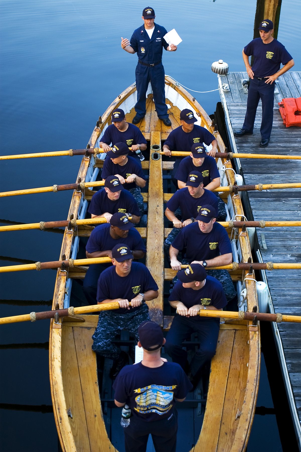
In the picture below of one of the whaleboat from the Conny, you can see some of ropework treatment on the oars. As for lashing, I think you could do anything and I don't think anyone could prove you wrong.

-
You may want to look at this for inspiration, tips, and techniques: BUILDING A SHIP’S STOVE, Allan Yedlinsky
- 742 replies
-
- 3
-
-
- constitution
- frigate
- (and 1 more)